DNS Study on Three Vortex Identification Methods · 1 American Institute of Aeronautics and...
11
http://www.uta.edu/math/preprint/ Technical Report 2016-07 DNS Study on Three Vortex Identification Methods Yinlin Dong Yong Yang Chaoqun Liu Γ
Transcript of DNS Study on Three Vortex Identification Methods · 1 American Institute of Aeronautics and...
http://www.uta.edu/math/preprint/
Technical Report 2016-07
DNS Study on Three Vortex Identification Methods
Yinlin Dong Yong Yang
Chaoqun Liu
Γ
1 American Institute of Aeronautics and Astronautics
DNS Study on Three Vortex Identification Methods
Yinlin Dong1, Yong Yang2 and Chaoqun Liu3
University of Texas at Arlington, Arlington, Texas, USA
Vorticity, vorticity line and vorticity tube have rigorous definitions, but vortex has not been mathematically defined yet. It is realized that vortex is not vorticity tube and must be given a more rigorous definition, at least by some accurate identification methods. The current paper comperes two popular vortex identification methods, Q-criterion and Lambda 2 with the new Omega vortex identification method by visualization of several examples studied by direct numerical simulation and large eddy simulation for flows with different speeds. The comparisons show the Omega method is more close to give a mathematical definition of vortex and better visualization for vortex structures. Additional advantages include clear physical meaning and no need to adjust threshold, which make Omega the most effective and efficient tool in vortex identification.
1. Introduction
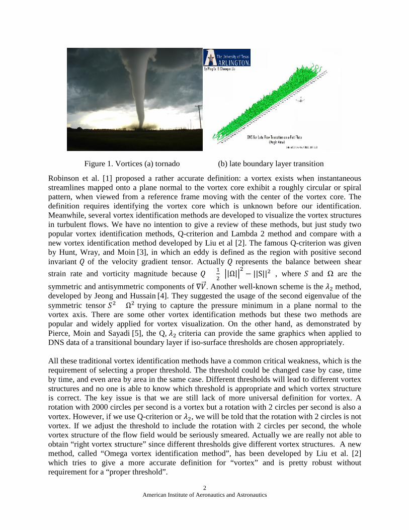
“Vortex” is a common phenomenon in nature from tornado to turbulence. For example, turbulence is a vortex buildup process (Figure 1). Investigators have realized that turbulence is not a purely stochastic process, but a process with coherent vortical structures which play a decisive role in fluid dynamics and energy transport. Therefore, accurate visualization of vortices from huge amount of data obtained by experiments and numerical simulations becomes a key issue to solve the turbulence which is a century-long scientific problem. Vorticity, vorticity line and vorticity tube have rigorous definitions and we really do not have much room to discuss, but vortex definition is still an open question:
1) Vorticity: Vorticity is rigorously defined as the curl of a velocity field, which is a vector.
2) Vorticity line: a curve which is everywhere tangent to the local vorticity vector.
3) Vorticity tube: a tube-like surface formed by all vorticity lines passing through a closed curve, which could be considered as a bundle of vorticity lines without any vorticity line leakage. We cannot call something “tube” if it is leaking.
4) Vortex: a rigorous mathematical definition of vortex is still lack. Vortex definition and identification have been a research subject for long time. However there are several popular vortex identification methods based on the rotation nature of vortex. 1 PhD student, Department of Mathematics, University of Texas at Arlington 2 PhD student, Department of Mathematics, University of Texas at Arlington 3 Distinguished Professor, Department of Mathematics, University of Texas at Arlington
2 American Institute of Aeronautics and Astronautics
Figure 1. Vortices (a) tornado (b) late boundary layer transition
Robinson et al. [1] proposed a rather accurate definition: a vortex exists when instantaneous streamlines mapped onto a plane normal to the vortex core exhibit a roughly circular or spiral pattern, when viewed from a reference frame moving with the center of the vortex core. The definition requires identifying the vortex core which is unknown before our identification. Meanwhile, several vortex identification methods are developed to visualize the vortex structures in turbulent flows. We have no intention to give a review of these methods, but just study two popular vortex identification methods, Q-criterion and Lambda 2 method and compare with a new vortex identification method developed by Liu et al [2]. The famous Q-criterion was given by Hunt, Wray, and Moin [3], in which an eddy is defined as the region with positive second invariant 𝑄𝑄 of the velocity gradient tensor. Actually 𝑄𝑄 represents the balance between shear strain rate and vorticity magnitude because 𝑄𝑄 = 1
2(�|Ω|�
2− ||S||2) , where 𝑆𝑆 and Ω are the
symmetric and antisymmetric components of ∇𝑉𝑉�⃗ . Another well-known scheme is the 𝜆𝜆2 method, developed by Jeong and Hussain [4]. They suggested the usage of the second eigenvalue of the symmetric tensor 𝑆𝑆2 + Ω2 trying to capture the pressure minimum in a plane normal to the vortex axis. There are some other vortex identification methods but these two methods are popular and widely applied for vortex visualization. On the other hand, as demonstrated by Pierce, Moin and Sayadi [5], the Q, 𝜆𝜆2 criteria can provide the same graphics when applied to DNS data of a transitional boundary layer if iso-surface thresholds are chosen appropriately. All these traditional vortex identification methods have a common critical weakness, which is the requirement of selecting a proper threshold. The threshold could be changed case by case, time by time, and even area by area in the same case. Different thresholds will lead to different vortex structures and no one is able to know which threshold is appropriate and which vortex structure is correct. The key issue is that we are still lack of more universal definition for vortex. A rotation with 2000 circles per second is a vortex but a rotation with 2 circles per second is also a vortex. However, if we use Q-criterion or 𝜆𝜆2, we will be told that the rotation with 2 circles is not vortex. If we adjust the threshold to include the rotation with 2 circles per second, the whole vortex structure of the flow field would be seriously smeared. Actually we are really not able to obtain “right vortex structure” since different thresholds give different vortex structures. A new method, called “Omega vortex identification method”, has been developed by Liu et al. [2] which tries to give a more accurate definition for “vortex” and is pretty robust without requirement for a “proper threshold”.
3 American Institute of Aeronautics and Astronautics
2. Omega vortex identification method
The authors proposed a further decomposition of the vorticity to vortical part and non-vortical part after reviewed Helmoholtz velocity decomposition and some counterexamples like Blasius solution which has large vorticity but has no vortex. A so-called “Ω visualization method” is introduced to define and identify vortex. Ω is a ratio of vorticity squared over the sum of vorticity squared and deformation squared. According to the ratio, vortex is defined when vorticity overtakes deformation or Ω > 0.5. The iso-surface of Ω = 0.52 is utilized to represent the vortex surface and further the vortex structure of the flow field. This is an unprecedented effort to give vortex a mathematical definition. Being different from the traditional vortex identification methods, the Ω method is quite universal and has no need to set up a threshold case by case. In addition, the Ω method has other advantages which include being easy to perform, having clear physical meaning, and high capability to capture both strong and weak vortices. In general, people think vortex is “vorticity tube”, but the Ω method indicates that vortex is a region where vorticity overtakes deformation and vortex is not vorticity tube. Traditional vortex identification can cause many misunderstandings. For example, people believe turbulence is caused by “vortex breakdown”, but it is now understood that this is caused by wrong selection of vortex threshold.
Ω is defined as the following:
Ω =𝑇𝑇𝑇𝑇𝑇𝑇𝑇𝑇𝑇𝑇(𝐵𝐵𝑇𝑇𝐵𝐵)
𝑇𝑇𝑇𝑇𝑇𝑇𝑇𝑇𝑇𝑇(𝐴𝐴𝑇𝑇𝐴𝐴) + 𝑇𝑇𝑇𝑇𝑇𝑇𝑇𝑇𝑇𝑇(𝐵𝐵𝑇𝑇𝐵𝐵) + 𝜀𝜀 (1)
where 𝐴𝐴 is the symmetric part of velocity gradient tensor ∇𝑉𝑉�⃗ , 𝐵𝐵 is the anti-symmetric part and ε is a small positive number to avoid division by zero, i.e.
𝐴𝐴 =12�∇𝑉𝑉�⃗ + ∇𝑉𝑉�⃗ 𝑇𝑇� (2)
𝐵𝐵 =12�∇𝑉𝑉�⃗ − ∇𝑉𝑉�⃗ 𝑇𝑇� (3)
The vorticity magnitude ‖𝜔𝜔��⃗ ‖ can be further decomposed as a vortical part and a non-vortical part by Ω since Ω is a ratio of vortical part over the total vorticity, as follows
ωvor = Ω‖ω��⃗ ‖ (4)
ωnonvor = (1 − Ω)‖ω��⃗ ‖ (5)
where 𝜔𝜔𝑣𝑣𝑣𝑣𝑣𝑣 and 𝜔𝜔𝑛𝑛𝑣𝑣𝑛𝑛𝑣𝑣𝑣𝑣𝑣𝑣 present vortical part and non-vortical part respectively.
2.1 Comparison for late boundary transition
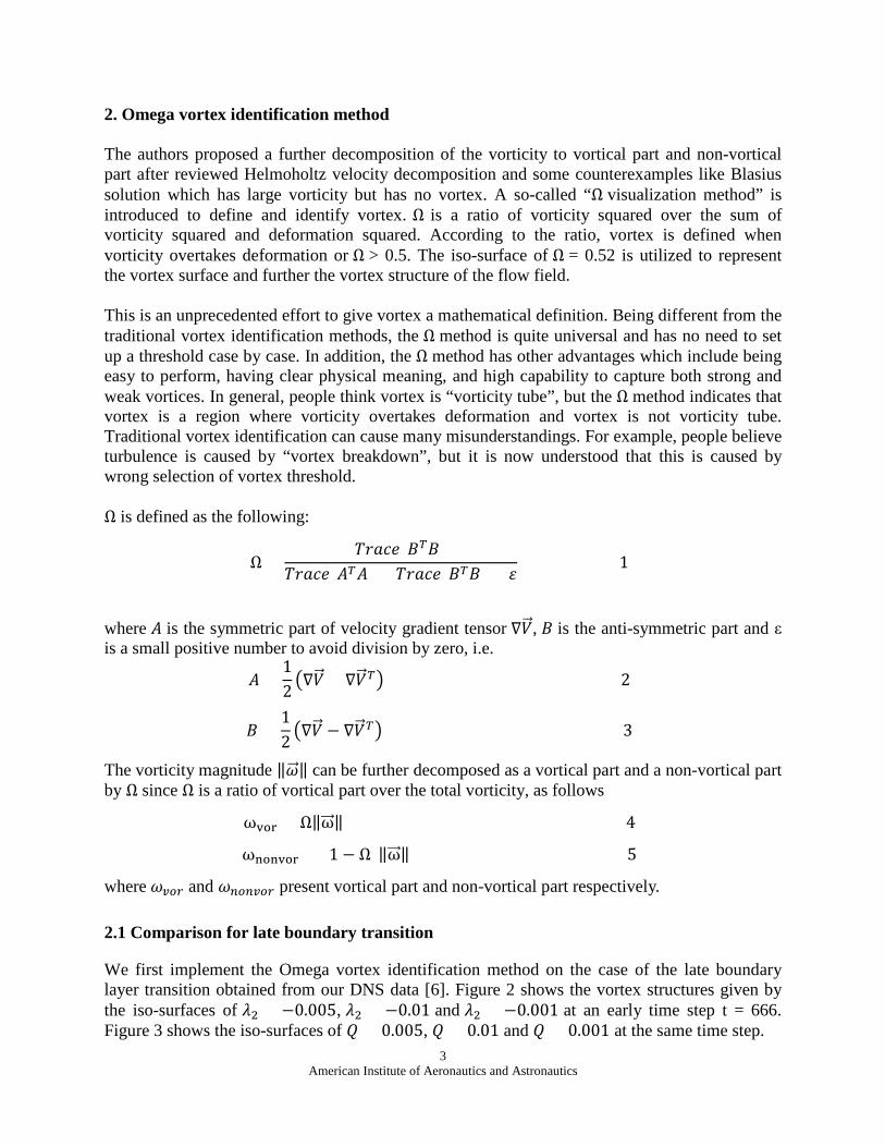
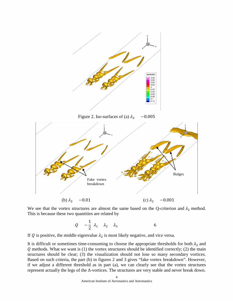
We first implement the Omega vortex identification method on the case of the late boundary layer transition obtained from our DNS data [6]. Figure 2 shows the vortex structures given by the iso-surfaces of 𝜆𝜆2 = −0.005, 𝜆𝜆2 = −0.01 and 𝜆𝜆2 = −0.001 at an early time step t = 666. Figure 3 shows the iso-surfaces of 𝑄𝑄 = 0.005, 𝑄𝑄 = 0.01 and 𝑄𝑄 = 0.001 at the same time step.
4 American Institute of Aeronautics and Astronautics
Figure 2. Iso-surfaces of (a) 𝜆𝜆2 = −0.005
(b) 𝜆𝜆2 = −0.01 (c) 𝜆𝜆2 = −0.001
We see that the vortex structures are almost the same based on the Q-criterion and 𝜆𝜆2 method. This is because these two quantities are related by
𝑄𝑄 = −12
(𝜆𝜆1 + 𝜆𝜆2 + 𝜆𝜆3) (6)
If 𝑄𝑄 is positive, the middle eigenvalue 𝜆𝜆2 is most likely negative, and vice versa.
It is difficult or sometimes time-consuming to choose the appropriate thresholds for both 𝜆𝜆2 and 𝑄𝑄 methods. What we want is (1) the vortex structures should be identified correctly; (2) the main structures should be clear; (3) the visualization should not lose so many secondary vortices. Based on such criteria, the part (b) in figures 2 and 3 gives “fake vortex breakdown”. However, if we adjust a different threshold as in part (a), we can clearly see that the vortex structures represent actually the legs of the Λ-vortices. The structures are very stable and never break down.
Fake vortex breakdown
Bulges
5 American Institute of Aeronautics and Astronautics
Figure 3. Iso-surfaces of (a) 𝑄𝑄 = 0.005
(b) 𝑄𝑄 = 0.01 (c) 𝑄𝑄 = 0.001
The part (c) in figures 2 and 3 seems to capture the vortex structures well, but the main structures are not as clear as those shown in part (a). Furthermore, there are some “bulges” above the Λ-vortex which might be thought as part of the Λ-vortex since another vortex layer seems to be on the top of the Λ-vortex in part (c), but these structures are not identified in part (a). Hence, the part (a) gives the most accurate visualization of the vortex structures in the late boundary layer transition. The larger magnitude of 𝜆𝜆2 and 𝑄𝑄 may cause fake vortex breakdown, while the smaller magnitude of 𝜆𝜆2 and 𝑄𝑄 may smear the vortex structures, making the vortices indistinguishable from each other. Here some questions arise. How do we know which thresholds of 𝜆𝜆2 and 𝑄𝑄 will capture the accurate vortex structures? What are the physical meanings of the different 𝜆𝜆2 and 𝑄𝑄 values?
Fake vortex breakdown
Bulges
6 American Institute of Aeronautics and Astronautics
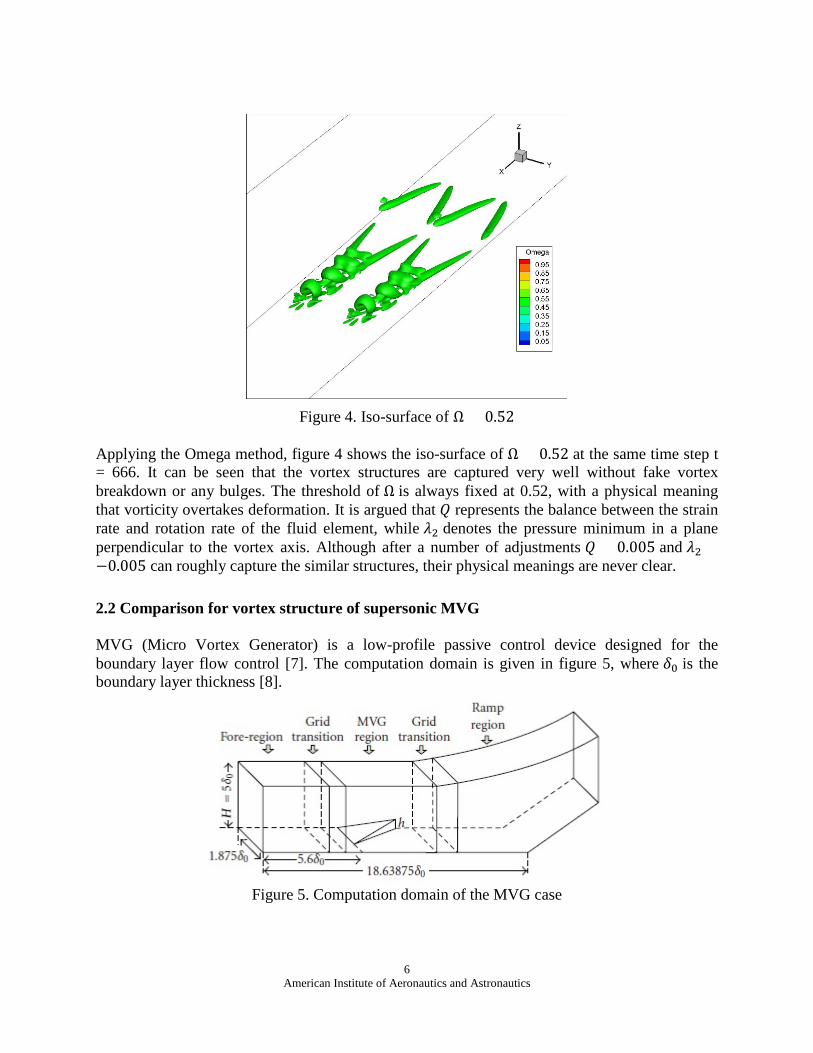
Figure 4. Iso-surface of Ω = 0.52
Applying the Omega method, figure 4 shows the iso-surface of Ω = 0.52 at the same time step t = 666. It can be seen that the vortex structures are captured very well without fake vortex breakdown or any bulges. The threshold of Ω is always fixed at 0.52, with a physical meaning that vorticity overtakes deformation. It is argued that 𝑄𝑄 represents the balance between the strain rate and rotation rate of the fluid element, while 𝜆𝜆2 denotes the pressure minimum in a plane perpendicular to the vortex axis. Although after a number of adjustments 𝑄𝑄 = 0.005 and 𝜆𝜆2 =−0.005 can roughly capture the similar structures, their physical meanings are never clear.
2.2 Comparison for vortex structure of supersonic MVG
MVG (Micro Vortex Generator) is a low-profile passive control device designed for the boundary layer flow control [7]. The computation domain is given in figure 5, where 𝛿𝛿0 is the boundary layer thickness [8].
Figure 5. Computation domain of the MVG case
7 American Institute of Aeronautics and Astronautics
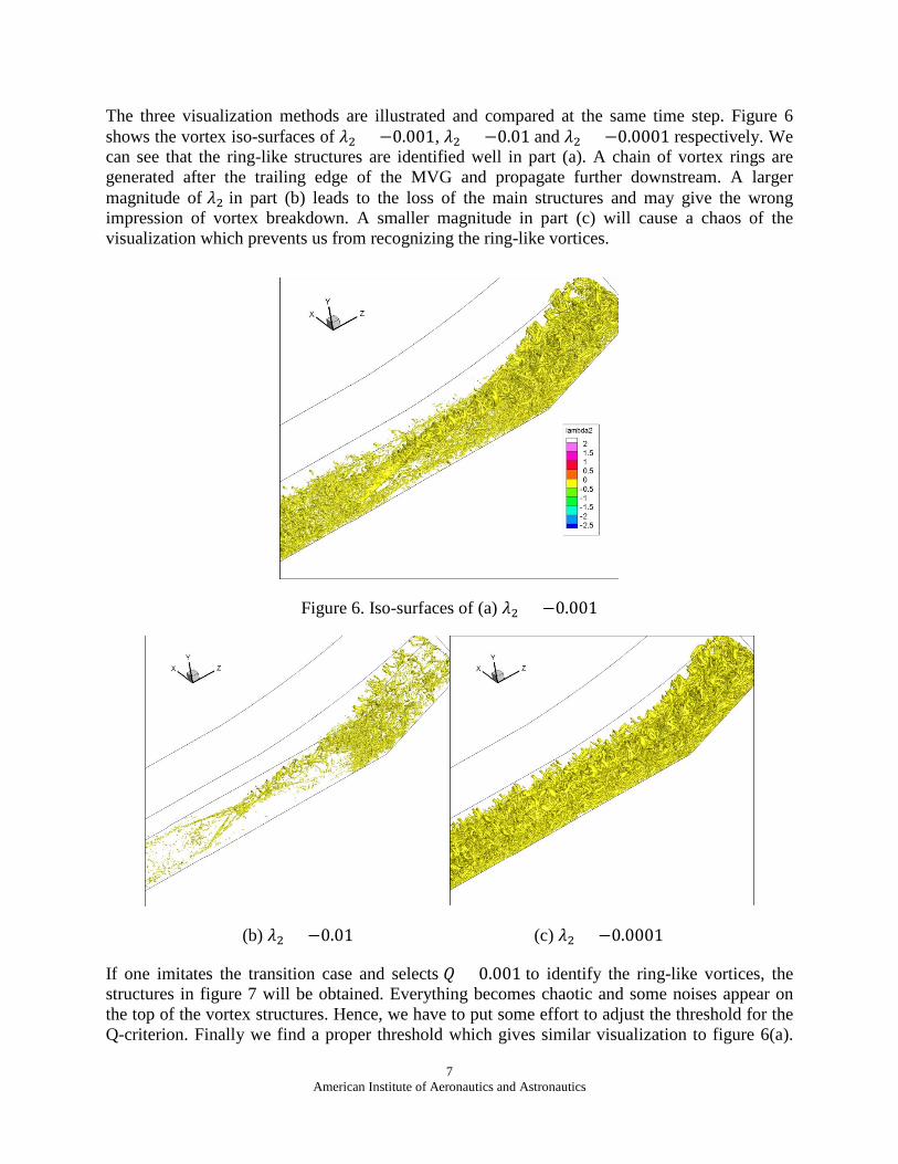
The three visualization methods are illustrated and compared at the same time step. Figure 6 shows the vortex iso-surfaces of 𝜆𝜆2 = −0.001, 𝜆𝜆2 = −0.01 and 𝜆𝜆2 = −0.0001 respectively. We can see that the ring-like structures are identified well in part (a). A chain of vortex rings are generated after the trailing edge of the MVG and propagate further downstream. A larger magnitude of 𝜆𝜆2 in part (b) leads to the loss of the main structures and may give the wrong impression of vortex breakdown. A smaller magnitude in part (c) will cause a chaos of the visualization which prevents us from recognizing the ring-like vortices.
Figure 6. Iso-surfaces of (a) 𝜆𝜆2 = −0.001
(b) 𝜆𝜆2 = −0.01 (c) 𝜆𝜆2 = −0.0001
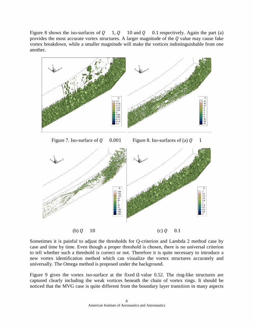
If one imitates the transition case and selects 𝑄𝑄 = 0.001 to identify the ring-like vortices, the structures in figure 7 will be obtained. Everything becomes chaotic and some noises appear on the top of the vortex structures. Hence, we have to put some effort to adjust the threshold for the Q-criterion. Finally we find a proper threshold which gives similar visualization to figure 6(a).
8 American Institute of Aeronautics and Astronautics
Figure 8 shows the iso-surfaces of 𝑄𝑄 = 1, 𝑄𝑄 = 10 and 𝑄𝑄 = 0.1 respectively. Again the part (a) provides the most accurate vortex structures. A larger magnitude of the 𝑄𝑄 value may cause fake vortex breakdown, while a smaller magnitude will make the vortices indistinguishable from one another.
Figure 7. Iso-surface of 𝑄𝑄 = 0.001 Figure 8. Iso-surfaces of (a) 𝑄𝑄 = 1
(b) 𝑄𝑄 = 10 (c) 𝑄𝑄 = 0.1
Sometimes it is painful to adjust the thresholds for Q-criterion and Lambda 2 method case by case and time by time. Even though a proper threshold is chosen, there is no universal criterion to tell whether such a threshold is correct or not. Therefore it is quite necessary to introduce a new vortex identification method which can visualize the vortex structures accurately and universally. The Omega method is proposed under the background.
Figure 9 gives the vortex iso-surface at the fixed Ω value 0.52. The ring-like structures are captured clearly including the weak vortices beneath the chain of vortex rings. It should be noticed that the MVG case is quite different from the boundary layer transition in many aspects

9 American Institute of Aeronautics and Astronautics
such as flow speed, compressibility and other conditions. Despite the differences, the Omega method still well captures the ring-like structures at the fixed threshold Ω = 0.52.
A fixed threshold and thus no need to adjust is a major advantage of the Omega method over the other two methods, which makes Omega the most effective and efficient tool in vortex identification.
Figure 9. Iso-surface of Ω = 0.52
3. Conclusion
From the above comparisons, we find the following advantages of the Omega method over the traditional Q-criterion and Lambda 2 method:
1) Omega method tries to give a mathematical definition that vortex is a region where Ω > 0.5.
2) Ω = 0.52 always well captures the vortex surface.
3) There is no need to select a “proper threshold” case by case, time by time or even area by area for the same case, which we really do not know “proper” or “improper” since we have no definition for “vortex”.
4) Omega method can capture both strong vortex and weak vortex without much adjustment.
Reference [1] S. K. Robinson, “Coherent Motions in the Turbulent Boundary Layer”, Annual Review of Fluid Mechanics 23, pp. 601-639, 1991 [2] C. Liu, Y. Wang, Y. Yang, and Z. Duan, “New Omega Vortex Identification Method,” Sci. CHINA Physics, Mech. Astron., Vol. 59, No. 8, pp. 684-711, 2016
10 American Institute of Aeronautics and Astronautics
[3] J. C. R. Hunt, A. A. Wray, and P. Moin, “Eddies, Streams, and Convergence Zones in Turbulent Flows” in Center for Turbulence Research, Proceedings of the Summer Program, pp. 193–208, 1988 [4] J. Jeong and F. Hussain, “On the Identification of a Vortex”, Journal of Fluid Mechanics 285, pp. 69-94, 1995 [5] B. Pierce, P. Moin, and T. Sayadi, “Application of Vortex Identification Schemes to Direct Numerical Simulation Data of a Transitional Boundary Layer”, Physics of Fluids 25, 015102, 2013 [6] C. Liu, Y. Yan, and P. Lu, “Physics of turbulence generation and sustenance in a boundary layer”, Computers & Fluids 102, 353-384 [7] Y. Yan, C. Chen, P. Lu, and C. Liu, “Study on Shock Wave-Vortex Ring Interaction by the Micro Vortex Generator controlled Ramp Flow with Turbulent Inflow”, Aerospace Science and Technology, 30: 226-231, 2013 [8] Q. Li, and C. Liu, “Implicit LES for Supersonic Microramp Vortex Generator: New Discoveries and New Mechanisms”, Modelling and Simulation in Engineering, Volume 2011, Article ID 934982