Direction Article Development of EFI for 4-stroke locomotive diesel ...
19
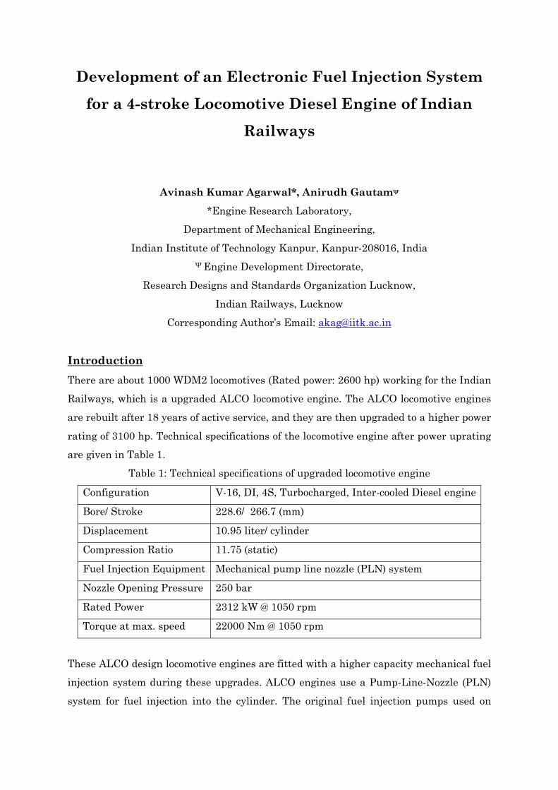
Development of an Electronic Fuel Injection System for a 4-stroke Locomotive Diesel Engine of Indian Railways Avinash Kumar Agarwal*, Anirudh Gautam ψ *Engine Research Laboratory, Department of Mechanical Engineering, Indian Institute of Technology Kanpur, Kanpur-208016, India Ψ Engine Development Directorate, Research Designs and Standards Organization Lucknow, Indian Railways, Lucknow Corresponding Author’s Email: [email protected] Introduction There are about 1000 WDM2 locomotives (Rated power: 2600 hp) working for the Indian Railways, which is a upgraded ALCO locomotive engine. The ALCO locomotive engines are rebuilt after 18 years of active service, and they are then upgraded to a higher power rating of 3100 hp. Technical specifications of the locomotive engine after power uprating are given in Table 1. Table 1: Technical specifications of upgraded locomotive engine Configuration V-16, DI, 4S, Turbocharged, Inter-cooled Diesel engine Bore/ Stroke 228.6/ 266.7 (mm) Displacement 10.95 liter/ cylinder Compression Ratio 11.75 (static) Fuel Injection Equipment Mechanical pump line nozzle (PLN) system Nozzle Opening Pressure 250 bar Rated Power 2312 kW @ 1050 rpm Torque at max. speed 22000 Nm @ 1050 rpm These ALCO design locomotive engines are fitted with a higher capacity mechanical fuel injection system during these upgrades. ALCO engines use a Pump-Line-Nozzle (PLN) system for fuel injection into the cylinder. The original fuel injection pumps used on
Transcript of Direction Article Development of EFI for 4-stroke locomotive diesel ...
Development of an Electronic Fuel Injection System
for a 4-stroke Locomotive Diesel Engine of Indian
Railways
Avinash Kumar Agarwal*, Anirudh Gautamψ
*Engine Research Laboratory,
Department of Mechanical Engineering,
Indian Institute of Technology Kanpur, Kanpur-208016, India
Ψ Engine Development Directorate,
Research Designs and Standards Organization Lucknow,
Indian Railways, Lucknow
Corresponding Author’s Email: [email protected]
Introduction
There are about 1000 WDM2 locomotives (Rated power: 2600 hp) working for the Indian
Railways, which is a upgraded ALCO locomotive engine. The ALCO locomotive engines
are rebuilt after 18 years of active service, and they are then upgraded to a higher power
rating of 3100 hp. Technical specifications of the locomotive engine after power uprating
are given in Table 1.
Table 1: Technical specifications of upgraded locomotive engine
Configuration V-16, DI, 4S, Turbocharged, Inter-cooled Diesel engine
Bore/ Stroke 228.6/ 266.7 (mm)
Displacement 10.95 liter/ cylinder
Compression Ratio 11.75 (static)
Fuel Injection Equipment Mechanical pump line nozzle (PLN) system
Nozzle Opening Pressure 250 bar
Rated Power 2312 kW @ 1050 rpm
Torque at max. speed 22000 Nm @ 1050 rpm
These ALCO design locomotive engines are fitted with a higher capacity mechanical fuel
injection system during these upgrades. ALCO engines use a Pump-Line-Nozzle (PLN)
system for fuel injection into the cylinder. The original fuel injection pumps used on
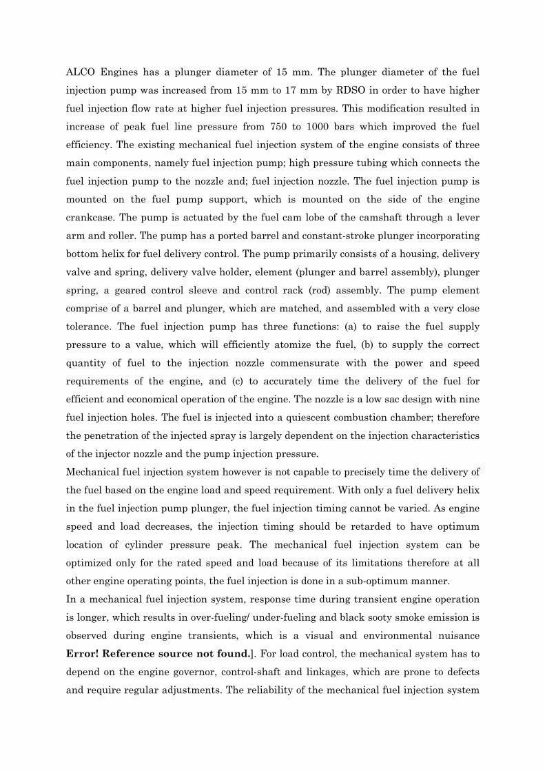
ALCO Engines has a plunger diameter of 15 mm. The plunger diameter of the fuel
injection pump was increased from 15 mm to 17 mm by RDSO in order to have higher
fuel injection flow rate at higher fuel injection pressures. This modification resulted in
increase of peak fuel line pressure from 750 to 1000 bars which improved the fuel
efficiency. The existing mechanical fuel injection system of the engine consists of three
main components, namely fuel injection pump; high pressure tubing which connects the
fuel injection pump to the nozzle and; fuel injection nozzle. The fuel injection pump is
mounted on the fuel pump support, which is mounted on the side of the engine
crankcase. The pump is actuated by the fuel cam lobe of the camshaft through a lever
arm and roller. The pump has a ported barrel and constant-stroke plunger incorporating
bottom helix for fuel delivery control. The pump primarily consists of a housing, delivery
valve and spring, delivery valve holder, element (plunger and barrel assembly), plunger
spring, a geared control sleeve and control rack (rod) assembly. The pump element
comprise of a barrel and plunger, which are matched, and assembled with a very close
tolerance. The fuel injection pump has three functions: (a) to raise the fuel supply
pressure to a value, which will efficiently atomize the fuel, (b) to supply the correct
quantity of fuel to the injection nozzle commensurate with the power and speed
requirements of the engine, and (c) to accurately time the delivery of the fuel for
efficient and economical operation of the engine. The nozzle is a low sac design with nine
fuel injection holes. The fuel is injected into a quiescent combustion chamber; therefore
the penetration of the injected spray is largely dependent on the injection characteristics
of the injector nozzle and the pump injection pressure.
Mechanical fuel injection system however is not capable to precisely time the delivery of
the fuel based on the engine load and speed requirement. With only a fuel delivery helix
in the fuel injection pump plunger, the fuel injection timing cannot be varied. As engine
speed and load decreases, the injection timing should be retarded to have optimum
location of cylinder pressure peak. The mechanical fuel injection system can be
optimized only for the rated speed and load because of its limitations therefore at all
other engine operating points, the fuel injection is done in a sub-optimum manner.
In a mechanical fuel injection system, response time during transient engine operation
is longer, which results in over-fueling/ under-fueling and black sooty smoke emission is
observed during engine transients, which is a visual and environmental nuisance
Error! Reference source not found.]. For load control, the mechanical system has to
depend on the engine governor, control-shaft and linkages, which are prone to defects
and require regular adjustments. The reliability of the mechanical fuel injection system
is also therefore adversely affected due to large number of such moving parts. By
machining an additional helix on the top of the plunger (top helix), some fixed control of
the injection timing was achieved Error! Reference source not found.]. However
with an electronic fuel injection system, there is complete flexibility in varying the start
of fuel delivery to obtain an optimum pressure curve and low smoke opacity theoretically
Error! Reference source not found.] and electronic fuel injection systems also offer
enormous flexibility to the process of fuel injection. In view of all these advantages
offered by electronic fuel injection system, it was decided to experiment retrofitting
ALCO WDM2 locomotives with Electronically Controlled Fuel Injection system (EFI)
during the mid-life rebuilding.
Background
In view of the advantages offered by an electronic fuel injection system in comparison to
mechanical fuel injection system, a collaborative research project by the Engine
Development Directorate, Research Designs and Standards Organization under the
Ministry of Railways and Engine Research Laboratory (ERL), Indian Institute of
Technology Kanpur was conceptualized. IIT Kanpur was contacted by EDD, RDSO to
help them develop Electronic Fuel injection System for the ALCO DLW Locomotive
series, which is the main workhorse of the Indian Railways. The collaboration started in
year 2010 with major focus on developing an interface of the EFI system with the engine
test cells at RDSO for optimization of the engine and calibration of the ECU and for
interfacing and integration of the EFI system to the locomotive traction control system
and assist RDSO in overall integration of the EFI system on to a diesel locomotive.
Engine Research Laboratory of IIT Kanpur undertook this work and delivered the EFI
for the Locomotive successfully in association with EDD, RDSO in less than 4 months.
Project Objectives
Following project objectives were identified for this collaborative project to be executed
by ERL, IIT Kanpur:
Design and development of a suitable hardware and software for interfacing of EFI
system to the AVL make control test stand in the Engine Development Directorate
at RDSO.
Assist RDSO in the optimization of the engine and ECU calibration in solving
problems associated with integrated load and speed control of the engine.
Design and develop suitable hardware and software for integrating the EFI system
to a locomotive traction control system for fitment on a diesel locomotive.
Provide support to RDSO and DMW Patiala teams during the integration of EFI
onto the prototype diesel locomotive.
Trouble-shoot any problems reported during the field trials of the locomotive.
Implementation
Design and development of hardware and software for the project were carried out by
ERL, IIT Kanpur with close involvement of Engine Development Directorate, RDSO,
Lucknow.
As a first step, a detailed study of the AVL test bed control system was done. A conflict
in the communication protocols between the AVL system and Heinzmann ECU was
discovered. This was set right by developing a suitable design of hardware and software.
An interface box was manufactured by ERL with these specifications. The AVL test
controller did not specify the ports to be used for external communication, therefore
special efforts were made to configure a port to be able to communicate to the
Heinzmann ECU. After installing the interfacing box, problems were rectified and an
integrated control of engine speed and load was established on the Test-bed. Engine was
operated and optimized at each engine load and speed point and the ECU calibrated
accordingly. After successful calibration of the ECU on the engine test bed, attention
was focused towards designing and developing an interfacing hardware and software for
installation of the EFI on a diesel locomotive. This was done by ERL in a record time
and the Engine Development Directorate team successfully completed the trials on
running a diesel locomotive at Alambagh diesel shed, Lucknow. Three shift working for
close to two weeks were required to initially establish the efficacy of the interfacing box
design on the locomotive. Based on the inputs received during ‘dry run’ of the EFI on a
locomotive at Alambagh diesel shed, further design modifications were carried out on
the system and a new interfacing box was manufactured for fitment on the prototype
diesel locomotive at DMW Patiala. At DMW, ERL team supervised the fitment of the
interfacing box on the locomotive and provided valuable assistance to the RDSO and
DMW team in integrating the complete system on the locomotive and finally made a
working proto-type. First prototype diesel locomotive was finally flagged off from DMW
in the month September 2010.
System Overview
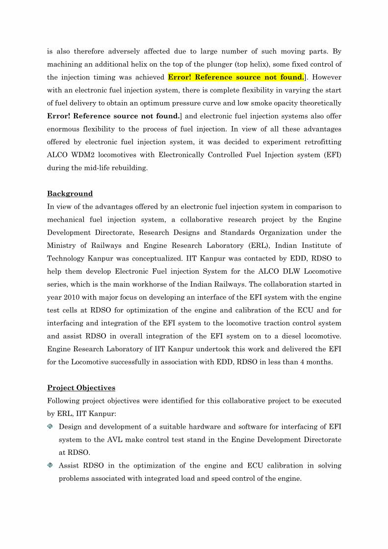
Figure 1: Block Diagram of the EFI system integrated to Locomotive Control System
Error! Reference source not found.Figure 1 shows the block diagram of the
electronically controlled fuel injection system as fitted on the locomotive. Parameters
such as engine speed, cam position, engine boost air pressure, lubricating oil pressure
and coolant temperature are acquired by the engine control unit (ECU). Engine fueling
is controlled by the ECU by systematically energizing the magnetic valves fitted on the
fuel injection pumps. Drive to the fuel injection pump is through the camshaft and a
lever mechanismError! Reference source not found.. A schematic of the PLN system
is shown in figure 2.
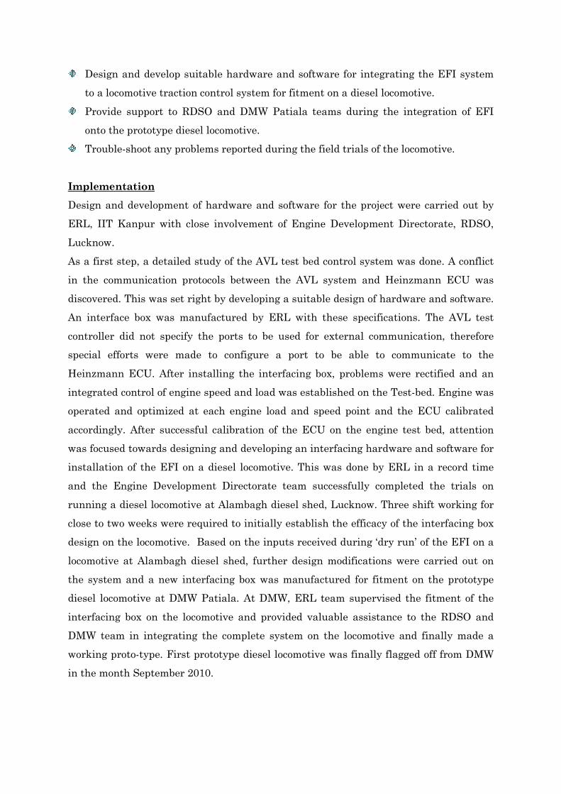
Figure 2: Pump Pipe Nozzle System of Indian Railway’s ALCO DLW Locomotives
The diesel engine on the locomotive is mechanically coupled to an alternator. Electrical
power generated by the alternator is used by the traction motors fitted on the locomotive
axles to provide traction power to the diesel locomotive. The load on the engine is
controlled by varying the field current of the alternator; engine fuelling and speed is
controlled by the ECU. In response to the driver’s notch handle and /or road conditions,
the loading and fuelling of the engine are varied to maintain a pre-determined engine
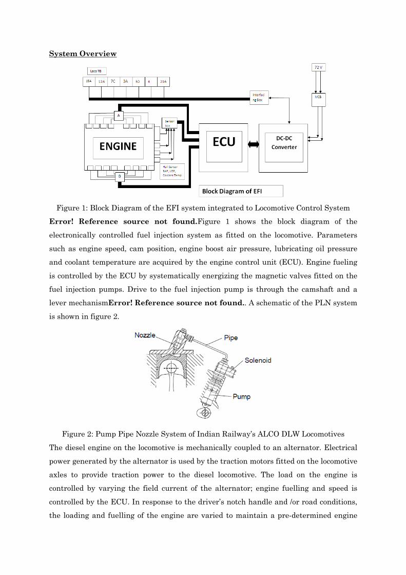
speed at each engine notch. There are nine engine notches, starting from Idle to the 8th
engine notch having specific engine speed and power output. The power, torque
generated by the engine vis-à-vis engine speed for the locomotive is shown in Figure 3.
0
5000
10000
15000
20000
300 500 700 900 1100Engine S peed (rpm)
To
rqu
e (
Nm
)
0
500
1000
1500
2000
2500
Po
we
r (k
W)
Torque
Power
Figure 3: Engine torque, power and speed at different engine notches Error! Reference
source not found.]
Using EFI, it is possible to adjust the fuel injection timing according to varying load and
speed conditions of the engine dynamically so as to achieve extremely low fuel
consumption and efficient engine operation with lowest pollution Error! Reference
source not found.]. These tasks cannot be performed by a mechanical fuel injection
system. The advantages of EFI system over mechanical fuel injection system include:
(a) digital setting of parameters, (b) precise and dynamic control of injection timings,
injection duration, (c) elimination of mechanical hardware, (d) protection of engine, (e)
online fault diagnostics, display and logging of faults, (f) optimized fuel injection for each
cylinder and every engine operating point depending on load and speed condition, (g)
reduction in smoke opacity levels and particulate matter, (h) possibility of cut-off of fuel
to individual cylinders, and (i) protection against hot engine, automatic cut-off of load
and fuel and enhanced safety and flexibility.
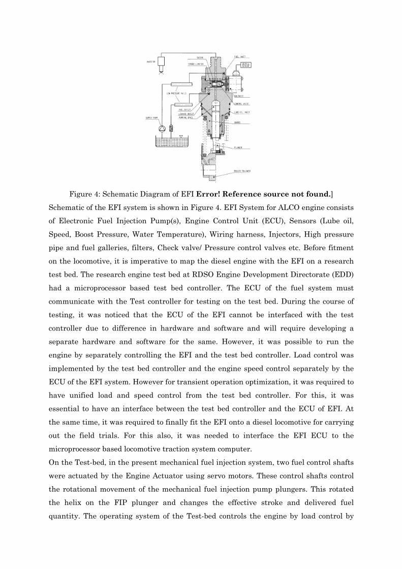
Figure 4: Schematic Diagram of EFI Error! Reference source not found.]
Schematic of the EFI system is shown in Figure 4. EFI System for ALCO engine consists
of Electronic Fuel Injection Pump(s), Engine Control Unit (ECU), Sensors (Lube oil,
Speed, Boost Pressure, Water Temperature), Wiring harness, Injectors, High pressure
pipe and fuel galleries, filters, Check valve/ Pressure control valves etc. Before fitment
on the locomotive, it is imperative to map the diesel engine with the EFI on a research
test bed. The research engine test bed at RDSO Engine Development Directorate (EDD)
had a microprocessor based test bed controller. The ECU of the fuel system must
communicate with the Test controller for testing on the test bed. During the course of
testing, it was noticed that the ECU of the EFI cannot be interfaced with the test
controller due to difference in hardware and software and will require developing a
separate hardware and software for the same. However, it was possible to run the
engine by separately controlling the EFI and the test bed controller. Load control was
implemented by the test bed controller and the engine speed control separately by the
ECU of the EFI system. However for transient operation optimization, it was required to
have unified load and speed control from the test bed controller. For this, it was
essential to have an interface between the test bed controller and the ECU of EFI. At
the same time, it was required to finally fit the EFI onto a diesel locomotive for carrying
out the field trials. For this also, it was needed to interface the EFI ECU to the
microprocessor based locomotive traction system computer.
On the Test-bed, in the present mechanical fuel injection system, two fuel control shafts
were actuated by the Engine Actuator using servo motors. These control shafts control
the rotational movement of the mechanical fuel injection pump plungers. This rotated
the helix on the FIP plunger and changes the effective stroke and delivered fuel
quantity. The operating system of the Test-bed controls the engine by load control by
hydraulic dynamometer control and engine speed by fuel control through the fuel
actuator. The system has a number of channels for analog and digital inputs and
outputs.
The requirement was to interface the ECU to the operating system of the test cell
controller such that test cell controller can control the ECU. Since the ECU is
controlling the speed of the engine, the way to send the speed set value from the test cell
controller to the ECU had to be found.
Locomotive ECU Calibration
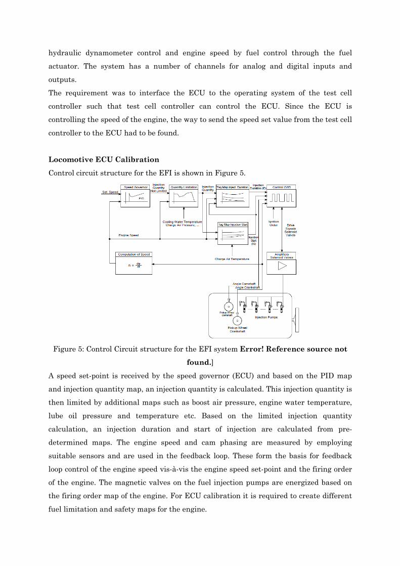
Control circuit structure for the EFI is shown in Figure 5.
Figure 5: Control Circuit structure for the EFI system Error! Reference source not
found.]
A speed set-point is received by the speed governor (ECU) and based on the PID map
and injection quantity map, an injection quantity is calculated. This injection quantity is
then limited by additional maps such as boost air pressure, engine water temperature,
lube oil pressure and temperature etc. Based on the limited injection quantity
calculation, an injection duration and start of injection are calculated from pre-
determined maps. The engine speed and cam phasing are measured by employing
suitable sensors and are used in the feedback loop. These form the basis for feedback
loop control of the engine speed vis-à-vis the engine speed set-point and the firing order
of the engine. The magnetic valves on the fuel injection pumps are energized based on
the firing order map of the engine. For ECU calibration it is required to create different
fuel limitation and safety maps for the engine.
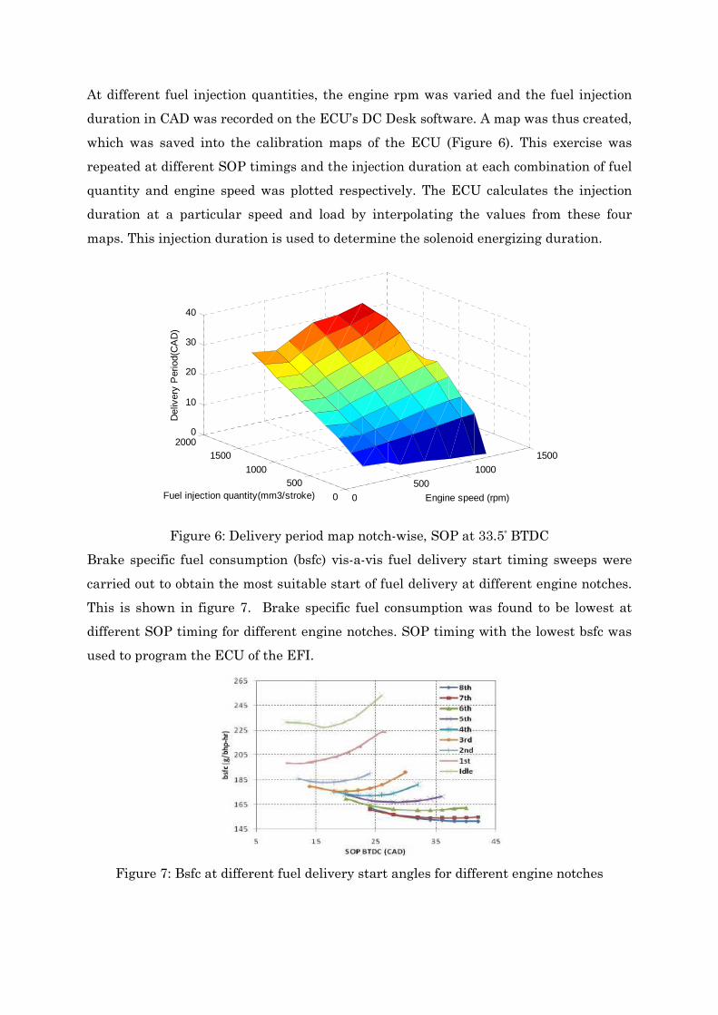
At different fuel injection quantities, the engine rpm was varied and the fuel injection
duration in CAD was recorded on the ECU’s DC Desk software. A map was thus created,
which was saved into the calibration maps of the ECU (Figure 6). This exercise was
repeated at different SOP timings and the injection duration at each combination of fuel
quantity and engine speed was plotted respectively. The ECU calculates the injection
duration at a particular speed and load by interpolating the values from these four
maps. This injection duration is used to determine the solenoid energizing duration.
0
500
1000
1500
0
5001000
15002000
0
10
20
30
40
Engine speed (rpm)Fuel injection quantity(mm3/stroke)
Del
iver
y P
erio
d(C
AD
)
Figure 6: Delivery period map notch-wise, SOP at 33.5º BTDC
Brake specific fuel consumption (bsfc) vis-a-vis fuel delivery start timing sweeps were
carried out to obtain the most suitable start of fuel delivery at different engine notches.
This is shown in figure 7. Brake specific fuel consumption was found to be lowest at
different SOP timing for different engine notches. SOP timing with the lowest bsfc was
used to program the ECU of the EFI.
Figure 7: Bsfc at different fuel delivery start angles for different engine notches
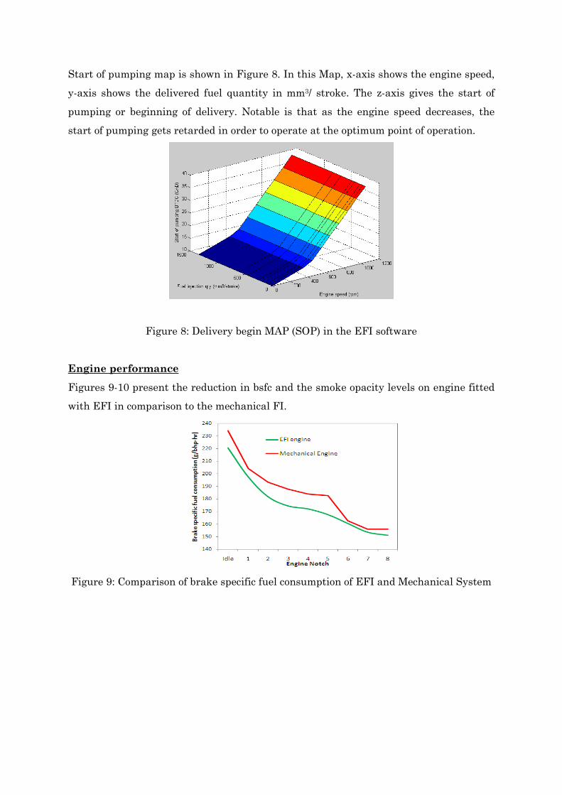
Start of pumping map is shown in Figure 8. In this Map, x-axis shows the engine speed,
y-axis shows the delivered fuel quantity in mm3/ stroke. The z-axis gives the start of
pumping or beginning of delivery. Notable is that as the engine speed decreases, the
start of pumping gets retarded in order to operate at the optimum point of operation.
Figure 8: Delivery begin MAP (SOP) in the EFI software
Engine performance
Figures 9-10 present the reduction in bsfc and the smoke opacity levels on engine fitted
with EFI in comparison to the mechanical FI.
Figure 9: Comparison of brake specific fuel consumption of EFI and Mechanical System
0
5
10
15
20
25
30
35
40
45
50
Idle 1 2 3 4 5 6 7 8
Smok
e O
paci
ty (
%)
Engine Notch
EFI engine
Mechanical Engine
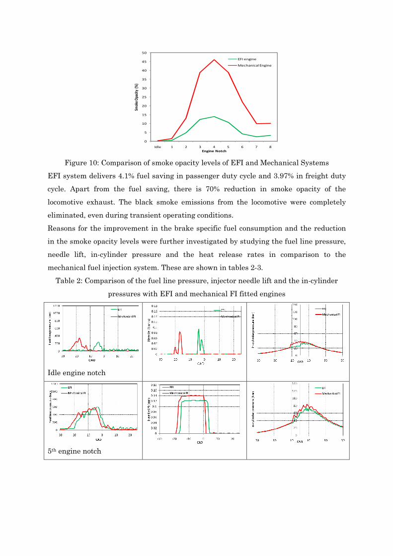
Figure 10: Comparison of smoke opacity levels of EFI and Mechanical Systems
EFI system delivers 4.1% fuel saving in passenger duty cycle and 3.97% in freight duty
cycle. Apart from the fuel saving, there is 70% reduction in smoke opacity of the
locomotive exhaust. The black smoke emissions from the locomotive were completely
eliminated, even during transient operating conditions.
Reasons for the improvement in the brake specific fuel consumption and the reduction
in the smoke opacity levels were further investigated by studying the fuel line pressure,
needle lift, in-cylinder pressure and the heat release rates in comparison to the
mechanical fuel injection system. These are shown in tables 2-3.
Table 2: Comparison of the fuel line pressure, injector needle lift and the in-cylinder
pressures with EFI and mechanical FI fitted engines
Idle engine notch
5th engine notch
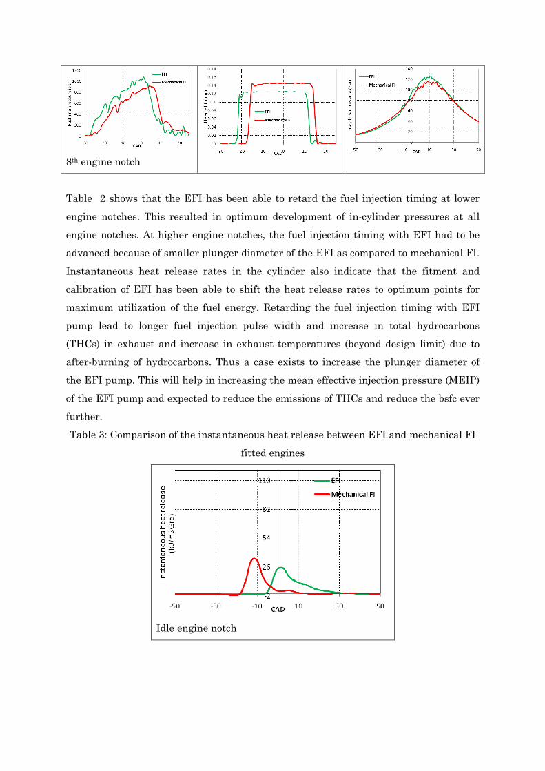
8th engine notch
Table 2 shows that the EFI has been able to retard the fuel injection timing at lower
engine notches. This resulted in optimum development of in-cylinder pressures at all
engine notches. At higher engine notches, the fuel injection timing with EFI had to be
advanced because of smaller plunger diameter of the EFI as compared to mechanical FI.
Instantaneous heat release rates in the cylinder also indicate that the fitment and
calibration of EFI has been able to shift the heat release rates to optimum points for
maximum utilization of the fuel energy. Retarding the fuel injection timing with EFI
pump lead to longer fuel injection pulse width and increase in total hydrocarbons
(THCs) in exhaust and increase in exhaust temperatures (beyond design limit) due to
after-burning of hydrocarbons. Thus a case exists to increase the plunger diameter of
the EFI pump. This will help in increasing the mean effective injection pressure (MEIP)
of the EFI pump and expected to reduce the emissions of THCs and reduce the bsfc ever
further.
Table 3: Comparison of the instantaneous heat release between EFI and mechanical FI
fitted engines
Idle engine notch
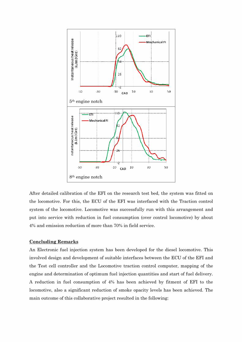
5th engine notch
8th engine notch
After detailed calibration of the EFI on the research test bed, the system was fitted on
the locomotive. For this, the ECU of the EFI was interfaced with the Traction control
system of the locomotive. Locomotive was successfully run with this arrangement and
put into service with reduction in fuel consumption (over control locomotive) by about
4% and emission reduction of more than 70% in field service.
Concluding Remarks
An Electronic fuel injection system has been developed for the diesel locomotive. This
involved design and development of suitable interfaces between the ECU of the EFI and
the Test cell controller and the Locomotive traction control computer, mapping of the
engine and determination of optimum fuel injection quantities and start of fuel delivery.
A reduction in fuel consumption of 4% has been achieved by fitment of EFI to the
locomotive, also a significant reduction of smoke opacity levels has been achieved. The
main outcome of this collaborative project resulted in the following:
1. Development of Electronic Fuel Injection for the ALCO Locomotive, to replace the
widely used mechanical injection system, which makes precise injection of fuel
possible to match the demand of load, optimize fuel consumption and cuts down
emissions.
2. Saving of 4% of High Speed Diesel over the duty cycle of the diesel locomotive. This
is over and above that achieved due to upgrades already made on the locomotives.
The potential saving is enormous, considering the Indian Railways consume nearly
250 Crore litres of fuel costing approximately Rs 13,000 Crores.
3. Complete elimination of black smoke from locomotive engine. This not only saves the
environment, but also saves fuel, since black smoke is caused by incompletely burnt
fuel.
4. Elimination of hot engine failures of the locomotives.
5. Elimination of large number of mechanical components, reduction in maintenance
and increase in reliability.
6. Better control and diagnostics.
This fete is achieved purely indigenously due to collaborative efforts of RDSO and IIT
Kanpur. This landmark project heralds “greening” of diesel traction in the true sense. It
also marks the culmination of the synergic teamwork of industry and academia
previously unseen on Indian Railways and opens the doors to numerous such possible
collaborations in the future.
References
[1]. Flis T.J., ‘The Use of Microprocessors for Electronic Engine Control, IEEE
transactions on Industrial Electronics, Vol. IE-30, No. 2, May 1983]
[2]. Kathpal A.K., Gautam A., Agarwal Avinash K., Baskaran R., ‘Design and
development of double helix fuel injection pump for four stroke V-16 rail traction
diesel engine’, ICEF 2007-1651, Proceedings of the ASME Internal Combustion
Engine Division, Fall Technical Conference, Oct 14-17, 2007.
[3]. Nakai Hiroaki, Konishi Yukio, Fukushima Akira, ‘An electronically controlled fuel
injection system for new diesel engines’, JSAE Review 18 (1997) 57-82.
[4]. Power uprating of ALCO engine, Engine Development Directorate, RDSO internal
report, 2000.
[5]. Bosch India presentation, 2011.
[6]. Interfacing of EFI to Test controller and to the diesel locomotive, RDSO Engine
Development internal report, 2011.
[7]. Reduction of exhaust emissions from diesel locomotives of Indian Railways, RDSO
Engine Development Directorate internal report, 2009.
Contacts
Prof. Avinash Kumar Agarwal joined Department of Mechanical Engineering, Indian
Institute of Technology Kanpur in 2001. His areas of interest are IC engines,
combustion, alternative fuels, biodiesel, alcohol, natural gas, hydrogen, conventional
fuels, lubricating oil tribology, emission control, optical diagnostic techniques, laser
ignition, HCCI, particulates, micro-sensors, and large bore engines. Prof. Agarwal has
recently been designated as Fellow of SAE International, USA in class of 2013. He is
recipient of several prestigious national and international awards such as “NASI-
Reliance Industries Platinum Jubilee Award-2012” for Application Oriented Innovations
in Physical Sciences; INAE Silver Jubilee Young Engineer Award-2012; Dr. C. V.
Raman Young Teachers Award: 2011 for Excellence in the field of Engineering
Education; SAE International’s Ralph R. Teetor Educational Award -2008; INSA Young
Scientist Award-2007; UICT Young Scientist Award-2007 by University Institute of
Chemical Technology, Mumbai; INAE Young Engineer Award-2005; AICTE Career
Award for Young Tecahers-2004; DST Young Scientist Award-2002; and DST
BOYSCAST Fellowship. IIT Kanpur recognized him as “Poonam and Prabhu Goyal
Chair Professor (2013-16)” for his contributions in the field of Energy.
Email: [email protected]; Ph: 0512-259-7982
Dr. Anirudh Gautam is Executive Director (Engine Development) at RDSO, Lucknow.
He is working for Indian Railways Service (Mechanical Engineers) since 1986. Dr.
Gautam joined Indian Railways as a special class railway apprentice (SCRA 1983 batch)
at Jamalpur. Dr. Gautam received his M.E. in Engine Systems from University of
Wisconsin, Madison, USA in 2010 and he obtained his PhD in IC Engines from IIT
Kanpur in 2013. He developed the first hotel load diesel locomotive for export and
carried out the indigenisation of the EMD locomotive technology at DLW. Dr. Gautam
was also responsible for upgradation of horsepower of EMD locomotives from 4000 hp to
4500 hp. Dr. Gautam has been actively involved in the IR projects on alternate fuels and
emission reduction of diesel locomotives. He is currently working on development of dual
fuel CNG diesel locomotive for IR.
Email: [email protected]; Ph: 9794863148
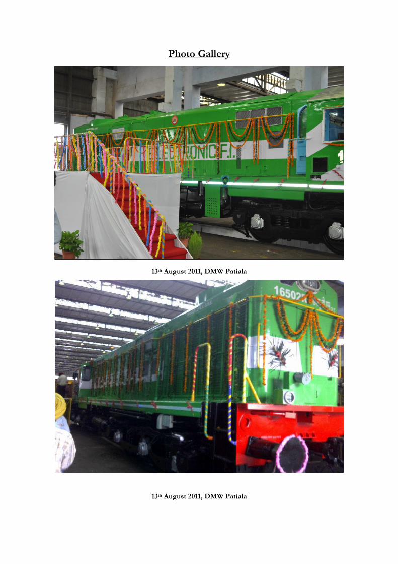
Photo Gallery
13th August 2011, DMW Patiala
13th August 2011, DMW Patiala
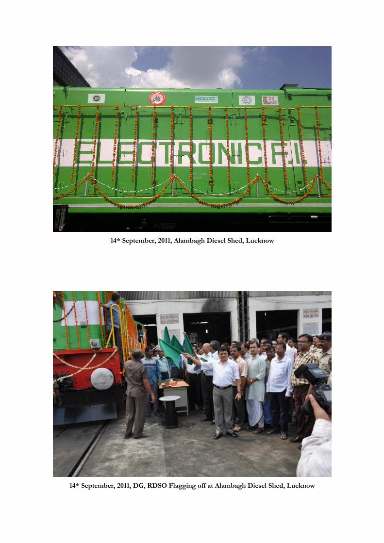
14th September, 2011, Alambagh Diesel Shed, Lucknow
14th September, 2011, DG, RDSO Flagging off at Alambagh Diesel Shed, Lucknow