Dimensions Chassis DynamometerDimensions (unit in mm) Chassis dynamometer AC Drive for dynamometers...
5
Chassis Dynamometer
Transcript of Dimensions Chassis DynamometerDimensions (unit in mm) Chassis dynamometer AC Drive for dynamometers...
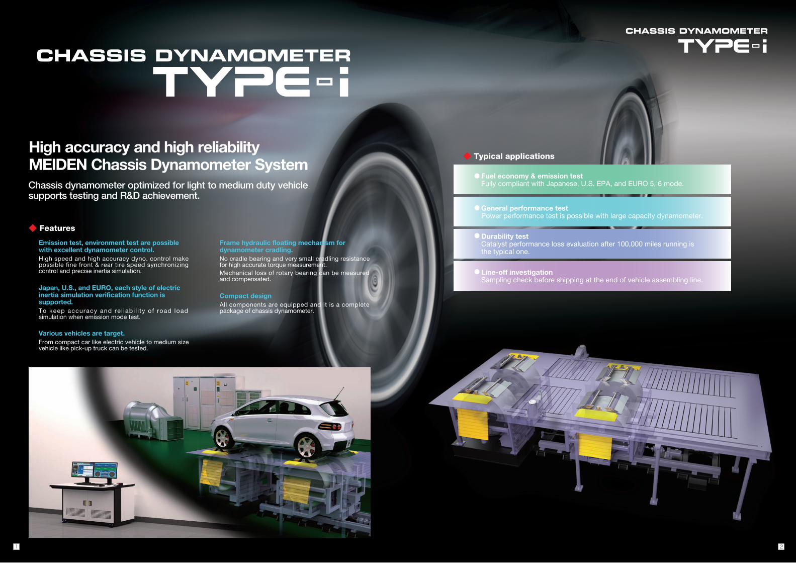
Dimensions (unit in mm)
◆ Chassis dynamometer
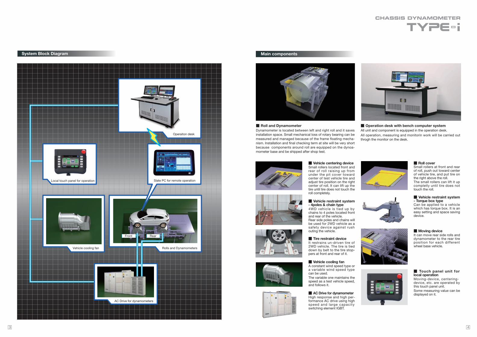
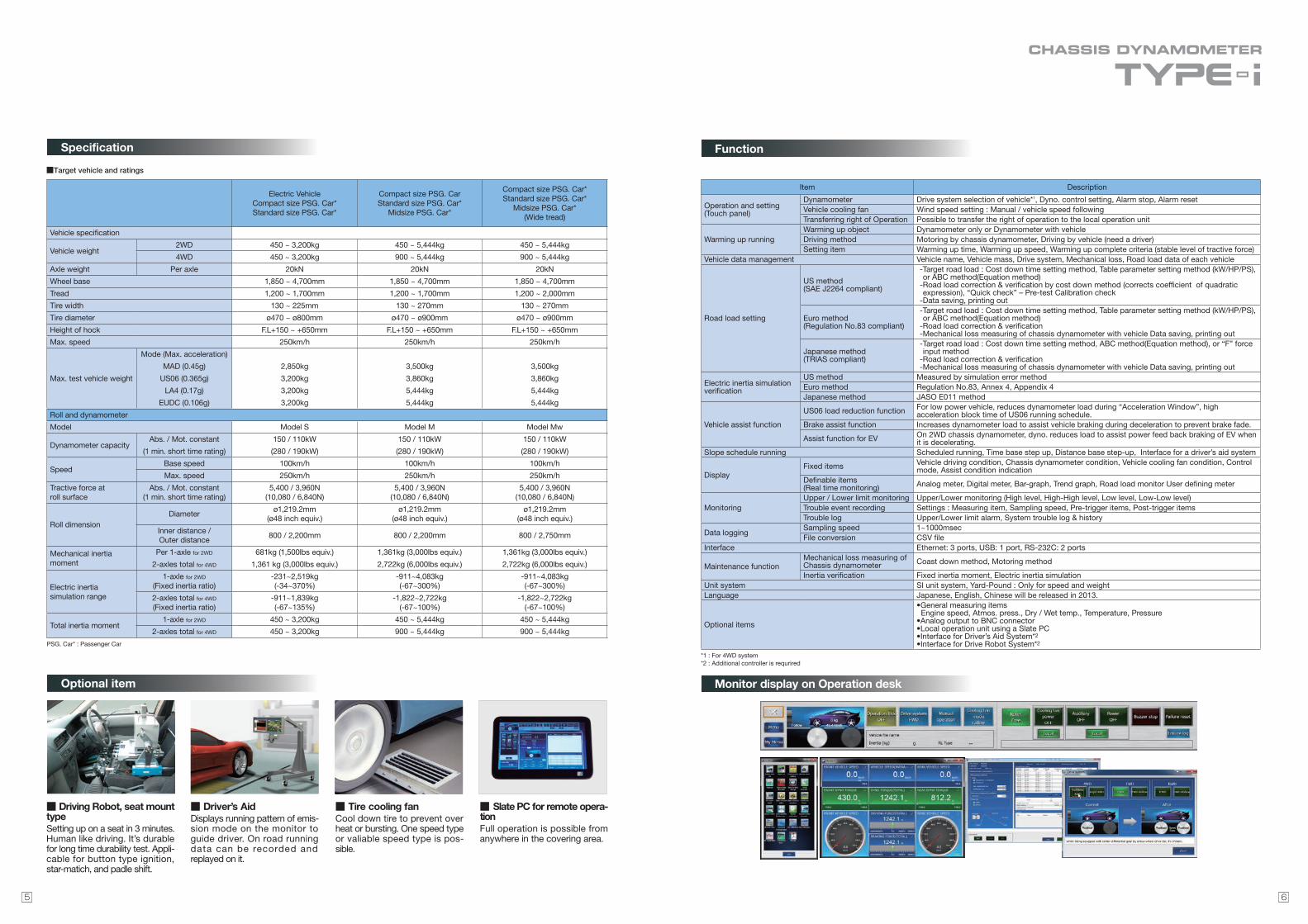
◆ AC Drive for dynamometers ◆ Vehicle cooling fan
8400
1850
750
(Max. wheel base) 4700(Min. wheel base)
1850(Moving length) 2850
1850
82.5 3835 82.5
250 3500 250
4000
2200
Rear roll back end position
Power line inlet
Output filter
Rear roll front end position Front roll center position
φ97
5
1130200210 730 200475
1625
3400 600 600 600 600
1150
500
500
1000
2100
1650
600F2
Chassis Dynamometer
Specifications in this catalog are subject to change without notice. CE97-3221A As of May, 20182018-5ME(3.6L)0.5L
ThinkPark Tower, 2-1-1, Osaki, Shinagawa-ku, Tokyo, 141-6029 Japan
Phone: 81-3-6420-7750 Facsimile: 81-3-5745-3053
www.meidensha.com
◆ Typical applications
High accuracy and high reliabilityMEIDEN Chassis Dynamometer SystemChassis dynamometer optimized for light to medium duty vehiclesupports testing and R&D achievement.
◆ Features
Emission test, environment test are possible with excellent dynamometer control.High speed and high accuracy dyno. control make possible fine front & rear tire speed synchronizing control and precise inertia simulation.
Japan, U.S., and EURO, each style of electric inertia simulation verification function is supported.To keep accuracy and rel iabi l i ty of road load simulation when emission mode test.
Various vehicles are target.From compact car like electric vehicle to medium size vehicle like pick-up truck can be tested.
Frame hydraulic floating mechanism for dynamometer cradling.No cradle bearing and very small cradling resistance for high accurate torque measurement.Mechanical loss of rotary bearing can be measured and compensated.
Compact designAll components are equipped and it is a complete package of chassis dynamometer.
Fuel economy & emission testFully compliant with Japanese, U.S. EPA, and EURO 5, 6 mode.
●
General performance testPower performance test is possible with large capacity dynamometer.
●
Durability testCatalyst performance loss evaluation after 100,000 miles running is the typical one.
●
Line-off investigationSampling check before shipping at the end of vehicle assembling line.
●
21
Main componentsSystem Block Diagram
■ Vehicle centering deviceSmall rollers located front and rear of roll raising up from under the pit cover toward center of test vehicle tire and adjust tire position on the right center of roll. It can lift up the tire until tire does not touch the roll completely.
■ Vehicle restraint system - 4poles & chain type4WD vehicle is t ied up by chains to 4 poles located front and rear of the vehicle.Rear side poles and chains will be used for 2WD vehicle as a safety device against rush outing the vehicle.
■ Tire restraint deviceIt restrains un-driven tire of 2WD vehicle. The tire is tied down by belt to the tire stop-pers at front and rear of it.
■ Vehicle cooling fanA constant wind speed type or a variable wind speed type can be used. The variable one maintains the speed as a test vehicle speed, and follows it.
■ AC Drive for dynamometerHigh response and high per-formance AC drive using high speed and large capacity switching element IGBT.
■ Roll coverSmall rollers at front and rear of roll, push out toward center of vehicle tire, and put tire on the right above the roll.The small rollers can lift it up completly until tire does not touch the roll.
■ Vehicle restraint system - Torque box typeCan be applied to a vehicle which has torque box. It is an easy setting and space saving device.
■ Moving deviceIt can move rear side rolls and dynamometer to the rear tire position for each different wheel base vehicle.
■ Touch panel unit for local operationMoving-device, centering-device, etc. are operated by this touch panel unit.Some measuring value can be displayed on it.
①タイヤ拘束式(2輪駆動専用)
■ Roll and DynamometerDynamometer is located between left and right roll and it saves installation space. Small mechanical loss of rotary bearing can be measured and managed because of the frame floating mecha-nism. Installation and final checking term at site will be very short because components around roll are equipped on the dynoa-mometer base and be shipped after shop test.
■ Operation desk with bench computer systemAll unit and component is equipped in the operation desk.All operation, measuring and monitorin work will be carried out throgh the monitor on the desk.
Operaiton desk
Local touch panel for operation
Vehicle cooling fan Rolls and Dynamometers
Slate PC for remote operation
AC Drive for dynamometers
Fuel economy & emission testFully compliant with Japanese, U.S. EPA and EURO 5, 6 mode.
Front Rear
43
■Target vehicle and ratings
Function
Monitor display on Operation desk
Specification
Optional item
■ Driving Robot, seat mount typeSetting up on a seat in 3 minutes. Human like driving. It’s durable for long time durability test. Appli-cable for button type ignition, star-matich, and padle shift.
■ Driver’s AidDisplays running pattern of emis-sion mode on the monitor to guide driver. On road running data can be recorded and replayed on it.
■ Tire cooling fanCool down tire to prevent over heat or bursting. One speed type or valiable speed type is pos-sible.
■ Slate PC for remote opera-tionFull operation is possible from anywhere in the covering area.
Electric VehicleCompact size PSG. Car*Standard size PSG. Car*
Compact size PSG. CarStandard size PSG. Car*
Midsize PSG. Car*
Compact size PSG. Car*Standard size PSG. Car*
Midsize PSG. Car*(Wide tread)
Vehicle specification
Vehicle weight2WD 450 ~ 3,200kg 450 ~ 5,444kg 450 ~ 5,444kg
4WD 450 ~ 3,200kg 900 ~ 5,444kg 900 ~ 5,444kg
Axle weight Per axle 20kN 20kN 20kN
Wheel base 1,850 ~ 4,700mm 1,850 ~ 4,700mm 1,850 ~ 4,700mm
Tread 1,200 ~ 1,700mm 1,200 ~ 1,700mm 1,200 ~ 2,000mm
Tire width 130 ~ 225mm 130 ~ 270mm 130 ~ 270mm
Tire diameter ø470 ~ ø800mm ø470 ~ ø900mm ø470 ~ ø900mm
Height of hock F.L+150 ~ +650mm F.L+150 ~ +650mm F.L+150 ~ +650mm
Max. speed 250km/h 250km/h 250km/h
Max. test vehicle weight
Mode (Max. acceleration)
MAD (0.45g) 2,850kg 3,500kg 3,500kg
US06 (0.365g) 3,200kg 3,860kg 3,860kg
LA4 (0.17g) 3,200kg 5,444kg 5,444kg
EUDC (0.106g) 3,200kg 5,444kg 5,444kg
Roll and dynamometer
Model Model S Model M Model Mw
Dynamometer capacityAbs. / Mot. constant 150 / 110kW 150 / 110kW 150 / 110kW
(1 min. short time rating) (280 / 190kW) (280 / 190kW) (280 / 190kW)
SpeedBase speed 100km/h 100km/h 100km/h
Max. speed 250km/h 250km/h 250km/h
Tractive force atroll surface
Abs. / Mot. constant(1 min. short time rating)
5,400 / 3,960N(10,080 / 6,840N)
5,400 / 3,960N(10,080 / 6,840N)
5,400 / 3,960N(10,080 / 6,840N)
Roll dimensionDiameter
ø1,219.2mm(ø48 inch equiv.)
ø1,219.2mm(ø48 inch equiv.)
ø1,219.2mm(ø48 inch equiv.)
Inner distance / Outer distance
800 / 2,200mm 800 / 2,200mm 800 / 2,750mm
Mechanical inertia moment
Per 1-axle for 2WD 681kg (1,500lbs equiv.) 1,361kg (3,000lbs equiv.) 1,361kg (3,000lbs equiv.)
2-axles total for 4WD 1,361 kg (3,000lbs equiv.) 2,722kg (6,000lbs equiv.) 2,722kg (6,000lbs equiv.)
Electric inertiasimulation range
1-axle for 2WD
(Fixed inertia ratio)-231~2,519kg(-34~370%)
-911~4,083kg(-67~300%)
-911~4,083kg(-67~300%)
2-axles total for 4WD
(Fixed inertia ratio)-911~1,839kg(-67~135%)
-1,822~2,722kg(-67~100%)
-1,822~2,722kg(-67~100%)
Total inertia moment1-axle for 2WD 450 ~ 3,200kg 450 ~ 5,444kg 450 ~ 5,444kg
2-axles total for 4WD 450 ~ 3,200kg 900 ~ 5,444kg 900 ~ 5,444kg
PSG. Car* : Passenger Car
Item Description
Operation and setting (Touch panel)
Dynamometer Drive system selection of vehicle*1, Dyno. control setting, Alarm stop, Alarm resetVehicle cooling fan Wind speed setting : Manual / vehicle speed followingTransferring right of Operation Possible to transfer the right of operation to the local operation unit
Warming up runningWarming up object Dynamometer only or Dynamometer with vehicleDriving method Motoring by chassis dynamometer, Driving by vehicle (need a driver)Setting item Warming up time, Warming up speed, Warming up complete criteria (stable level of tractive force)
Vehicle data management Vehicle name, Vehicle mass, Drive system, Mechanical loss, Road load data of each vehicle
Road load setting
US method(SAE J2264 compliant)
-Target road load : Cost down time setting method, Table parameter setting method (kW/HP/PS), or ABC method(Equation method)
-Road load correction & verification by cost down method (corrects coefficient of quadratic expression), “Quick check” – Pre-test Calibration check
-Data saving, printing out
Euro method(Regulation No.83 compliant)
-Target road load : Cost down time setting method, Table parameter setting method (kW/HP/PS), or ABC method(Equation method)
-Road load correction & verification-Mechanical loss measuring of chassis dynamometer with vehicle Data saving, printing out
Japanese method(TRIAS compliant)
-Target road load : Cost down time setting method, ABC method(Equation method), or “F” force input method
-Road load correction & verification-Mechanical loss measuring of chassis dynamometer with vehicle Data saving, printing out
Electric inertia simulation verification
US method Measured by simulation error methodEuro method Regulation No.83, Annex 4, Appendix 4Japanese method JASO E011 method
Vehicle assist function
US06 load reduction function For low power vehicle, reduces dynamometer load during “Acceleration Window”, high acceleration block time of US06 running schedule.
Brake assist function Increases dynamometer load to assist vehicle braking during deceleration to prevent brake fade.
Assist function for EV On 2WD chassis dynamometer, dyno. reduces load to assist power feed back braking of EV when it is decelerating.
Slope schedule running Scheduled running, Time base step up, Distance base step-up, Interface for a driver’s aid system
DisplayFixed items Vehicle driving condition, Chassis dynamometer condition, Vehicle cooling fan condition, Control
mode, Assist condition indicationDefinable items(Real time monitoring) Analog meter, Digital meter, Bar-graph, Trend graph, Road load monitor User defining meter
MonitoringUpper / Lower limit monitoring Upper/Lower monitoring (High level, High-High level, Low level, Low-Low level)Trouble event recording Settings : Measuring item, Sampling speed, Pre-trigger items, Post-trigger itemsTrouble log Upper/Lower limit alarm, System trouble log & history
Data loggingSampling speed 1~1000msecFile conversion CSV file
Interface Ethernet: 3 ports, USB: 1 port, RS-232C: 2 ports
Maintenance functionMechanical loss measuring of Chassis dynamometer Coast down method, Motoring method
Inertia verification Fixed inertia moment, Electric inertia simulationUnit system SI unit system, Yard-Pound : Only for speed and weightLanguage Japanese, English, Chinese will be released in 2013.
Optional items
•General measuring items Engine speed, Atmos. press., Dry / Wet temp., Temperature, Pressure•Analog output to BNC connector•Local operation unit using a Slate PC•Interface for Driver’s Aid System*2
•Interface for Drive Robot System*2
*1 : For 4WD system*2 : Additional controller is requrired
65
Dimensions (unit in mm)
◆ Chassis dynamometer
◆ AC Drive for dynamometers ◆ Vehicle cooling fan
8400
1850
750
(Max. wheel base) 4700(Min. wheel base)
1850(Moving length) 2850
1850
82.5 3835 82.5
250 3500 250
4000
2200
Rear roll back end position
Power line inlet
Output filter
Rear roll front end position Front roll center position
φ97
5
1130200210 730 200475
1625
3400 600 600 600 600
1150
500
500
1000
2100
1650
600F2
Chassis Dynamometer
Specifications in this catalog are subject to change without notice. CE97-3221A As of May, 20182018-5ME(3.6L)0.5L
ThinkPark Tower, 2-1-1, Osaki, Shinagawa-ku, Tokyo, 141-6029 Japan
Phone: 81-3-6420-7750 Facsimile: 81-3-5745-3053
www.meidensha.com


![GPH12DU Chassis - Encompass Be sure no power is applied to the chassis or circuit, and observe all other safety precautions. 8. ... This TV supports [HDAVI Control 4] function. PC](https://static.fdocument.org/doc/165x107/5adb28017f8b9a6d7e8d9e5b/gph12du-chassis-encompass-sure-no-power-is-applied-to-the-chassis-or-circuit.jpg)

![GPF12DU Chassis - TV Repair Tips - TV Repair Help · GPF12DU Chassis. 2 1 Safety Precautions 1.1. General Guidelines 1. ... This TV supports [HDAVI Control 4] function. PC D-SUB 15PIN:](https://static.fdocument.org/doc/165x107/5adb28017f8b9a6d7e8d9e31/gpf12du-chassis-tv-repair-tips-tv-repair-help-chassis-2-1-safety-precautions.jpg)