
Digital Filter Design Supplement to Lecture Notes on …mandic/DSP_Slides/Supplement_FIR...Digital...
32
Digital Filter Design Supplement to Lecture Notes on FIR Filters Danilo P. Mandic Department of Electrical and Electronic Engineering Imperial College London {d.mandic}@imperial.ac.uk Danilo P. Mandic Digital Signal Processing 1
Transcript of Digital Filter Design Supplement to Lecture Notes on …mandic/DSP_Slides/Supplement_FIR...Digital...
Digital Filter Design
Supplement to Lecture Notes on FIRFilters
Danilo P. Mandic
Department of Electrical and Electronic EngineeringImperial College London
{d.mandic}@imperial.ac.uk
Danilo P. Mandic
Digital Signal Processing
1

Frequency Response of Digital Filters
• Frequency response of digital Filter: H(eθ) = |H(eθ)|e−φ(θ)
– continuous function of θ with period 2π ⇒ H(eθ) = H[e(θ+m2π)]
• |H(eθ)| is the called the Magnitude function.
→ Magnitude functions are even functions ⇒ |H(eθ)| = |H(e−θ)|
• φ(θ) is called the Phase (lag) angle, φ(θ) , ∠H(eθ).
→ Phase functions are odd functions ⇒ φ(θ) = −φ(−θ)
• More convenient to use the magnitude squared and group delayfunctions than |H(eθ)| and φ(θ).
– Magnitude squared function: |H(eθ)|2 = H(z)H(z−1)∣
∣
z=eθ
– It is assumed that H(z) has real coefficients only.
– Group delay function τ(θ) = dφ(θ)dθ . Measure of the delay of the filter
response.
Danilo P. Mandic
Digital Signal Processing
2
Digital Filter Frequency Response: Poles & Zeros
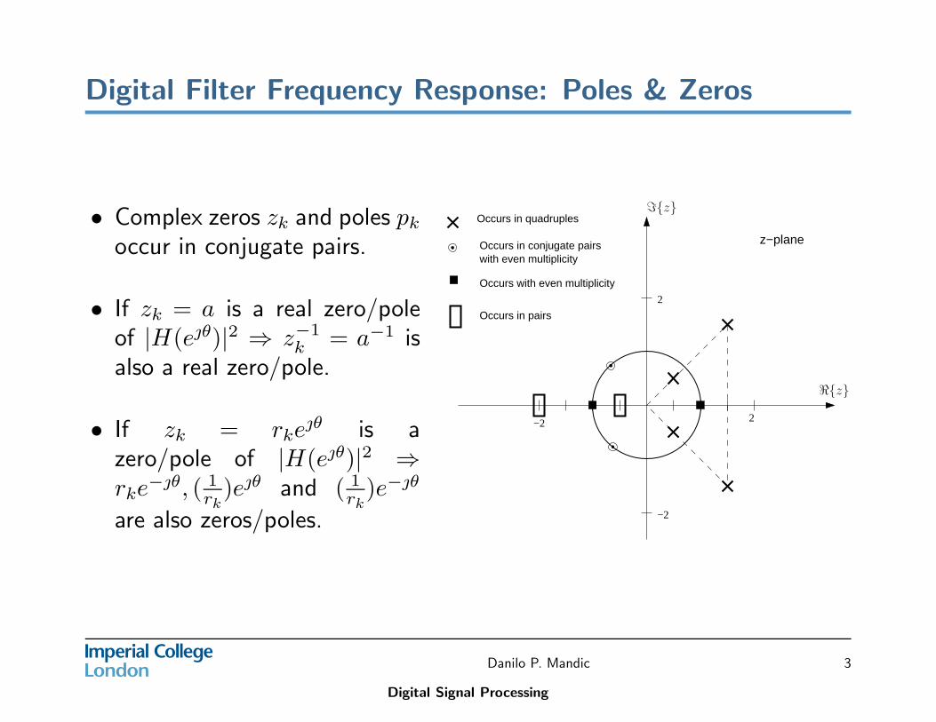
• Complex zeros zk and poles pk
occur in conjugate pairs.
• If zk = a is a real zero/poleof |H(eθ)|2 ⇒ z−1
k = a−1 isalso a real zero/pole.
• If zk = rkeθ is a
zero/pole of |H(eθ)|2 ⇒rke
−θ, ( 1rk
)eθ and ( 1rk
)e−θ
are also zeros/poles.
Occurs in pairs
Occurs with even multiplicity
with even multiplicityOccurs in conjugate pairs
Occurs in quadruples
z−plane
2
2
−2
−2
ℑ{z}
ℜ{z}
Danilo P. Mandic
Digital Signal Processing
3
Digital Filters: Transfer Functions
• The problem of finding the transfer function of a filter is the problem ofuniversal function approximation. This is usually solved by involvingsome basis functions (Fourier, Chebyshev, ...). In our case, the basisfunctions will be polynomials or rational functions in z (or z−1.
• Finite Impulse Response (FIR) filter: Digital filter characterised bytransfer functions in the form of a polynomial
H(z) = a0 + a1z−1 + · · · + zmz−M
• Infinite Impulse Response (IIR) filter: characterised by transferfunctions in the form of a rational function
H(z) =
MP
i=0aiz
−i
NP
j=0bjz−j
= A(z−1)B(z−1)
Danilo P. Mandic
Digital Signal Processing
4
Digital Filters: Transfer Functions Properties
• FIR filters are stable and causal.
• IIR filters are:
– Stable if all the poles of H(z) are within the unit circle– Causal if bL is the first non-zero coefficient in the denominator (i.e.
b0 = b1 = · · · = bL−1 = 0 and a0 = a1 = · · · = aL−1 = 0 .
• Causal filters are normally assumed, hence IIR filters are commonlywritten as:
H(z) =
MP
i=0aiz
−i
1+NP
j=1bjz−j
= A(z−1)B(z−1)
, b0 = 1
• We would ideally like to design filters with linear phase in thepassband - what about the phase in the stopband?
Danilo P. Mandic
Digital Signal Processing
5
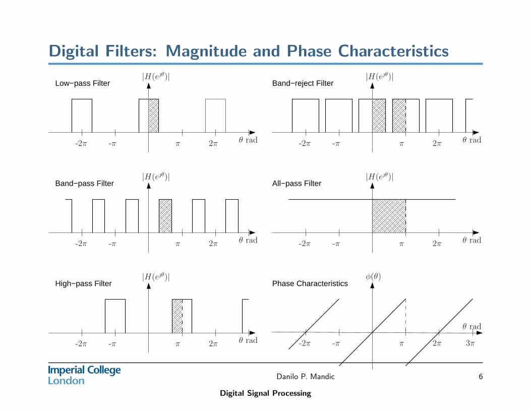
Digital Filters: Magnitude and Phase Characteristics
������������
������������
����������������
����������������
������������
������������
������������
������������
������������
������������
��������
��������
Phase Characteristics
Band−pass Filter All−pass Filter
Band−reject Filter
High−pass Filter
Low−pass Filter
θ rad2π
|H(eθ)|
π-π-2π
θ rad2π
|H(eθ)|
π-π-2π
-2π -π π
|H(eθ)|
2π θ rad
θ rad2π
|H(eθ)|
π-π-2π -2π -π π
|H(eθ)|
2π θ rad
-2π π 2π 3π-π
φ(θ)
θ rad
Danilo P. Mandic
Digital Signal Processing
6
Design of All-pass Digital Filters
• An all-pass filter is an IIR filter with a constant magnitude function forall digital frequency values.
• For a transfer function H(z) to represent an all-pass filter is that forevery pole pk = rke
jθ, there is a corresponding zero zk = 1rk
ejθ. Thepoles and zeros will occur in conjugate pairs if θk 6= 0 or π.
• A digital filter H(z) obtained by cascade connection of multiple all-passfilters H1(z),H2(z) · · ·HN(z) sections is itself an all-pass filter, and canbe represented by
H(z) = H1(z)H2(z) · · ·HN(z)
◦ So why do we need all-pass filters? They are phase-selective (asopposed to frequency selective) and are extremely useful in thedesign of DSP systems.
Danilo P. Mandic
Digital Signal Processing
7

First order All-pass Digital Filter
• A typical first-order section of an all-pass digital filter has a transferfunction
H1(z) =z−1 − a
1 − az−1(1)
where a is real and to be stable, we must have |a| < 1.
a
Unit Circle
Re[z]
Im[z]
1/a
Figure 1: Pole-zero pattern of first order all-pass digital filter.
Danilo P. Mandic
Digital Signal Processing
8
First- and Second-Order All-pass Digital Filter
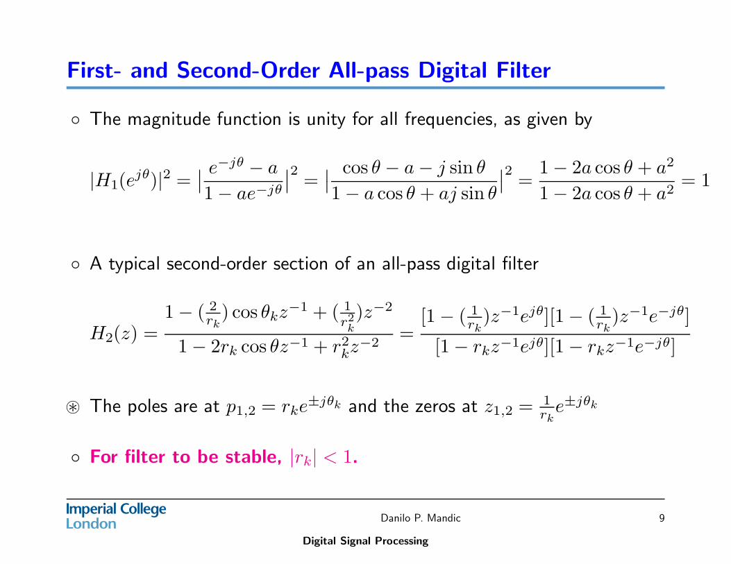
◦ The magnitude function is unity for all frequencies, as given by
|H1(ejθ)|2 =
∣
∣
e−jθ − a
1 − ae−jθ
∣
∣
2=
∣
∣
cos θ − a − j sin θ
1 − a cos θ + aj sin θ
∣
∣
2=
1 − 2a cos θ + a2
1 − 2a cos θ + a2= 1
◦ A typical second-order section of an all-pass digital filter
H2(z) =1 − ( 2
rk) cos θkz
−1 + ( 1r2k)z−2
1 − 2rk cos θz−1 + r2kz
−2=
[1 − ( 1rk
)z−1ejθ][1 − ( 1rk
)z−1e−jθ]
[1 − rkz−1ejθ][1 − rkz−1e−jθ]
⊛ The poles are at p1,2 = rke±jθk and the zeros at z1,2 = 1
rke±jθk
◦ For filter to be stable, |rk| < 1.
Danilo P. Mandic
Digital Signal Processing
9
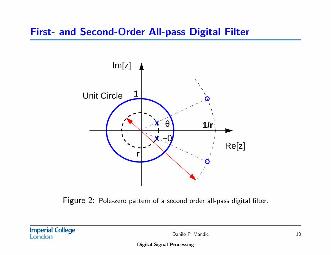
First- and Second-Order All-pass Digital Filter
X −θ
θ
r
1
Im[z]
Unit Circle
Re[z]
1/rX
Figure 2: Pole-zero pattern of a second order all-pass digital filter.
Danilo P. Mandic
Digital Signal Processing
10
First order All-pass Digital Filter
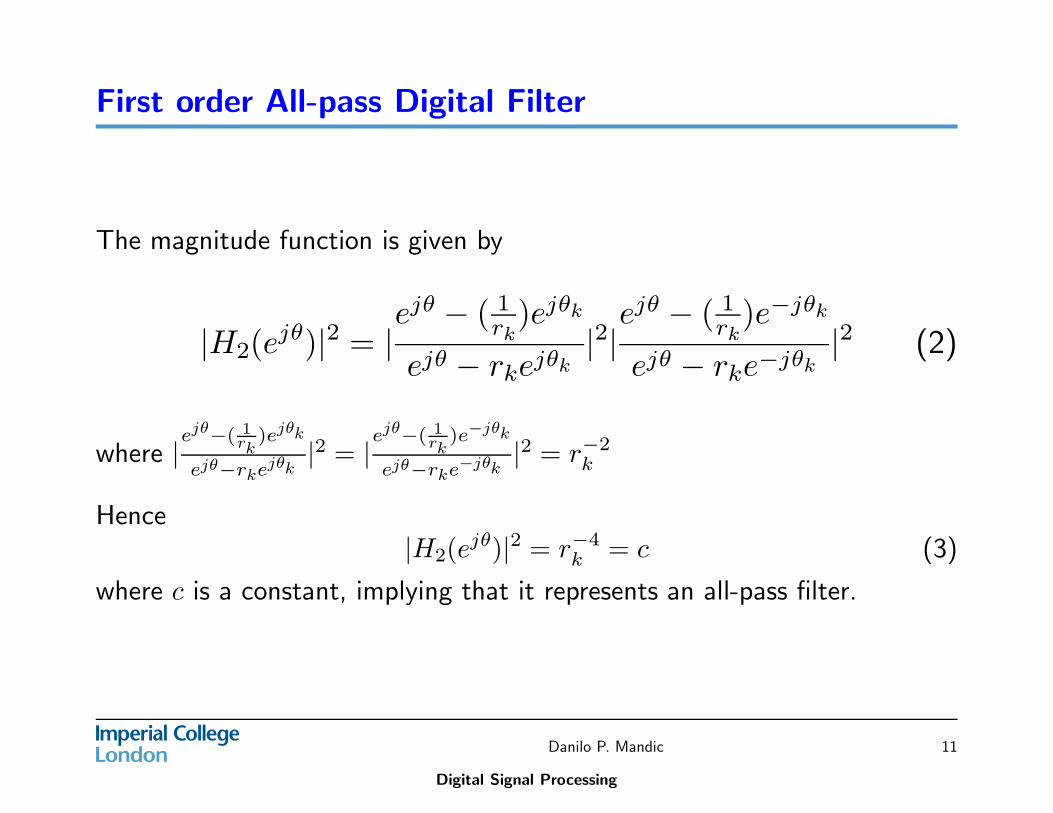
The magnitude function is given by
|H2(ejθ)|2 = |
ejθ − ( 1rk
)ejθk
ejθ − rkejθk|2|
ejθ − ( 1rk
)e−jθk
ejθ − rke−jθk|2 (2)
where |ejθ−( 1
rk)ejθk
ejθ−rkejθk|2 = |
ejθ−( 1rk
)e−jθk
ejθ−rke−jθk|2 = r−2
k
Hence|H2(e
jθ)|2 = r−4k = c (3)
where c is a constant, implying that it represents an all-pass filter.
Danilo P. Mandic
Digital Signal Processing
11

Design of FIR Digital Filter
The transfer function of FIR digital filter is in the form of
H(z) =
N−1X
n=0
h(n)z−n
(4)
where the impulse response is of length N .
The filter will have linear phase response if the FIR digital filter satisfies
h(n) = h(N − 1 − n) (5)
Danilo P. Mandic
Digital Signal Processing
12
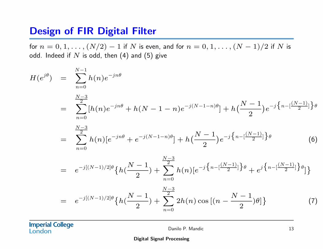
Design of FIR Digital Filter
for n = 0, 1, . . . , (N/2) − 1 if N is even, and for n = 0, 1, . . . , (N − 1)/2 if N is
odd. Indeed if N is odd, then (4) and (5) give
H(ejθ
) =N−1X
n=0
h(n)e−jnθ
=
N−32
X
n=0
[h(n)e−jnθ + h(N − 1 − n)e−j(N−1−n)θ] + h`N − 1
2
´
e−j˘
n−[(N−1)
2 ]¯
θ
=
N−32
X
n=0
h(n)[e−jnθ + e−j(N−1−n)θ] + h`N − 1
2
´
e−j˘
n−[(N−1)
2 ]¯
θ(6)
= e−j[(N−1)/2]θ˘
h(N − 1
2) +
N−32
X
n=0
h(n)[e−j
˘
n−[(N−1)
2 ]¯
θ+ e
j˘
n−[(N−1)
2 ]¯
θ]¯
= e−j[(N−1)/2]θ˘
h(N − 1
2) +
N−32
X
n=0
2h(n) cos [(n −N − 1
2)θ]
¯
(7)
Danilo P. Mandic
Digital Signal Processing
13
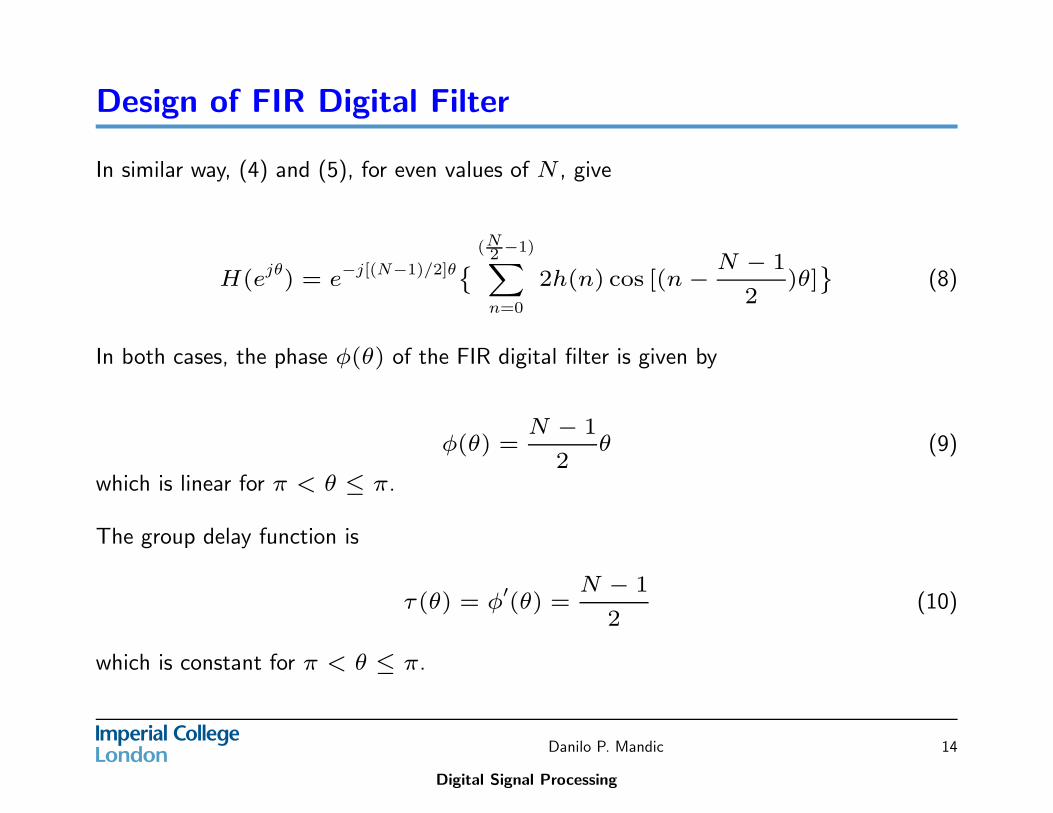
Design of FIR Digital Filter
In similar way, (4) and (5), for even values of N , give
H(ejθ) = e−j[(N−1)/2]θ˘
(N2 −1)X
n=0
2h(n) cos [(n −N − 1
2)θ]
¯
(8)
In both cases, the phase φ(θ) of the FIR digital filter is given by
φ(θ) =N − 1
2θ (9)
which is linear for π < θ ≤ π.
The group delay function is
τ(θ) = φ′(θ) =
N − 1
2(10)
which is constant for π < θ ≤ π.
Danilo P. Mandic
Digital Signal Processing
14
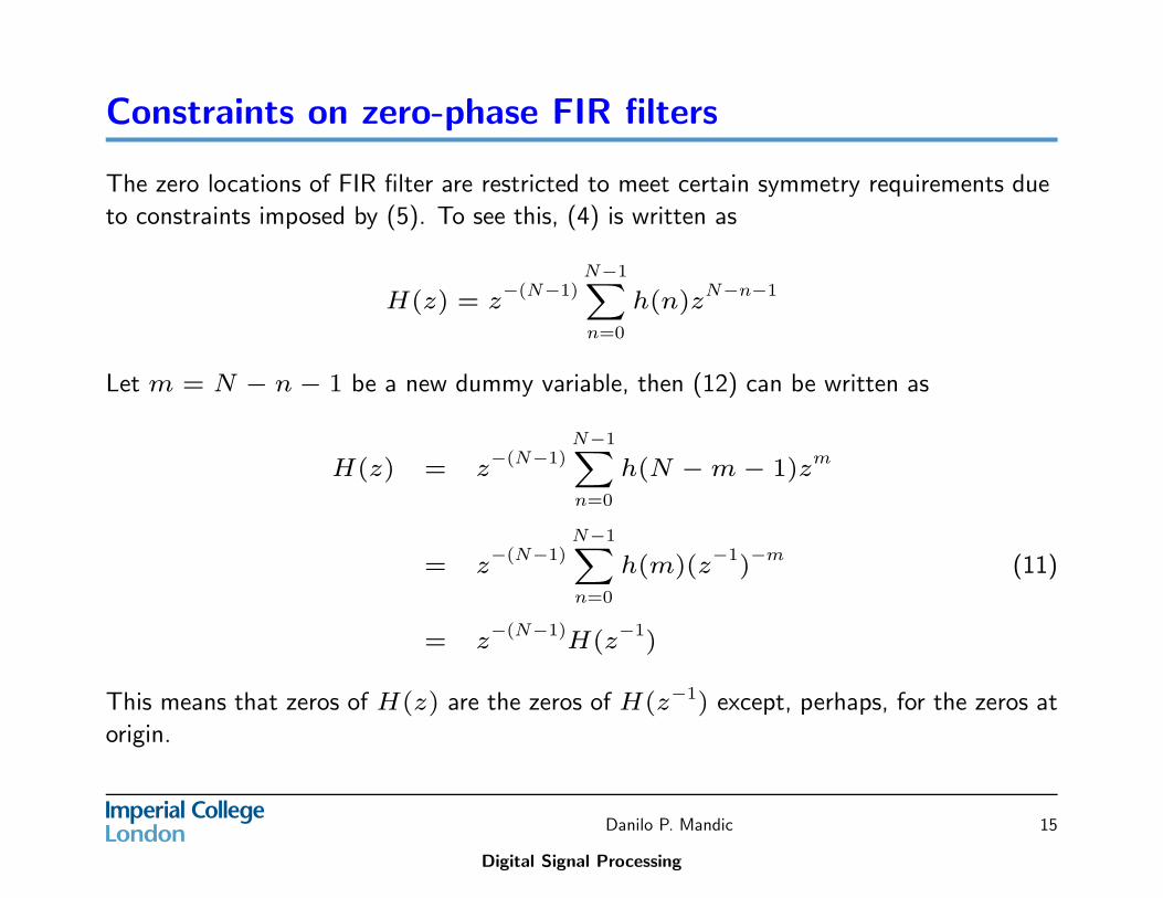
Constraints on zero-phase FIR filters
The zero locations of FIR filter are restricted to meet certain symmetry requirements due
to constraints imposed by (5). To see this, (4) is written as
H(z) = z−(N−1)
N−1X
n=0
h(n)zN−n−1
Let m = N − n − 1 be a new dummy variable, then (12) can be written as
H(z) = z−(N−1)N−1X
n=0
h(N − m − 1)zm
= z−(N−1)
N−1X
n=0
h(m)(z−1
)−m
(11)
= z−(N−1)
H(z−1
)
This means that zeros of H(z) are the zeros of H(z−1) except, perhaps, for the zeros at
origin.
Danilo P. Mandic
Digital Signal Processing
15
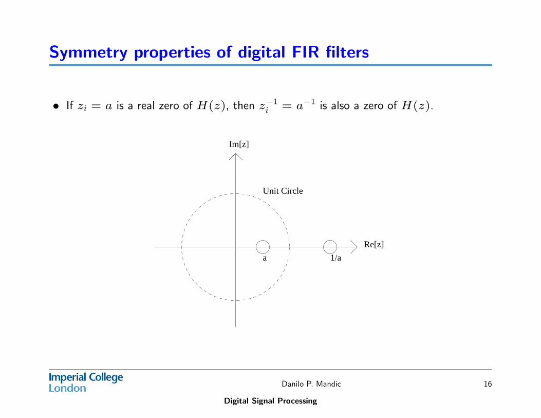
Symmetry properties of digital FIR filters
• If zi = a is a real zero of H(z), then z−1i = a−1 is also a zero of H(z).
Unit Circle
a 1/a
Im[z]
Re[z]
Danilo P. Mandic
Digital Signal Processing
16

Symmetry properties of digital FIR filters
• If zi = ejθi is a zero of H(z), where θi 6= 0 and θi 6= π, then z−1i = zi = e−jθi is
also a zero of H(z).
Unit Circle
Im[z]
Re[z]
Danilo P. Mandic
Digital Signal Processing
17
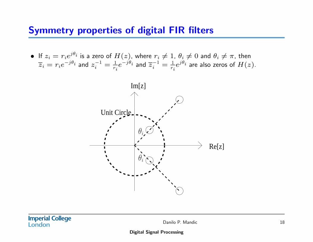
Symmetry properties of digital FIR filters
• If zi = riejθi is a zero of H(z), where ri 6= 1, θi 6= 0 and θi 6= π, then
zi = rie−jθi and z−1
i = 1ri
e−jθi and z−1i = 1
riejθi are also zeros of H(z).
Re[z]
Unit Circle
Im[z]
θi
θi
Danilo P. Mandic
Digital Signal Processing
18
Frequency sampling method
An FIR filter has equivalent DFT representation, given by
eH(k) =
N−1X
n=0
h(n)e[−
j2πnkN
](12)
where eH(k) is actually the uniformly spaced N-point sample sequence of the
frequency response of the digital filter. As a consequence, the impulse response
sequence h(n) and transfer function H(z) are given by
h(n) =1
N
N−1X
k=0
eH(k)e[j2πnk
N]
(13)
and
H(z) =1
N
N−1X
k=0
eH(k)1 − z−N
1 − z−1e[j2πk
N]
(14)
where equation (14) is the key to the design of FIR digital filter.
Danilo P. Mandic
Digital Signal Processing
19
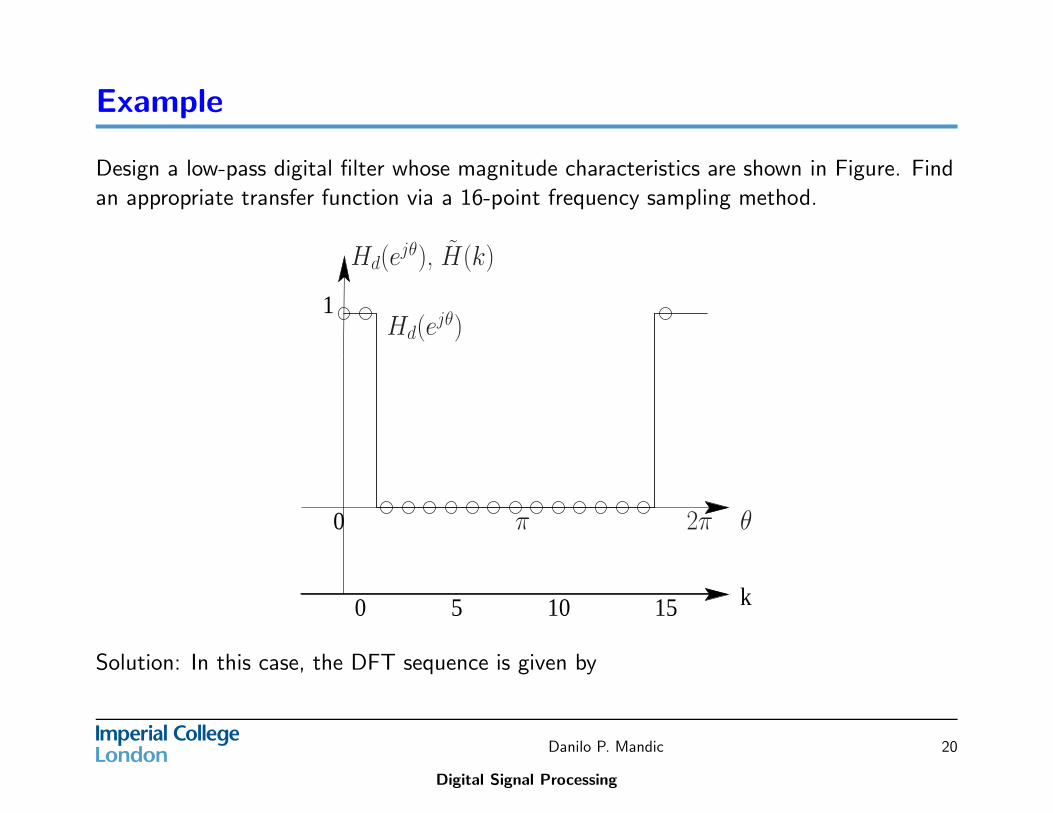
Example
Design a low-pass digital filter whose magnitude characteristics are shown in Figure. Find
an appropriate transfer function via a 16-point frequency sampling method.
k151050
0
1
Hd(ejθ), H̃(k)
2π θπ
Hd(ejθ)
Solution: In this case, the DFT sequence is given by
Danilo P. Mandic
Digital Signal Processing
20
Example
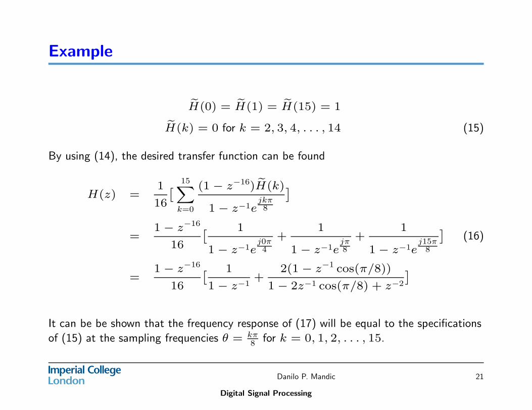
eH(0) = eH(1) = eH(15) = 1
eH(k) = 0 for k = 2, 3, 4, . . . , 14 (15)
By using (14), the desired transfer function can be found
H(z) =1
16
ˆ
15X
k=0
(1 − z−16) eH(k)
1 − z−1ejkπ8
˜
=1 − z−16
16
ˆ 1
1 − z−1ej0π4
+1
1 − z−1ejπ8
+1
1 − z−1ej15π
8
˜
(16)
=1 − z−16
16
ˆ 1
1 − z−1+
2(1 − z−1 cos(π/8))
1 − 2z−1 cos(π/8) + z−2
˜
It can be be shown that the frequency response of (17) will be equal to the specifications
of (15) at the sampling frequencies θ = kπ8 for k = 0, 1, 2, . . . , 15.
Danilo P. Mandic
Digital Signal Processing
21
The Windowing Method
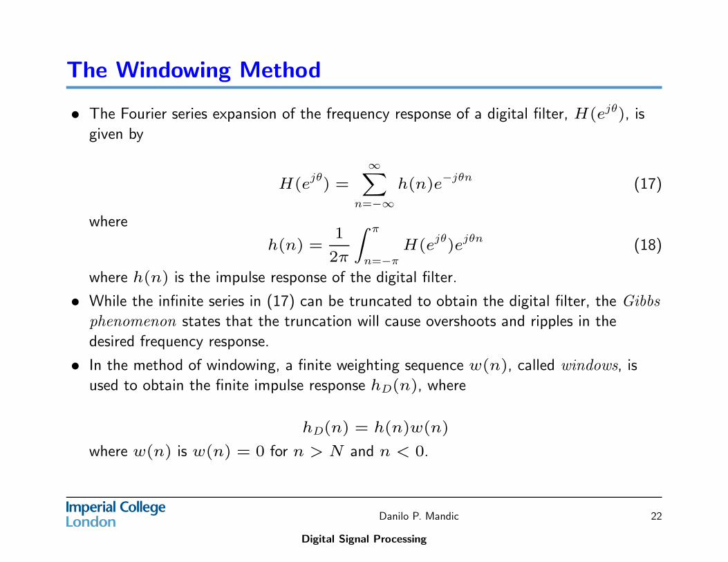
• The Fourier series expansion of the frequency response of a digital filter, H(ejθ), is
given by
H(ejθ
) =
∞X
n=−∞
h(n)e−jθn
(17)
where
h(n) =1
2π
Z π
n=−π
H(ejθ
)ejθn
(18)
where h(n) is the impulse response of the digital filter.
• While the infinite series in (17) can be truncated to obtain the digital filter, the Gibbs
phenomenon states that the truncation will cause overshoots and ripples in the
desired frequency response.
• In the method of windowing, a finite weighting sequence w(n), called windows, is
used to obtain the finite impulse response hD(n), where
hD(n) = h(n)w(n)
where w(n) is w(n) = 0 for n > N and n < 0.
Danilo P. Mandic
Digital Signal Processing
22
The Windowing Method
• Given the desired frequency response H(ejθ), which may be obtained bythe frequency sampling method.
• Find the associated impulse response sequence h(n) from 17 or byinverse z-transform of H(z), where H(z) is obtained from H(ejθ) byreplacing ejθ with z.
• Employ an appropriate window function w(n) to modify the sequenceh(n) to obtain the FIR digital filter’s impulse response sequencehD(n) = h(n)w(n).
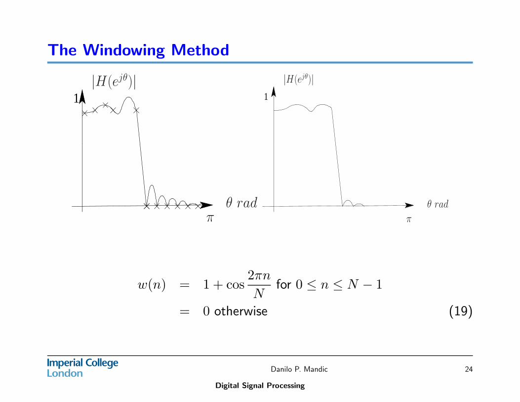
The windowing method has the effect of smoothing out the ripples andovershoots in the original frequency response as shown in the figure for asimple window function
Danilo P. Mandic
Digital Signal Processing
23
The Windowing Method
1|H(ejθ)|
πθ rad
1
π
|H(ejθ)|
θ rad
w(n) = 1 + cos2πn
Nfor 0 ≤ n ≤ N − 1
= 0 otherwise (19)
Danilo P. Mandic
Digital Signal Processing
24
The Windowing Method: Some common window
functions
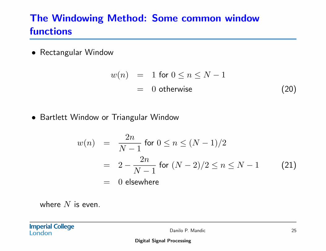
• Rectangular Window
w(n) = 1 for 0 ≤ n ≤ N − 1
= 0 otherwise (20)
• Bartlett Window or Triangular Window
w(n) =2n
N − 1for 0 ≤ n ≤ (N − 1)/2
= 2 −2n
N − 1for (N − 2)/2 ≤ n ≤ N − 1 (21)
= 0 elsewhere
where N is even.
Danilo P. Mandic
Digital Signal Processing
25
The Windowing Method: Some common window
functions
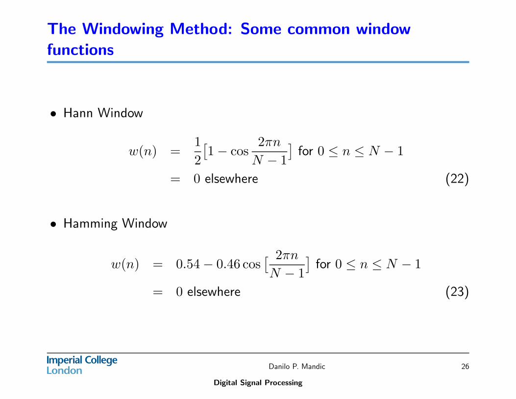
• Hann Window
w(n) =1
2
[
1 − cos2πn
N − 1
]
for 0 ≤ n ≤ N − 1
= 0 elsewhere (22)
• Hamming Window
w(n) = 0.54 − 0.46 cos[ 2πn
N − 1
]
for 0 ≤ n ≤ N − 1
= 0 elsewhere (23)
Danilo P. Mandic
Digital Signal Processing
26
The Windowing Method: Some common window
functions
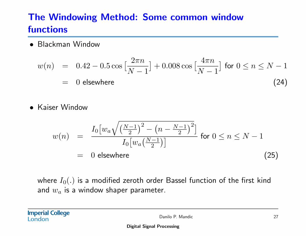
• Blackman Window
w(n) = 0.42 − 0.5 cos[ 2πn
N − 1
]
+ 0.008 cos[ 4πn
N − 1
]
for 0 ≤ n ≤ N − 1
= 0 elsewhere (24)
• Kaiser Window
w(n) =I0
[
wa
√
(
N−12
)2−
(
n − N−12
)2]
I0
[
wa
(
N−12
)] for 0 ≤ n ≤ N − 1
= 0 elsewhere (25)
where I0(.) is a modified zeroth order Bassel function of the first kindand wa is a window shaper parameter.
Danilo P. Mandic
Digital Signal Processing
27
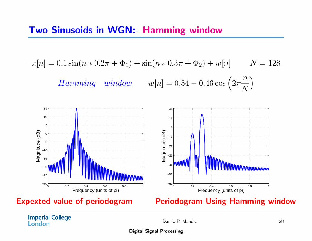
Two Sinusoids in WGN:- Hamming window
x[n] = 0.1 sin(n ∗ 0.2π + Φ1) + sin(n ∗ 0.3π + Φ2) + w[n] N = 128
Hamming window w[n] = 0.54 − 0.46 cos(
2πn
N
)
0 0.2 0.4 0.6 0.8 1−30
−25
−20
−15
−10
−5
0
5
10
15
Frequency (units of pi)
Mag
nitu
de (
dB)
0 0.2 0.4 0.6 0.8 1−60
−50
−40
−30
−20
−10
0
10
20
Frequency (units of pi)
Mag
nitu
de (
dB)
Expexted value of periodogram Periodogram Using Hamming window
Danilo P. Mandic
Digital Signal Processing
28
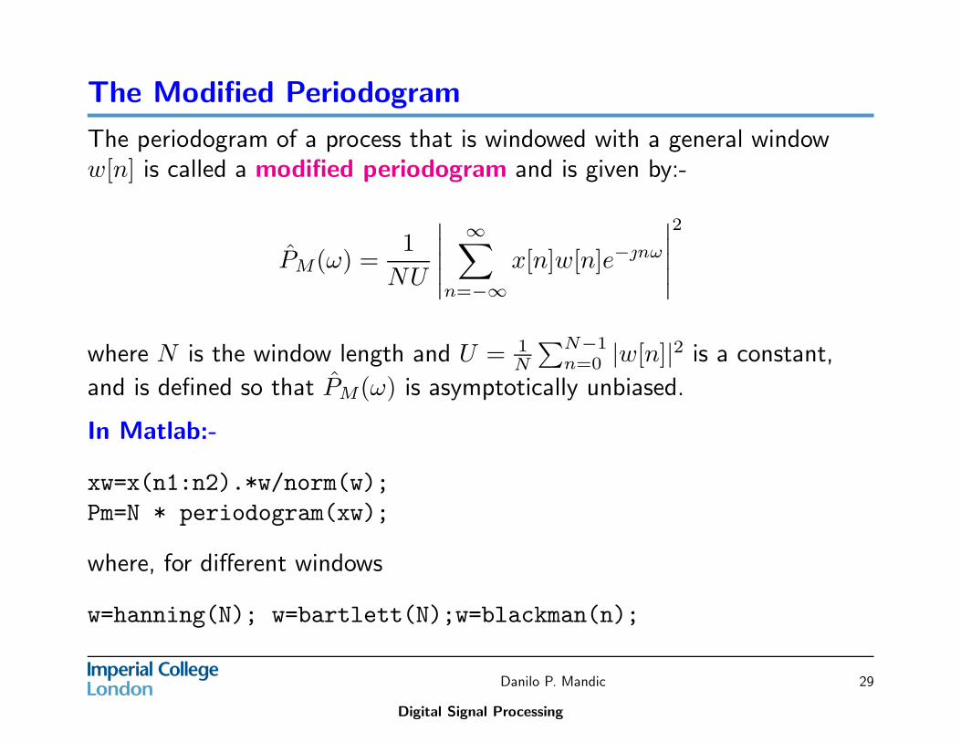
The Modified Periodogram
The periodogram of a process that is windowed with a general windoww[n] is called a modified periodogram and is given by:-
P̂M(ω) =1
NU
∣
∣
∣
∣
∣
∞∑
n=−∞
x[n]w[n]e−nω
∣
∣
∣
∣
∣
2
where N is the window length and U = 1N
∑N−1n=0 |w[n]|2 is a constant,
and is defined so that P̂M(ω) is asymptotically unbiased.
In Matlab:-
xw=x(n1:n2).*w/norm(w);
Pm=N * periodogram(xw);
where, for different windows
w=hanning(N); w=bartlett(N);w=blackman(n);
Danilo P. Mandic
Digital Signal Processing
29
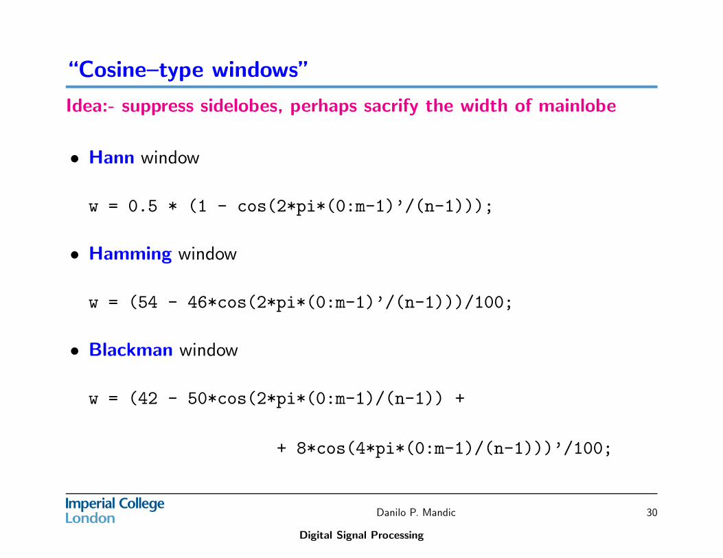
“Cosine–type windows”
Idea:- suppress sidelobes, perhaps sacrify the width of mainlobe
• Hann window
w = 0.5 * (1 - cos(2*pi*(0:m-1)’/(n-1)));
• Hamming window
w = (54 - 46*cos(2*pi*(0:m-1)’/(n-1)))/100;
• Blackman window
w = (42 - 50*cos(2*pi*(0:m-1)/(n-1)) +
+ 8*cos(4*pi*(0:m-1)/(n-1)))’/100;
Danilo P. Mandic
Digital Signal Processing
30
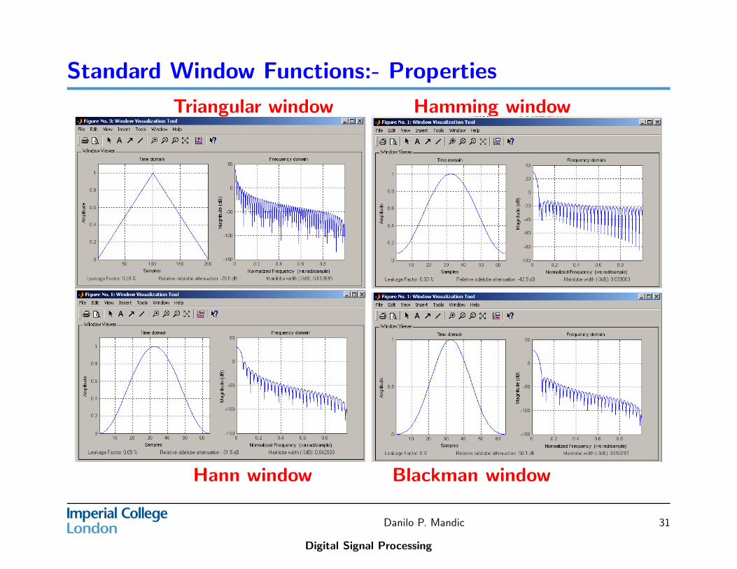
Standard Window Functions:- Properties
Triangular window Hamming window
Hann window Blackman window
Danilo P. Mandic
Digital Signal Processing
31
Some Comments on FIR digital Filter
• Unlike IIR filters, FIR filters can be designed to have linear phasecharacteristics.
• FIR filters are always stable.
• FIR filters are, however, computationally more expensive than IIR filtersand hence are called for to perform tasks not possible/or not practicalby IIR filters such as linear phase, and multirate filters.
Danilo P. Mandic
Digital Signal Processing
32