Development of HALNA DPSSL for...
22
Development of HALNA DPSSL for IFE Yasukazu Izawa Institute of Laser Engineering, Osaka University 5th US-Japan Workshop on Laser IFE March 21-22, 2005 General Atomics 1
Transcript of Development of HALNA DPSSL for...
Development of HALNA DPSSL for IFE
Yasukazu IzawaInstitute of Laser Engineering, Osaka University
5th US-Japan Workshop on Laser IFE March 21-22, 2005General Atomics
1
Contributors
Tadashi Kanabe*, Masanobu Yamanaka**, Ryo Yasuhara, Junji Kawanaka, Noriaki Miyanaga, Takayoshi Norimatsu,
and Masahiro Nakatsuka Institute of Laser Engineering, Osaka University
*Fukui University** Graduate School, University of Advanced Photonics
Osamu Matsumoto, Toshiyuki Kawashima, Takashi Sekine,Takashi Kurita, Tadashi Ikegawa, Masahiro Miyamoto,
Takeshi Kanzaki and Hirofumi KanHamamatsu Photonics K.K.
Hiroyuki FurukawaInstitute for Laser Technology
Institute for Laser Technology
2
ILE OSAKA
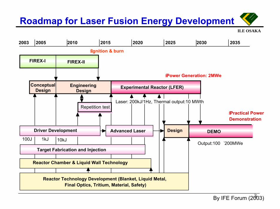
Roadmap for Laser Fusion Energy Development
3
�£Ignition & burn
Repetition test
FIREX-I FIREX-II
2005 2010 2015 2020 2025 2030 2035
100J 1kJ
�£Power Generation: 2MWe
�£Practical Power Demonstration
Advanced Laser
Reactor Technology Development (Blanket, Liquid Metal, Final Optics, Tritium, Material, Safety)
Output:100� 2̀00MWe
DEMODesign
2003
Experimental Reactor (LFER)Engineering Design
Laser: 200kJ/1Hz, Thermal output:10 MWth
Target Fabrication and Injection
Reactor Chamber & Liquid Wall Technology
10kJ
Driver Development
Conceptual Design
By IFE Forum (2003)
4
ILE OSAKA
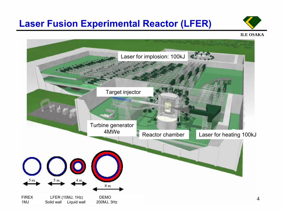
Laser for implosion: 100kJ
Reactor chamber Laser for heating 100kJ
Target injector
Turbine generator4MWe
FIREX LFER (10MJ, 1Hz) DEMO1MJ Solid wall Liquid wall 200MJ, 3Hz
Laser Fusion Experimental Reactor (LFER)
Two approaches for IFE driver development
� HALNA (High Average-power Laser for Nuclear-fusion Application) conceptual architecture consists of water-cooling, Nd:glass medium and zig-zag slab geometry and multi-pass amplifier.
� Current goals of the HALNA are 100 J pulse energy, 10 Hz operation and beam quality less than 5 times of diffraction limit (TDL) with 10% overall efficiency.
� New approach is to use cooled Yb: YAG ceramic slab.(20 x 20 x 5 cm for 1kJ, T = 150 ~ 225 K)(To be presented by J. Kawanaka)
5
6
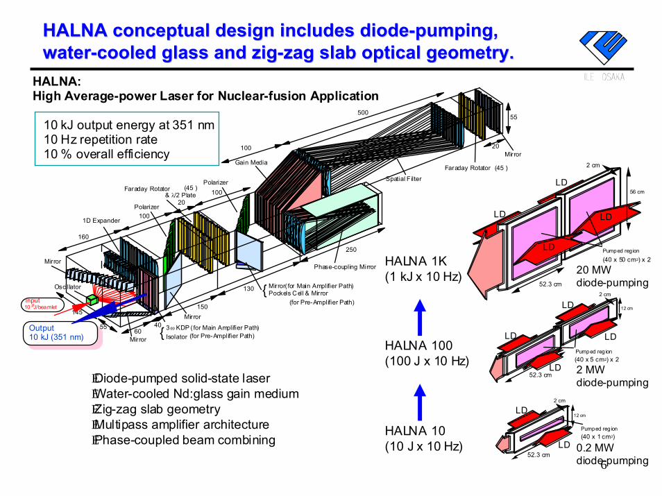
HALNA: High Average-power Laser for Nuclear-fusion Application
Output10 kJ (351 nm)
Oscillator
Mirror
1D Expander
Polarizer
Faraday Rotator Polarizer
Gain Media
Spatial F ilter
160
100
20100
100
500
145
55
Mirror60
40
150
ω3 KDP ( for Main Amplifier Path)Isolator {
Mirror
130 Mirror( for Main Amplifier Path) Pockels Cell & Mirror
{
250
Phase-coupling Mirror
20
55
(for Pre-Amplifier Path)Inputµ10 J/beamlet
& λ/2 Plate �›(45 )
�›(45 )
(for Pre-Amplifier Path)
Faraday Rotator
Mirror
�EDiode-pumped solid-state laser �EWater-cooled Nd:glass gain medium �EZig-zag slab geometry �EMultipass amplifier architecture �EPhase-coupled beam combining
10 kJ output energy at 351 nm 10 Hz repetition rate 10 % overall efficiency
LD
LD
(40 x 5 cm2) x 2Pumped reg ion
12 cm
52.3 cmLD
LD
2 cm
2 cm
52.3 cm
12 cm
LD
LD
(40 x 1 cm2) Pumped regionHALNA 10
(10 J x 10 Hz)
HALNA 100 (100 J x 10 Hz)
HALNA 1K (1 kJ x 10 Hz)
(40 x 50 cm2) x 2Pumped reg ion
LD
LD
2 cm
56 cm
LD
52.3 cm
LD
0.2 MW diode-pumping
2 MW diode-pumping
20 MW diode-pumping
HALNA conceptual design includes diodeHALNA conceptual design includes diode--pumping, pumping, waterwater--cooled glass andcooled glass and zigzig--zag zag slab optical geometry.slab optical geometry.
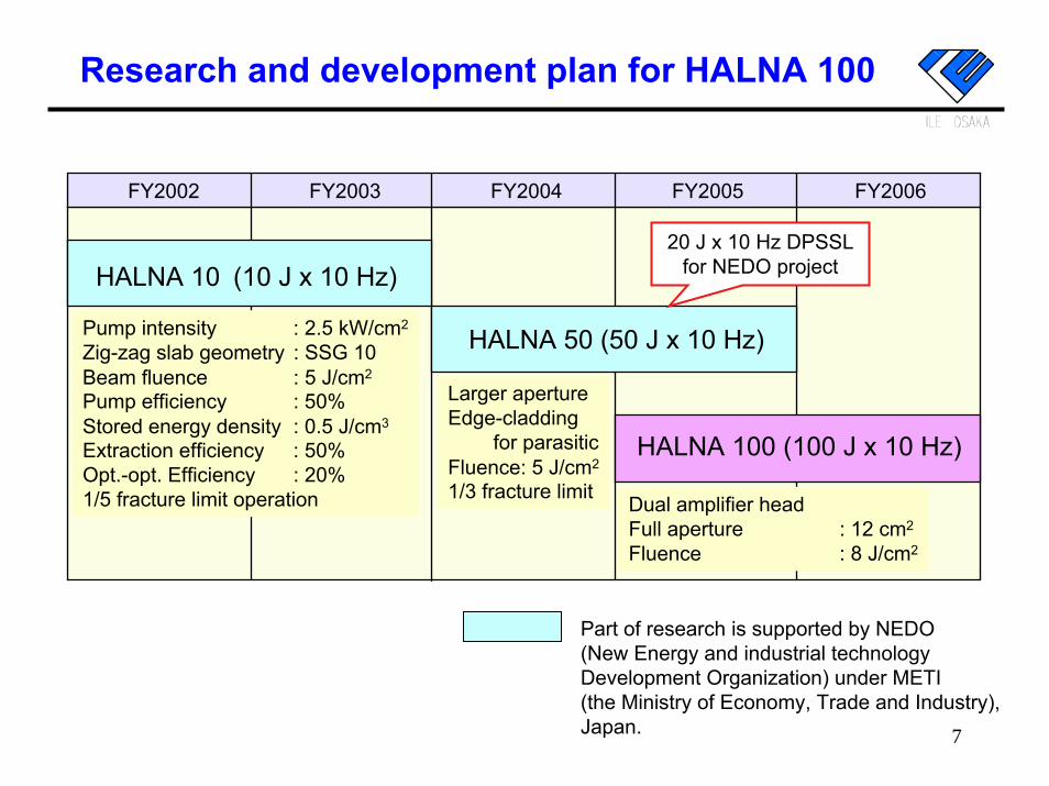
Research and development plan for HALNA 100
FY2002 FY2003 FY2004 FY2005 FY2006
HALNA 10 (10 J x 10 Hz)
HALNA 50 (50 J x 10 Hz)
HALNA 100 (100 J x 10 Hz)
Pump intensity : 2.5 kW/cm2
Zig-zag slab geometry : SSG 10Beam fluence : 5 J/cm2
Pump efficiency : 50%Stored energy density : 0.5 J/cm3
Extraction efficiency : 50%Opt.-opt. Efficiency : 20%1/5 fracture limit operation Dual amplifier head
Full aperture : 12 cm2
Fluence : 8 J/cm2
Larger apertureEdge-cladding
for parasiticFluence: 5 J/cm2
1/3 fracture limit
20 J x 10 Hz DPSSLfor NEDO project
7
Part of research is supported by NEDO(New Energy and industrial technology Development Organization) under METI (the Ministry of Economy, Trade and Industry),Japan.
ILE OSAKA
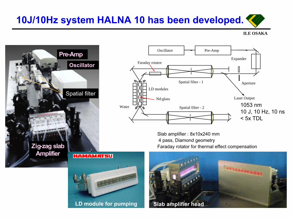
10J/10Hz system HALNA 10 has been developed.
8
1053 nm10 J, 10 Hz, 10 ns< 5x TDL
Water
Oscillator Pre-Amp
Spatial filter - 1
Spatial filter - 2
Laser Output
LD modules
Nd:glass
Faraday rotatorExpander
Aperture
Slab amplifier headLD module for pumping
Slab amplifier : 8x10x240 mm 4 pass, Diamond geometry Faraday rotator for thermal effect compensation
Pre-AmpOscillator
Zig-zag slabAmplifier
Spatial filter
PHOTON IS OUR BUSINESS
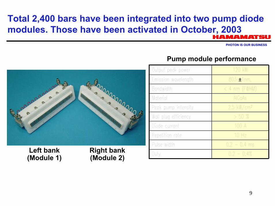
Total 2,400 bars have been integrated into two pump diode modules. Those have been activated in October, 2003
9
Left bank(Module 1)
Right bank(Module 2)
±
Pump module performance
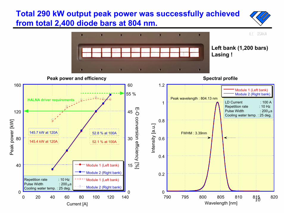
Total 290 kW output peak power was successfully achieved from total 2,400 diode bars at 804 nm.
Left bank (1,200 bars)Lasing !
100
40
80
120
160
0
15
30
45
60
0 20 40 60 80 100 120 140
Peak power and efficiency
Module 1 (Left bank)
Module 2 (Right bank)
Module 1 (Left bank)
Module 2 (Right bank)
Current [A]
HALNA driver requirements
52.1 % at 100A
52.8 % at 100A
145.4 kW at 120A
145.7 kW at 120A
Repetition rate : 10 HzPulse Width : 200 µsCooling water temp. : 25 deg.
55 %
E-O
conversion efficiency [%]
Pea
k po
wer
[kW
]
0
0.2
0.4
0.6
0.8
1
1.2
790 795 800 805 810 815 820
Spectral profile
Module 1 (Left bank)Module 2 (Right bank)
Wavelength [nm]
LD Current : 100 ARepetition rate : 10 HzPulse Width : 200 µsCooling water temp. : 25 deg.
FWHM : 3.39nm
Peak wavelength : 804.13 nm
Inte
nsity
[a.u
.]
ILE OSAKAILE OSAKA
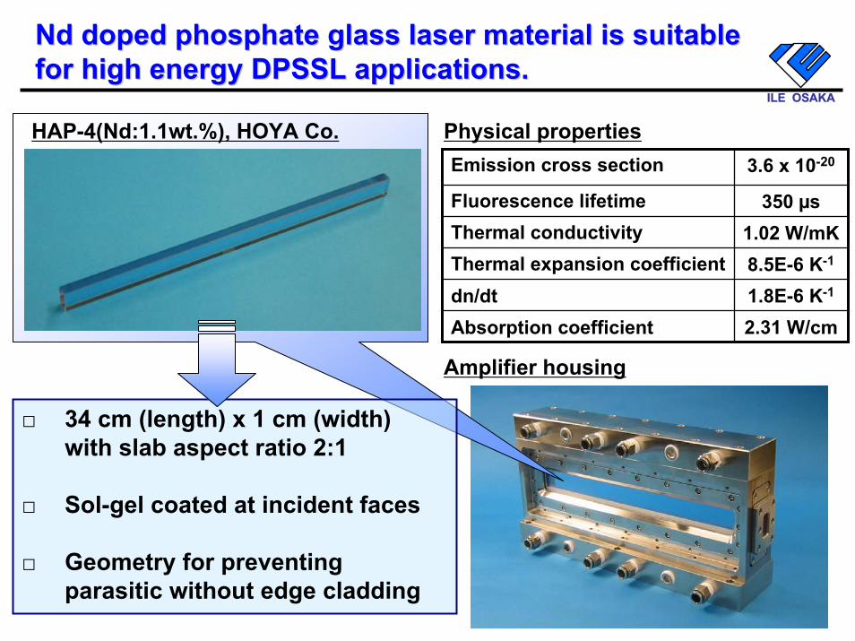
Nd Nd doped phosphate glass laser material is suitable doped phosphate glass laser material is suitable for high energy DPSSL applications.for high energy DPSSL applications.
11
Emission cross section 3.6 x 10⁻²⁰
Fluorescence lifetime 350 µsThermal conductivity 1.02 W/mKThermal expansion coefficient 8.5E-6 K-1
dn/dt 1.8E-6 K-1
Absorption coefficient 2.31 W/cm
Physical propertiesHAP-4(Nd:1.1wt.%), HOYA Co.
Amplifier housing
34 cm (length) x 1 cm (width) with slab aspect ratio 2:1
Sol-gel coated at incident faces
Geometry for preventing parasitic without edge cladding
□
□
□
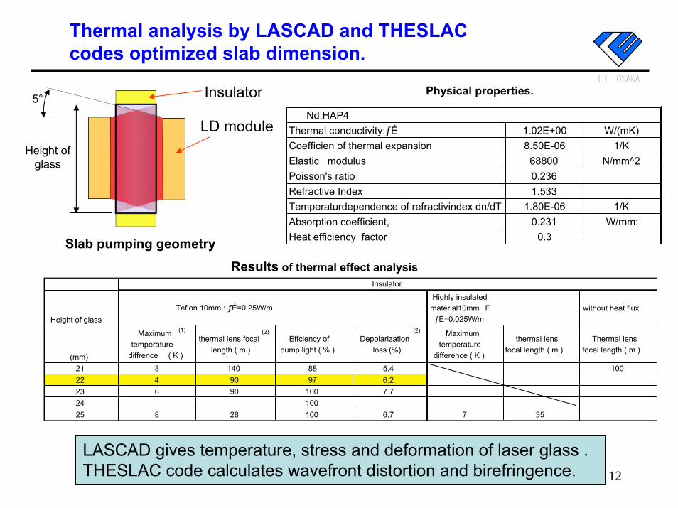
Thermal analysis by LASCAD and THESLAC codes optimized slab dimension.
Physical properties.
Nd:HAP4Thermal conductivity:ă 1.02E+00 W/(mK)Coefficien of thermal expansion 8.50E-06 1/KElastic modulus 68800 N/mm^2Poisson's ratio 0.236Refractive Index 1.533Temperaturdependence of refractivindex dn/dT 1.80E-06 1/KAbsorption coefficient, 0.231 W/mm:Heat efficiency factor 0.3
LD module
Insulator
Height of glass
5°
Slab pumping geometry
Results of thermal effect analysisInsulator
Height of glassTeflon 10mm : ă=0.25W/m
Highly insulatedmaterial10mm�F
ă=0.025W/mwithout heat flux
(mm)
Maximumtemperature
diffrence ( K )
thermal lens focallength ( m )
Effciency ofpump light ( % )
Depolarizationloss (%)
Maximumtemperature
difference ( K )
thermal lensfocal length ( m )
Thermal lensfocal length ( m )
21 3 140 88 5.4 -10022 4 90 97 6.223 6 90 100 7.724 10025 8 28 100 6.7 7 35
(1) (2) (2)
LASCAD gives temperature, stress and deformation of laser glass .THESLAC code calculates wavefront distortion and birefringence. 12
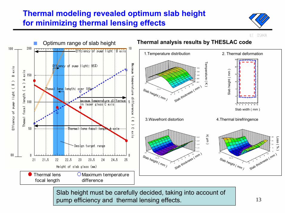
Thermal modeling revealed optimum slab height for minimizing thermal lensing effects
13
1.Temperature distribution
4.Thermal birefringence3.Wavefront distortion
Tempera tu re ( K
)
L os s ( % )
Slab height ( mm ) Slab thickness ( mm )
λ ( µ m )
-5
0
5
10
15
20
25
-2 0 2 4 6 8 10 12
2. Thermal deformation
Sla
b he
ight
( m
m )
Slab width ( mm )
Slab height ( mm ) Slab thickness ( mm )
Slab height ( mm )Slab thickness ( m
m )
Thermal analysis results by THESLAC code■ Optimum range of slab height
Slab height must be carefully decided, taking into account of pump efficiency and thermal lensing effects.
Thermal lensfocal length
Maximum temperature difference
Thermal lensfocal length
Maximum temperature difference
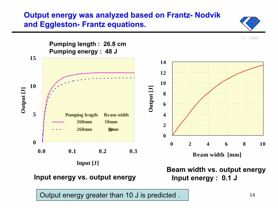
Output energy was analyzed based on Frantz- Nodvik and Eggleston- Frantz equations.
0
5
10
15
0.0 0.1 0.2 0.3
Input [J]
Out
put [
J]
Pumping length Beam width 268mm 10mm 268mm �@8mm
14Output energy greater than 10 J is predicted .
Input energy vs. output energyBeam width vs. output energy
Input energy : 0.1 J
0
2
4
6
8
10
12
14
0 2 4 6 8 10
Beam width [mm]O
utpu
t [J]
Pumping length : 26.8 cmPumping energy : 48 J
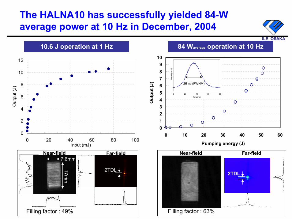
The HALNA10 has successfully yielded 84-W average power at 10 Hz in December, 2004
0123456789
10
0 10 20 30 40 50 60
Pumping energy (J)
Out
put (
J)
15
0
2
4
6
8
10
12
0 20 40 60 80 100Input (mJ)
Out
put (
J)
10.6 J operation at 1 Hz 84 Waverage operation at 10 Hz
Filling factor : 49%
2TDL
Near-field Far-field7.6mm
17mm
Near-field
Filling factor : 63%
0 20 40 60 80Time (ns)
Inte
nsity
(a.u
.)
26 ns (FWHM)
Far-field
ILE OSAKAILE OSAKA
2TDL
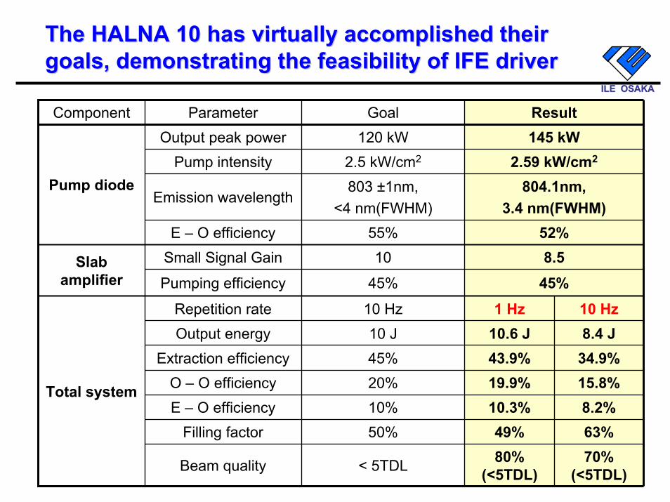
The HALNA 10 has virtually accomplished their The HALNA 10 has virtually accomplished their goals, demonstrating the feasibility of IFE drivergoals, demonstrating the feasibility of IFE driver
ILE OSAKAILE OSAKA
16
Component Parameter Goal ResultOutput peak power 120 kW
2.5 kW/cm2
803 ±1nm, <4 nm(FWHM)
55%10
45%
Repetition rate 10 Hz 1 Hz 10 Hz10 J45%20%10%
Filling factor 50% 49% 63%
Pump intensity 2.59 kW/cm2
Pump diode
145 kW
< 5TDL
Slab amplifier
8.545%
10.6 J43.9%19.9%10.3%
80% (<5TDL)
Output energy 8.4 J
O – O efficiency 15.8%E – O efficiency 8.2%
Beam quality 70% (<5TDL)
Total system
Emission wavelength804.1nm,
3.4 nm(FWHM)E – O efficiency 52%
Small Signal Gain
Pumping efficiency
Extraction efficiency 34.9%
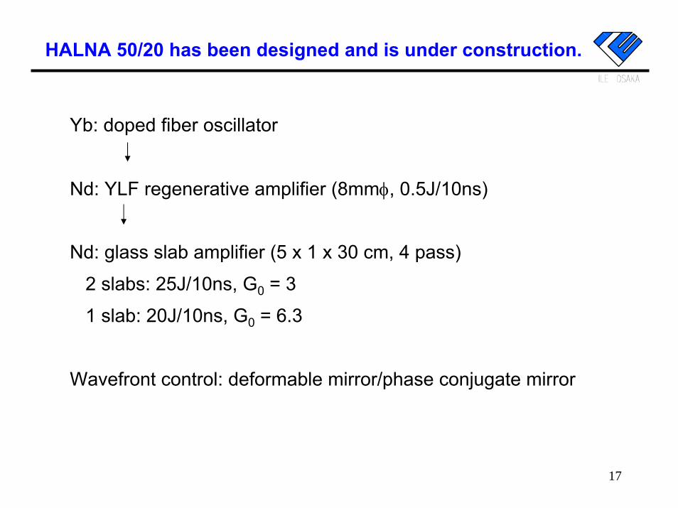
HALNA 50/20 has been designed and is under construction.
Yb: doped fiber oscillator
Nd: YLF regenerative amplifier (8mmφ, 0.5J/10ns)
Nd: glass slab amplifier (5 x 1 x 30 cm, 4 pass)
2 slabs: 25J/10ns, G0 = 3
1 slab: 20J/10ns, G0 = 6.3
Wavefront control: deformable mirror/phase conjugate mirror
17
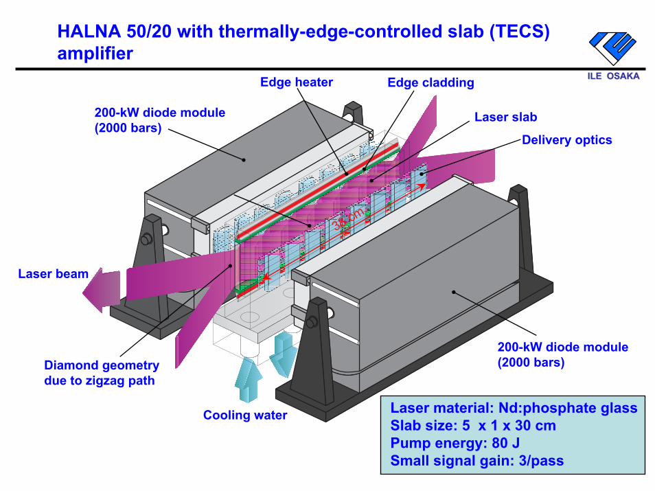
HALNA 50/20 with thermally-edge-controlled slab (TECS) amplifier
18
ILE OSAKAILE OSAKA
200-kW diode module(2000 bars)
200-kW diode module(2000 bars)
Cooling water
Laser slab
Edge claddingEdge heater
Laser beam
Diamond geometrydue to zigzag path
Delivery optics
38 cm
Laser material: Nd:phosphate glassSlab size: 5 x 1 x 30 cmPump energy: 80 JSmall signal gain: 3/pass
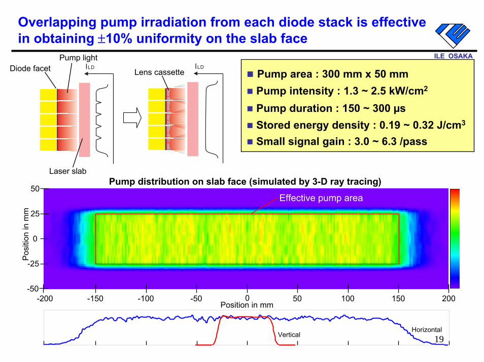
Overlapping pump irradiation from each diode stack is effective in obtaining ±10% uniformity on the slab face
19
50
0-200 -150 -100 -50 50 100 150 200Position in mm
0
25
-50
-25
Pos
ition
in m
m
VerticalHorizontal
ILD ILD
Pump area : 300 mm x 50 mmPump intensity : 1.3 ~ 2.5 kW/cm2
Pump duration : 150 ~ 300 µsStored energy density : 0.19 ~ 0.32 J/cm3
Small signal gain : 3.0 ~ 6.3 /pass
Pump distribution on slab face (simulated by 3-D ray tracing)
Diode facet
Laser slab
Pump light
Lens cassette
Effective pump area
ILE OSAKAILE OSAKA
Summary
� HALNA driver for IFE has been developed.
� The HALNA 10 has achieved 8.4 J at 10 Hz with beam quality of 2 xDLin December, 2004.
� A larger slab amplifier with 5-cm2 aperture has been designed, and it is under construction.
� In 2005, the dual slab system will demonstrate the 20 J x 10 Hz operation with a wavefront correction for the NEDO project.
� In 2006, a half of HALNA 100 will be constructed with 10-cm2 aperture, the 50 J x 10 Hz operation will be the objective of the moment.
20
21
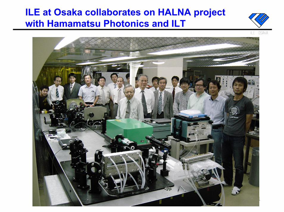
ILE at Osaka collaborates on HALNA project with Hamamatsu Photonics and ILT

22