Design Verification Test Report PART DESCRIPTION IP5-08-01-L-S-RA1-TR...
37
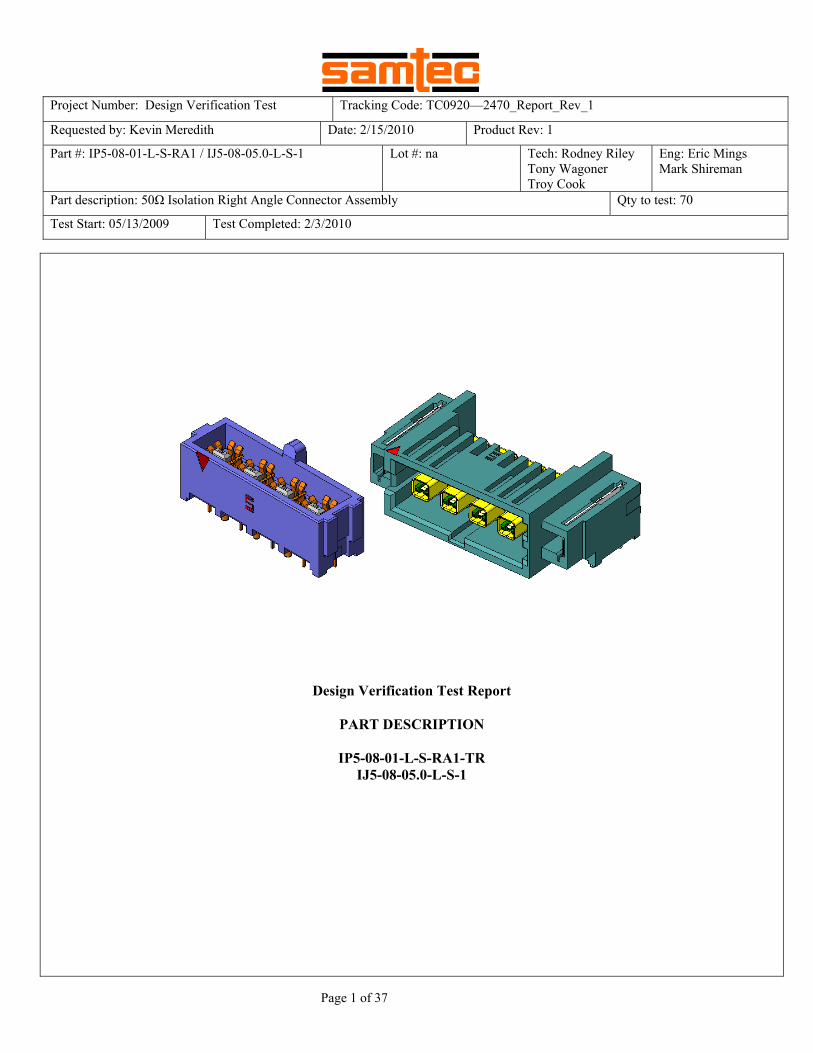
Project Number: Design Verification Test Tracking Code: TC0920—2470_Report_Rev_1 Requested by: Kevin Meredith Date: 2/15/2010 Product Rev: 1 Part #: IP5-08-01-L-S-RA1 / IJ5-08-05.0-L-S-1 Lot #: na Tech: Rodney Riley Tony Wagoner Troy Cook Eng: Eric Mings Mark Shireman Part description: 50Ω Isolation Right Angle Connector Assembly Qty to test: 70 Test Start: 05/13/2009 Test Completed: 2/3/2010 Page 1 of 37 Design Verification Test Report PART DESCRIPTION IP5-08-01-L-S-RA1-TR IJ5-08-05.0-L-S-1
Transcript of Design Verification Test Report PART DESCRIPTION IP5-08-01-L-S-RA1-TR...
Project Number: Design Verification Test Tracking Code: TC0920—2470_Report_Rev_1
Requested by: Kevin Meredith Date: 2/15/2010 Product Rev: 1
Part #: IP5-08-01-L-S-RA1 / IJ5-08-05.0-L-S-1 Lot #: na Tech: Rodney Riley Tony Wagoner Troy Cook
Eng: Eric Mings Mark Shireman
Part description: 50Ω Isolation Right Angle Connector Assembly Qty to test: 70
Test Start: 05/13/2009 Test Completed: 2/3/2010
Page 1 of 37
Design Verification Test Report
PART DESCRIPTION
IP5-08-01-L-S-RA1-TR IJ5-08-05.0-L-S-1
Tracking Code: TC0920—2470_Report_Rev_1 Part #: IP5-08-01-L-S-RA1 / IJ5-08-05.0-L-S-1 Part description: 50Ω Isolation Right Angle Connector Assembly
Page 2 of 37
CERTIFICATION
All instruments and measuring equipment were calibrated to National Institute for Standards and Technology (NIST) traceable standards according to IS0 10012-l and ANSI/NCSL 2540-1, as applicable. All contents contained herein are the property of Samtec. No portion of this report, in part or in full shall be reproduced without prior written approval of Samtec. SCOPE To perform the following tests: Design verification test. See test plan. APPLICABLE DOCUMENTS Standards: EIA Publication 364 TEST SAMPLES AND PREPARATION
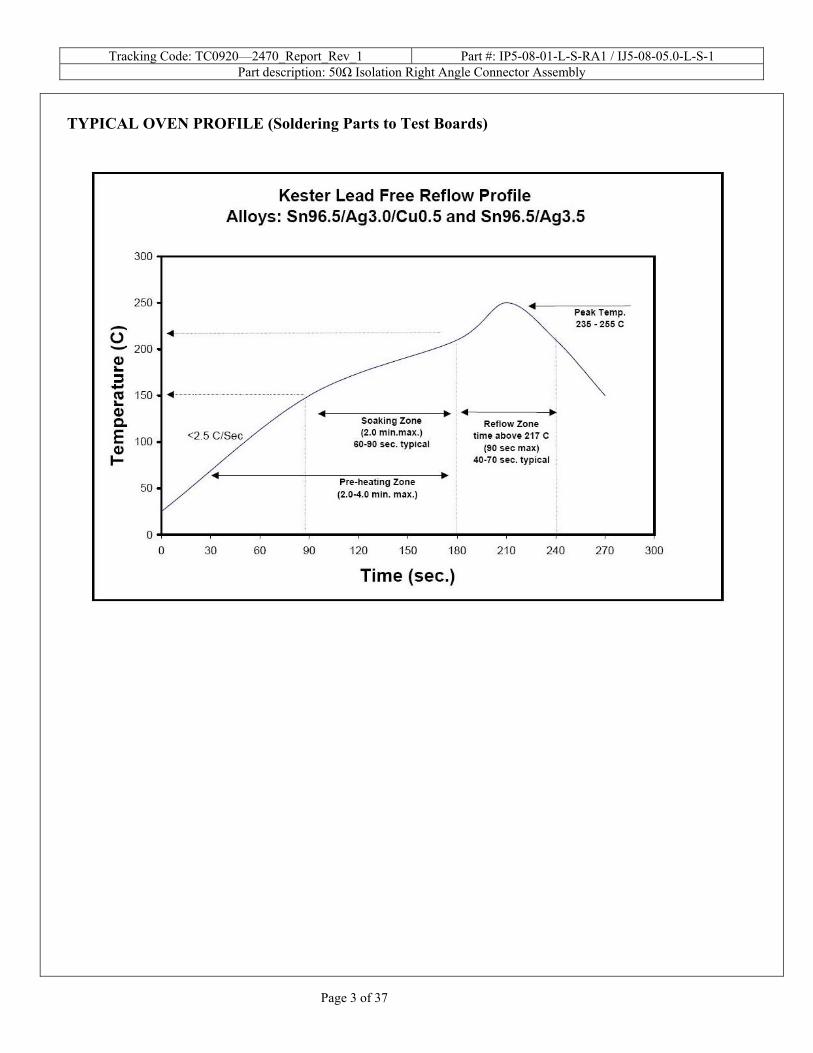
1) All materials were manufactured in accordance with the applicable product specification. 2) All test samples were identified and encoded to maintain traceability throughout the test sequences. 3) After soldering, the parts to be used for LLCR and DWV/IR testing were cleaned according to TLWI-0001. 4) Either an automated cleaning procedure or an ultrasonic cleaning procedure may be used. 5) The automated procedure is used with aqueous compatible soldering materials. 6) Parts not intended for testing LLCR and DWV/IR are visually inspected and cleaned if necessary. 7) Any additional preparation will be noted in the individual test sequences. 8) Solder Information: Lead Free 9) Re-Flow Time/Temp: See accompanying profile. 10) Samtec Test PCBs used: PCB-101798-TST / PCB-101825-TST / PCB-102244-TST
Tracking Code: TC0920—2470_Report_Rev_1 Part #: IP5-08-01-L-S-RA1 / IJ5-08-05.0-L-S-1 Part description: 50Ω Isolation Right Angle Connector Assembly
Page 3 of 37
TYPICAL OVEN PROFILE (Soldering Parts to Test Boards)
Tracking Code: TC0920—2470_Report_Rev_1 Part #: IP5-08-01-L-S-RA1 / IJ5-08-05.0-L-S-1 Part description: 50Ω Isolation Right Angle Connector Assembly
Page 4 of 37
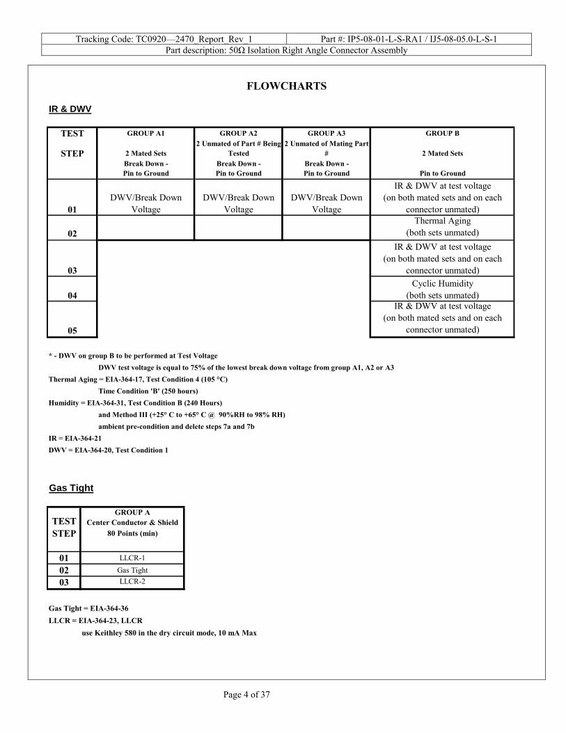
FLOWCHARTS
IR & DWV
TEST GROUP A1 GROUP A2 GROUP A3 GROUP B
STEP 2 Mated Sets2 Unmated of Part # Being
Tested2 Unmated of Mating Part
# 2 Mated SetsBreak Down - Pin to Ground
Break Down - Pin to Ground
Break Down - Pin to Ground Pin to Ground
01DWV/Break Down
Voltage DWV/Break Down
VoltageDWV/Break Down
Voltage
IR & DWV at test voltage(on both mated sets and on each
connector unmated)
02Thermal Aging
(both sets unmated)
03
IR & DWV at test voltage(on both mated sets and on each
connector unmated)
04Cyclic Humidity
(both sets unmated)
05
IR & DWV at test voltage(on both mated sets and on each
connector unmated)
* - DWV on group B to be performed at Test VoltageDWV test voltage is equal to 75% of the lowest break down voltage from group A1, A2 or A3
Thermal Aging = EIA-364-17, Test Condition 4 (105 °C)Time Condition 'B' (250 hours)
Humidity = EIA-364-31, Test Condition B (240 Hours) and Method III (+25° C to +65° C @ 90%RH to 98% RH)ambient pre-condition and delete steps 7a and 7b
IR = EIA-364-21DWV = EIA-364-20, Test Condition 1 Gas Tight
TESTGROUP A
Center Conductor & ShieldSTEP 80 Points (min)
01 LLCR-1
02 Gas Tight
03 LLCR-2
Gas Tight = EIA-364-36LLCR = EIA-364-23, LLCR
use Keithley 580 in the dry circuit mode, 10 mA Max
Tracking Code: TC0920—2470_Report_Rev_1 Part #: IP5-08-01-L-S-RA1 / IJ5-08-05.0-L-S-1 Part description: 50Ω Isolation Right Angle Connector Assembly
Page 5 of 37
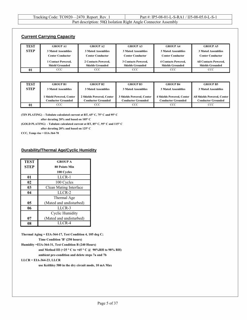
Current Carrying Capacity
TEST GROUP A1 GROUP A2 GROUP A3 GROUP A4 GROUP A5
STEP 3 Mated Assemblies 3 Mated Assemblies 3 Mated Assemblies 3 Mated Assemblies 3 Mated AssembliesCenter Conductor Center Conductor Center Conductor Center Conductor Center Conductor
1 Contact Powered,Shield Grounded
2 Contacts Powered,Shields Grounded
3 Contacts Powered,Shields Grounded
4 Contacts Powered,Shields Grounded
All Contacts Powered,Shields Grounded
01 CCC CCC CCC CCC CCC
TEST GROUP B1 GROUP B2 GROUP B3 GROUP B4 GROUP B5
STEP 3 Mated Assemblies 3 Mated Assemblies 3 Mated Assemblies 3 Mated Assemblies 3 Mated Assemblies
1 Shield Powered, Center Conductor Grounded
2 Shields Powered, Center Conductor Grounded
3 Shields Powered, Center Conductor Grounded
4 Shields Powered, Center Conductor Grounded
All Shields Powered, Center Conductor Grounded
01 CCC CCC CCC CCC CCC
(TIN PLATING) - Tabulate calculated current at RT, 65° C, 75° C and 95° Cafter derating 20% and based on 105° C
after derating 20% and based on 125° CCCC, Temp rise = EIA-364-70
(GOLD PLATING) - Tabulate calculated current at RT, 85° C, 95° C and 115° C
Durability/Thermal Age/Cyclic Humidity
TEST GROUP A
STEP 80 Points Min100 Cycles
01 LLCR-102 100 Cycles03 Clean Mating Interface04 LLCR-2
05Thermal Age
(Mated and undisturbed)06 LLCR-3
07Cyclic Humidity
(Mated and undisturbed)08 LLCR-4
Thermal Aging = EIA-364-17, Test Condition 4, 105 deg C;Time Condition 'B' (250 hours)
Humidity =EIA-364-31, Test Condition B (240 Hours) and Method III (+25 ° C to +65 ° C @ 90%RH to 98% RH)ambient pre-condition and delete steps 7a and 7b
LLCR = EIA-364-23, LLCRuse Keithley 580 in the dry circuit mode, 10 mA Max
Tracking Code: TC0920—2470_Report_Rev_1 Part #: IP5-08-01-L-S-RA1 / IJ5-08-05.0-L-S-1 Part description: 50Ω Isolation Right Angle Connector Assembly
Page 6 of 37
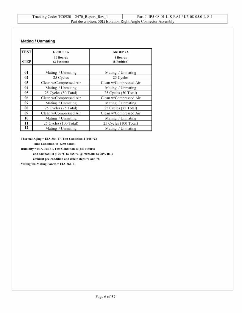
Mating / Unmating
TEST GROUP 1A GROUP 2A
STEP10 Boards
(2 Position)4 Boards
(8 Position)
01 Mating / Unmating Mating / Unmating02 25 Cycles 25 Cycles 03 Clean w/Compressed Air Clean w/Compressed Air04 Mating / Unmating Mating / Unmating05 25 Cycles (50 Total) 25 Cycles (50 Total)06 Clean w/Compressed Air Clean w/Compressed Air07 Mating / Unmating Mating / Unmating08 25 Cycles (75 Total) 25 Cycles (75 Total)09 Clean w/Compressed Air Clean w/Compressed Air10 Mating / Unmating Mating / Unmating11 25 Cycles (100 Total) 25 Cycles (100 Total)12 Mating / Unmating Mating / Unmating
Thermal Aging = EIA-364-17, Test Condition 4 (105 °C)Time Condition 'B' (250 hours)
Humidity = EIA-364-31, Test Condition B (240 Hours) and Method III (+25 °C to +65 °C @ 90%RH to 98% RH)ambient pre-condition and delete steps 7a and 7b
Mating/Un-Mating Forces = EIA-364-13
Tracking Code: TC0920—2470_Report_Rev_1 Part #: IP5-08-01-L-S-RA1 / IJ5-08-05.0-L-S-1 Part description: 50Ω Isolation Right Angle Connector Assembly
Page 7 of 37
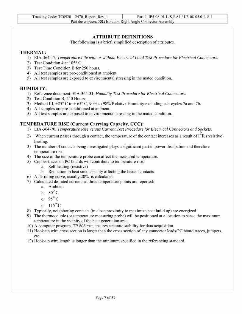
ATTRIBUTE DEFINITIONS
The following is a brief, simplified description of attributes. THERMAL:
1) EIA-364-17, Temperature Life with or without Electrical Load Test Procedure for Electrical Connectors. 2) Test Condition 4 at 105° C. 3) Test Time Condition B for 250 hours. 4) All test samples are pre-conditioned at ambient. 5) All test samples are exposed to environmental stressing in the mated condition.
HUMIDITY:
1) Reference document: EIA-364-31, Humidity Test Procedure for Electrical Connectors. 2) Test Condition B, 240 Hours. 3) Method III, +25° C to + 65° C, 90% to 98% Relative Humidity excluding sub-cycles 7a and 7b. 4) All samples are pre-conditioned at ambient. 5) All test samples are exposed to environmental stressing in the mated condition.
TEMPERATURE RISE (Current Carrying Capacity, CCC):
1) EIA-364-70, Temperature Rise versus Current Test Procedure for Electrical Connectors and Sockets. 2) When current passes through a contact, the temperature of the contact increases as a result of I2R (resistive)
heating. 3) The number of contacts being investigated plays a significant part in power dissipation and therefore
temperature rise. 4) The size of the temperature probe can affect the measured temperature. 5) Copper traces on PC boards will contribute to temperature rise:
a. Self heating (resistive) b. Reduction in heat sink capacity affecting the heated contacts
6) A de-rating curve, usually 20%, is calculated. 7) Calculated de-rated currents at three temperature points are reported:
a. Ambient b. 80о C c. 95о C d. 115о C
8) Typically, neighboring contacts (in close proximity to maximize heat build up) are energized. 9) The thermocouple (or temperature measuring probe) will be positioned at a location to sense the maximum
temperature in the vicinity of the heat generation area. 10) A computer program, TR 803.exe, ensures accurate stability for data acquisition. 11) Hook-up wire cross section is larger than the cross section of any connector leads/PC board traces, jumpers,
etc. 12) Hook-up wire length is longer than the minimum specified in the referencing standard.
Tracking Code: TC0920—2470_Report_Rev_1 Part #: IP5-08-01-L-S-RA1 / IJ5-08-05.0-L-S-1 Part description: 50Ω Isolation Right Angle Connector Assembly
Page 8 of 37
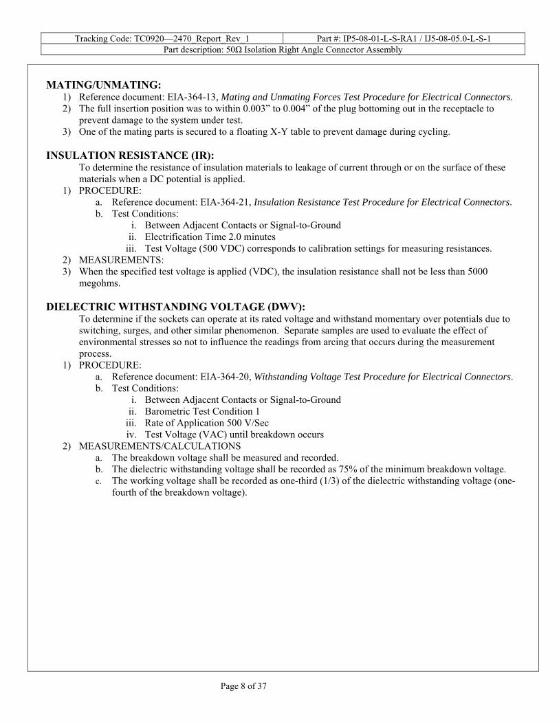
MATING/UNMATING:
1) Reference document: EIA-364-13, Mating and Unmating Forces Test Procedure for Electrical Connectors. 2) The full insertion position was to within 0.003” to 0.004” of the plug bottoming out in the receptacle to
prevent damage to the system under test. 3) One of the mating parts is secured to a floating X-Y table to prevent damage during cycling.
INSULATION RESISTANCE (IR):
To determine the resistance of insulation materials to leakage of current through or on the surface of these materials when a DC potential is applied.
1) PROCEDURE: a. Reference document: EIA-364-21, Insulation Resistance Test Procedure for Electrical Connectors. b. Test Conditions:
i. Between Adjacent Contacts or Signal-to-Ground ii. Electrification Time 2.0 minutes
iii. Test Voltage (500 VDC) corresponds to calibration settings for measuring resistances. 2) MEASUREMENTS: 3) When the specified test voltage is applied (VDC), the insulation resistance shall not be less than 5000
megohms. DIELECTRIC WITHSTANDING VOLTAGE (DWV):
To determine if the sockets can operate at its rated voltage and withstand momentary over potentials due to switching, surges, and other similar phenomenon. Separate samples are used to evaluate the effect of environmental stresses so not to influence the readings from arcing that occurs during the measurement process.
1) PROCEDURE: a. Reference document: EIA-364-20, Withstanding Voltage Test Procedure for Electrical Connectors. b. Test Conditions:
i. Between Adjacent Contacts or Signal-to-Ground ii. Barometric Test Condition 1
iii. Rate of Application 500 V/Sec iv. Test Voltage (VAC) until breakdown occurs
2) MEASUREMENTS/CALCULATIONS a. The breakdown voltage shall be measured and recorded. b. The dielectric withstanding voltage shall be recorded as 75% of the minimum breakdown voltage. c. The working voltage shall be recorded as one-third (1/3) of the dielectric withstanding voltage (one-
fourth of the breakdown voltage).
Tracking Code: TC0920—2470_Report_Rev_1 Part #: IP5-08-01-L-S-RA1 / IJ5-08-05.0-L-S-1 Part description: 50Ω Isolation Right Angle Connector Assembly
Page 9 of 37
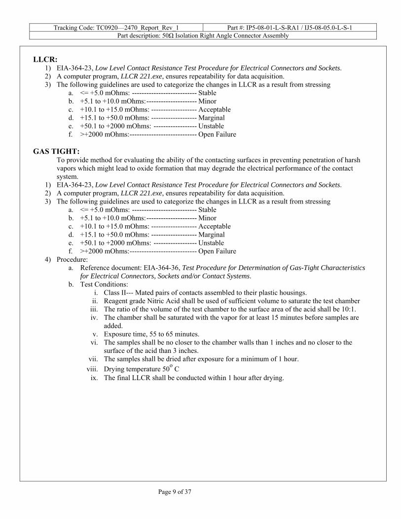
LLCR:
1) EIA-364-23, Low Level Contact Resistance Test Procedure for Electrical Connectors and Sockets. 2) A computer program, LLCR 221.exe, ensures repeatability for data acquisition. 3) The following guidelines are used to categorize the changes in LLCR as a result from stressing
a. <= +5.0 mOhms: --------------------------- Stable b. +5.1 to +10.0 mOhms:--------------------- Minor c. +10.1 to +15.0 mOhms: ------------------- Acceptable d. +15.1 to +50.0 mOhms: ------------------- Marginal e. +50.1 to +2000 mOhms: ------------------ Unstable f. >+2000 mOhms:---------------------------- Open Failure
GAS TIGHT:
To provide method for evaluating the ability of the contacting surfaces in preventing penetration of harsh vapors which might lead to oxide formation that may degrade the electrical performance of the contact system.
1) EIA-364-23, Low Level Contact Resistance Test Procedure for Electrical Connectors and Sockets. 2) A computer program, LLCR 221.exe, ensures repeatability for data acquisition. 3) The following guidelines are used to categorize the changes in LLCR as a result from stressing
a. <= +5.0 mOhms: --------------------------- Stable b. +5.1 to +10.0 mOhms:--------------------- Minor c. +10.1 to +15.0 mOhms: ------------------- Acceptable d. +15.1 to +50.0 mOhms: ------------------- Marginal e. +50.1 to +2000 mOhms: ------------------ Unstable f. >+2000 mOhms:---------------------------- Open Failure
4) Procedure: a. Reference document: EIA-364-36, Test Procedure for Determination of Gas-Tight Characteristics
for Electrical Connectors, Sockets and/or Contact Systems. b. Test Conditions:
i. Class II--- Mated pairs of contacts assembled to their plastic housings. ii. Reagent grade Nitric Acid shall be used of sufficient volume to saturate the test chamber
iii. The ratio of the volume of the test chamber to the surface area of the acid shall be 10:1. iv. The chamber shall be saturated with the vapor for at least 15 minutes before samples are
added. v. Exposure time, 55 to 65 minutes.
vi. The samples shall be no closer to the chamber walls than 1 inches and no closer to the surface of the acid than 3 inches.
vii. The samples shall be dried after exposure for a minimum of 1 hour. viii. Drying temperature 50о C
ix. The final LLCR shall be conducted within 1 hour after drying.
Tracking Code: TC0920—2470_Report_Rev_1 Part #: IP5-08-01-L-S-RA1 / IJ5-08-05.0-L-S-1 Part description: 50Ω Isolation Right Angle Connector Assembly
Page 10 of 37
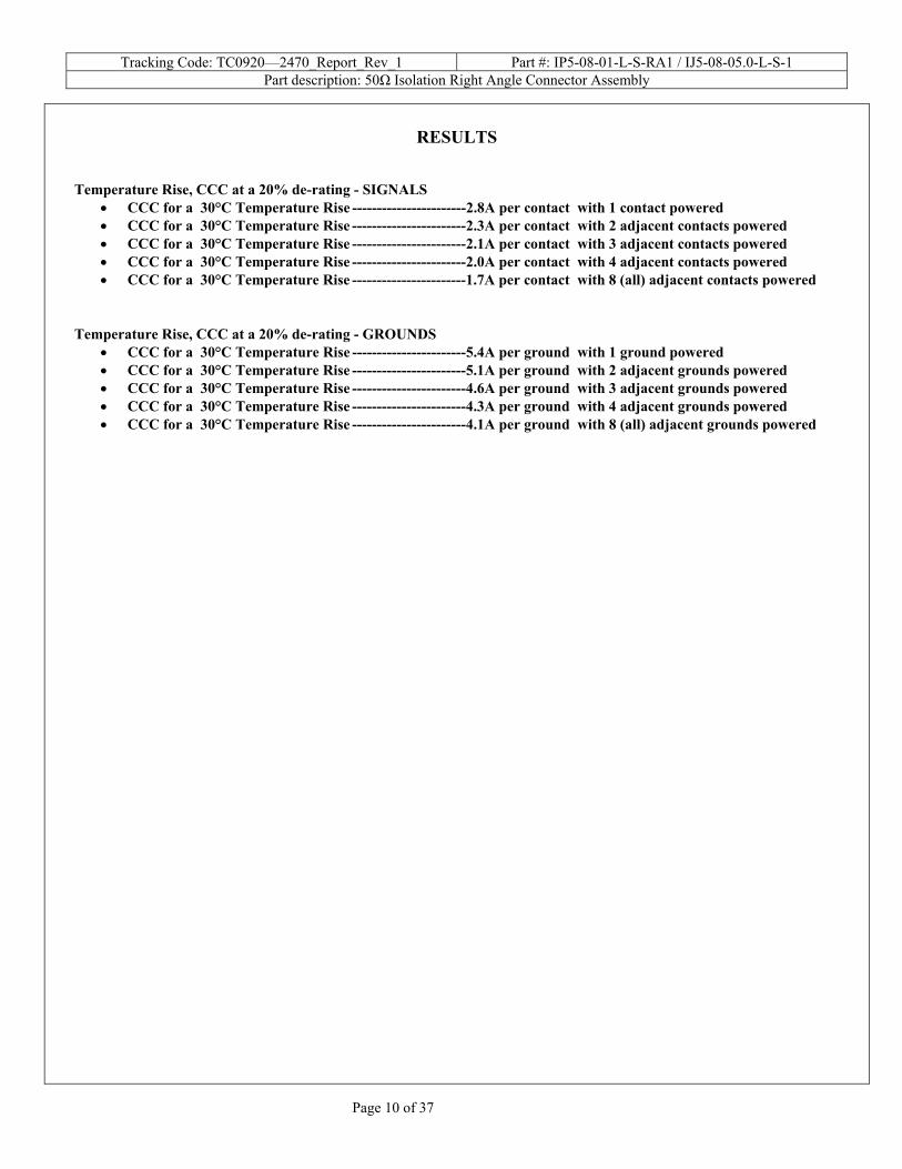
RESULTS
Temperature Rise, CCC at a 20% de-rating - SIGNALS
• CCC for a 30°C Temperature Rise -----------------------2.8A per contact with 1 contact powered • CCC for a 30°C Temperature Rise -----------------------2.3A per contact with 2 adjacent contacts powered • CCC for a 30°C Temperature Rise -----------------------2.1A per contact with 3 adjacent contacts powered • CCC for a 30°C Temperature Rise -----------------------2.0A per contact with 4 adjacent contacts powered • CCC for a 30°C Temperature Rise -----------------------1.7A per contact with 8 (all) adjacent contacts powered
Temperature Rise, CCC at a 20% de-rating - GROUNDS • CCC for a 30°C Temperature Rise -----------------------5.4A per ground with 1 ground powered • CCC for a 30°C Temperature Rise -----------------------5.1A per ground with 2 adjacent grounds powered • CCC for a 30°C Temperature Rise -----------------------4.6A per ground with 3 adjacent grounds powered • CCC for a 30°C Temperature Rise -----------------------4.3A per ground with 4 adjacent grounds powered • CCC for a 30°C Temperature Rise -----------------------4.1A per ground with 8 (all) adjacent grounds powered
Tracking Code: TC0920—2470_Report_Rev_1 Part #: IP5-08-01-L-S-RA1 / IJ5-08-05.0-L-S-1 Part description: 50Ω Isolation Right Angle Connector Assembly
Page 11 of 37
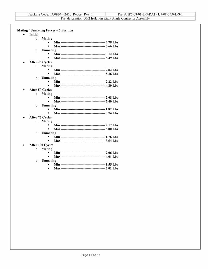
Mating / Unmating Forces – 2 Position
• Initial o Mating
Min --------------------------------------- 3.78 Lbs Max--------------------------------------- 5.66 Lbs
o Unmating Min --------------------------------------- 3.12 Lbs Max--------------------------------------- 5.49 Lbs
• After 25 Cycles o Mating
Min --------------------------------------- 2.82 Lbs Max--------------------------------------- 5.36 Lbs
o Unmating Min --------------------------------------- 2.22 Lbs Max--------------------------------------- 4.80 Lbs
• After 50 Cycles o Mating
Min --------------------------------------- 2.68 Lbs Max--------------------------------------- 5.40 Lbs
o Unmating Min --------------------------------------- 1.82 Lbs Max--------------------------------------- 3.74 Lbs
• After 75 Cycles o Mating
Min --------------------------------------- 2.17 Lbs Max--------------------------------------- 5.00 Lbs
o Unmating Min --------------------------------------- 1.76 Lbs Max--------------------------------------- 3.54 Lbs
• After 100 Cycles o Mating
Min --------------------------------------- 2.06 Lbs Max--------------------------------------- 4.01 Lbs
o Unmating Min --------------------------------------- 1.55 Lbs Max--------------------------------------- 3.01 Lbs

Tracking Code: TC0920—2470_Report_Rev_1 Part #: IP5-08-01-L-S-RA1 / IJ5-08-05.0-L-S-1 Part description: 50Ω Isolation Right Angle Connector Assembly
Page 12 of 37
Mating / Unmating Forces – 8 Position
• Initial o Mating
Min --------------------------------------17.61 Lbs Max--------------------------------------19.74 Lbs
o Unmating Min --------------------------------------16.59 Lbs Max--------------------------------------19.64 Lbs
• After 25 Cycles o Mating
Min --------------------------------------14.81 Lbs Max--------------------------------------17.24 Lbs
o Unmating Min --------------------------------------14.45 Lbs Max--------------------------------------17.83 Lbs
• After 50 Cycles o Mating
Min --------------------------------------10.97 Lbs Max--------------------------------------15.45 Lbs
o Unmating Min --------------------------------------11.90 Lbs Max--------------------------------------15.58 Lbs
• After 75 Cycles o Mating
Min --------------------------------------10.12 Lbs Max--------------------------------------14.24 Lbs
o Unmating Min --------------------------------------10.35 Lbs Max--------------------------------------14.19 Lbs
• After 100 Cycles o Mating
Min --------------------------------------- 9.86 Lbs Max--------------------------------------14.30 Lbs
o Unmating Min --------------------------------------- 9.59 Lbs Max--------------------------------------12.93 Lbs
Tracking Code: TC0920—2470_Report_Rev_1 Part #: IP5-08-01-L-S-RA1 / IJ5-08-05.0-L-S-1 Part description: 50Ω Isolation Right Angle Connector Assembly
Page 13 of 37
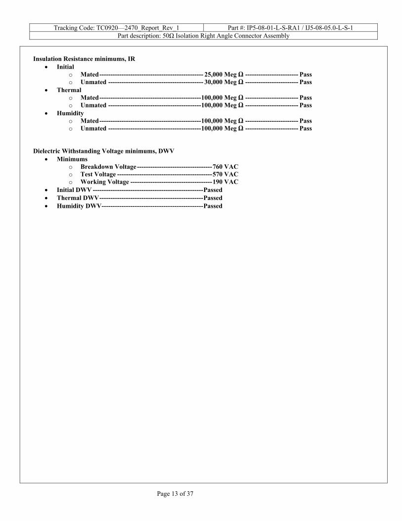
Insulation Resistance minimums, IR
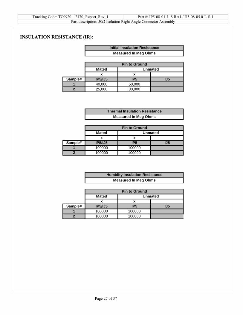
• Initial o Mated----------------------------------------------- 25,000 Meg Ω ------------------------ Pass o Unmated ------------------------------------------- 30,000 Meg Ω ------------------------ Pass
• Thermal o Mated----------------------------------------------100,000 Meg Ω ------------------------ Pass o Unmated ------------------------------------------100,000 Meg Ω ------------------------ Pass
• Humidity o Mated----------------------------------------------100,000 Meg Ω ------------------------ Pass o Unmated ------------------------------------------100,000 Meg Ω ------------------------ Pass
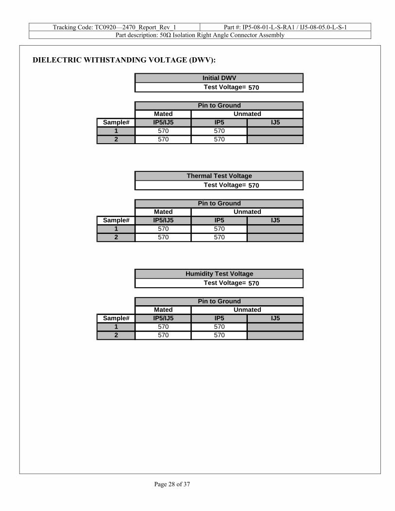
Dielectric Withstanding Voltage minimums, DWV
• Minimums o Breakdown Voltage----------------------------------760 VAC o Test Voltage -------------------------------------------570 VAC o Working Voltage -------------------------------------190 VAC
• Initial DWV --------------------------------------------------Passed • Thermal DWV-----------------------------------------------Passed • Humidity DWV----------------------------------------------Passed
Tracking Code: TC0920—2470_Report_Rev_1 Part #: IP5-08-01-L-S-RA1 / IJ5-08-05.0-L-S-1 Part description: 50Ω Isolation Right Angle Connector Assembly
Page 14 of 37
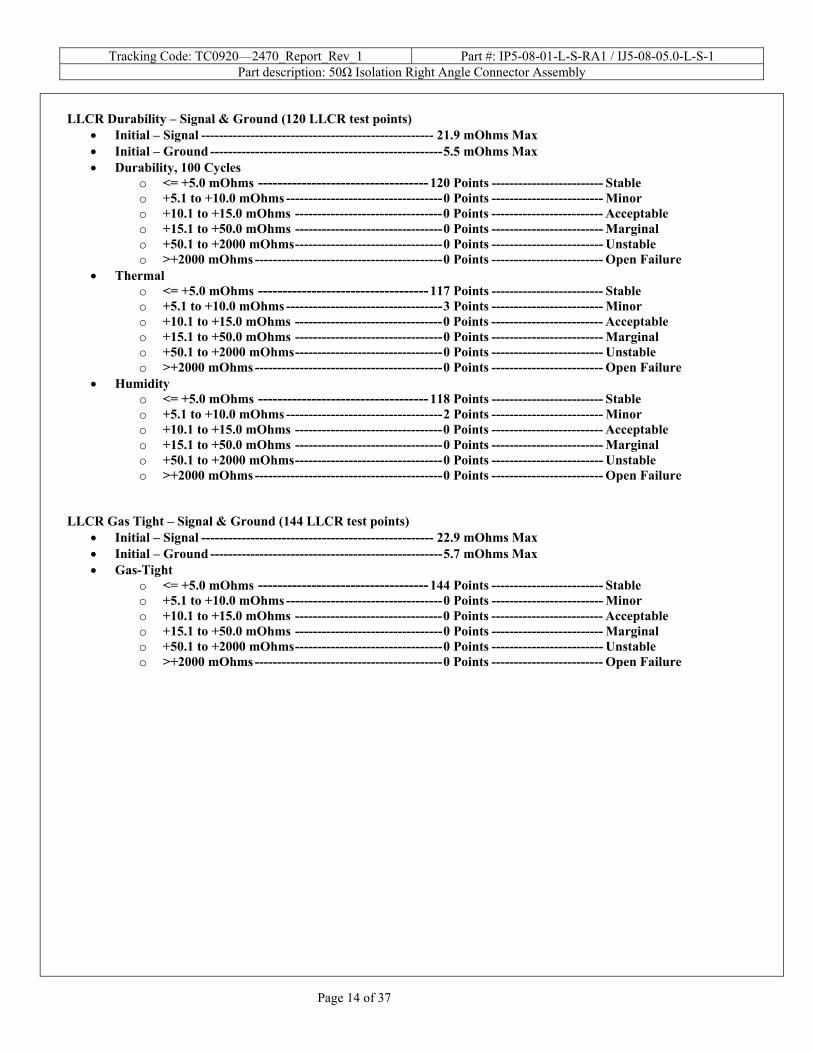
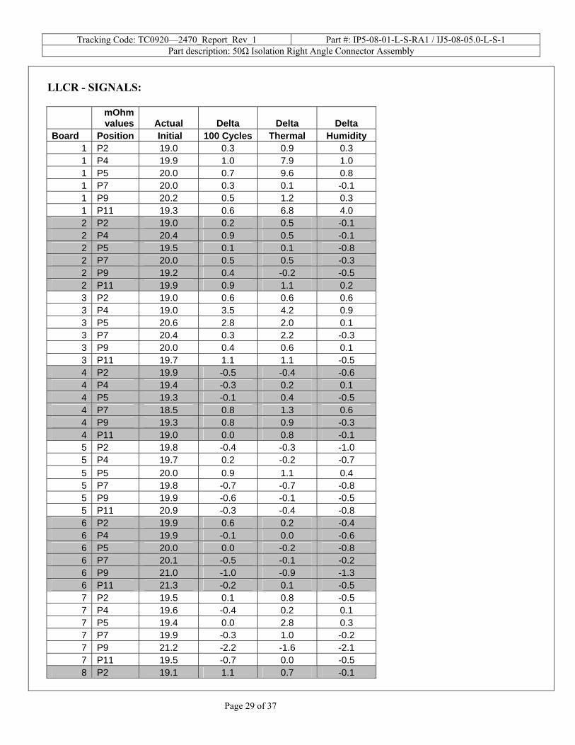
LLCR Durability – Signal & Ground (120 LLCR test points)
• Initial – Signal ---------------------------------------------------- 21.9 mOhms Max • Initial – Ground ----------------------------------------------------5.5 mOhms Max • Durability, 100 Cycles
o <= +5.0 mOhms -----------------------------------120 Points ------------------------- Stable o +5.1 to +10.0 mOhms -----------------------------------0 Points ------------------------- Minor o +10.1 to +15.0 mOhms ---------------------------------0 Points ------------------------- Acceptable o +15.1 to +50.0 mOhms ---------------------------------0 Points ------------------------- Marginal o +50.1 to +2000 mOhms---------------------------------0 Points ------------------------- Unstable o >+2000 mOhms ------------------------------------------0 Points ------------------------- Open Failure
• Thermal o <= +5.0 mOhms -----------------------------------117 Points ------------------------- Stable o +5.1 to +10.0 mOhms -----------------------------------3 Points ------------------------- Minor o +10.1 to +15.0 mOhms ---------------------------------0 Points ------------------------- Acceptable o +15.1 to +50.0 mOhms ---------------------------------0 Points ------------------------- Marginal o +50.1 to +2000 mOhms---------------------------------0 Points ------------------------- Unstable o >+2000 mOhms ------------------------------------------0 Points ------------------------- Open Failure
• Humidity o <= +5.0 mOhms -----------------------------------118 Points ------------------------- Stable o +5.1 to +10.0 mOhms -----------------------------------2 Points ------------------------- Minor o +10.1 to +15.0 mOhms ---------------------------------0 Points ------------------------- Acceptable o +15.1 to +50.0 mOhms ---------------------------------0 Points ------------------------- Marginal o +50.1 to +2000 mOhms---------------------------------0 Points ------------------------- Unstable o >+2000 mOhms ------------------------------------------0 Points ------------------------- Open Failure
LLCR Gas Tight – Signal & Ground (144 LLCR test points)
• Initial – Signal ---------------------------------------------------- 22.9 mOhms Max • Initial – Ground ----------------------------------------------------5.7 mOhms Max • Gas-Tight
o <= +5.0 mOhms -----------------------------------144 Points ------------------------- Stable o +5.1 to +10.0 mOhms -----------------------------------0 Points ------------------------- Minor o +10.1 to +15.0 mOhms ---------------------------------0 Points ------------------------- Acceptable o +15.1 to +50.0 mOhms ---------------------------------0 Points ------------------------- Marginal o +50.1 to +2000 mOhms---------------------------------0 Points ------------------------- Unstable o >+2000 mOhms ------------------------------------------0 Points ------------------------- Open Failure
Tracking Code: TC0920—2470_Report_Rev_1 Part #: IP5-08-01-L-S-RA1 / IJ5-08-05.0-L-S-1 Part description: 50Ω Isolation Right Angle Connector Assembly
Page 15 of 37
DATA SUMMARIES
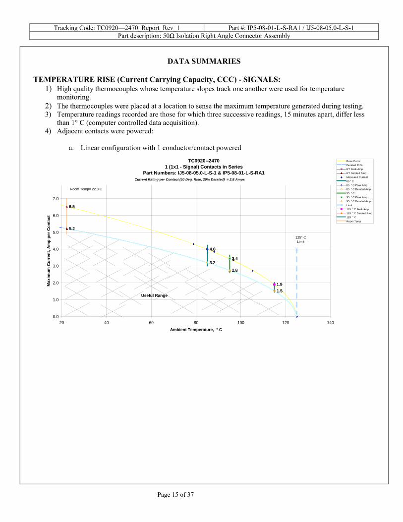
TEMPERATURE RISE (Current Carrying Capacity, CCC) - SIGNALS:
1) High quality thermocouples whose temperature slopes track one another were used for temperature monitoring.
2) The thermocouples were placed at a location to sense the maximum temperature generated during testing. 3) Temperature readings recorded are those for which three successive readings, 15 minutes apart, differ less
than 1° C (computer controlled data acquisition). 4) Adjacent contacts were powered:
a. Linear configuration with 1 conductor/contact powered
TC0920--24701 (1x1 - Signal) Contacts in Series
Part Numbers: IJ5-08-05.0-L-S-1 & IP5-08-01-L-S-RA1
6.56.5
5.25.2
4.04.0
3.23.23.43.4
2.82.8
1.91.91.51.5
0.0
1.0
2.0
3.0
4.0
5.0
6.0
7.0
20 40 60 80 100 120 140
Ambient Temperature, ° C
Max
imum
Cur
rent
, Am
p pe
r Con
tact
Base CurveDerated 20 %RT Peak AmpRT Derated AmpMeasured Current85 ° C85 ° C Peak Amp85 ° C Derated Amp95 ° C95 ° C Peak Amp95 ° C Derated AmpLimit115 ° C Peak Amp115 ° C Derated Amp115 ° CRoom Temp
125° CLimit
Useful Range
Room Temp= 22.3 C
Current Rating per Contact (30 Deg. Rise, 20% Derated) = 2.8 Amps
Tracking Code: TC0920—2470_Report_Rev_1 Part #: IP5-08-01-L-S-RA1 / IJ5-08-05.0-L-S-1 Part description: 50Ω Isolation Right Angle Connector Assembly
Page 16 of 37
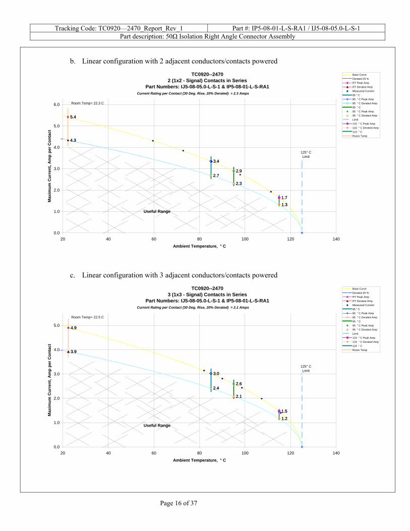
b. Linear configuration with 2 adjacent conductors/contacts powered
TC0920--24702 (1x2 - Signal) Contacts in Series
Part Numbers: IJ5-08-05.0-L-S-1 & IP5-08-01-L-S-RA1
5.45.4
4.34.3
3.43.4
2.72.72.92.9
2.32.3
1.71.7
1.31.3
0.0
1.0
2.0
3.0
4.0
5.0
6.0
20 40 60 80 100 120 140
Ambient Temperature, ° C
Max
imum
Cur
rent
, Am
p pe
r Con
tact
Base CurveDerated 20 %RT Peak AmpRT Derated AmpMeasured Current85 ° C85 ° C Peak Amp85 ° C Derated Amp95 ° C95 ° C Peak Amp95 ° C Derated AmpLimit115 ° C Peak Amp115 ° C Derated Amp115 ° CRoom Temp
125° CLimit
Useful Range
Room Temp= 22.3 C
Current Rating per Contact (30 Deg. Rise, 20% Derated) = 2.3 Amps
c. Linear configuration with 3 adjacent conductors/contacts powered
TC0920--24703 (1x3 - Signal) Contacts in Series
Part Numbers: IJ5-08-05.0-L-S-1 & IP5-08-01-L-S-RA1
4.94.9
3.93.9
3.03.0
2.42.42.62.6
2.12.1
1.51.5
1.21.2
0.0
1.0
2.0
3.0
4.0
5.0
20 40 60 80 100 120 140
Ambient Temperature, ° C
Max
imum
Cur
rent
, Am
p pe
r Con
tact
Base CurveDerated 20 %RT Peak AmpRT Derated AmpMeasured Current85 ° C85 ° C Peak Amp85 ° C Derated Amp95 ° C95 ° C Peak Amp95 ° C Derated AmpLimit115 ° C Peak Amp115 ° C Derated Amp115 ° CRoom Temp
125° CLimit
Useful Range
Room Temp= 22.5 C
Current Rating per Contact (30 Deg. Rise, 20% Derated) = 2.1 Amps
Tracking Code: TC0920—2470_Report_Rev_1 Part #: IP5-08-01-L-S-RA1 / IJ5-08-05.0-L-S-1 Part description: 50Ω Isolation Right Angle Connector Assembly
Page 17 of 37
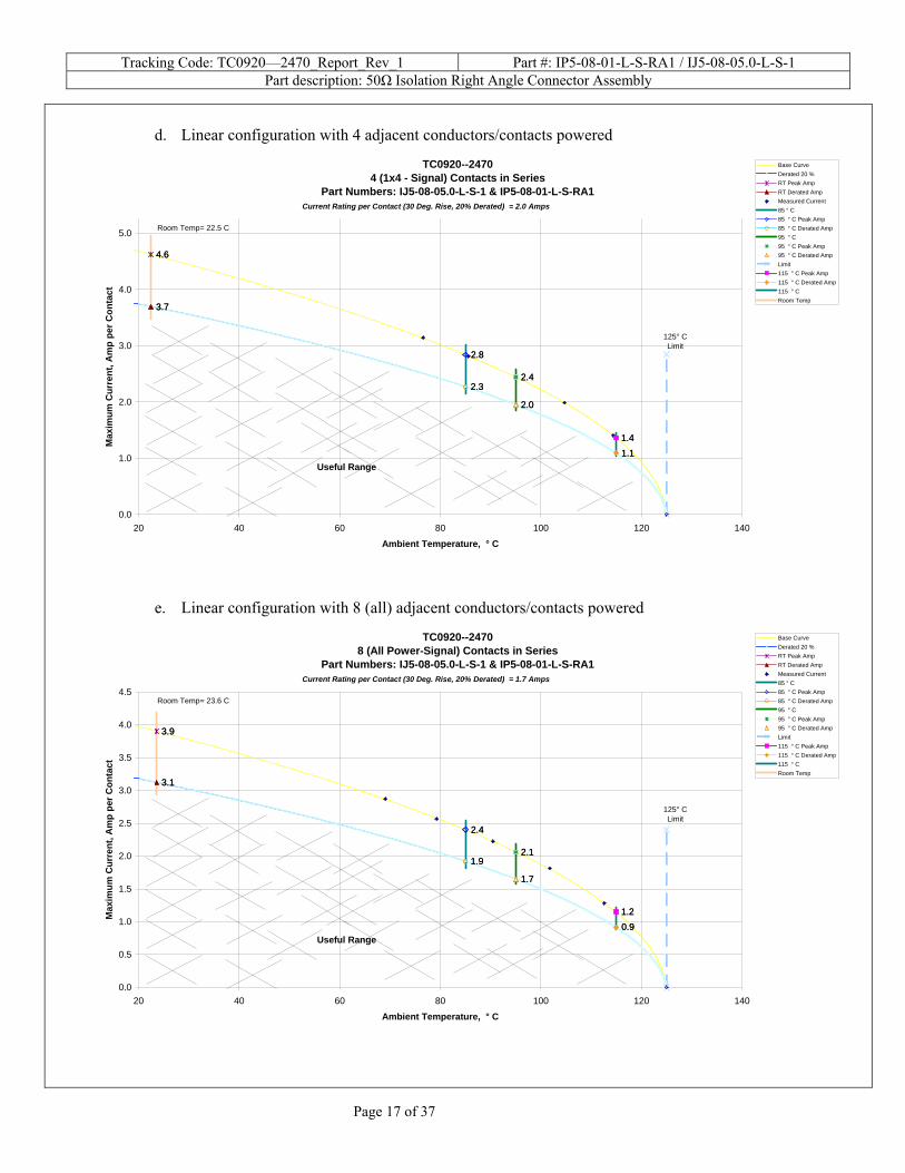
d. Linear configuration with 4 adjacent conductors/contacts powered
TC0920--24704 (1x4 - Signal) Contacts in Series
Part Numbers: IJ5-08-05.0-L-S-1 & IP5-08-01-L-S-RA1
4.64.6
3.73.7
2.82.8
2.32.32.42.4
2.02.0
1.41.41.11.1
0.0
1.0
2.0
3.0
4.0
5.0
20 40 60 80 100 120 140
Ambient Temperature, ° C
Max
imum
Cur
rent
, Am
p pe
r Con
tact
Base CurveDerated 20 %RT Peak AmpRT Derated AmpMeasured Current85 ° C85 ° C Peak Amp85 ° C Derated Amp95 ° C95 ° C Peak Amp95 ° C Derated AmpLimit115 ° C Peak Amp115 ° C Derated Amp115 ° CRoom Temp
125° CLimit
Useful Range
Room Temp= 22.5 C
Current Rating per Contact (30 Deg. Rise, 20% Derated) = 2.0 Amps
e. Linear configuration with 8 (all) adjacent conductors/contacts powered
TC0920--24708 (All Power-Signal) Contacts in Series
Part Numbers: IJ5-08-05.0-L-S-1 & IP5-08-01-L-S-RA1
3.93.9
3.13.1
2.42.4
1.91.92.12.1
1.71.7
1.21.20.90.9
0.0
0.5
1.0
1.5
2.0
2.5
3.0
3.5
4.0
4.5
20 40 60 80 100 120 140
Ambient Temperature, ° C
Max
imum
Cur
rent
, Am
p pe
r Con
tact
Base CurveDerated 20 %RT Peak AmpRT Derated AmpMeasured Current85 ° C85 ° C Peak Amp85 ° C Derated Amp95 ° C95 ° C Peak Amp95 ° C Derated AmpLimit115 ° C Peak Amp115 ° C Derated Amp115 ° CRoom Temp
125° CLimit
Useful Range
Room Temp= 23.6 C
Current Rating per Contact (30 Deg. Rise, 20% Derated) = 1.7 Amps
Tracking Code: TC0920—2470_Report_Rev_1 Part #: IP5-08-01-L-S-RA1 / IJ5-08-05.0-L-S-1 Part description: 50Ω Isolation Right Angle Connector Assembly
Page 18 of 37
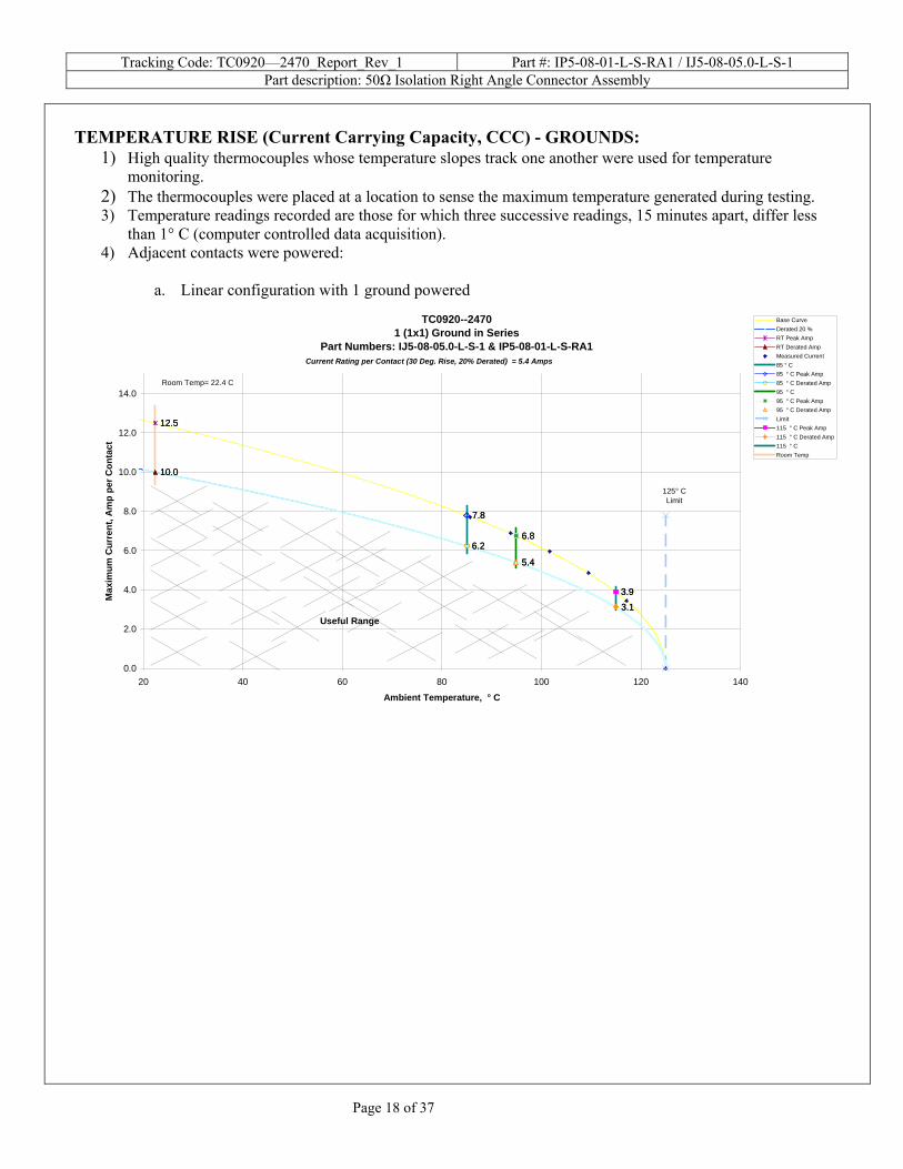
TEMPERATURE RISE (Current Carrying Capacity, CCC) - GROUNDS:
1) High quality thermocouples whose temperature slopes track one another were used for temperature monitoring.
2) The thermocouples were placed at a location to sense the maximum temperature generated during testing. 3) Temperature readings recorded are those for which three successive readings, 15 minutes apart, differ less
than 1° C (computer controlled data acquisition). 4) Adjacent contacts were powered:
a. Linear configuration with 1 ground powered
TC0920--24701 (1x1) Ground in Series
Part Numbers: IJ5-08-05.0-L-S-1 & IP5-08-01-L-S-RA1
12.512.5
10.010.0
7.87.8
6.26.26.86.8
5.45.4
3.93.93.13.1
0.0
2.0
4.0
6.0
8.0
10.0
12.0
14.0
20 40 60 80 100 120 140
Ambient Temperature, ° C
Max
imum
Cur
rent
, Am
p pe
r Con
tact
Base CurveDerated 20 %RT Peak AmpRT Derated AmpMeasured Current85 ° C85 ° C Peak Amp85 ° C Derated Amp95 ° C95 ° C Peak Amp95 ° C Derated AmpLimit115 ° C Peak Amp115 ° C Derated Amp115 ° CRoom Temp
125° CLimit
Useful Range
Room Temp= 22.4 C
Current Rating per Contact (30 Deg. Rise, 20% Derated) = 5.4 Amps
Tracking Code: TC0920—2470_Report_Rev_1 Part #: IP5-08-01-L-S-RA1 / IJ5-08-05.0-L-S-1 Part description: 50Ω Isolation Right Angle Connector Assembly
Page 19 of 37
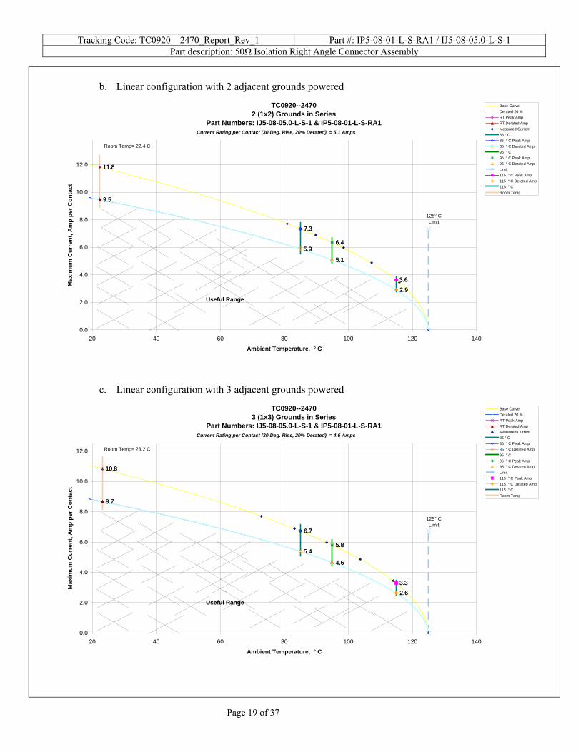
b. Linear configuration with 2 adjacent grounds powered
TC0920--24702 (1x2) Grounds in Series
Part Numbers: IJ5-08-05.0-L-S-1 & IP5-08-01-L-S-RA1
11.811.8
9.59.5
7.37.3
5.95.96.46.4
5.15.1
3.63.6
2.92.9
0.0
2.0
4.0
6.0
8.0
10.0
12.0
20 40 60 80 100 120 140
Ambient Temperature, ° C
Max
imum
Cur
rent
, Am
p pe
r Con
tact
Base CurveDerated 20 %RT Peak AmpRT Derated AmpMeasured Current85 ° C85 ° C Peak Amp85 ° C Derated Amp95 ° C95 ° C Peak Amp95 ° C Derated AmpLimit115 ° C Peak Amp115 ° C Derated Amp115 ° CRoom Temp
125° CLimit
Useful Range
Room Temp= 22.4 C
Current Rating per Contact (30 Deg. Rise, 20% Derated) = 5.1 Amps
c. Linear configuration with 3 adjacent grounds powered
TC0920--24703 (1x3) Grounds in Series
Part Numbers: IJ5-08-05.0-L-S-1 & IP5-08-01-L-S-RA1
10.810.8
8.78.7
6.76.7
5.45.45.85.8
4.64.6
3.33.3
2.62.6
0.0
2.0
4.0
6.0
8.0
10.0
12.0
20 40 60 80 100 120 140
Ambient Temperature, ° C
Max
imum
Cur
rent
, Am
p pe
r Con
tact
Base CurveDerated 20 %RT Peak AmpRT Derated AmpMeasured Current85 ° C85 ° C Peak Amp85 ° C Derated Amp95 ° C95 ° C Peak Amp95 ° C Derated AmpLimit115 ° C Peak Amp115 ° C Derated Amp115 ° CRoom Temp
125° CLimit
Useful Range
Room Temp= 23.2 C
Current Rating per Contact (30 Deg. Rise, 20% Derated) = 4.6 Amps
Tracking Code: TC0920—2470_Report_Rev_1 Part #: IP5-08-01-L-S-RA1 / IJ5-08-05.0-L-S-1 Part description: 50Ω Isolation Right Angle Connector Assembly
Page 20 of 37
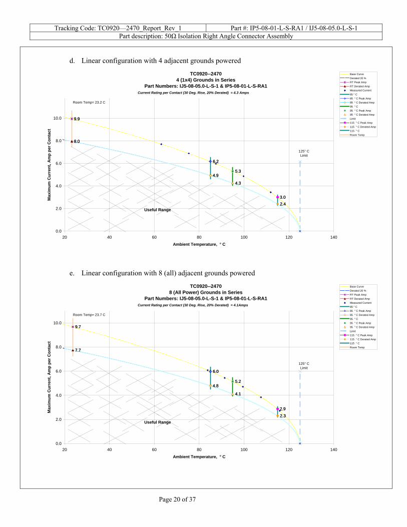
d. Linear configuration with 4 adjacent grounds powered
TC0920--24704 (1x4) Grounds in Series
Part Numbers: IJ5-08-05.0-L-S-1 & IP5-08-01-L-S-RA1
9.99.9
8.08.0
6.26.2
4.94.95.35.3
4.34.3
3.03.02.42.4
0.0
2.0
4.0
6.0
8.0
10.0
20 40 60 80 100 120 140
Ambient Temperature, ° C
Max
imum
Cur
rent
, Am
p pe
r Con
tact
Base CurveDerated 20 %RT Peak AmpRT Derated AmpMeasured Current85 ° C85 ° C Peak Amp85 ° C Derated Amp95 ° C95 ° C Peak Amp95 ° C Derated AmpLimit115 ° C Peak Amp115 ° C Derated Amp115 ° CRoom Temp
125° CLimit
Useful Range
Room Temp= 23.2 C
Current Rating per Contact (30 Deg. Rise, 20% Derated) = 4.3 Amps
e. Linear configuration with 8 (all) adjacent grounds powered
TC0920--24708 (All Power) Grounds in Series
Part Numbers: IJ5-08-05.0-L-S-1 & IP5-08-01-L-S-RA1
9.79.7
7.77.7
6.06.0
4.84.85.25.2
4.14.1
2.92.9
2.32.3
0.0
2.0
4.0
6.0
8.0
10.0
20 40 60 80 100 120 140
Ambient Temperature, ° C
Max
imum
Cur
rent
, Am
p pe
r Con
tact
Base CurveDerated 20 %RT Peak AmpRT Derated AmpMeasured Current85 ° C85 ° C Peak Amp85 ° C Derated Amp95 ° C95 ° C Peak Amp95 ° C Derated AmpLimit115 ° C Peak Amp115 ° C Derated Amp115 ° CRoom Temp
125° CLimit
Useful Range
Room Temp= 23.7 C
Current Rating per Contact (30 Deg. Rise, 20% Derated) = 4.1Amps
Tracking Code: TC0920—2470_Report_Rev_1 Part #: IP5-08-01-L-S-RA1 / IJ5-08-05.0-L-S-1 Part description: 50Ω Isolation Right Angle Connector Assembly
Page 21 of 37
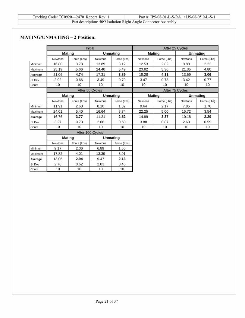
MATING/UNMATING – 2 Position:
Newtons Force (Lbs) Newtons Force (Lbs) Newtons Force (Lbs) Newtons Force (Lbs)
Minimum 16.80 3.78 13.89 3.12 12.53 2.82 9.88 2.22Maximum 25.19 5.66 24.40 5.49 23.82 5.36 21.35 4.80Average 21.06 4.74 17.31 3.89 18.28 4.11 13.59 3.06St Dev 2.92 0.66 3.49 0.79 3.47 0.78 3.42 0.77Count 10 10 10 10 10 10 10 10
Newtons Force (Lbs) Newtons Force (Lbs) Newtons Force (Lbs) Newtons Force (Lbs)
Minimum 11.91 2.68 8.10 1.82 9.64 2.17 7.85 1.76Maximum 24.01 5.40 16.64 3.74 22.25 5.00 15.72 3.54Average 16.76 3.77 11.21 2.52 14.99 3.37 10.18 2.29St Dev 3.27 0.73 2.66 0.60 3.88 0.87 2.63 0.59Count 10 10 10 10 10 10 10 10
Newtons Force (Lbs) Newtons Force (Lbs)
Minimum 9.17 2.06 6.89 1.55Maximum 17.82 4.01 13.39 3.01Average 13.06 2.94 9.47 2.13St Dev 2.76 0.62 2.03 0.46Count 10 10 10 10
After 100 Cycles
After 25 CyclesInitial
After 50 Cycles After 75 Cycles
Mating Unmating Mating Unmating
Mating Unmating
Mating Unmating
Mating Unmating
Tracking Code: TC0920—2470_Report_Rev_1 Part #: IP5-08-01-L-S-RA1 / IJ5-08-05.0-L-S-1 Part description: 50Ω Isolation Right Angle Connector Assembly
Page 22 of 37
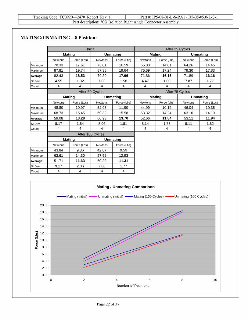
MATING/UNMATING – 8 Position:
Newtons Force (Lbs) Newtons Force (Lbs) Newtons Force (Lbs) Newtons Force (Lbs)
Minimum 78.33 17.61 73.81 16.59 65.88 14.81 64.26 14.45Maximum 87.81 19.74 87.35 19.64 76.69 17.24 79.30 17.83Average 82.43 18.53 79.89 17.96 71.86 16.16 71.89 16.16St Dev 4.55 1.02 7.03 1.58 4.47 1.00 7.87 1.77Count 4 4 4 4 4 4 4 4
Newtons Force (Lbs) Newtons Force (Lbs) Newtons Force (Lbs) Newtons Force (Lbs)
Minimum 48.80 10.97 52.95 11.90 44.99 10.12 46.04 10.35Maximum 68.73 15.45 69.32 15.58 63.32 14.24 63.10 14.19Average 59.08 13.28 60.93 13.70 52.66 11.84 53.11 11.94St Dev 8.17 1.84 8.06 1.81 8.14 1.83 8.11 1.82Count 4 4 4 4 4 4 4 4
Newtons Force (Lbs) Newtons Force (Lbs)
Minimum 43.84 9.86 42.67 9.59Maximum 63.61 14.30 57.52 12.93Average 51.71 11.63 50.33 11.31St Dev 9.17 2.06 7.88 1.77Count 4 4 4 4
After 100 Cycles
After 25 CyclesInitial
After 50 Cycles After 75 Cycles
Mating Unmating Mating Unmating
Mating Unmating
Mating Unmating
Mating Unmating
Mating / Unmating Comparison
0.00
2.00
4.00
6.00
8.00
10.00
12.00
14.00
16.00
18.00
20.00
0 2 4 6 8
Number of Positions
Forc
e (L
bs)
10
Mating (Initial) Unmating (Initial) Mating (100 Cycles) Unmating (100 Cycles)
Tracking Code: TC0920—2470_Report_Rev_1 Part #: IP5-08-01-L-S-RA1 / IJ5-08-05.0-L-S-1 Part description: 50Ω Isolation Right Angle Connector Assembly
Page 23 of 37
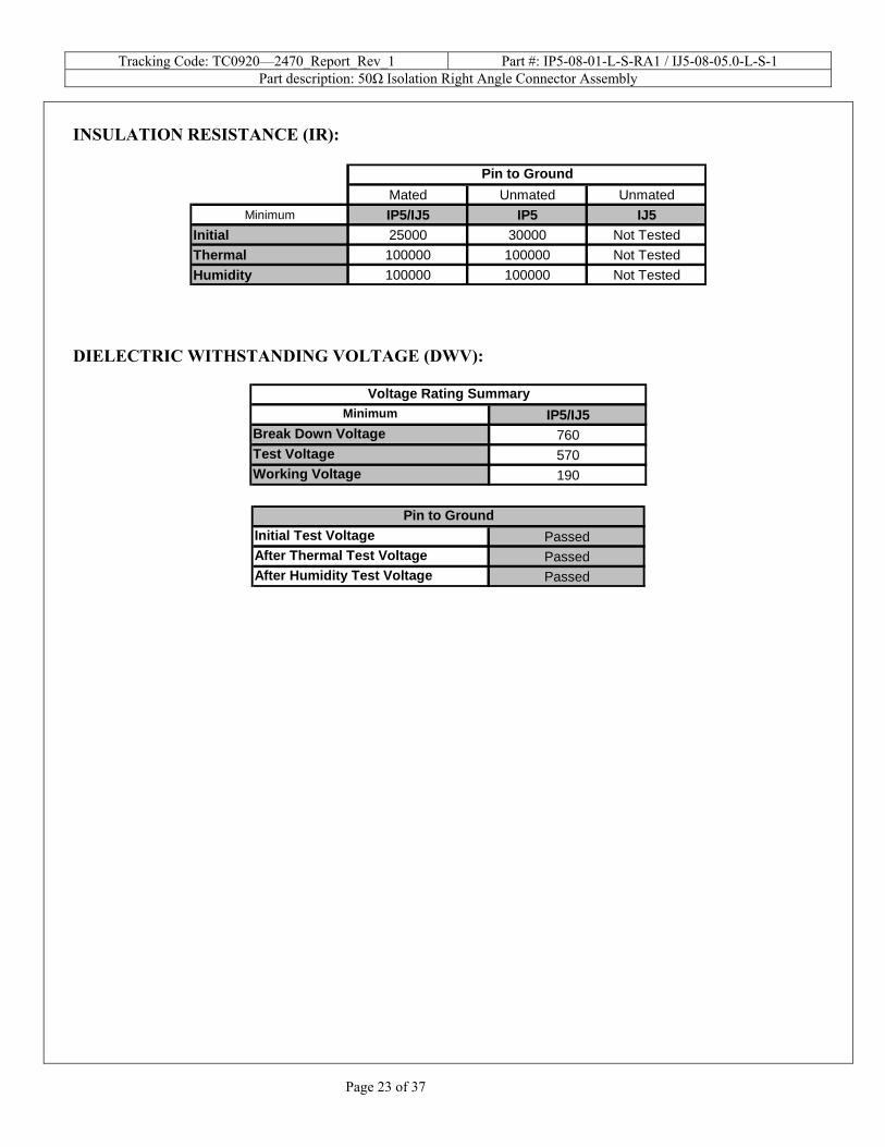
INSULATION RESISTANCE (IR):
Mated Unmated UnmatedMinimum IP5/IJ5 IP5 IJ5
Initial 25000 30000 Not TestedThermal 100000 100000 Not TestedHumidity 100000 100000 Not Tested
Pin to Ground
DIELECTRIC WITHSTANDING VOLTAGE (DWV):
IP5/IJ5760570190
Voltage Rating Summary
Break Down Voltage
Working VoltageTest Voltage
Minimum
PassedPassedPassed
Pin to GroundInitial Test VoltageAfter Thermal Test VoltageAfter Humidity Test Voltage
Tracking Code: TC0920—2470_Report_Rev_1 Part #: IP5-08-01-L-S-RA1 / IJ5-08-05.0-L-S-1 Part description: 50Ω Isolation Right Angle Connector Assembly
Page 24 of 37
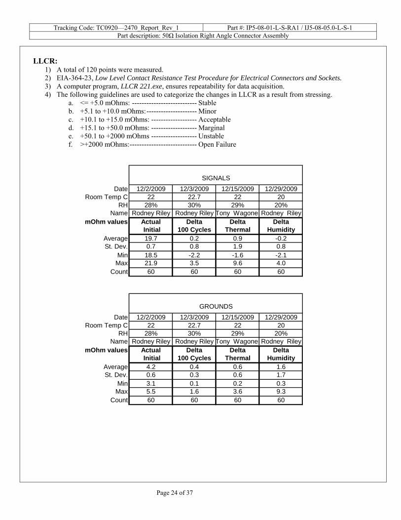
LLCR:
1) A total of 120 points were measured. 2) EIA-364-23, Low Level Contact Resistance Test Procedure for Electrical Connectors and Sockets. 3) A computer program, LLCR 221.exe, ensures repeatability for data acquisition. 4) The following guidelines are used to categorize the changes in LLCR as a result from stressing.
a. <= +5.0 mOhms: --------------------------- Stable b. +5.1 to +10.0 mOhms:--------------------- Minor c. +10.1 to +15.0 mOhms: ------------------- Acceptable d. +15.1 to +50.0 mOhms: ------------------- Marginal e. +50.1 to +2000 mOhms ------------------- Unstable f. >+2000 mOhms:---------------------------- Open Failure
Date 12/2/2009 12/3/2009 12/15/2009 12/29/2009Room Temp C 22 22.7 22 20
RH 28% 30% 29% 20%Name Rodney Riley Rodney Riley Tony Wagoner Rodney Riley
mOhm values Actual Delta Delta Delta Initial 100 Cycles Thermal Humidity
Average 19.7 0.2 0.9 -0.2St. Dev. 0.7 0.8 1.9 0.8
Min 18.5 -2.2 -1.6 -2.1Max 21.9 3.5 9.6 4.0
Count 60 60 60 60
SIGNALS
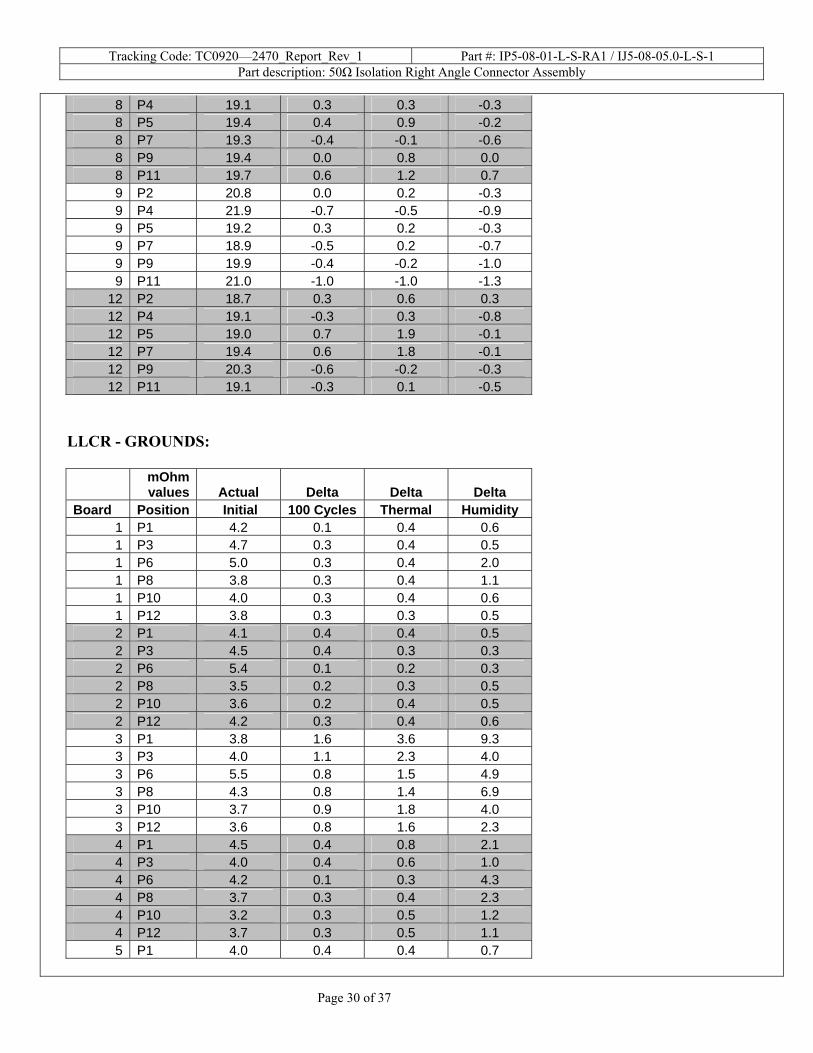
Date 12/2/2009 12/3/2009 12/15/2009 12/29/2009Room Temp C 22 22.7 22 20
RH 28% 30% 29% 20%Name Rodney Riley Rodney Riley Tony Wagoner Rodney Riley
mOhm values Actual Delta Delta Delta Initial 100 Cycles Thermal Humidity
Average 4.2 0.4 0.6 1.6St. Dev. 0.6 0.3 0.6 1.7
Min 3.1 0.1 0.2 0.3Max 5.5 1.6 3.6 9.3
Count 60 60 60 60
GROUNDS
Tracking Code: TC0920—2470_Report_Rev_1 Part #: IP5-08-01-L-S-RA1 / IJ5-08-05.0-L-S-1 Part description: 50Ω Isolation Right Angle Connector Assembly
Page 25 of 37
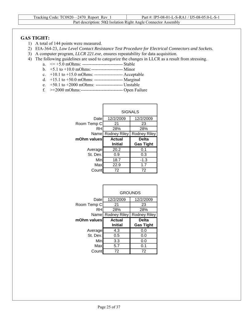
GAS TIGHT:
1) A total of 144 points were measured. 2) EIA-364-23, Low Level Contact Resistance Test Procedure for Electrical Connectors and Sockets. 3) A computer program, LLCR 221.exe, ensures repeatability for data acquisition. 4) The following guidelines are used to categorize the changes in LLCR as a result from stressing.
a. <= +5.0 mOhms: --------------------------- Stable b. +5.1 to +10.0 mOhms:--------------------- Minor c. +10.1 to +15.0 mOhms: ------------------- Acceptable d. +15.1 to +50.0 mOhms: ------------------- Marginal e. +50.1 to +2000 mOhms: ------------------ Unstable f. >+2000 mOhms:---------------------------- Open Failure
Date 12/2/2009 12/2/2009Room Temp C 21 23
RH 28% 28%Name Rodney Riley Rodney Riley
mOhm values Actual DeltaInitial Gas Tight
Average 20.2 0.1St. Dev. 0.9 0.3
Min 18.7 -1.3Max 22.9 1.7
Count 72 72
SIGNALS
Date 12/2/2009 12/2/2009Room Temp C 21 23
RH 28% 28%Name Rodney Riley Rodney Riley
mOhm values Actual DeltaInitial Gas Tight
Average 4.3 0.0St. Dev. 0.5 0.0
Min 3.3 0.0Max 5.7 0.1
Count 72 72
GROUNDS
Tracking Code: TC0920—2470_Report_Rev_1 Part #: IP5-08-01-L-S-RA1 / IJ5-08-05.0-L-S-1 Part description: 50Ω Isolation Right Angle Connector Assembly
Page 26 of 37
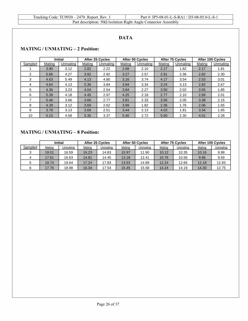
DATA
MATING / UNMATING – 2 Position:
Sample# Mating Unmating Mating Unmating Mating Unmating Mating Unmating Mating Unmating1 3.90 3.12 2.82 2.22 2.68 2.10 2.17 1.82 2.17 1.812 5.66 4.27 3.92 2.92 3.27 2.57 2.91 2.36 2.82 2.303 4.63 5.49 4.13 4.80 3.16 3.74 4.17 3.54 2.53 3.014 4.64 4.13 5.36 3.84 3.84 3.34 3.24 3.13 2.82 2.675 4.36 3.23 4.04 2.54 3.84 2.27 3.50 2.02 3.55 1.856 5.39 4.18 4.45 2.97 4.25 2.18 2.77 2.10 2.69 2.017 5.46 3.66 3.66 2.77 3.81 2.33 3.56 2.05 3.38 2.158 4.39 3.12 3.69 2.62 3.99 1.82 2.36 1.76 2.06 1.559 3.78 3.13 3.69 2.51 3.44 2.13 4.03 1.81 3.34 1.65
10 5.15 4.58 5.35 3.37 5.40 2.72 5.00 2.30 4.01 2.28
After 100 CyclesAfter 25 CyclesInitial After 75 CyclesAfter 50 Cycles
MATING / UNMATING – 8 Position:
Sample# Mating Unmating Mating Unmating Mating Unmating Mating Unmating Mating Unmating
3 19.01 16.59 16.23 14.83 10.97 11.90 10.12 10.35 10.16 9.984 17.61 16.63 14.81 14.45 13.18 12.41 10.76 10.56 9.86 9.595 19.74 19.64 17.24 17.83 13.53 14.89 12.24 12.66 12.18 12.936 17.76 18.98 16.34 17.54 15.45 15.58 14.24 14.19 14.30 12.75
After 100 CyclesAfter 25 CyclesInitial After 75 CyclesAfter 50 Cycles
Tracking Code: TC0920—2470_Report_Rev_1 Part #: IP5-08-01-L-S-RA1 / IJ5-08-05.0-L-S-1 Part description: 50Ω Isolation Right Angle Connector Assembly
Page 27 of 37
INSULATION RESISTANCE (IR):
Initial Insulation Resistance
Measured In Meg Ohms
Matedx x
Sample# IP5/IJ5 IP5 IJ51 40,000 50,0002 25,000 30,000
UnmatedPin to Ground
Measured In Meg OhmsThermal Insulation Resistance
Matedx x
Sample# IP5/IJ5 IP5 IJ51 100000 1000002 100000 100000
Pin to GroundUnmated
Measured In Meg OhmsHumidity Insulation Resistance
Matedx x
Sample# IP5/IJ5 IP5 IJ51 100000 1000002 100000 100000
Pin to GroundUnmated
Tracking Code: TC0920—2470_Report_Rev_1 Part #: IP5-08-01-L-S-RA1 / IJ5-08-05.0-L-S-1 Part description: 50Ω Isolation Right Angle Connector Assembly
Page 28 of 37
DIELECTRIC WITHSTANDING VOLTAGE (DWV):
570Test Voltage=Initial DWV
MatedSample# IP5/IJ5 IP5 IJ5
1 570 5702 570 570
Pin to GroundUnmated
570Thermal Test Voltage
Test Voltage=
MatedSample# IP5/IJ5 IP5 IJ5
1 570 5702 570 570
UnmatedPin to Ground
570Humidity Test Voltage
Test Voltage=
MatedSample# IP5/IJ5 IP5 IJ5
1 570 5702 570 570
UnmatedPin to Ground
Tracking Code: TC0920—2470_Report_Rev_1 Part #: IP5-08-01-L-S-RA1 / IJ5-08-05.0-L-S-1 Part description: 50Ω Isolation Right Angle Connector Assembly
Page 29 of 37
LLCR - SIGNALS:
mOhm values Actual Delta Delta Delta
Board Position Initial 100 Cycles Thermal Humidity 1 P2 19.0 0.3 0.9 0.3 1 P4 19.9 1.0 7.9 1.0 1 P5 20.0 0.7 9.6 0.8 1 P7 20.0 0.3 0.1 -0.1 1 P9 20.2 0.5 1.2 0.3 1 P11 19.3 0.6 6.8 4.0 2 P2 19.0 0.2 0.5 -0.1 2 P4 20.4 0.9 0.5 -0.1 2 P5 19.5 0.1 0.1 -0.8 2 P7 20.0 0.5 0.5 -0.3 2 P9 19.2 0.4 -0.2 -0.5 2 P11 19.9 0.9 1.1 0.2 3 P2 19.0 0.6 0.6 0.6 3 P4 19.0 3.5 4.2 0.9 3 P5 20.6 2.8 2.0 0.1 3 P7 20.4 0.3 2.2 -0.3 3 P9 20.0 0.4 0.6 0.1 3 P11 19.7 1.1 1.1 -0.5 4 P2 19.9 -0.5 -0.4 -0.6 4 P4 19.4 -0.3 0.2 0.1 4 P5 19.3 -0.1 0.4 -0.5 4 P7 18.5 0.8 1.3 0.6 4 P9 19.3 0.8 0.9 -0.3 4 P11 19.0 0.0 0.8 -0.1 5 P2 19.8 -0.4 -0.3 -1.0 5 P4 19.7 0.2 -0.2 -0.7 5 P5 20.0 0.9 1.1 0.4 5 P7 19.8 -0.7 -0.7 -0.8 5 P9 19.9 -0.6 -0.1 -0.5 5 P11 20.9 -0.3 -0.4 -0.8 6 P2 19.9 0.6 0.2 -0.4 6 P4 19.9 -0.1 0.0 -0.6 6 P5 20.0 0.0 -0.2 -0.8 6 P7 20.1 -0.5 -0.1 -0.2 6 P9 21.0 -1.0 -0.9 -1.3 6 P11 21.3 -0.2 0.1 -0.5 7 P2 19.5 0.1 0.8 -0.5 7 P4 19.6 -0.4 0.2 0.1 7 P5 19.4 0.0 2.8 0.3 7 P7 19.9 -0.3 1.0 -0.2 7 P9 21.2 -2.2 -1.6 -2.1 7 P11 19.5 -0.7 0.0 -0.5 8 P2 19.1 1.1 0.7 -0.1
Tracking Code: TC0920—2470_Report_Rev_1 Part #: IP5-08-01-L-S-RA1 / IJ5-08-05.0-L-S-1 Part description: 50Ω Isolation Right Angle Connector Assembly
Page 30 of 37
8 P4 19.1 0.3 0.3 -0.3 8 P5 19.4 0.4 0.9 -0.2 8 P7 19.3 -0.4 -0.1 -0.6 8 P9 19.4 0.0 0.8 0.0 8 P11 19.7 0.6 1.2 0.7 9 P2 20.8 0.0 0.2 -0.3 9 P4 21.9 -0.7 -0.5 -0.9 9 P5 19.2 0.3 0.2 -0.3 9 P7 18.9 -0.5 0.2 -0.7 9 P9 19.9 -0.4 -0.2 -1.0 9 P11 21.0 -1.0 -1.0 -1.3
12 P2 18.7 0.3 0.6 0.3 12 P4 19.1 -0.3 0.3 -0.8 12 P5 19.0 0.7 1.9 -0.1 12 P7 19.4 0.6 1.8 -0.1 12 P9 20.3 -0.6 -0.2 -0.3 12 P11 19.1 -0.3 0.1 -0.5
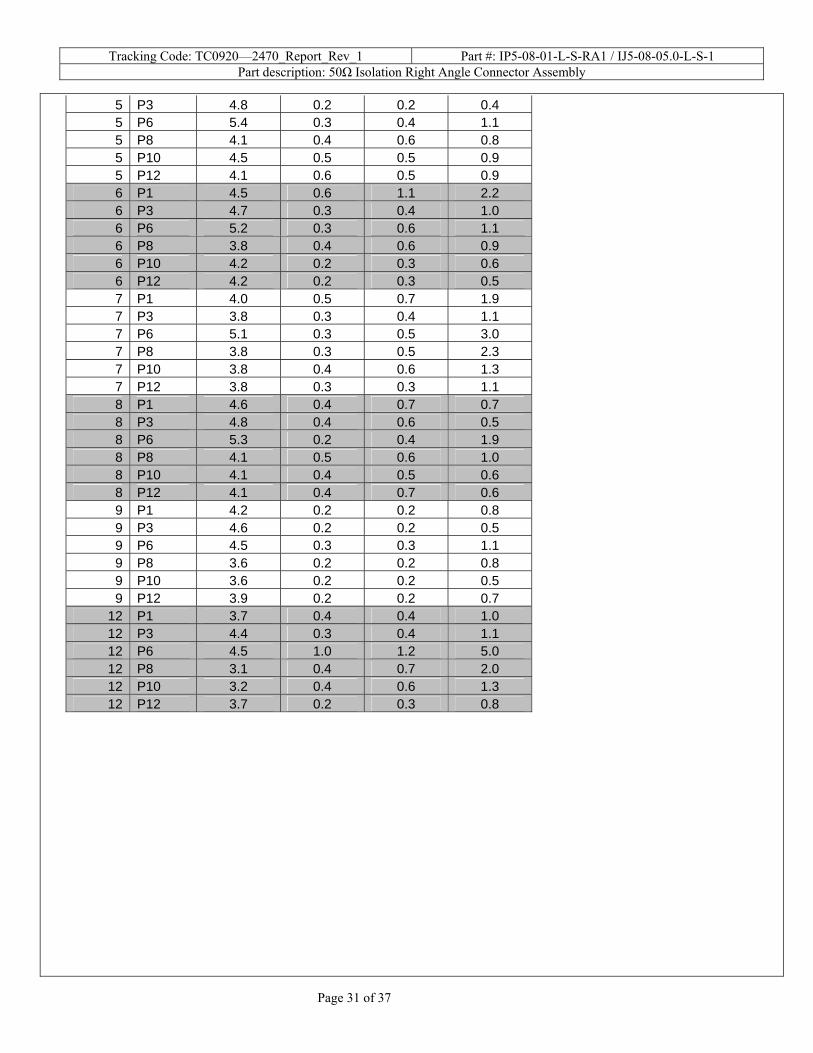
LLCR - GROUNDS:
mOhm values Actual Delta Delta Delta
Board Position Initial 100 Cycles Thermal Humidity 1 P1 4.2 0.1 0.4 0.6 1 P3 4.7 0.3 0.4 0.5 1 P6 5.0 0.3 0.4 2.0 1 P8 3.8 0.3 0.4 1.1 1 P10 4.0 0.3 0.4 0.6 1 P12 3.8 0.3 0.3 0.5 2 P1 4.1 0.4 0.4 0.5 2 P3 4.5 0.4 0.3 0.3 2 P6 5.4 0.1 0.2 0.3 2 P8 3.5 0.2 0.3 0.5 2 P10 3.6 0.2 0.4 0.5 2 P12 4.2 0.3 0.4 0.6 3 P1 3.8 1.6 3.6 9.3 3 P3 4.0 1.1 2.3 4.0 3 P6 5.5 0.8 1.5 4.9 3 P8 4.3 0.8 1.4 6.9 3 P10 3.7 0.9 1.8 4.0 3 P12 3.6 0.8 1.6 2.3 4 P1 4.5 0.4 0.8 2.1 4 P3 4.0 0.4 0.6 1.0 4 P6 4.2 0.1 0.3 4.3 4 P8 3.7 0.3 0.4 2.3 4 P10 3.2 0.3 0.5 1.2 4 P12 3.7 0.3 0.5 1.1 5 P1 4.0 0.4 0.4 0.7
Tracking Code: TC0920—2470_Report_Rev_1 Part #: IP5-08-01-L-S-RA1 / IJ5-08-05.0-L-S-1 Part description: 50Ω Isolation Right Angle Connector Assembly
Page 31 of 37
5 P3 4.8 0.2 0.2 0.4 5 P6 5.4 0.3 0.4 1.1 5 P8 4.1 0.4 0.6 0.8 5 P10 4.5 0.5 0.5 0.9 5 P12 4.1 0.6 0.5 0.9 6 P1 4.5 0.6 1.1 2.2 6 P3 4.7 0.3 0.4 1.0 6 P6 5.2 0.3 0.6 1.1 6 P8 3.8 0.4 0.6 0.9 6 P10 4.2 0.2 0.3 0.6 6 P12 4.2 0.2 0.3 0.5 7 P1 4.0 0.5 0.7 1.9 7 P3 3.8 0.3 0.4 1.1 7 P6 5.1 0.3 0.5 3.0 7 P8 3.8 0.3 0.5 2.3 7 P10 3.8 0.4 0.6 1.3 7 P12 3.8 0.3 0.3 1.1 8 P1 4.6 0.4 0.7 0.7 8 P3 4.8 0.4 0.6 0.5 8 P6 5.3 0.2 0.4 1.9 8 P8 4.1 0.5 0.6 1.0 8 P10 4.1 0.4 0.5 0.6 8 P12 4.1 0.4 0.7 0.6 9 P1 4.2 0.2 0.2 0.8 9 P3 4.6 0.2 0.2 0.5 9 P6 4.5 0.3 0.3 1.1 9 P8 3.6 0.2 0.2 0.8 9 P10 3.6 0.2 0.2 0.5 9 P12 3.9 0.2 0.2 0.7
12 P1 3.7 0.4 0.4 1.0 12 P3 4.4 0.3 0.4 1.1 12 P6 4.5 1.0 1.2 5.0 12 P8 3.1 0.4 0.7 2.0 12 P10 3.2 0.4 0.6 1.3 12 P12 3.7 0.2 0.3 0.8
Tracking Code: TC0920—2470_Report_Rev_1 Part #: IP5-08-01-L-S-RA1 / IJ5-08-05.0-L-S-1 Part description: 50Ω Isolation Right Angle Connector Assembly
Page 32 of 37
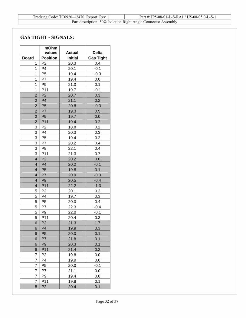
GAS TIGHT - SIGNALS:
mOhm values Actual Delta
Board Position Initial Gas Tight 1 P2 20.3 0.4 1 P4 20.1 -0.1 1 P5 19.4 -0.3 1 P7 19.4 0.0 1 P9 21.0 0.1 1 P11 19.7 -0.1 2 P2 20.7 0.3 2 P4 21.1 0.2 2 P5 20.8 -0.3 2 P7 19.3 0.5 2 P9 19.7 0.0 2 P11 19.4 0.2 3 P2 18.8 0.2 3 P4 20.3 0.3 3 P5 19.4 0.2 3 P7 20.2 0.4 3 P9 22.1 0.4 3 P11 21.3 0.7 4 P2 20.2 0.0 4 P4 20.2 -0.1 4 P5 19.8 0.1 4 P7 20.9 -0.3 4 P9 20.5 -0.4 4 P11 22.2 -1.3 5 P2 20.1 0.2 5 P4 19.7 0.3 5 P5 20.0 0.4 5 P7 22.3 -0.4 5 P9 22.0 -0.1 5 P11 20.4 0.3 6 P2 21.3 1.7 6 P4 19.9 0.3 6 P5 20.0 0.1 6 P7 21.8 0.1 6 P9 20.3 0.1 6 P11 21.4 0.2 7 P2 19.8 0.0 7 P4 19.9 0.0 7 P5 20.0 -0.1 7 P7 21.1 0.0 7 P9 19.4 0.0 7 P11 19.8 0.1 8 P2 20.4 0.1
Tracking Code: TC0920—2470_Report_Rev_1 Part #: IP5-08-01-L-S-RA1 / IJ5-08-05.0-L-S-1 Part description: 50Ω Isolation Right Angle Connector Assembly
Page 33 of 37
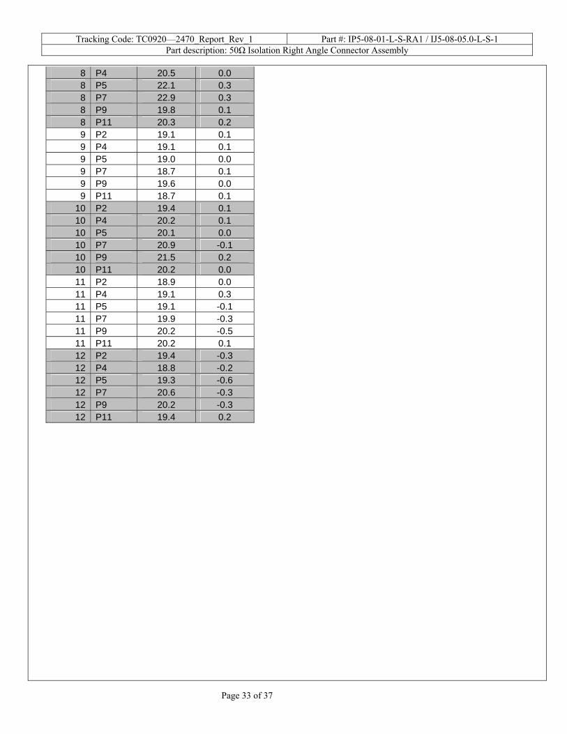
8 P4 20.5 0.0 8 P5 22.1 0.3 8 P7 22.9 0.3 8 P9 19.8 0.1 8 P11 20.3 0.2 9 P2 19.1 0.1 9 P4 19.1 0.1 9 P5 19.0 0.0 9 P7 18.7 0.1 9 P9 19.6 0.0 9 P11 18.7 0.1
10 P2 19.4 0.1 10 P4 20.2 0.1 10 P5 20.1 0.0 10 P7 20.9 -0.1 10 P9 21.5 0.2 10 P11 20.2 0.0 11 P2 18.9 0.0 11 P4 19.1 0.3 11 P5 19.1 -0.1 11 P7 19.9 -0.3 11 P9 20.2 -0.5 11 P11 20.2 0.1 12 P2 19.4 -0.3 12 P4 18.8 -0.2 12 P5 19.3 -0.6 12 P7 20.6 -0.3 12 P9 20.2 -0.3 12 P11 19.4 0.2
Tracking Code: TC0920—2470_Report_Rev_1 Part #: IP5-08-01-L-S-RA1 / IJ5-08-05.0-L-S-1 Part description: 50Ω Isolation Right Angle Connector Assembly
Page 34 of 37
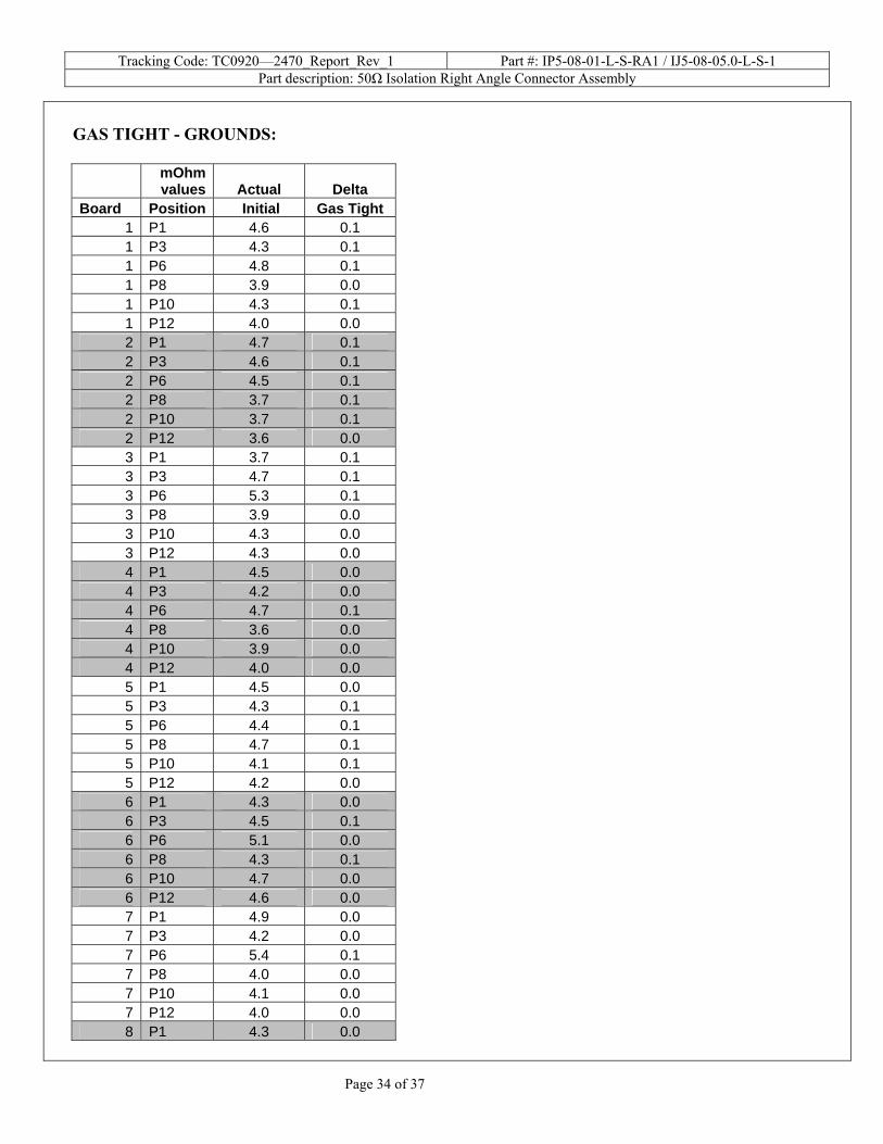
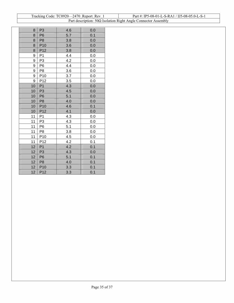
GAS TIGHT - GROUNDS:
mOhm values Actual Delta
Board Position Initial Gas Tight 1 P1 4.6 0.1 1 P3 4.3 0.1 1 P6 4.8 0.1 1 P8 3.9 0.0 1 P10 4.3 0.1 1 P12 4.0 0.0 2 P1 4.7 0.1 2 P3 4.6 0.1 2 P6 4.5 0.1 2 P8 3.7 0.1 2 P10 3.7 0.1 2 P12 3.6 0.0 3 P1 3.7 0.1 3 P3 4.7 0.1 3 P6 5.3 0.1 3 P8 3.9 0.0 3 P10 4.3 0.0 3 P12 4.3 0.0 4 P1 4.5 0.0 4 P3 4.2 0.0 4 P6 4.7 0.1 4 P8 3.6 0.0 4 P10 3.9 0.0 4 P12 4.0 0.0 5 P1 4.5 0.0 5 P3 4.3 0.1 5 P6 4.4 0.1 5 P8 4.7 0.1 5 P10 4.1 0.1 5 P12 4.2 0.0 6 P1 4.3 0.0 6 P3 4.5 0.1 6 P6 5.1 0.0 6 P8 4.3 0.1 6 P10 4.7 0.0 6 P12 4.6 0.0 7 P1 4.9 0.0 7 P3 4.2 0.0 7 P6 5.4 0.1 7 P8 4.0 0.0 7 P10 4.1 0.0 7 P12 4.0 0.0 8 P1 4.3 0.0
Tracking Code: TC0920—2470_Report_Rev_1 Part #: IP5-08-01-L-S-RA1 / IJ5-08-05.0-L-S-1 Part description: 50Ω Isolation Right Angle Connector Assembly
Page 35 of 37
8 P3 4.6 0.0 8 P6 5.7 0.1 8 P8 3.8 0.0 8 P10 3.6 0.0 8 P12 3.8 0.0 9 P1 4.4 0.0 9 P3 4.2 0.0 9 P6 4.4 0.0 9 P8 3.6 0.0 9 P10 3.7 0.0 9 P12 3.5 0.0
10 P1 4.3 0.0 10 P3 4.5 0.0 10 P6 5.1 0.0 10 P8 4.0 0.0 10 P10 4.6 0.1 10 P12 4.1 0.0 11 P1 4.3 0.0 11 P3 4.3 0.0 11 P6 5.1 0.0 11 P8 3.8 0.0 11 P10 4.5 0.0 11 P12 4.2 0.1 12 P1 4.2 0.1 12 P3 4.3 0.0 12 P6 5.1 0.1 12 P8 4.0 0.1 12 P10 3.3 0.1 12 P12 3.3 0.1
Tracking Code: TC0920—2470_Report_Rev_1 Part #: IP5-08-01-L-S-RA1 / IJ5-08-05.0-L-S-1 Part description: 50Ω Isolation Right Angle Connector Assembly
Page 36 of 37
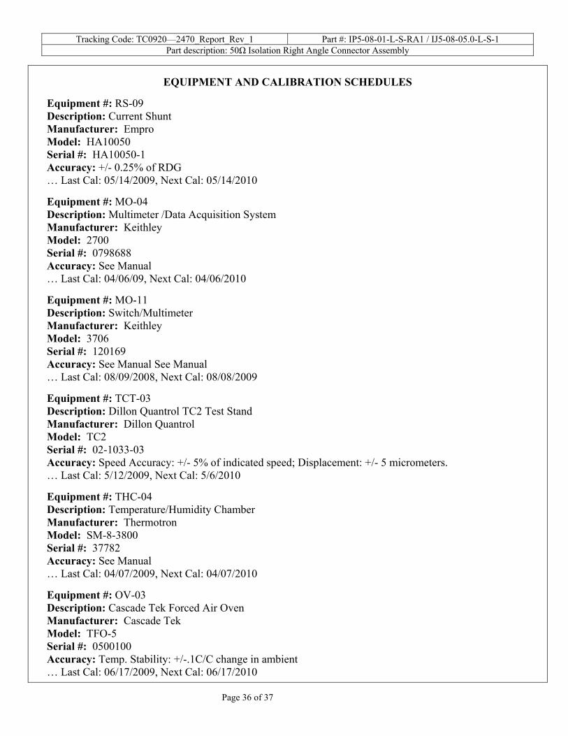
EQUIPMENT AND CALIBRATION SCHEDULES
Equipment #: RS-09 Description: Current Shunt Manufacturer: Empro Model: HA10050 Serial #: HA10050-1 Accuracy: +/- 0.25% of RDG … Last Cal: 05/14/2009, Next Cal: 05/14/2010 Equipment #: MO-04 Description: Multimeter /Data Acquisition System Manufacturer: Keithley Model: 2700 Serial #: 0798688 Accuracy: See Manual … Last Cal: 04/06/09, Next Cal: 04/06/2010 Equipment #: MO-11 Description: Switch/Multimeter Manufacturer: Keithley Model: 3706 Serial #: 120169 Accuracy: See Manual See Manual … Last Cal: 08/09/2008, Next Cal: 08/08/2009 Equipment #: TCT-03 Description: Dillon Quantrol TC2 Test Stand Manufacturer: Dillon Quantrol Model: TC2 Serial #: 02-1033-03 Accuracy: Speed Accuracy: +/- 5% of indicated speed; Displacement: +/- 5 micrometers. … Last Cal: 5/12/2009, Next Cal: 5/6/2010 Equipment #: THC-04 Description: Temperature/Humidity Chamber Manufacturer: Thermotron Model: SM-8-3800 Serial #: 37782 Accuracy: See Manual … Last Cal: 04/07/2009, Next Cal: 04/07/2010 Equipment #: OV-03 Description: Cascade Tek Forced Air Oven Manufacturer: Cascade Tek Model: TFO-5 Serial #: 0500100 Accuracy: Temp. Stability: +/-.1C/C change in ambient … Last Cal: 06/17/2009, Next Cal: 06/17/2010
Tracking Code: TC0920—2470_Report_Rev_1 Part #: IP5-08-01-L-S-RA1 / IJ5-08-05.0-L-S-1 Part description: 50Ω Isolation Right Angle Connector Assembly
Page 37 of 37
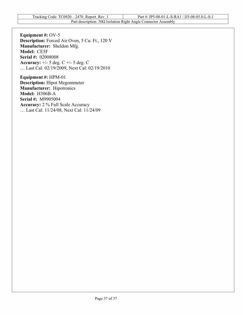
Equipment #: OV-5 Description: Forced Air Oven, 5 Cu. Ft., 120 V Manufacturer: Sheldon Mfg. Model: CE5F Serial #: 02008008 Accuracy: +/- 5 deg. C +/- 5 deg. C … Last Cal: 02/19/2009, Next Cal: 02/19/2010 Equipment #: HPM-01 Description: Hipot Megommeter Manufacturer: Hipotronics Model: H306B-A Serial #: M9905004 Accuracy: 2 % Full Scale Accuracy … Last Cal: 11/24/08, Next Cal: 11/24/09