DESIGN, PERFORMANCE, MATERIAL AND … · project: “procurement and installation of the building...
83
page 1 out of 83 TITLE OF THE TENDER: “PROCUREMENT AND INSTALLATION OF THE BUILDING AUTOMATION AND CONTROL SYSTEM (BACS) IN THE THESSALONIKI METRO EXTENSION TO KALAMARIA” RFP-327/17, Α.Σ. 48966 DESIGN, PERFORMANCE, MATERIAL AND WORKMANSHIP SPECIFICATIONS
Transcript of DESIGN, PERFORMANCE, MATERIAL AND … · project: “procurement and installation of the building...

page 1 out of 83
TITLE OF THE TENDER: “PROCUREMENT AND INSTALLATION OF THE
BUILDING AUTOMATION AND CONTROL SYSTEM
(BACS) IN THE THESSALONIKI METRO EXTENSION
TO KALAMARIA”
RFP-327/17, Α.Σ. 48966
DESIGN, PERFORMANCE, MATERIAL AND
WORKMANSHIP SPECIFICATIONS
PROJECT: “PROCUREMENT AND
INSTALLATION OF THE BUILDING
AUTOMATION AND CONTROL
SYSTEM (BACS) IN THE
THESSALONIKI METRO
EXTENSION TO KALAMARIA”
DESIGN, PERFORMANCE MATERIAL
AND WORKMANSHIP SPECIFICATIONS
RFP-327/17
Α.Σ. 48966
page 2 out of 83
CONTENTS: 1 INTRODUCTION ................................................................................................................... 4
1.1 General – Extension to Kalamaria............................................................................. 4 1.2 General – Building Automation and Control System (BACS) ............................... 4 1.3 Purpose of this specification ...................................................................................... 5 1.4 Specification Scope ...................................................................................................... 6
2 DEFINITIONS AND ABBREVIATIONS ................................................................................ 7 3 STANDARDS AND REGULATIONS ..................................................................................... 9 4 ENVIRONMENTAL CONDITIONS ...................................................................................... 11
Outdoor air conditions .......................................................................................................... 11 Indoor air conditions ............................................................................................................. 11
5 DESIGN RESPONSIBILITY ................................................................................................ 13 6 BACS SYSTEM ARCHITECTURE ....................................................................................... 15
6.1 Architecture of the Tunnel Ventilation and HVAC Systems and E&M Systems 15 6.2 Required works to the already operating BACS system...................................... 19 6.3 Interface with the Fire Detection System (FDS) .................................................. 20 6.4 Interface with the Automatic Fare Collection System (AFC) .............................. 21 6.5 BACS Control interface with the OCC/ECR ............................................................ 21
7 BACS SYSTEM REQUIREMENTS ...................................................................................... 23 7.1 General ........................................................................................................................ 23 7.2 Operation requirements ............................................................................................ 24 7.3 General principles of control and monitoring ........................................................ 27 It is pointed out that activation of a fire-scenario should entail the opening of the
respective gates of the Automatic Fare Collection in the affected station(s) for smooth evacuation of the station(s). ................................................................................. 31 7.4 Communication Network .......................................................................................... 32 7.5 Programmable Logic Controller (PLC) .................................................................... 33 7.6 BACS Software ........................................................................................................... 34 7.7 Fireman Box (FB) ....................................................................................................... 36
8 BACS and HUMAN-MACHINE INTERFACE (HMI) REQUIREMENTS ............................ 37 8.1 OCC/ECR and SMR Operator Workstation (Operator Terminals) ...................... 37 8.2 User Interface Software Requirements .................................................................. 38 8.3 System Access Security ............................................................................................ 39 8.4 System Integrity ........................................................................................................ 39 8.5 Alarms and Events ..................................................................................................... 39 8.6 Workstation Screen Key Functions ......................................................................... 41 8.7 BACS Tools .................................................................................................................. 44 8.8 Printers ........................................................................................................................ 47 8.9 Equipment and finishes ............................................................................................. 47
PROJECT: “PROCUREMENT AND
INSTALLATION OF THE BUILDING
AUTOMATION AND CONTROL
SYSTEM (BACS) IN THE
THESSALONIKI METRO
EXTENSION TO KALAMARIA”
DESIGN, PERFORMANCE MATERIAL
AND WORKMANSHIP SPECIFICATIONS
RFP-327/17
Α.Σ. 48966
page 3 out of 83
9 DOCUMENTATION .............................................................................................................. 49 9.1 General ........................................................................................................................ 49 9.2 Detailed Final Design (DFD1) .................................................................................. 49 9.3 Detailed Final Design (DFD2) .................................................................................. 49 9.4 Other documentation ................................................................................................ 50 9.5 Manuals........................................................................................................................ 51
10 TRAINING REQUIREMENTS .............................................................................................. 52 10.1 General ........................................................................................................................ 52 Training on the provision of Technical services and support ...................................................... 53 10.2 Operation training ...................................................................................................... 53
11 SYSTEM TESTS AND INSPECTIONs ................................................................................ 54 11.1 Factory Acceptance Test (FAT) ................................................................................ 55 11.2 Start-up Testing and Commissioning ..................................................................... 55 11.3 Site Acceptance Test (SAT) ...................................................................................... 56 11.4 System Integration Tests (SIT) ............................................................................... 56
12 RELIABILITY, AVAILABILITY, MAINTAINABILITY AND SAFETY (RAMS) ................... 57 12.1 Availability Analysis ................................................................................................... 57 12.2 Protection against internal failures ......................................................................... 57 12.3 Protection against internal mutual perturbations ................................................. 57 12.4 Protection against external perturbations ............................................................. 58 12.5 Safety Assessments ................................................................................................... 58
13 QUALITY ASSURANCE ....................................................................................................... 59 14 SPARE PARTS, SPECIAL TOOLS AND TECHNICAL SUPPORT ...................................... 60
14.1 Parts list and Spare Parts list ................................................................................... 60 14.2 Special Tools and Test equipment .......................................................................... 61
APPENDIX A – NEW TUNNEL AND STATION VENTILATION SYSTEMS I/O POINT LIST 62 APPENDIX B – HVAC AND E&M SYSTEMS EQUIPMENT LIST OF NEW
TUNNELS/STATIONS ................................................................................................................. 75 APPENDIX C – FDS INTERFACE TO THE HVAC SYSTEMS OF THE NEW STATIONS – I/O
POINT LIST ................................................................................................................................. 80 APPENDIX d – AUTOMATIC FARE COLLeCTION SYSTEM INTERFACE TO THE BACS
SYSTEM – I/O POINT LIST ....................................................................................................... 82
PROJECT: “PROCUREMENT AND
INSTALLATION OF THE BUILDING
AUTOMATION AND CONTROL
SYSTEM (BACS) IN THE
THESSALONIKI METRO
EXTENSION TO KALAMARIA”
DESIGN, PERFORMANCE MATERIAL
AND WORKMANSHIP SPECIFICATIONS
RFP-327/17
Α.Σ. 48966
page 4 out of 83
1 INTRODUCTION
1.1 General – Extension to Kalamaria
The project of the THESSALONIKI METRO Extension to Kalamaria consists in an underground line, approximately 4.77km long, that extends as an independent branch from PATRIKIOU Station of the Base Project up to MIKRA Station. The Project includes two single-track tunnels, 5 new Stations (Nomarchia, Kalamaria, Aretsou, Nea Krini, Mikra), 3 shafts (Kritis & Pontou Shafts and Terminal Shaft), 3 railway crossovers and two tunnels‟ pumping stations at minimum height locations along the longitudinal profile of the tunnel.
1.2 General – Building Automation and Control System (BACS)
The Building Automation and Control System is a system that controls – at local and central level – certain Electromechanical Systems of the THESSALONIKI METRO (tunnel ventilation, ventilation-air/conditioning (HVAC), lifts, escalators, fire fighting, lighting, etc.) while it is connected – in term of operation – with other E/M systems (fire detection, safety control system, platform screen doors, etc.). One of BACS‟ main operations is the activation of response and smoke extraction scenarios in case of fire in stations or tunnels. The BACS system, to be installed in the system in the framework of the Base Project is described in summary below. The Base Project consists in 13 stations and one Depot in the area of Pylea that also includes the Operation Control Centre (OCC). The necessary BACS equipment at central level is to be installed in the Pylea Depot, while each one of the 13 stations and the shafts of the line will accommodate items of the BACS equipment, at a local level. For safety and redundancy reasons, additional items of equipment will be installed in the Emergency Control Room (ECR) located in a building other than the OCC within Pylea Depot. This Room shall control the entire equipment at a central level, in case of complete failure of the entire OCC. It is stressed that the BACS equipment of the Base Project shall include two sub-systems: one system shall survey and control the tunnel ventilation systems, HVAC and other E/M systems in stations, shafts and tunnels that accommodate items of equipment at local and central (OCC) level, while the other system shall activate the scenarios in case of emergencies at Safety Integration Level – SIL 2. The Contractor of this Contract shall install all necessary equipment in the new stations and shafts along the extension to Kalamaria and shall perform all necessary upgrades/modifications/additions to the BACS equipment destined to be installed (in the OCC, the ECR, in stations and everywhere else it is required) in order to control and monitor all new stations and shafts along the extension. It is pointed out than under normal conditions, the BACS is centrally operated from the OCC. The ECR in activated only when the OCC in unable – for any reason whatsoever (e.g., fire, terrorist activities, etc.)- to support the operation of the entire Metro network; in than case, all functions (control of trains, power, stations, systems, etc.) are transferred to the ECR. However, when the central BACS systems in the OCC fails, all control and
PROJECT: “PROCUREMENT AND
INSTALLATION OF THE BUILDING
AUTOMATION AND CONTROL
SYSTEM (BACS) IN THE
THESSALONIKI METRO
EXTENSION TO KALAMARIA”
DESIGN, PERFORMANCE MATERIAL
AND WORKMANSHIP SPECIFICATIONS
RFP-327/17
Α.Σ. 48966
page 5 out of 83
supervision is transferred to a local station level, i.e., control from the Station Master Room (SMR). Given that the BACS equipment for the Base Project has not yet been installed, if this equipment or its architecture is amended by the new equipment, all functional requirements remain valid and must be fulfilled by the BACS system to be installed on the extension to Kalamaria. A detailed description of the BACS system for the Base Project is attached in Appendix E.
1.3 Purpose of this specification
The scope of this Project includes the supply, installation, modifications/upgrading, testing and commissioning of a Building Automation and Control System (BACS), which shall monitor and control the electromechanical systems installed in the buildings within the Stations, ventilation shafts, and tunnels of the Extension to Kalamaria at local level from the SMR room in each Station as well as centrally from the Operation Control Centre (OCC) at Syntagma and the Emergency Control Room (ECR) at Pylea Depot.
The scope of this Project shall include all necessary upgrading, modifications – to the extent required - to the existing BACS systems destined to be installed in the Base Project.
For the sake of facilitation and brevity, the BACS systems to be installed in the Base Project shall be referred to as “Base Project BACS system”.
Finally, it is stressed that, for safety reasons, the installation of the new BACS system and final commissioning shall be effected without interrupting the operation of Base Project BACS system both locally as well in the OCC.
The Project shall also include the design, construction, supply and commissioning of the Fireman Boxes in each Station, as well the design, construction, supply and wiring of the PLC Panels.
This Technical Specification shall be read in conjunction with the other tender documents and specifically the Conditions of Contract, the Technical Description and the General Specifications.
The Contractor shall take into consideration the available information to be provided by Attiko Metro S.A, or by other involved Contractors through AM, which shall include information on:
The Base Project BACS system constructed by the Base Project Contractor
Cooperating systems and subsystems on the extension to Kalamaria, such as Tunnel Ventilation, HVAC, Lifts, Escalators, Fire fighting valve, Lighting, Pumping Stations, Fire detection, as well as on all directly or indirectly affected E/M systems constructed be the Contractor of the main contract for Kalamaria extension.
Cooperating systems and subsystems on the extension to Kalamaria which are not included in the scope of the main contract, but which are implemented by other contractors, such as the Fare Collection System – Gates system, the Digital Transmission System (DTS) and the Safety Management Systems (SMS).
PROJECT: “PROCUREMENT AND
INSTALLATION OF THE BUILDING
AUTOMATION AND CONTROL
SYSTEM (BACS) IN THE
THESSALONIKI METRO
EXTENSION TO KALAMARIA”
DESIGN, PERFORMANCE MATERIAL
AND WORKMANSHIP SPECIFICATIONS
RFP-327/17
Α.Σ. 48966
page 6 out of 83
DFDs and operating principles of the central and local BACS systems in the Bse Project, especially in the OCC and the ECR.
The information contained in this specification may not cover at a DFD level all the design criteria, such as communication protocol, Local Area Network (LAN) configuration, software development, hardware/software integration, mapping configuration, PLCs interfacing requirements, graphics displays, etc. The Contractor shall settle the above after the provision of all information data and Detailed Final Designs for the cooperating systems on the extension to Kalamaria and the Base Project BACS system, which shall be subject to AM‟s approval.
1.4 Specification Scope
This Technical Specification covers the principles and certain essential requirements for the design, development, supply, factory testing, shipment, delivery to site, installation, site testing, commissioning, start of commercial operation as well as Spare Parts, Special tools and Technical Support for the maintenance period of the system-wide BACS system for which the contractor shall provide as a minimum the following services:
Requirements analysis and development of comprehensive Functional Design of the Technical Design Specifications for the entire Base Project and the extension to Kalamaria
interface coordination with other systems;
Preparation of the Plan for System implementation and development;
Hardware and software design;
Hardware and software manufacturing;
Hardware and software factory acceptance test;
Delivery to the site;
Site installation (including control and monitoring system hardware, software and the LAN cabling with all the necessary components);
Commissioning
Site Acceptance test (SAT);
System Integration test (SIT);
Trial run assistance and system handover;
Delivery of documentation, drawings, test reports, etc;
Certification;
Training.
PROJECT: “PROCUREMENT AND
INSTALLATION OF THE BUILDING
AUTOMATION AND CONTROL
SYSTEM (BACS) IN THE
THESSALONIKI METRO
EXTENSION TO KALAMARIA”
DESIGN, PERFORMANCE MATERIAL
AND WORKMANSHIP SPECIFICATIONS
RFP-327/17
Α.Σ. 48966
page 7 out of 83
2 DEFINITIONS AND ABBREVIATIONS
Definitions and abbreviations used in this document are as follows:
A/C - Air Conditioning ACU - Air Conditioning Unit AF - Air Filter AM - ATTIKO METRO ATP - Automatic Train Protection ATS - Automatic Train Supervision ATO - Automatic Train Operation BACS - Building Automation and Control System BMS - Building Management System BSF - Blast Shaft Fan CP - Communication Processor CPU - Central Processing Unit CCR - Central Control Room DC - Direct current (denoting the 750 V DC traction power ) DFD - Detailed Final Design DPS - Differential Pressure Switch DP - Decentralised Periphery EBB - Earthing Bus Bar ECS - Environmental Control System E/E/PE - Electrical/Electronic/Programmable Electronic system EIXL - Electronic Interlocking ELOT - Greek Organisation for Standardisation EMC - Electromagnetic Compatibility EMI - Electromagnetic Interference ESC - Escalator EXF - Exhaust Fan FAP - Fire Alarm Panel FAM - Fire Alarm Management FAT - Factory Acceptance Test FB - Fireman Box FD - Fire Damper FDTM - Fire Damper with Thermal mechanism FDETM- Fire Damper with Electrical / Thermal mechanism FDS - Fire Detection System FO - Fibre Optic GFD - General Final Design HMI - Human Machine Interface HP - Heat Pump HVAC - Heating, Ventilation and Air Conditioning I/O - Input / Output INV - Frequency Converter / Inverter JF - Jet Fan LAN - Local Area Network
PROJECT: “PROCUREMENT AND
INSTALLATION OF THE BUILDING
AUTOMATION AND CONTROL
SYSTEM (BACS) IN THE
THESSALONIKI METRO
EXTENSION TO KALAMARIA”
DESIGN, PERFORMANCE MATERIAL
AND WORKMANSHIP SPECIFICATIONS
RFP-327/17
Α.Σ. 48966
page 8 out of 83
LAS - Lighting and Auxiliary Power Substation LED - Light Emitting Diode MCC - Motor Control Centre MFD - Motorized Fire Damper MOD - Motorised Damper MPI - Multi-Point Interface MSS - Material Submission Specifications MTBF - Mean Time Between Failures MTTR - Minimum Time to Repair OCC - Operations Control Centre OPC - Open Connectivity via Open Standards OLM - Optical Link Module UPE/OTE - Over Track Exhaust PLC - Programmable Logic Controller PPC - Public Power Corporation PPS - Pumps RAID - Redundant Array of Independent Disks RAMS - Reliability, Availability, Maintainability and Safety RC - Remote control RM - Remote monitoring RSD - Roller Shutter Door RS - Rectifier Substation SAF - Supply Air Fan SAT - Site Acceptance Test SIT - System Integration Test SWB - Electrical Switchboard SIL - Safety Integrity Level SPS - Staircase Pressurisation System SMR - Station Master Room SSL - Secure Socket Layer UPE - Under Platform Exhaust Air System UPS - Uninterrupted Power Supply WAN - Wide Area Network WS - Workstation
PROJECT: “PROCUREMENT AND
INSTALLATION OF THE BUILDING
AUTOMATION AND CONTROL
SYSTEM (BACS) IN THE
THESSALONIKI METRO
EXTENSION TO KALAMARIA”
DESIGN, PERFORMANCE MATERIAL
AND WORKMANSHIP SPECIFICATIONS
RFP-327/17
Α.Σ. 48966
page 9 out of 83
3 STANDARDS AND REGULATIONS
The Contractor shall be responsible, that the proposed BACS system shall comply with the requirements set out in the following standards (the last available editions at the time of the Tender, preferably international standards approved by ELOT), but not limited with:
EN ISO 16484-1: Building Automation and control systems – Part 1: Overview and definitions
EN ISO 16484-2: Building Automation and control systems – Part 2: Hardware
EN ISO 16484-5: Building Automation and control systems – Part 5: Data communication protocol
EN ISO 16484-6: Building Automation and control systems – Part 6: Data communication Conformance testing
IEC 331: Fire resisting characteristics of electric cables.
EN 50121-1: Railway applications – Electromagnetic IEC 62236-1: compatibility – Part 1:: General
EN 50121-2: Railway applications – Electromagnetic IEC 62236-2: compatibility – Part 2:: Emission of the whole railway
system to the outside world.
EN 61000-6-2: Electromagnetic compatibility (EMC) Part 6-2: Generic standards: Immunity for industrial environments
BS 5588-4: Fire precautions in the design, construction and use of buildings - Code of practice for smoke control using pressure differentials
EN 50274: Low voltage switchgear and control gear assemblies – protection against electric shock – Protection against unintentional direct contact with hazardous live parts
EN 50122-1: Railway applications. Fixed installation - Part 1: IEC 62128-1: Protective provisions relating to electrical safety and earthing.
EN 50122-2: Railway applications. Fixed installation. Part 2: IEC 62128-2: Protective provisions against the effects of stray current caused
by DC traction systems
IEC 61131-2: Programmable controllers - Part 2: EN Equipment requirements and tests.
IEC 61508-1: Functional safety of E/E/PE safety-related systems. - Part 1: General requirements.
IEC 61508-2: Functional safety of E/E/PE safety-related systems. - Part 2: Requirements for E/E/PE safety-related systems.
IEC 61508-3: Functional safety of E/E/PE safety-related systems. Part 3: Software requirements.
PROJECT: “PROCUREMENT AND
INSTALLATION OF THE BUILDING
AUTOMATION AND CONTROL
SYSTEM (BACS) IN THE
THESSALONIKI METRO
EXTENSION TO KALAMARIA”
DESIGN, PERFORMANCE MATERIAL
AND WORKMANSHIP SPECIFICATIONS
RFP-327/17
Α.Σ. 48966
page 10 out of 83
IEC 61508-4: Functional safety of E/E/PE safety-related systems. Part 4: Definitions and abbreviations.
IEC 61508-5: Functional safety of E/E/PE safety-related systems. Part 5:Examples of methods for the determination of safety integrity levels (SIL).
EN 50126: Railway applications - Specification and demonstration of reliability, availability, maintainability and safety (RAMS).
IEC 60529: Degrees of protection provided by enclosures. IP code.
ISO 11064-1: Ergonomic design of control centres. Part 1: Principles for the design of control centres.
ISO 11064-2: Ergonomic design of control centres. Part 2: Principles for the arrangement of control suites.
ISO 9241-1: Ergonomic requirements for office work with visual display terminals (VDTs). Part 1: General introduction.
ISO 13406-2: Ergonomic requirements for work with visual displays based on flat panels. Part 2: Ergonomic requirements for flat panel displays.
ISO 9000: Quality management systems – Fundamentals and vocabulary
ISO 9001: Quality management systems – Requirements
ISO 9004: Quality management systems – Guidelines for performance improvements
ISO 10007: Quality management systems – Guidelines for configuration management.
NFPA 130 Standard for Fixed Guideway Transit and Passenger Rail Systems
Where no relevant standards exist, the use of well proven equipment may be proposed for AM approval from manufacturers with proven experience in underground Metro networks, who have manufactured similar equipment at least during the last 10 years.
Where no confirmation is given in the Specification or Material and Workmanship Specification, all details, materials, equipment and workmanship for which standards have been issued by the ELOT (Greek Organisation for Standardisation) or other International standards, the relevant specification shall be in accordance with such standards.
Where Greek Regulations or Local Ordinances affect the design or choice of plant, materials or equipment, the materials, equipment and machinery supplied shall comply with all relevant sections of such regulations.
PROJECT: “PROCUREMENT AND
INSTALLATION OF THE BUILDING
AUTOMATION AND CONTROL
SYSTEM (BACS) IN THE
THESSALONIKI METRO
EXTENSION TO KALAMARIA”
DESIGN, PERFORMANCE MATERIAL
AND WORKMANSHIP SPECIFICATIONS
RFP-327/17
Α.Σ. 48966
page 11 out of 83
4 ENVIRONMENTAL CONDITIONS
Outdoor air conditions
Outdoor dry bulb temperature 34 oC (during summer) – for underground areas 35 oC (during summer) – for areas and buildings at he surface
Outdoor winter dry bulb temperature
-5 oC (during winter)
Relative humidity (average) 60% (during summer) 80 % (during winter)
Average daily temperature variation
10 oC DB
Indoor air conditions
The maximum allowable summer temperatures and the minimum allowable winter temperatures for areas / rooms within the Metro System, as based on the designed outdoor air conditions shall be as follows:
Area Summer
temperature Winter
temperature
Concourse areas, platforms, staircases, accesses and all remaining public areas
37 oC (or +3 oC above ambient temperature)
Tunnels 37 oC (or +3 oC above ambient temperature)
Personnel Areas (Ticket Offices, SMR, Rest rooms, terminal station personnel room, Police – Security room, First Aid room, other personnel areas, guardhouses)
26 oC
20 oC
ATIMs Areas
LAS Substation (3.3/3.3)
Rectifier Substation (RS) (3.9)
Platform Screen Doors (3.23)
Cooling Facilities Room (3.7)
Tunnel Ventilation Panel Room (3.22)
Lifts plant room
Lifts Shafts
UPS Room (3.24)
Fire Fighting Room (3.18)
40 oC (or +6 oC above ambient temperature)
PROJECT: “PROCUREMENT AND
INSTALLATION OF THE BUILDING
AUTOMATION AND CONTROL
SYSTEM (BACS) IN THE
THESSALONIKI METRO
EXTENSION TO KALAMARIA”
DESIGN, PERFORMANCE MATERIAL
AND WORKMANSHIP SPECIFICATIONS
RFP-327/17
Α.Σ. 48966
page 12 out of 83
Fire Extinguishing Room (3.13)
Pumping Stations (3.5)
Storehouses (3.19)
Other Technical rooms
Central Control Room in the OCC in the Depot (see unit 15 for more information)
Constantly 25 - 26 oC humidity control 55% + 5% RH
Tunnel Recess room 40 oC (or +3 oC to the tunnel temperature given above)
PPC Room (20KV) (3.10) Natural Ventilation only
Telecommunications and Signaling Rooms (Stations – Depot)
Constantly 26 oC/ 50% RH
Battery Room (3.8) Constantly 28 oC
UPS Room (3.24)
Shops – Other Commercial areas / Recreational Areas
25 oC 20 oC
PROJECT: “PROCUREMENT AND
INSTALLATION OF THE BUILDING
AUTOMATION AND CONTROL
SYSTEM (BACS) IN THE
THESSALONIKI METRO
EXTENSION TO KALAMARIA”
DESIGN, PERFORMANCE MATERIAL
AND WORKMANSHIP SPECIFICATIONS
RFP-327/17
Α.Σ. 48966
page 13 out of 83
5 DESIGN RESPONSIBILITY
The Contractor shall be responsible for the design, procurement, installation, testing and commissioning of the BACS, as well as for the entire pertinent equipment. The approval of the design by ATTIKO METRO does not release the design responsibility of the Contractor.
The Contractor shall be responsible to take action, at his own cost, to modify, replace or adjust the BACS installations on site to meet the performance requirements as explicitly stated in the present Specifications document.
Equipment, materials and designs supplied for the BACS shall be designed and installed in accordance with the relevant European or National Standards - Regulations. Equipment to be used shall be listed and the relevant standard or specification indicated. Equipment in this context shall be taken to include both hardware and software.
All designs, material, equipment and accessories supplied under this Contract shall be to the approval of Attiko Metro.
During the implementation of the Project, AM shall deliver to the Contractor all necessary DFD documents and the Technical Descriptions of the Base Project BACS system, of every cooperating system of the main Contract for the Kalamaria extension and every cooperating system of the other contracts for the same extension.
All the requirements as outlined in this specification must be regarded as minimum.
During the first stages of the project design, the Contractor shall prepare a complete design and analysis based upon the final user (Operator) requirements and from this, he shall provide a Detailed Final Design Report (DFD-Report). This DFD-Report shall:
Be accurate and concise, with references to international standards;
Be easily understood by those people having to make use of it;
Contain sufficient information so as to provide for a complete understanding of the systems functionality;
This document shall be approved by AM before the system design commences.
In support of this, the Contractor shall implement a rigorous and traceable design change management system that allocates a unique number to each change and which as a minimum describes:
The requirement for the change;
The nature of the change;
The full impact of the change in terms of technology applied, safety, cost and programme.
The contractor shall prepare and submit Material Submission Sheets (MSS) for each individual equipment type proposed for approval by AM prior to purchase. All drawings, schedules and plans produced shall be fully consistent with the Attiko Metro Drawing Office Manual. All symbols, nomenclature and abbreviations used shall be described on the drawings.
PROJECT: “PROCUREMENT AND
INSTALLATION OF THE BUILDING
AUTOMATION AND CONTROL
SYSTEM (BACS) IN THE
THESSALONIKI METRO
EXTENSION TO KALAMARIA”
DESIGN, PERFORMANCE MATERIAL
AND WORKMANSHIP SPECIFICATIONS
RFP-327/17
Α.Σ. 48966
page 14 out of 83
All drawings, wiring and ladder diagrams etc, shall be supported by clearly presented flow charts and detailed functional and technical design specification explaining the operation of the proposed systems.
All materials shall, where applicable, comply with the fire safety standards.
All designs, materials and equipment shall continue to work correctly and safely in the presence of electromagnetic interference (EMI), if any, created by other equipment. The Contractor shall identify such sources and providing adequate screening or other remedial measures.
PROJECT: “PROCUREMENT AND
INSTALLATION OF THE BUILDING
AUTOMATION AND CONTROL
SYSTEM (BACS) IN THE
THESSALONIKI METRO
EXTENSION TO KALAMARIA”
DESIGN, PERFORMANCE MATERIAL
AND WORKMANSHIP SPECIFICATIONS
RFP-327/17
Α.Σ. 48966
page 15 out of 83
6 BACS SYSTEM ARCHITECTURE
6.1 Architecture of the Tunnel Ventilation and HVAC Systems and E&M Systems
Based on the original BACS system for the Base Project, the purpose of the BACS is to control and monitor all Tunnel Ventilation and HVAC systems, as well as the E&M systems within the Stations, shafts, tunnels and Recesses, under normal and emergency conditions. The control and monitoring shall be performed both centrally and locally from the individual/autonomous/ servers-workstations to be installed by the Contractor in the SMR in each Station.
The same basic architecture shall be implemented by the Contractor in the extension to Kalamaria, using the equipment and the features described below. The equipment in the OCC and the ECR shall remain the same original equipment and it shall be expanded / upgraded as necessary in terms of software and additional equipment, in order to accommodate the extension to Kalamaria.
The BACS shall be capable of performing real-time trending and statistical process control for some of the critical parameters. It shall provide historical data storage of update to six months.
The main components of the BACS are:
Standard and redundant server BACS system of industrial type, installed in the Operations Control Centre (OCC) and the Emergency Control Room (ECR) for normal operating conditions, as well as a parallel system installed in the OCC and the ECR, whose purpose shall be to safely (SIL2) activate the emergency scenarios;
Workstations within the OCC and the ECR, whch shall communicate with the servers, to control and monitor the installations;
PLC, PLC panel and workstation within the OCC and the ECR, for the purpose of activating and monitoring the emergency scenarios in stations and tunnels;
Industrial type workstations acting simultaneously as client/server in the each Station Master Room (SMR), capable of easy plant operation;
PLC, PLC panel and workstation within each Station Master Room, for the purpose of activating and monitoring the emergency scenarios of a specific station and its adjacent stations (N-1, N-2, N+1, N+2) and the respective tunnel sections;
PLC‟s of industrial type, housed in PLC Panels to be installed within local plant rooms close to the Fan-switchboards (SWB) and E&M systems SWB in Stations. These areas shall be determined by the Main Contractor of the Extension;
A fibre optic local area ring network (LAN) - per station - providing high speed, secure communication between the Tunnel Ventilation and HVAC Systems PLCs and E&M systems PLCs in Stations and Shafts;
Printers in the SMR of each station and in the OCC/ECR;
PROJECT: “PROCUREMENT AND
INSTALLATION OF THE BUILDING
AUTOMATION AND CONTROL
SYSTEM (BACS) IN THE
THESSALONIKI METRO
EXTENSION TO KALAMARIA”
DESIGN, PERFORMANCE MATERIAL
AND WORKMANSHIP SPECIFICATIONS
RFP-327/17
Α.Σ. 48966
page 16 out of 83
Local LAN networks Interfaces and cabling to connect (communication) the PLCs to the central fibre optic redundant high-speed communication network (WAN) for communication with the OCC/ECR.
The WAN network already installed shall serve as the communication network for the communication of the PLCs of a station “N” with the OCC/ECR based BACS servers as well as for the peer-to-peer communication between the PLCs of the station “N” with the PLCs of stations “N-1” and “N+1”.
NOTE: The WAN network and the nodes on the extension to Kalamaria do not constitute part of the scope of the BACS System Contractor, but rather the scope of an independent Contractor, whose scope shall be the installation of the digital transmission system.
The workstation in each SMR shall be connected to the station based LAN and shall allow the SMR-operator to monitor and control all the Tunnel Ventilation and HVAC Systems and E&M equipment independently from / in parallel with the OCC/ECR based BACS.
In case of a WAN communication failure or a fault of the OCC/ECR based BACS, the SMR operator shall be able to supervise and control all systems of his Station from the workstation and to execute the predetermined scenarios. In case of a fault in the workstation of a Station, its supervision and control, as well as the implementation of the predetermined scenarios shall be performed by the OCC/ECR workstations.
All PCLs to be installed shall be autonomous PLCs (not master-slave) and shall provide through the associated I/O modules the interface to the Tunnel Ventilation and HVAC switchboards as well as to Stations and Tunnels E&M equipment. These PCLs shall perform local control logic, time- and event-related operation, data management and control of the plant equipment as listed hereafter:
Shafts and Tunnels Ventilation equipment:
Blast Shaft fans (BSF), and associated equipment;
Under Platform and Over Track Exhaust fans (OTE) and associated equipment;
Supply Air Fans (SAF) and the relevant equipment;
Jet Fans (JF) in the Tunnels;
Roller Shutters (RSD);
Motorised Dampers (MOD);
Fireman box (FB);
HVAC and E&M equipment in Stations and Shafts:
Supply Air Fans for technical area (SAF-E);
Exhaust fans (EXF);
Motorised dampers (MOD);
Cooling devices, their pumps and plant;
Heat Pumps (HP);
Fan coil units (FCU);
Uninterruptible Power Supplies (UPS);
Normal and Emergency Lighting;
Pumping and drainage systems;
Hydrants, hose reel systems and deluge valves (DEV);
PROJECT: “PROCUREMENT AND
INSTALLATION OF THE BUILDING
AUTOMATION AND CONTROL
SYSTEM (BACS) IN THE
THESSALONIKI METRO
EXTENSION TO KALAMARIA”
DESIGN, PERFORMANCE MATERIAL
AND WORKMANSHIP SPECIFICATIONS
RFP-327/17
Α.Σ. 48966
page 17 out of 83
Monitoring of fire dampers;
Lifts;
Escalators; The following interfaces shall also be available:
Interface with Fire Detection Switchboards;
Interface with CCTV;
Interface with the Intrusion Detection System.
The PLCs shall be electronic devices of industrial type with a central processor unit (CPU), power supply modules and modular I/O modules.
PLC-Panels shall be designed and manufactured and installed in compliance with the Material and Workmanship Specification.
PLC-Panels of the HVAC and Tunnel Ventilation (BSF, OTE, etc.) shall be installed close to the Fan-switchboards (SWB) while PLC-Panels of the E/M systems in a place who will assigned by AM.

PROJECT: “PROCUREMENT AND
INSTALLATION OF THE BUILDING
AUTOMATION AND CONTROL
SYSTEM (BACS) IN THE
THESSALONIKI METRO
EXTENSION TO KALAMARIA”
DESIGN, PERFORMANCE MATERIAL
AND WORKMANSHIP SPECIFICATIONS
RFP-327/17
Α.Σ. 48966
page 18 out of 83
Digital Transmission System (WAN)
Fiber Optic LAN - TCP/IP
Event- Printer Laser- Printer
Printer Port
UPE-PLC E/M-PLC HVAC-PLC
BSF WEST-PLC BSF EAST-PLC RSD-PLC
SMR
Station
Typical Station
WS
FB-PLC
PROJECT: “PROCUREMENT AND
INSTALLATION OF THE BUILDING
AUTOMATION AND CONTROL
SYSTEM (BACS) IN THE
THESSALONIKI METRO
EXTENSION TO KALAMARIA”
DESIGN, PERFORMANCE MATERIAL
AND WORKMANSHIP SPECIFICATIONS
RFP-327/17
Α.Σ. 48966
page 19 out of 83
6.2 Required works to the already operating BACS system
The Base Project central BACS system is foreseen to be installed in the OCC/ECR at Plylea Depot and shall control all the Tunnel Ventilation and HVAC systems, as well as the other E/M systems (lighting switchboards, escalators, pumps, etc.), via a SCADA system under the trade name “Cimplicity” made by the company GE.
All emergency scenarios (those demanding SIL2 safety level) shall be activated and monitored from a second independent SCADA system in the OCC / ECR and also in each Station Master Room, as regards the emergency scenarios for the concerned station and its adjacent stations and tunnel sections. The Contractor shall interconnect and commission the new local and central (in OCC/ECR) equipment of the stations and tunnels of the Extension to Kalamaria with the original “Cimplicity” central control and monitoring system, as well as with original, independent SIL2 SCADA system for incorporation of the new emergency scenarios.
It is imperative to ensure the smooth migration upon commencement of the BACS system operation, without interrupting the operation of the original “Cimplicity” system and of the second original central system SIL2 SCAD for the activation of the emergency scenarios or any other piece of equipment it controls. The Contractor shall be provided with specific time “windows” during night hours (01:00 – 04:30), which shall be used for the installation and testing of BACS new software.
At local level, the Contractor shall be obliged to supply, install and commission all necessary equipment at each location (PLC server, workstation, fiber optics, etc.) for collecting all control points (I/O) and transferring same to the OCC via the WAN network. The Contractor should also secure that, at local level, the new PLCs to be installed shall communicate Peer-to-Peer with the PLCs that have already been installed, as required, in line with the designs about the Tunnel Ventilation and HVAC systems. In particular, in view of creating a BACS system for Kalamaria extension, capable of combined operation with the original Base Project BACS system and capable of communicating - at local level - with the equipment to be installed, the Contractor shall:
1. Install the new equipment (servers, workstations, PLCs, switches, cabling, etc.) and the respective new software “Cimplicity” for normal operation, as well as the new software for the emergency scenarios activation system (SIL2) in the 5 new stations, the tunnels and the three shafts of the extension, as well as everywhere required. This can be implemented by modifying / expanding the existing software, or by using other new software, fully compatible – in operational terms – with the existing software;
2. Upgrade / expand “CImplicity” software and the software that secures the SIL2 fail-safe activation at the central BACS systems in OCC / ECR, as well as install – if required – new equipment or upgrade the original equipment in the OCC/ECR, for the sake of reliable operation of the new software;
3. Implement the interfaces between the new PLCs (to be installed) of the E/M equipment on Kalamaria extension and:
PROJECT: “PROCUREMENT AND
INSTALLATION OF THE BUILDING
AUTOMATION AND CONTROL
SYSTEM (BACS) IN THE
THESSALONIKI METRO
EXTENSION TO KALAMARIA”
DESIGN, PERFORMANCE MATERIAL
AND WORKMANSHIP SPECIFICATIONS
RFP-327/17
Α.Σ. 48966
page 20 out of 83
a. the new local and central (in OCC/ECR) control and monitoring system (Cimplicity)
b. the new local and central (OCC/ECR) SIL2 system which ensures the fail-safe activation of the emergency scenarios.
4. Secure the requested functions and set up all required mimic panels and schedules so as to meet all requirements set forth in this specification;
5. Implement the Peer-to-Peer communication between the new PLCs to be installed in the stations of the extension to Kalamaria and the PLCs to be installed in the Base Project (Modicon M580 Schneider), as required, for the smooth and proper operation of the Ventilation System for Stations and Tunnels;
6. Upgrade, at the interface points between the operating stations / the stations of the extension to Kalamaria and the Base Project, the operating software related to the emergency scenarios of the Base Project, as required, both centrally and locally, in view of the comprehensive execution of the emergency scenarios and develop all necessary mimic panels in the workstations of the SMRs in the affected stations of the Base Project, as well as in the workstations in the OCC/ECR.
It is stressed that an emergency scenario shall be activated in full and shall be controlled as to its comprehensive implementation by one workstation in the OCC/ECR and, more specifically, by the workstation that activated the said scenario. The implementation of the scenario can also be monitored by the workstation located in the SMR.
In addition, an emergency scenario shall be activated in full and shall be controlled by the workstation in the SMR that activated the said scenario. The implementation of the scenario can be monitored by the OCC/ECR.
Adherence to items 1 to 6 shall result in satisfying the aforementioned requirements.
6.3 Interface with the Fire Detection System (FDS)
The Fire Detection System (FDS) located at stations and shafts shall have a hardwired interface (I/O) or Modbus protocol with the HVAC PLCs and the HVAC Switchboards – in parallel, shall transmit the fire alarms and Fire Damper (FDTM, FDETM, MFD) status signals to the BACS and shall deactivate the involved fans at a hardwire and at a software level.
The Fire Detection system shall monitor the environment in the station and the shafts to detect any potential fire hazards.
All fire alarms shall be generated automatically by smoke / heat detectors, by the flow of water within the sprinkler systems or manually by the operation of a manual break glass unit and shall be indicated on the fire alarm panel (FAP) and logged in detail within the Fire Alarm Management (FAM) system.

PROJECT: “PROCUREMENT AND
INSTALLATION OF THE BUILDING
AUTOMATION AND CONTROL
SYSTEM (BACS) IN THE
THESSALONIKI METRO
EXTENSION TO KALAMARIA”
DESIGN, PERFORMANCE MATERIAL
AND WORKMANSHIP SPECIFICATIONS
RFP-327/17
Α.Σ. 48966
page 21 out of 83
The BACS System shall collect the signals from the FDSshall display these signals in the appropriate graphic display screens and shall be responsible for their transfer in the OCC.
NOTE: The FDS is not in the scope of the BACS Contractor, but rather the scope of works of the Main Contractor for the Extension to Kalamaria and, in this framework, the BACS Contractor shall cooperate with the Main Contractor to achieve and effective and reliable interface.
6.4 Interface with the Automatic Fare Collection System (AFC)
The purpose of this interface is the automatic opening of the AFC gates in case FAP announces a fire incident in a public areas, as well as in case an emergency scenario is activated in a tunnel and in a station either through the graphic environment of the BACS system in the OCC/ECR or in the Station Master Room or through the fireman box on the wall of a station connected with the BACS for the safe and smooth evacuation of the station.
The AFC System installed in stations shall be connected (hardwired) with one of the BACS available PCLs (PLC shall be selected in the DFD phase) for the BACS system to give the relevant command to the AFC system for gates‟ opening in case of emergency.
BACS shall announce two commands for the gates to open. One command shall be given to the Gates Control Panel and the second one to the Gates Power Supply Panel, in case the first command fails.
The status of each gate shall be displayed at central level at the OCC and locally at the Station Master Room on the work stations screens of the BACS system.
NOTE: The AFC system is the scope of an independent Contractor and in the framework the BACS Contractor shall cooperate with the AFC Contractor to achieve and effective and reliable interface.
6.5 BACS Control interface with the OCC/ECR
The Tunnel Ventilation and HVAC systems PLC Controllers and the E&M systems PLC Controllers in Stations and shafts are interconnected with the central BACS at the OCC/ECR, where centralized control and monitoring is performed from the central OCC WS, via the servers and WAN network.
The workstations within the OCC shall allow the operator to monitor and control all the Tunnel Ventilation and HVAC Systems and E&M equipment remotely and execute additionally predetermined scenarios at the relevant PLCs in the event of emergencies, and execute other high-level control functions.
The OCC/ECR operator workstations shall allow the operator to modify equipment operational parameters such as set points and other controlling parameters such as equipment start and stop commands, design and change time- and event-tables.
PROJECT: “PROCUREMENT AND
INSTALLATION OF THE BUILDING
AUTOMATION AND CONTROL
SYSTEM (BACS) IN THE
THESSALONIKI METRO
EXTENSION TO KALAMARIA”
DESIGN, PERFORMANCE MATERIAL
AND WORKMANSHIP SPECIFICATIONS
RFP-327/17
Α.Σ. 48966
page 22 out of 83
Synchronisation of information between the Station based PLCs and the OCC based BACS shall take place upon initialisation, following restoration of any power loss at the station, as a result of a change to equipment status or if requested by the OCC/ECR.
PROJECT: “PROCUREMENT AND
INSTALLATION OF THE BUILDING
AUTOMATION AND CONTROL
SYSTEM (BACS) IN THE
THESSALONIKI METRO
EXTENSION TO KALAMARIA”
DESIGN, PERFORMANCE MATERIAL
AND WORKMANSHIP SPECIFICATIONS
RFP-327/17
Α.Σ. 48966
page 23 out of 83
7 BACS SYSTEM REQUIREMENTS
7.1 General
The BACS System and the two parallel subsystems to be installed by the Contractor of the Base Project is a facility, which, centrally (OCC/ECR), shall have two servers for each subsystem with redundant configuration (primary/secondary or master/backup servers and hot stand-by redundancy) and with RAID5 configuration. All information to be collected from the Base Project equipment. The Contractor of this project shall ensure that all requirements and functions are implemented by the central equipment, fully covering the Extension to Kalamaria, as well.
The Contractor shall the upgrade/modify – to the extent required - the servers of the Base Project central control and monitoring system that are to be installed for the integration of the extension to Kalamaria.
In each station, there shall be installed one Workstation acts as server/ client with RAID 5 configuration to collect, record and store the information on the same LAN network, as well as the information necessary from the tunnel ventilation system of the adjacent stations, which shall be transmitted through the WAN network and are deemed required for the control and monitoring of the fire scenarios.
This information shall be collected through the PLCs and transmitted to the SMR Workstation through the local LAN network and to the central servers through the WAN network.
The BACS shall be design with all the necessary provision and spare capacity to accommodate all the possible future extensions of the Metro.
Moreover, provision shall be made so that all control and/or monitoring points related to the emergency scenarios of the extension to Kalamaria, which shall concern the future stations, may be taken into consideration and be integrated in the software of the PLCs, in order to ensure their two-way communication with the PLCs to be installed in the future extensions excluding the obligation on the part of the Contractor of this Contract to execute any additional works. The Contractor is also obliged to provide any technical/operational information that AM may request in the future concerning the BACS system this Contractor has installed / upgraded, with the view of implementing the interfacing of the system with future extensions of Thessaloniki Metro; in view of the above, the Contractor shall be available to cooperate with any future contractor involved in the network‟s extensions.
It is imperative that when installing the new software, smooth transition has to be ensured without disrupting the existing system.
The BACS shall detect the following events
Communications failure to a single PLC;
Communications failure to multiple PLC(s);
Alarm Printer Failure (Off-line, out of paper);
Low Disk Space on any HMI system or Data Historian on the network.
PROJECT: “PROCUREMENT AND
INSTALLATION OF THE BUILDING
AUTOMATION AND CONTROL
SYSTEM (BACS) IN THE
THESSALONIKI METRO
EXTENSION TO KALAMARIA”
DESIGN, PERFORMANCE MATERIAL
AND WORKMANSHIP SPECIFICATIONS
RFP-327/17
Α.Σ. 48966
page 24 out of 83
All of the elements of the Tunnel Ventilation and HVAC Systems and E&M systems shall be designed for stand-alone operation such that the PLC control logic of the associated equipment shall be performed within the PLC, as close as possible to the equipment under control.
Equipment that is interrelated or associated such as a Fan and MOD combinations shall not be located in different PLCs.
Workstations (WS) shall be provided within the OCC/ECR and the SMR to allow the operator to monitor and control in real time the related Tunnel Ventilation and HVAC Systems and E&M systems equipment.
All BACS equipment shall be capable of continuous operation at or between the limits of environmental conditions as given in section 4 without the use of air-conditioning equipment. All equipment shall be designed to operate fully within the stated conditions. The Contractor shall provide certificates for all equipment types to be supplied stating that the equipment is able to operate under the pre-determined environmental and operational limits.
The Contractor shall be responsible for ensuring that his equipment and systems are not adversely affected by the modified environmental conditions caused by the localized heat emissions of other installed equipment.
All BACS equipment supplied shall be able to withstand power supply surges, interference and spikes caused by lightning currents and equipment, mains and traction supply surges, according to the standards (Section 3).
All the hardware supplied shall be the latest series available for use at the time of the factory tests. Replacement parts for all hardware shall be available for a minimum of 10 years after commissioning of the last, in terms of time of commissioning, station. Sufficient quantity of spare parts shall be provided (see paragraph 14.1) to ensure availability and safe and reliable operation of the system, calculation shall be based on provided and proved Mean Time Between Failures (MTBF) and Minimum Time to Repair (MTTR) values. Reliability, availability, maintainability and safety (RAMS) should be proved in compliance with standards, specified in Section 3.
All BACS the hardware installed shall contain at least 15% spare capacity for future needs and be easily expandable, if required.
All BACS hardware shall be of industrial type for heavy environmental conditions and be immune to harsh environmental factors, within the realistic range of values for industial facilities. All the units shall have a suitable IP protection rating. as recommended by the standards (Section 3). PLC-Panels installed in plant rooms shall have an IP protection rating of at least IP 54.
7.2 Operation requirements
The BACS shall be designed to meet the normal- and emergency operational and performance requirements of the tunnel ventilation, HVAC systems and E&M systems.
PROJECT: “PROCUREMENT AND
INSTALLATION OF THE BUILDING
AUTOMATION AND CONTROL
SYSTEM (BACS) IN THE
THESSALONIKI METRO
EXTENSION TO KALAMARIA”
DESIGN, PERFORMANCE MATERIAL
AND WORKMANSHIP SPECIFICATIONS
RFP-327/17
Α.Σ. 48966
page 25 out of 83
All BACS equipment items as PLCs, Workstation and Printers in the SMR shall be connected to the emergency Lighting UPS.
7.2.1 Normal operation
The tunnel Ventilation, HVAC and E&M equipment and processes shall be activate / deactivated according to pre-determined operational time- and event-tables.
Some of the HVAC equipment like A/C units, Chillers, Heat Pumps which have their own independent automatic control system shall be activated / deactivated from the BACS SMR or OCC/ECR operator.
The building services and the environmental conditions inside the station shall be maintained at acceptable levels, ensuring optimum use of the facilities under automatically operated control.
An operator within the SMR or OCC shall be able to:
View, monitor, control and modify in real time the operation and status of the equipment;
View and modify in real time the controlling parameters, set points or operating parameters of the equipment;
Intervene and change the status of the Tunnel Ventilation, HVAC and other E&M equipment;
Prepare and prints reports and logs or request historical or current reports on the status of the station and equipment;
7.2.2 Tunnel Ventilation and HVAC Systems Emergency operation
The Tunnel and station Ventilation Systems shall be used to operate as smoke exhaust systems within the station public areas and related tunnel sections as per pre-determined emergency scenario requirements.
The details of the Emergency Scenarios concerning the extension to Kalamaria shall adhere to the Specifications concerning the Tunnel Ventilation and HVAC Systems of these projects.
The Contractor shall be obliged to implement all the emergency scenarios stated above in the system software for Kalamaria extension.
The Contractor shall ensure that the emergency scenarios logic shall always be available (backed-up), so as to address an eventual PLC loss, the loss of a workstation (WS) or a server.
A Fireman Box (FB) will be installed at the concourse or street level near the station entrance of every station, easily accessible to firemen. Emergency scenarios concerning only the local station (“fire at platform level”, “fire at concourse level”, “fire on a train at track 1” and “fire on a train on track 2”) shall be easily activated by the FB.
PROJECT: “PROCUREMENT AND
INSTALLATION OF THE BUILDING
AUTOMATION AND CONTROL
SYSTEM (BACS) IN THE
THESSALONIKI METRO
EXTENSION TO KALAMARIA”
DESIGN, PERFORMANCE MATERIAL
AND WORKMANSHIP SPECIFICATIONS
RFP-327/17
Α.Σ. 48966
page 26 out of 83
In case of emergency, the local metro and / or OCC (or ECR) staff shall immediately inform the OCC operators who shall manage the incident until the arrival of the fire brigade at the concerned station.
Until the arrival of a fireman, the OCC or SMR operator shall initiate all predetermined scenarios regarding the station and the tunnel from the workstation
In case a certain scenario is selected by the wall-mounted FB, then the scenario selected by the OCC, or the ECR, or the Station Master Room operator shall be de-activated. Further scenario selections from the OCC or SMR operator are inhibited.
Once a scenario is activated, indication of the scenario and equipment status shall be indicated on the BACS workstations and at the FB and all affected switchboards (SWB).
The sequence of operation for each selector switch depending on the location is given in chapter 7.3.1.2.
The operation priority for emergency operations, starting from the highest shall be:
OCC/ECR-workstation (emergency scenarios screen selector switch in Scenario mode);
SMR-workstation (emergency scenarios screen selector switch in Scenario mode);
Local switchboard controls (selector switch in position “local emergency”);
Station FB “scenario” mode (selector switch in position “Scenario”).
This means:
The scenarios executed from the local wall-mounted FB will override the SMR – OCC/ECR workstation commands, as well as the switchboards‟ “local emergency” mode commands;
The commands executed from the switchboards in “local emergency” mode override the related Fan operation selected with the OCC/ECR and SMR workstation‟s scenarios;
The local SMR-workstation emergency scenarios screen commands will override the OCC/ECR workstation screen commands;
The BACS is to be considered as a protection system that monitors all events continuously.
Any change of state of the Tunnel Ventilation and HVAC Systems equipment shall be displayed with a complete graphic change on the operator workstations within the SMR and OCC/ECR within 1 second.
Emergency scenarios executed from the OCC/ECR, SMR or FB shall override any other normal operation.
PROJECT: “PROCUREMENT AND
INSTALLATION OF THE BUILDING
AUTOMATION AND CONTROL
SYSTEM (BACS) IN THE
THESSALONIKI METRO
EXTENSION TO KALAMARIA”
DESIGN, PERFORMANCE MATERIAL
AND WORKMANSHIP SPECIFICATIONS
RFP-327/17
Α.Σ. 48966
page 27 out of 83
The HVAC PLCs and HVAC switchboards shall have a hardwired interface (I/O) with the Fire Detection System (FDS) and shall be used to shutdown the related SAF or HVAC systems or drive other E&M equipment to a safe operation position within 1 second after receiving an alarm from the FDS.
On power loss and restoration the BACS and PLCs shall restart automatically and become fully operational within 60 seconds. The operator workstations shall restart automatically and be available to display the most current information updated completely from the PLCs within 3 minutes. The Tunnel Ventilation and HVAC Systems PLCs and E&M- PLCs on restating or cold start shall request the status of all plant.
7.3 General principles of control and monitoring
All plant shall have the ability to be operated automatically or manually.
The BACS shall normally operate the plant and equipment in accordance with predefined logic and or control strategies automatically under the operation of local sensors or timetables.
The Operators shall be able to initiate manually the control of all plant and equipment from:
a) OCC / ECR operator workstation; b) SMR operator workstation; c) Local switchboard via pushbuttons.
In manual mode all automatic control on the selected equipment shall be disabled.
On switching equipment from the Automatic to the Manual mode the equipment state shall remain unchanged. The operator shall perform all control actions after selection to the Manual mode.
Table 1 below summarises the control locations for manual operation of equipment.
Equipment Designation
Equipment use Control available
Location
Electrical switchboards
Motor Control Centre (MCC). This is the central motor starter panel for a group of fans and MODs. This panel contains the electrical protection and control gear for the equipment under control and the PLC‟s in enclosed PLC-panels with associated I/O for the Tunnel Ventilation and HVAC Systems and E&M Systems. Local control can be selected and performed from this location
2 or 3 position selector switch: Remote/Local or Remote/ Local normal/ Local emergency
Blast shafts and station plant rooms
FB Fireman Box This is a pushbutton operated back up panel that is principally used in emergency situations
2 position selector switch: Remote / Scenario
Station concourse
PROJECT: “PROCUREMENT AND
INSTALLATION OF THE BUILDING
AUTOMATION AND CONTROL
SYSTEM (BACS) IN THE
THESSALONIKI METRO
EXTENSION TO KALAMARIA”
DESIGN, PERFORMANCE MATERIAL
AND WORKMANSHIP SPECIFICATIONS
RFP-327/17
Α.Σ. 48966
page 28 out of 83
SMR Operator workstation
Computer terminal with graphical interface within the station used by the operator for plant and equipment monitoring and control of the Tunnel Ventilation and HVAC Systems and E&M systems
Operation Modes: Auto / Manual
SMR
OCC Operator workstation
Computer terminal with graphical interface within the central Operations Control Centre used by the operator for plant and equipment monitoring and control and parameter adjustments of the Tunnel Ventilation and HVAC Systems and E&M systems.
Operation Modes: Auto / Manual
OCC
Table 1. Equipment Control Source
7.3.1 General control requirements
Lists containing the equipment of the extension to Kalamaria to be controlled and monitored by the BACS System, as regards Tunnel Ventilation and HVAC Systems, E/M-systems and FDS, are included as Appendices A to D of this Document. Detailed lists with all systems and details pertinent to each individual system (check points and other I/O characteristics) shall be prepared in cooperation with the main contractor of the extension. With regard to the interfacing systems, the above shall be prepared in cooperation with the other involved contractors.
Especially, regarding Tunnel Ventilation, which constitutes a critical system for the passengers‟ safety, the operation of fans under normal and emergency conditions is described here below in summary.
As regards the remaining E/M Systems, which are not automated, apart from the surveillance of the control points indicated in the aforementioned lists, their operation hours must also be recorded.
7.3.1.1 Normal Operation of the BSF, OTE , SAF, JF and EXF fans
Hours run:
The cumulative running hours of each fan shall be recorded. On initial fan start up the fan with the lowest operating hours shall start first. After a fan running is stopped or failure of a fan, then a duty / standby rotation / changeover shall be initiated.
Duty / standby:
Should a fan be operational and subsequently fail then an equipment fault shall be raised at the BACS and the standby fan shall be started.
Fan proving:
Should a fan be operational but the flow is not proven within 10 seconds then the fan shall be stopped and the standby fan started. An alarm shall be raised at the system. This alarm will be by-passed if the fan is operating under emergency conditions.
PROJECT: “PROCUREMENT AND
INSTALLATION OF THE BUILDING
AUTOMATION AND CONTROL
SYSTEM (BACS) IN THE
THESSALONIKI METRO
EXTENSION TO KALAMARIA”
DESIGN, PERFORMANCE MATERIAL
AND WORKMANSHIP SPECIFICATIONS
RFP-327/17
Α.Σ. 48966
page 29 out of 83
Fan and damper combinations:
On request to start the fan the damper shall open. With the damper confirmed as being fully opened (all sections), the fan shall be permitted to start. Should the fan fail to start within the proving period then the fan shall be commanded to stop and the associated damper closed. A duty / standby rotation principle shall be used. An alarm shall also be raised within the system. Should the damper fail to fully open within an adjustable time period then the damper open command shall be removed, the damper commanded to close and the fan start command removed. An alarm shall be raised within the system.
Note: Under emergency operation conditions (BSF, SAF and UPE/OTE fan) the related MOD and Fans shall start simultaneously irrespective if the MOD will fully open or not and all safety interlocks (e.g. winding- bearing temperature alarms or vibration alarms) will be disabled and bypassed.
Automatic control:
Where a fan operates under automatic control (e.g. two EXF-fans on temperature control), then on achieving the first stage set point the fan with the lowest hours run shall start. On achieving the second stage set point then the standby or second fan shall start. On falling temperatures the fan with the highest cumulative hours run shall be stopped first. On reaching the second stage falling temperature alarm the first fan shall be stopped. Proper measures shall be designed to eliminate the effect of hysteresis, in order to avoid the frequent stopping / starting of the fans.
Manual control:
On selecting a fan to manual all automatic features (e.g. temperature control, time- event-tables) shall be disabled, however the stage alarms shall still be provided to the system.
Remote control:
If a fan-system selector switch at the local switchboard is selected to remote control, then no control is available from the local switchboard. The plant / equipment is then under the direct control of the Tunnel Ventilation and HVAC systems and E&M systems.
Local control:
On selecting a fan system to “local (normal)” control at the local switchboard, all automatic features (e.g. temperature control) shall be disabled, however the stage alarms shall still be provided to the BACS.
When an emergency fan system (e.g. BSF, SAF or UPE/OTE fan) is selected to “local emergency” control all safety interlocking is by-passed but alarms from these devices will still be monitored at the BACS.
Maintenance:

PROJECT: “PROCUREMENT AND
INSTALLATION OF THE BUILDING
AUTOMATION AND CONTROL
SYSTEM (BACS) IN THE
THESSALONIKI METRO
EXTENSION TO KALAMARIA”
DESIGN, PERFORMANCE MATERIAL
AND WORKMANSHIP SPECIFICATIONS
RFP-327/17
Α.Σ. 48966
page 30 out of 83
All equipment shall have the facility to be set to maintenance by means of a maintenance switch close to the fan installation location. In such mode the equipment shall be disabled and not be available for the automatic or manual or local control.
7.3.1.2 Emergency Operation of the BSF, OTE, SAF, JF fans (Control of fire scenarios)
In all cases emergency operation shall take precedence over the normal operation of the equipment.
It is required that ventilation and smoke exhaust equipment, which participate in emergency scenarios, the way they have been programmed in the PLCs of the Tunnel Ventilation and HVAC systems, should have the capability of full activation of the emergency scenario within a maximum time duration of three (3) minutes. This duration includes possible change from an existing status or an already activated emergency scenario to a new scenario, which requires operation changes in already activated components (e.g. reversing of fans). It is noted that the related equipment includes all the control and activation elements such as breakers, frequency converters etc.
In case of failure of any equipment participating in the scenario, the scenario shall be continued; an alarm shall be raised within the BACS.
An emergency operating mode is selected by means of selector switches situated within the FB, the local fan SWB or on the emergency scenarios layout of the SMR / OCC/ECR Operator WS screen.
Under all emergency operation modes all safety interlocks (e.g. winding- bearing temperature alarms or vibration alarms) for the BSF, OTE fans and JF will be bypassed and do not lead to a shut down of the related fan.
The following selector switches shall be available from the:
FB:
Remote position; Scenario position;
Fan local switchboard:
Remote position; Local normal position; Local emergency position;
SMR / OCC operator WS:
Remote position; Scenario position.
The sequence of operation for each selector switch depending on location shall be defined as follows.
PROJECT: “PROCUREMENT AND
INSTALLATION OF THE BUILDING
AUTOMATION AND CONTROL
SYSTEM (BACS) IN THE
THESSALONIKI METRO
EXTENSION TO KALAMARIA”
DESIGN, PERFORMANCE MATERIAL
AND WORKMANSHIP SPECIFICATIONS
RFP-327/17
Α.Σ. 48966
page 31 out of 83
FB scenario mode
Initiated with the FB selector switch selected to this position. All functions from the FB to the BSF, OTE fans are realized by means of hardwired connections to the local SWB. If the specific scenario requires also the energization of equipment at an adjacent shaft, this energization takes place through the network. The local SWB receive the signals from the scenario pushbuttons from the FB and initiate the predetermined fire scenario operation of the fans.
SWB Local emergency mode
Initiated with the SWB selector switch selected to this position. The PLC software logic is bypassed and all the operations from the SWB are controlled by hardwired connections. BSF and OTE fans, JF and RSD for each station and related tunnel section can be controlled from the related SWB by the use of hardwired pushbuttons, with indications provided by local lamps.
OCC / SMR Operator workstation scenario emergency operation mode
Initiated with the OCC / SMR Operator WS screen emergency scenarios selector switch selected to the scenario position.
Switchboard local normal mode
Initiated with the SWB selector switch selected to this position. The operator at the SWB can initiate operation of all fans and dampers by using the available SWB controls. The PLC is in full control of the fans and MODs, protection and interlocks of all the fans is activated by the PLC. This mode is mainly used for the maintenance.
OCC / SMR Operator workstation remote mode
The selector switch on the local SWB of the FB and OCC / ECR SMR Workstation emergency scenarios screens have to be in “remote” position. The plant is in full remote control and may be operated either manually or automatically as defined by predetermined algorithms or influenced by remote sensors. This is the normal operating state of the plant.
It is pointed out that activation of a fire-scenario should entail the opening of the respective gates of the Automatic Fare Collection in the affected station(s) for smooth evacuation of the station(s).

PROJECT: “PROCUREMENT AND
INSTALLATION OF THE BUILDING
AUTOMATION AND CONTROL
SYSTEM (BACS) IN THE
THESSALONIKI METRO
EXTENSION TO KALAMARIA”
DESIGN, PERFORMANCE MATERIAL
AND WORKMANSHIP SPECIFICATIONS
RFP-327/17
Α.Σ. 48966
page 32 out of 83
7.4 Communication Network
The Contractor shall be responsible for the design and installation of a fibre optic local area network (LAN) in a ring layout in each individual Station (including related tunnel sections and adjacent shafts) providing a secure high-speed communication system.
This LAN shall connect locally and perform the information transmission among the geographically distributed Tunnel Ventilation and HVAC system PLCs, Station and Tunnel E&M systems PLCs and the SMR located workstations.
The technology and design of the LAN shall be determined based on the requirement to connect the PLCs to the system-wide WAN that connects the stations to the OCC, and on the operation and performance criteria.
The communication between the OCC/ECR based BACS servers and the Tunnel Ventilation and HVAC Systems PLCs and Station and Tunnel E&M systems PLCs as well as the peer-to-peer communication between these PLCs of the station “N” with the PLCs of stations “N-1” and “N+1” shall be established through the system wide WAN.
To achieve real-time data acquisition performance, the time delay between the local PLCs and BACS servers should be less than 0.5secs.
Failure of communications between the station based PLCs and the BACS servers, or failure of the BACS itself shall not affect the ability of the PLCs to control the process.
Failure to one of the PLCs shall not prevent the remaining PLCs of the same LAN network from transmitting data related to the systems under their control, as well as from receiving commands both from the workstations at OCC/ECR and the workstations at the SMR.
The LAN ring shall be routed via physically separate routings to maintain the integrity under fire conditions.
The LAN shall support at least 50 connected devices (nodes) excluding repeaters and gateways.
All control and communication cables and their construction or testing methods shall be subject to approval by Attiko Metro.
All control and communication cables shall be installed by competent staff, suitably trained and supplied with all necessary plant, equipment and tools. The installation of cables shall be such as to provide an orderly formation, free from unnecessary bends and crossings that will permit the removal of any one cable without undue disturbance to adjacent cables.
All control and communication cables shall be constructed in accordance to the National or International standards (see Section 3).
The construction of control and communication cables shall be fire resistant as specified by valid standards. Low smoke and halogen free material shall be used for both insulation and sheath.
PROJECT: “PROCUREMENT AND
INSTALLATION OF THE BUILDING
AUTOMATION AND CONTROL
SYSTEM (BACS) IN THE
THESSALONIKI METRO
EXTENSION TO KALAMARIA”
DESIGN, PERFORMANCE MATERIAL
AND WORKMANSHIP SPECIFICATIONS
RFP-327/17
Α.Σ. 48966
page 33 out of 83
7.5 Programmable Logic Controller (PLC)
PLC‟s shall be electronic devices of industrial type with central processor unit (CPU), memory, communication processors (CP) and power supply modules.
PLCs shall be of the latest generation during the preparation of the Detailed Final Design (DFD) for this Project.
All the equipment, as presented in the Control & Monitoring Points List, shall be connected to the PLC-I/O modules.
Each CPU and CP shall perform internal self-diagnostics and provide an alarm indication for hardware failure.
The CPU shall be capable of detecting any failure or malfunction in any other modules and provide an alarm output.
The PLC-processors shall have status LEDs at least for:
Processor status (Running/ Standby/ Fault);
Forces (Applied/ on);
Internal battery status;
Fatal alarm;
Communications status.
The power supply requirements shall be suitable for operation at 230V AC, supplied from the station UPS system. The contractor shall identify within the tender the power consumption requirements.
The PLC will be equipped with all the I/O cards necessary for the control and monitoring of all the equipment connected to that particular panel. I/O shall be modular and capable of future expansion without disruption or change to the existing equipment.
I/O modules shall be replaceable whilst on line and without the need to power down the equipment or disconnect the field wiring. The I/O modules will interface with the field equipment via approved terminals. Field wiring shall not connect directly to the I/O module. Hard keying methods shall prevent the incorrect replacement of a module.
Within the BACS, the communications highway shall be a real time, controls communication network capable of high-speed data transport and which shall:
Be high speed, minimum 100Mb / sec;
Allow multicast of both inputs and peer-to-peer data;
Allow network access from any CP / node for viewing the network status and the uploading and downloading of programmes.
The PLCs in the Station and shaft shall communicate with the local Workstations/server via Communication Processors (CPs), which shall be connected to the local LAN network of the station. The local LAN of each station shall be connected in each station to the node of the data communication network WAN.
Via the WAN the PLCs shall as well communicate with the central OCC/ECR based BACS servers.
PROJECT: “PROCUREMENT AND
INSTALLATION OF THE BUILDING
AUTOMATION AND CONTROL
SYSTEM (BACS) IN THE
THESSALONIKI METRO
EXTENSION TO KALAMARIA”
DESIGN, PERFORMANCE MATERIAL
AND WORKMANSHIP SPECIFICATIONS
RFP-327/17
Α.Σ. 48966
page 34 out of 83
Upon detecting a LAN network failure an alarm shall be provided to warn the operator in the SMR and in the OCC/ECR of the failure in the station LAN ring network.
Each PLC shall automatically resume communications following a network recovery.
The use of Open architectures shall be maximised.
Each PLC shall have a maximum scan time of 2 ms per 1K of word. Upon completion of the functional programme, communications etc., the processor memory shall as a minimum retain 30% as spare memory capacity.
The PLCs and associated equipment shall be housed within an enclosure (PLC panel) having a degree of protection not less than IP 54. The PLC panels shall be installed next to the controlled system panels (HVAC, ventilation systems, E/M systems). Enclosure design and equipment layouts etc. shall be approved by AM before manufacture.
All equipment shall operate continuously under the demanding industrial environmental conditions, as specified in the standards, listed in the Section 3.
Aspects of Electromagnetic Compatibility shall be considered in the design and layout of equipment, as specified in the standards, listed in the Section 3.
7.6 BACS Software
The software and firmware developed and installed for the BACS shall follow the requirements of the standards, as described in Section 3 and shall adopt a structured methodology and be based around a concept of standard software tasks and modules, which are integrated to provide the functionality as required each application / location.
Within the structured software design methodology the contractor shall produce structure diagrams, data flow diagrams that detail the functionality and interface requirements.
As a minimum the following BACS software shall be supplied for each of its two subsystems:
a) System‟s software including all programs for the normal real-time operation of the BACS, containing all application programs.
b) Auxiliary programs for the modification or correction of the programs, control of the real time on-line operation , post-processing required, memory printing, memory punching and memory change.
c) Auxiliary programs for detecting, analysing and correcting errors.
d) Diagnostics to detect faults or controlling the operation of the system and/or its PLC-subsystems. The subsystems contain CPU‟s, CP‟s and the relevant secondary units.
e) Test software to check the software‟s application during the system‟s development.
PROJECT: “PROCUREMENT AND
INSTALLATION OF THE BUILDING
AUTOMATION AND CONTROL
SYSTEM (BACS) IN THE
THESSALONIKI METRO
EXTENSION TO KALAMARIA”
DESIGN, PERFORMANCE MATERIAL
AND WORKMANSHIP SPECIFICATIONS
RFP-327/17
Α.Σ. 48966
page 35 out of 83
7.6.1 Structured approach
The software shall comprise a hierarchical structure which using techniques that functionally breaks down the requirement in to a number of smaller, more manageable, comprehensible functions having well defined interfaces shall be used.
The PLC Software programming shall use industry standard programming languages, as defined by the standards, listed in the Section 3.
Where more than one programming language is used, it shall be used in a consistent manner and shall be seamlessly integrated into the PLC system to avoid confusion in understanding the application.
The organisation of the programme data, data tables and programme files within the PLC shall be structured and methodical in approach using different files for functions to allow ease of understanding. The code shall be accompanied by full comments so as it is readily understood by the personnel of AM‟s Engineering Department. All variables and parameters to be used (flags, DBs etc.) shall be provided both in lists and in electronic format, fully substantiated with comments and clarifications (name, description, type, format, comments etc.). The PLC internal file structure shall be used consistently throughout the project for the Tunnel Ventilation and HVAC Systems and Station and Tunnel E&M systems.
The Contractor shall submit to AM for approval complete flow diagrams for the entire equipment under control.
7.6.2 Software Design
The BACS software shall be easy-to-use and have an open architecture. The system shall have the built-in flexibility to permit easy configuration of the system in accordance with the specific end user requirements as well as quick and easy modification by the end user in the field.
All software shall be understandable, analysable, testable, verifiable and maintainable. The software shall be designed and fully documented so that it shall be possible for competent staff not involved with the production of the software to:
The PLC software shall include a „watchdog‟ timer system to monitor and detect faults and to cause the equipment to enter a recovery state in the case of failure of the operational software.
7.6.3 Software tools
The BACS systems should come with a development tool package that comprises all the basic sub-modules and objects for addition of new processes. The integrated set of tools shall include real-time graphic displays in different time scale, simple data manipulation (such as addition, subtraction, etc.) and Statistical Process Control functions.
PROJECT: “PROCUREMENT AND
INSTALLATION OF THE BUILDING
AUTOMATION AND CONTROL
SYSTEM (BACS) IN THE
THESSALONIKI METRO
EXTENSION TO KALAMARIA”
DESIGN, PERFORMANCE MATERIAL
AND WORKMANSHIP SPECIFICATIONS
RFP-327/17
Α.Σ. 48966
page 36 out of 83
The system shall provide services enabling suitably qualified and authorised staff to update the system and carry out fault finding and self-checking routines.
The system shall come with installation procedures and tools that shall allow AM, when required, to:
Install a new software release;
Install a software release on a brand new hardware configuration.
It is required that, for each Commercial Off-The-Shelf hardware and software components that shall be used in the system design, there is an acceptable level of confidence that compatible products may be found in the future if needed.
7.7 Fireman Box (FB)
It shall be possible to activate (hardwired connection) predetermined fire scenarios concerning the local station from the Fireman Box to be installed at each Station.
In all new stations, the Fireman Box will be installed at the concourse level (area before the fare collection gates) or at the street level of the Station easily accessible by the Fire Department. Only emergency scenarios related to the local station, namely “fire at platform level”, “fire at concourse level”, “fire on train on track 1” and “fire on train on track 2”, shall be activated from the Fire Box. The supply and complete installation of the FB, as well as the development of its software (hierarchy – priority, emergency scenarios), constitute a part of the scope of the Contractor who will supply and install BACS system. The pre-determined scenarios shall be developed by the designers of the Tunnel Ventilation and HVAC systems and shall include all necessary procedures (tables with scenarios and lists of emergencies) for the activation or de-activation of all related tunnel ventilation equipment. Upon activation of a scenario, an “FB – active” signal will flash on the respective local switchboard and the adjacent FB and a relevant message will be transmitted to the workstations in the SMR and the OCC. The FB will be IP-54 wall-mounted type, as per the architectural philosophy of the surrounding area, its door should be lockable for safety reasons and its interior will be equipped with a panel with selective switches – buttons and indication lamps for all systems involved. All the indication lamps and buttons shall have maximum diameter size of 16mm. The exact layout and location of the FB will be finalized during the DFD phase.
PROJECT: “PROCUREMENT AND
INSTALLATION OF THE BUILDING
AUTOMATION AND CONTROL
SYSTEM (BACS) IN THE
THESSALONIKI METRO
EXTENSION TO KALAMARIA”
DESIGN, PERFORMANCE MATERIAL
AND WORKMANSHIP SPECIFICATIONS
RFP-327/17
Α.Σ. 48966
page 37 out of 83
8 BACS AND HUMAN-MACHINE INTERFACE (HMI) REQUIREMENTS
8.1 OCC/ECR and SMR Operator Workstation (Operator Terminals)
In the framework of the Base Project, control equipment featuring the specified characteristics shall be installed as follows:
The Workstations shall be utilized as terminals for operators and shall be destined for the operators in the OCC/ECR and the SMR in each station, so as to monitor and control the entire equipment of the Tunnel Ventilation and HVAC systems of the Stations and of the E/M systems of Stations and Tunnels.
The Workstation located in the SMR shall be PC based terminal of the state of the art.
The monitors shall be liquid crystal (LCD) type of high performance.
The size of the screen in the SMR shall be at least 20‟‟.
Any change of state of the Tunnel Ventilation and HVAC systems of Stations and the E&M systems shall be displayed with a complete graphic change on the operator workstations within the SMR and the OCC/ECR within 1 second.
The OCC and the ECR servers shall directly communicate with the PLCs of the Tunnel Ventilation and HVAC systems of Stations and the E&M systems via the WAN network which is connected via a node to the LAN network of each station.
The SMR-Workstation/server shall communicate with the PLCs of the Tunnel Ventilation and HVAC systems and E&M systems via the station based LAN network.
The OCC/ECR servers shall be updated with all commands and controls issued/performed in the WSs within each SMR.
The Workstation in each SMR- shall remain fully operational when there is a communication failure between the BACS at the OCC and the PLCs of a station (Failure on the high speed double OTN).
The MTBF of the Workstations shall exceed 60,000 hours.
The Workstations shall have a user-friendly graphical user interface (GUI) with screens displaying a graphical, animated presentation of the operation of the Tunnel Ventilation and HVAC systems of Stations and the E&M systems.
The following operation screen types, as a minimum, shall be provided in sufficient quantities so as to offer a highly efficient working layout, grouping equipment to minimise delays in operation and having on screen navigation to other pages:
A Station overview schematic from where an operator may drill down into lower system levels;
Schematic diagrams for various systems; Schematic diagrams for the plant equipment; Tabular displays of alarms, alarm summaries;
PROJECT: “PROCUREMENT AND
INSTALLATION OF THE BUILDING
AUTOMATION AND CONTROL
SYSTEM (BACS) IN THE
THESSALONIKI METRO
EXTENSION TO KALAMARIA”
DESIGN, PERFORMANCE MATERIAL
AND WORKMANSHIP SPECIFICATIONS
RFP-327/17
Α.Σ. 48966
page 38 out of 83
Tabular display of status or event messages; Tabular displays for sensor values; Display of all associated scenarios per station Displays of all Scenario status; Mimic for the Fireman Box; Fire alarms and Fire Damper status information; Trends, historical data.
Other features shall include the automatic navigation to the source of alarm upon detection, zoom in / out, scroll up / down.
All aforementioned requirements shall also apply to the new stations of the Extension to Kalamaria where the relevant new equipment shall be installed.
8.2 User Interface Software Requirements
This section describes the various user interface functions of the BACS system that apply to the Base project which will also apply to the Extension to Kalamaria. The BACS software license shall be renewed / extended accordingly while it shall also support the user interface in any combination as follows:
Full function BACS Workstations for system operators;
Additional connection of process data analysis Workstations for users who need to access BACS data and reports but do not need to view graphics.
The BACS operators shall be able to execute all monitoring and supervisory control functions from this Workstation. Typical operator commands shall include: modifying set points for control loops, alarm acknowledgment and set point adjustment, auto/manual switching and on/off control of field devices and taking points or devices on/off scan.
The OCC/ECR operator shall be able to access all Tag-names or graphic displays of Tunnel Ventilation and HVAC systems and Station and Tunnel E&M systems of the network without knowing which server or data history recorder or PLC the point or display resides on.
The BACS operation software shall support the operator access to multiple displays at one time, including split screens where the operator may view more than one process area at a time.
In addition, the BACS software shall support an indefinite number of secondary projected messages which include further assistance or diagnostic data. The operator shall be able to have access to context sensitive on-line help or instructions from any display at any time during operation of the system with a single keystroke or mouse click.
PROJECT: “PROCUREMENT AND
INSTALLATION OF THE BUILDING
AUTOMATION AND CONTROL
SYSTEM (BACS) IN THE
THESSALONIKI METRO
EXTENSION TO KALAMARIA”
DESIGN, PERFORMANCE MATERIAL
AND WORKMANSHIP SPECIFICATIONS
RFP-327/17
Α.Σ. 48966
page 39 out of 83
8.3 System Access Security
The BACS software shall include a security system to enable various operator tasks based on the user authority level and password. Access to all displays and to all command functions shall be based on the operator‟s security level to protect against unauthorized use. After initial creation, only an assigned user with proper authorization or the system administrator shall modify the password.
Any command, which may result in changing the functional behaviour of the BACS such as the modification of software programmes, shall be password protected.
This password control shall be provided on a hierarchy basis providing varying degrees of access. A minimum of 5 levels of password protected access control shall be provided.
Each level shall offer increasing degrees of functionality ranging from simple monitoring up to full administration rights and system building. The features and functions available within each level shall be selectable.
Visibility and operation of command buttons, set points, symbols, or entire displays shall be enabled or disabled based upon the operator‟s security level. The security level shall be established during the operator log-on procedure.
All operator actions shall be logged to an event logger. The event logger shall keep track of each new operator log-on, log-off, set point change, or device control.
Each event log shall record the date, time, operator logged in and the type of action taken (set point change, state change, etc.).
Once logged on to the system an operator may work from any terminal point until logged off.
The security system shall include an automatic logout after a period of inactivity.
8.4 System Integrity
The workstation system time at OCC/ECR and in each SMR shall be synchronised with the central BACS time.
During start-up, the workstation shall perform a series of hardware and system software diagnostic checks. On successful boot up, the workstation shall automatically start all the software necessary to run the workstation application and shall perform time synchronisation with the Tunnel Ventilation and HVAC Systems PLCs and the Station and Tunnel E&M system PLCs.
8.5 Alarms and Events
Alarms and events shall be automatically time stamped and archived to a log file.
PROJECT: “PROCUREMENT AND
INSTALLATION OF THE BUILDING
AUTOMATION AND CONTROL
SYSTEM (BACS) IN THE
THESSALONIKI METRO
EXTENSION TO KALAMARIA”
DESIGN, PERFORMANCE MATERIAL
AND WORKMANSHIP SPECIFICATIONS
RFP-327/17
Α.Σ. 48966
page 40 out of 83
Alarms and events shall also be sent to the OCC-printers (depending on the data point configuration).
Alarms and Events shall be configured into a hierarchy of groups for simple filtering in the Alarms Summary display, and the Event Summary Display, respectively, for real-time printing and for processing of the Alarms and Event log file.
Events shall as a minimum include the following:
change in equipment running status;
change in equipment control status;
change to alarm set-points;
changes in key switch positions;
changes in location of remote control;
selecting or deselecting operational mode commands;
change to the schedule/timetable;
change to any system parameters;
change in workstation operator.
The operator shall be able to view current and historical alarm information from a full screen alarm-summary display or on a small scrolling region and the bottom of any display. The alarm information shall be displayed in chronological and evaluation order with the most recent critical alarm at the top.
The information displayed for each alarm shall include the time and date, description, Tag-name, alarm state, alarm type, value, priority level and class.
Alarms shall as a minimum include the following:
Digital sensor alarm;
Equipment alarms;
System function alarms;
Analogue value outside preset limit.
The system shall provide a method of notifying the user when a new alarm has occurred.
The operator shall be able to select and acknowledge alarms individually, by group or process area. The operator shall also be able to acknowledge only those alarms visible in the display, only those selected, only the most recent alarm or all alarms in the system. The alarm display shall allow alarms to be selected by clicking on them with the mouse at runtime.
The operator shall be able to select an alarm from the alarm summary display and the system shall switch to the corresponding screen as to the particular section of the control system where the alarm originated.
It shall be possible to inform the operator of an alarm condition via an audible tone or any combination of animation types on the screen.
PROJECT: “PROCUREMENT AND
INSTALLATION OF THE BUILDING
AUTOMATION AND CONTROL
SYSTEM (BACS) IN THE
THESSALONIKI METRO
EXTENSION TO KALAMARIA”
DESIGN, PERFORMANCE MATERIAL
AND WORKMANSHIP SPECIFICATIONS
RFP-327/17
Α.Σ. 48966
page 41 out of 83
The Contractor shall make all necessary changes to the software and/or the equipment, so as to cope with all anticipated alarms and events that may occur on the Extension to Kalamaria.
8.6 Workstation Screen Key Functions
The SMR and OCC operator interface with the systems under control shall consist of a number of screens with each screen dedicated to a particular set of functions.
To assist in assessing the operability of the screens, the contractor shall produce a screens navigation diagram for AM approval which shall detail the increasing levels of information available to an operator as the operator „drills down‟ into the system.
Screens used shall have a common outline format based upon the existing types of the Base Project as follows:
Title Bar at the top of the screen, with the unique screen title;
Display area containing Tunnel Ventilation, HVAC and E&M Systems equipment symbols and text;
Function Bar at the bottom of the screen.
All set points and parameters of the Tunnel Ventilation, HVAC and E&M Systems shall be logged to the disk within 5 minutes maximum after receiving the signal from the station UPS, following a main power failure.
8.6.1 Workstation screens views, reviews
Attiko Metro shall approve all the SMR and OCC/ECR workstation screens views for the Tunnel Ventilation and HVAC Systems of Stations and E&M Systems.
There shall be at least 4 stages to the review of the workstation screens, in accordance with the milestone dates established:
Review and approval of the screen graphical symbols catalogue;
Review and approval of the workstation screen layouts, including screen navigation structure;
In progress stage review;
Final review
In order for AM to evaluate the screen operation (layout, symbols, etc) all links shall be fully established and the I/O points made dynamic by the use of a suitable simulation package.
After the review of the screen layouts, each subsequent review shall be conducted to present the functionality of the screens on the actual target hardware using the finally installed software.
PROJECT: “PROCUREMENT AND
INSTALLATION OF THE BUILDING
AUTOMATION AND CONTROL
SYSTEM (BACS) IN THE
THESSALONIKI METRO
EXTENSION TO KALAMARIA”
DESIGN, PERFORMANCE MATERIAL
AND WORKMANSHIP SPECIFICATIONS
RFP-327/17
Α.Σ. 48966
page 42 out of 83
For each review, six (6) colour copies of the screens shall be provided at least one (1) week prior to the actual review. During the review the contractor shall record all comments made and present back to Attiko Metro an accurate and concise record along with a programme to complete the activities.
8.6.2 Mimic Screens
A mimic screen shall be a schematic layout of an area of a station or tunnel showing relevant equipment and instruments on the WS screen. The representation of all equipment, instruments, status etc. shall be submitted for AM approval. It shall cover the new stations, shafts, tunnels, recesses and any other area required, including the additional mimic screens in the OCC/ECR serving the Extension to Kalamaria
Mimic screens shall display at least the following information:
The status of all equipment controlled for each item of equipment;
Inputs from instrument sensors and their alarm status;
The position of the selector key switches at the switchboards. The operator shall be able to control each item of controlled equipment displayed on a mimic screen. In addition to the mimic screens, there shall also be a tabular display of all equipment and sensors showing their current operating status.
Apart of the mimic screens where all equipment shall be displayed in separate screens, the following screens shall be delivered as a minimum:
Station Overview Screen
The Overview screen of each new Station shall be provided for overall view of the station, identifying the various areas covered by individual mimic screens.
Network Status Screen
The Network Status Screen shall be provided as a schematic layout of the entire system wide WAN and station based LAN and shall display:
Each PLC-CP-processor communication status with the BACS;
PLC-CPU Processor status.
Fire Scenarios screens
The fire scenarios screens shall display all fire scenarios regarding the station, as well as the status of the equipment involved.
FB screens The FB screens at the WSs in the OCCs/ECRs or in each SMR shall have the same
layout as the one for Fireman Box (FB)
PROJECT: “PROCUREMENT AND
INSTALLATION OF THE BUILDING
AUTOMATION AND CONTROL
SYSTEM (BACS) IN THE
THESSALONIKI METRO
EXTENSION TO KALAMARIA”
DESIGN, PERFORMANCE MATERIAL
AND WORKMANSHIP SPECIFICATIONS
RFP-327/17
Α.Σ. 48966
page 43 out of 83
Time- and Event-table control screens
The Time- and Event-table screen (where provided) shall be a table that will provide for the equipment operating under time- or event-table control the following:
Equipment tag-number;
Equipment Start and stop times for each timetable period;
The time- / event-table displayed by default is the current operational timetable; The operator can also select to view the start/stop times of a different time- or event-table;
The authorised operator shall be able to:
Load new time- / event-tables;
Save to file, including saving to CD
Download the time- / event-table to the processor;
Construct time- / event-tables off-line.
The authorised operator shall be able to view the start/stop times of a different time- and event-table.
Alarm summary screen
The Alarm Summary Screen shall be a scrolling text display of the alarm banners for at least up to 500 current acknowledged and unacknowledged alarms. The banners shall be ordered chronologically. When there is no filtering of the alarm display, the banner in the function bar shall be identical to the latest critical alarm. The operator shall as a minimum be able to:
Filter according to alarm priority or alarm group;
Enable or disable the alarm buzzer;
Acknowledge all or groups of alarms (the acknowledgement of alarms is a workstation event and will itself be logged);
Configure real time printer output of alarms;
Select the printer output.
Event summary screen
The Event Summary Screen shall be a scrolling text display of the event banners for at least up to 500 events. The banners shall be ordered chronologically.
The operator shall as a minimum be able to:
Filter according to event priority or event group;
Configure printer output of events;
Select the printer output.
PROJECT: “PROCUREMENT AND
INSTALLATION OF THE BUILDING
AUTOMATION AND CONTROL
SYSTEM (BACS) IN THE
THESSALONIKI METRO
EXTENSION TO KALAMARIA”
DESIGN, PERFORMANCE MATERIAL
AND WORKMANSHIP SPECIFICATIONS
RFP-327/17
Α.Σ. 48966
page 44 out of 83
Alarm history screen
The Alarm History Screen shall be a scrolling tabular display of the alarms for the previous 7 days. This provides information on the recent operations of the BACS that can be of particular use to the maintenance team for fault diagnosis.
The operator shall as a minimum be able to:
Filter according to alarm priority or alarm group;
Configure printer output of alarms;
Select the printer output.
Event history screen
The Event History Screen shall be a scrolling tabular display of the events for the previous 7 days. This provides information on the recent operations of the BACS that can be of particular use to the maintenance team for fault diagnosis.
The operator shall as a minimum be able to:
Filter according to event priority or event group;
Configure printer output of events;
Select the printer output.
Statistics and reports screen
The operator shall as a minimum be able to generate report files from data maintained in the BACS.
Reports available as a minimum shall include:
Alarm Set points;
Communications Failures and Failure Rates;
Total Run Hours.
The facility for generating reports shall only be available to those operators with the appropriate access level.
The BACS shall have the capability to monitor and store selected analogue input values (e.g. temperature readings every 30 minutes).
8.7 BACS Tools
8.7.1 Real-time and historical trend analysis tool
A client tool shall be included in the Base Project BACS software that allows users to view any or all of the Tunnel Ventilation and HVAC Systems of the Stations or the Station and Tunnel E&M systems process Tag names in either a trend chart or tabular format.
Based on the above:
PROJECT: “PROCUREMENT AND
INSTALLATION OF THE BUILDING
AUTOMATION AND CONTROL
SYSTEM (BACS) IN THE
THESSALONIKI METRO
EXTENSION TO KALAMARIA”
DESIGN, PERFORMANCE MATERIAL
AND WORKMANSHIP SPECIFICATIONS
RFP-327/17
Α.Σ. 48966
page 45 out of 83
The client tool shall have a user interface that allows for easy selection of process Tag names using a browser with a search filter to quickly find process Tag names in Data Historians with thousands of points.
The authorised operator shall be able to save trend files for recall at a later time. It shall be possible for the user to switch from the real time, to the historical viewing mode using a simple check box.
The authorised operator shall be able to trend up to 40 different process Tag names in real time including analogue and discrete process Tag names within the same trend.
The authorised operator shall pick process Tag names from the browser. The time span and vertical range of the trend shall be user configurable at run time.
Standard time spans shall be configured for the last 5, 10, 30 or 60 minutes or the last 2, 4 or 8 hours. The user shall be able to adjust the range of the process Tag names in run time.
The authorised operator shall be able to plot historical data for any process tag name or groups of process Tag names in the database based any user-selected start and stop time.
The trend tool shall display statistical data for each trended analogue process tag name within the time period selected. Statistical values shall include the minimum, maximum, average, and standard deviation. Icons or menu pull down commands shall be available for analysing the data such as horizontal, vertical or rubber band zooming, pan left or right and zoom between the hairline cursors.
It shall also be possible for the authorised operator to create text annotations anywhere on the trend. These annotations shall be visible from other workstations on the network with the same trend tool. It shall be possible to export the data in the trend area into a CSV file. Printing of the trends with all statistical data shall be supported.
The Contractor shall implement all necessary modifications/additions to the original system-tool (at software and hardware level, if required), so as to incorporate all the additional data related to the Extension to Kalamaria.
8.7.2 X-Y plotting tool
A client tool shall be provided in the BACS software that allows authorised operators to view two process Tag names in an XY Plot. The client tool shall have a user interface that allows selection of process Tag names and storage of the XY plot in a folder for re-selection at a later time. The user shall be able to create a background image of the expected XY plot, so that the user can see if the current values are outside of the expected values.
The Contractor shall implement all necessary modifications/additions to the original system-tool (at software and hardware level, if required), so as to incorporate all the additional data related to the Extension to Kalamaria.
PROJECT: “PROCUREMENT AND
INSTALLATION OF THE BUILDING
AUTOMATION AND CONTROL
SYSTEM (BACS) IN THE
THESSALONIKI METRO
EXTENSION TO KALAMARIA”
DESIGN, PERFORMANCE MATERIAL
AND WORKMANSHIP SPECIFICATIONS
RFP-327/17
Α.Σ. 48966
page 46 out of 83
8.7.3 Alarm summary object
Alarms are foreceen to be displayed by configuring a user-defined alarm summary object, which may be placed by itself in a window.
Alarms shall be presented with an indication for an acknowledged alarm, unacknowledged alarm, and an alarm that has returned to normal but is not yet acknowledged.
The Contractor shall implement all necessary modifications/additions to the original system-tool (at software and hardware level, if required), so as to incorporate all the additional data related to the Extension to Kalamaria.
8.7.4 Message summary object
Messages e.g. status messages, maintenance messages etc. are foreseen to be displayed by configuring a user-defined message summary object, which may be placed by itself in a window.
The Contractor shall implement all necessary modifications/additions to the original system-tool (at software and hardware level, if required), so that the summary of messages related to the Extension to Kalamaria are included therein.
8.7.5 Filter for Alarm and Message objects
The OCC/ECR or SMR operator shall have the possibility to filter the alarm- or message summary to display alarms or messages that match the filter criteria and hide alarms or messages that do not match the filter criteria.
The Contractor shall implement all necessary modifications/additions to the original system-tool (at software and hardware level, if required), so that users can filter alarms and messages related to the Extension to Kalamaria.
8.7.6 Data Historian
the BACS software of the Base Project is foreseen to provide a real-time database historian for long-term storage of process data. The data historian shall provide for the storage of real-time and historical data for each analogue, discrete or string process Tag-name. The historian shall also store summary, event, alarm and configuration data.
While it is understood that there are always physical limiting factors such as disk space, there shall be no programmatic limit to the amount of data that may be stored on-line. Additionally, there shall be no performance penalty for long-term data storage.
In addition, based on the original system, it is anticipated that there shall be no discernable difference in retrieval speed of data based on the age of the data. For example, the retrieval of two hours data stored two years prior, shall be the same as for two hours of data stored one day ago.
The Contractor shall implement all necessary modifications/additions to the original system-tool (at software and hardware level, if required), so that the Data Logger can sufficiently cope with all loggings and searches related to the Extension to Kalamaria.

PROJECT: “PROCUREMENT AND
INSTALLATION OF THE BUILDING
AUTOMATION AND CONTROL
SYSTEM (BACS) IN THE
THESSALONIKI METRO
EXTENSION TO KALAMARIA”
DESIGN, PERFORMANCE MATERIAL
AND WORKMANSHIP SPECIFICATIONS
RFP-327/17
Α.Σ. 48966
page 47 out of 83
8.8 Printers
General-purpose network printers shall be provided, serving the BACS subsystems in the SMR of all new stations.
The printers used shall be of high speed, high-quality and heavy-duty type and be state-of-the-art, at the time when the DFD for the BACS system is prepared.
One (1) laser printer shall be provided as a minimum in each SMR for on line printing alarms and messages and for meeting any other need that might arise in relation to BACS software.
8.9 Equipment and finishes
All equipment supplied under this Contract shall be in compliance with the Material and Workmanship Specifications.
All equipment shall be designed, manufactured and installed for a service life of at least 10 years, subject to the maintenance as required by the General Specifications. Where any equipment is not expected to conform to this requirement and where it is not a consumable spare item, then the Contractor shall list that equipment, its expected service life and any further support that he will provide to ensure that the system may be fully operative for a minimum of 10 years.
All equipment supplied under this Contract shall at a minimum, carry the manufacture‟s name or identification mark and at least the year of manufacture. All equipment shall carry a permanent identification label in a form approved by Attiko Metro. All portable or removable items of equipment shall carry a permanent identification label in a form approved by Attiko Metro. This will identify uniquely the type of equipment and carry a serial number.
All equipment supplied under this Contract shall be finished to the highest standards for continuous usage for its full service life. All finishes shall be selected and applied to reduce the maintenance requirements to a minimum during the service life.
All corrosive metal parts shall be protected, as appropriate, against corrosion by dipping, plating, painting or similar process to a standard that shall be subject to approval by Attiko Metro.
All electrical or electronic equipment shall be constructed on a modular basis with high quality connections for easy and reliable replacement of faulty modules. Plug-in units shall be designed with restraining devices to hold them in place and shall include a system to allow modules to be interchanged only with another of the same type. All modules shall be clearly and correctly identified.
PROJECT: “PROCUREMENT AND
INSTALLATION OF THE BUILDING
AUTOMATION AND CONTROL
SYSTEM (BACS) IN THE
THESSALONIKI METRO
EXTENSION TO KALAMARIA”
DESIGN, PERFORMANCE MATERIAL
AND WORKMANSHIP SPECIFICATIONS
RFP-327/17
Α.Σ. 48966
page 48 out of 83
In order to achieve the maximum service life with the minimum maintenance efforts, the number of different types of units and components shall be minimized.Systems (groups of equipment) shall be capable of operating to full specification with a total maximum variance in power supply voltage and frequency and simultaneous maximum cable voltage drop. Equipment shall be capable of operating to full specification with an AC mains power fluctuation of +/-10% of the nominal declared voltage and within a frequency range between 47Hz and 53Hz (50Hz nominal).
Finally, full compatibility of the new equipment is imperative for problem-free operation in combination and in full harmony with the original systems, equipment and the software of the the Base Project BACS System .
PROJECT: “PROCUREMENT AND
INSTALLATION OF THE BUILDING
AUTOMATION AND CONTROL
SYSTEM (BACS) IN THE
THESSALONIKI METRO
EXTENSION TO KALAMARIA”
DESIGN, PERFORMANCE MATERIAL
AND WORKMANSHIP SPECIFICATIONS
RFP-327/17
Α.Σ. 48966
page 49 out of 83
9 DOCUMENTATION
9.1 General
All the documents submitted shall be in accordance with AM‟s Drawing Office Manual regarding the drawings, documents‟ codification, etc.
All documents and information shall be submitted in the required format and number of copies to AM at the various defined stages and shall cover both subsystems forming full BACS system.
To assist AM establish its library of documents to be submitted, the Contractor shall provide in advance a list of all documents to be submitted.
9.2 Detailed Final Design (DFD1)
The following documentation, as a minimum, shall be submitted in accordance with the milestone dates established:
Project Quality Plan;
Project Programme;
Software Development Plan;
Comments – clarifications regarding Software Development
Catalogue of all documents to be submitted;
Detailed Final Design Report (DFD-Report);
System Architecture drawings with narrative of the intended operation;
Lists of all hardware and software tools to be used;
Lists of all hardware or material to be used;
List of all software to be used;
List of all workstation screens to be produced;
Catalogue of workstation screen graphical symbols, etc.;
List of variables – parameters – flags – symbolic name, with full documentation
Equipment technical submissions;
System Descriptions;
Design of the ring network (LAN) and interfacing networks;
Initial Test Plans to include, Factory testing of Hardware and Software testing;
Initial hardware test specifications;
Initial software test specifications ;
Preliminary Workstation Graphical layouts;
Details of the Software simulation platform;
Initial RAMS analysis;
Initial calculation of power consumptions;
Material Submission Sheets (MSS).
9.3 Detailed Final Design (DFD2)
In addition to the documentation requirements mentioned in the Initial Design Submission, which shall have been developed through to approval Status, the following
PROJECT: “PROCUREMENT AND
INSTALLATION OF THE BUILDING
AUTOMATION AND CONTROL
SYSTEM (BACS) IN THE
THESSALONIKI METRO
EXTENSION TO KALAMARIA”
DESIGN, PERFORMANCE MATERIAL
AND WORKMANSHIP SPECIFICATIONS
RFP-327/17
Α.Σ. 48966
page 50 out of 83
documentation as a minimum shall also be submitted in accordance with the milestone dates established:
Final Detailed Final Design Report (DFD-Report);
Final System Architecture drawings with narrative of the intended operation;
Final System Descriptions;
Final Software Requirements Specification;
Final design of the ring network (LAN) and interfacing networks;
Detailed Interface Development Specification;
Final BACS Test Plans to include, Factory testing of hardware and Software testing;
Final Workstation design submissions;
Final BACS hardware test specifications
Final BACS software test specifications, including software simulation testing
Final RAMS analysis;
Final calculation of power consumptions.
9.4 Other documentation
Other documentation to be provided:
BACS Hardware test records and protocols, including Factory acceptance test;
BACS Software test records;
As-built documents;
On Site Test and Commissioning Programme for start-up, SAT and SIT (see Chapter 11);
On Site Test and Commissioning Procedures including detailed test sheets for the SAT and SIT;
List of all tools to be provided for the On site testing and Commissioning;
Submission of the Operation and Maintenance manual;
Submission of training manuals and training requirements.
Submission of as-built documentation shall include at least the following documents:
I/O lists;
Functional design software;
Signed test sheets and acceptance test certificate. AM reserves the right to request additional and more detailed documents in relation to the above, as well as in relation to the system architecture and operation, within the framework of the lump sum price.
PROJECT: “PROCUREMENT AND
INSTALLATION OF THE BUILDING
AUTOMATION AND CONTROL
SYSTEM (BACS) IN THE
THESSALONIKI METRO
EXTENSION TO KALAMARIA”
DESIGN, PERFORMANCE MATERIAL
AND WORKMANSHIP SPECIFICATIONS
RFP-327/17
Α.Σ. 48966
page 51 out of 83
9.5 Manuals
The Contractor shall supply all the manuals in an approved format, before the commissioning of the appropriate equipment. The Contractor shall revise any or all the manuals, already available from the Base Project, as required to incorporate any modifications or changes found necessary during installation or commissioning, delivering the revised version of all the manuals to the AM.
The quantity and format requirements of the documents to be supplied in hard and/or soft copies shall be in accordance with the General Specification.
In general, manuals shall include sufficient information and details to enable efficient operation and maintenance for the service life of the supplied BACS equipment.
Manuals shall be supplied in Greek and/or English languages.
Manuals shall include, but not limited to, the following:
Systems Manuals - comprehensive description of all system principles to block diagram format;
Software Manuals - shall be provided for each piece of equipment or system, which contains software (firmware) programmable devices. These manuals shall contain all software principles, application software code listings adequately supplied with comments, communication protocols and operating instructions.
Testing and Commissioning Manual – shall provide all information including test sheets for the required tests as outlined in section 11;
Training Schedules – shall provide all information regarding the required training as described in section 10;
Operation and Maintenance Manuals - shall provide sufficient information to enable non-technical staff to operate the BACS and convey sufficient information on equipment diagnostic principles and maintenance practices to enable first line fault diagnosis and rectification by the technical staff;
PROJECT: “PROCUREMENT AND
INSTALLATION OF THE BUILDING
AUTOMATION AND CONTROL
SYSTEM (BACS) IN THE
THESSALONIKI METRO
EXTENSION TO KALAMARIA”
DESIGN, PERFORMANCE MATERIAL
AND WORKMANSHIP SPECIFICATIONS
RFP-327/17
Α.Σ. 48966
page 52 out of 83
10 TRAINING REQUIREMENTS
10.1 General
Training shall be carried out in accordance with AM‟s General Specifications.
The scope of training includes, but not limited to, the training of AM Engineering and Supervision, and Thessaloniki Metro Operations Company Maintenance and Operations staff to ensure full familiarity with the design, maintenance, operation and the methods/principles to develop skills for future expansion of the facilities.
AM shall determine at a later stage the identity and the final number of the personnel to be trained.
Prior to the courses, the Contractor shall deliver a training schedule for AM approval. The training schedule shall include the required number of training courses (the same subject courses shall be repeated several times to train a required number of staff).
Before any training commences the Operating and Maintenance manuals shall have been delivered for approval and approved by AM as these documents will provide the base reference for the training.
Different training courses shall be provided to engineering design and maintenance staff and operations staff.
Training courses shall include classroom lectures with site visits and instructions to demonstrate and explain the equipment and system and also hands on applications training with the software programming packages.
All of the material to be used for the training shall be approved by Attiko Metro at least 1 month before training commences.
The content of each training course shall be developed according to the course content and shall be approved by AM. Each course shall be well structured, commence with a top down review of the systems and be complete with training materials and training aids to ensure that the required level of knowledge is imparted.
Training activities shall be of sufficient size, content and scope to enable the engineers, technicians and specialists to reach the level of knowledge required for continuous operation of existing lines and for opening new lines of the Athens Metro.
The contractor shall provide a detailed programme for the training schedule, which shall detail the topics to be presented during each training session. Each session shall not exceed 2 hours duration before a break, with a minimum of 3 sessions per day.
Only trainers having knowledge and practical experience of the equipment and systems shall provide training. Their CV‟s shall be provided for AM approval. Normally trainers shall not be selected from the installation, testing or commissioning teams. Specialist engineers shall supplement training courses, where required. The Contractor shall submit in advance a detailed description of all the courses for approval by Attiko Metro. The Contractor shall propose details of the courses and reach agreement on the number of classes for each course with the AM.
PROJECT: “PROCUREMENT AND
INSTALLATION OF THE BUILDING
AUTOMATION AND CONTROL
SYSTEM (BACS) IN THE
THESSALONIKI METRO
EXTENSION TO KALAMARIA”
DESIGN, PERFORMANCE MATERIAL
AND WORKMANSHIP SPECIFICATIONS
RFP-327/17
Α.Σ. 48966
page 53 out of 83
Training on the provision of Technical services and support
The training shall be arranged to provide to the staff the knowledge and skills of the BACS Software, so as to be able to provide technical support after completion of the works.
Upon completion of the training the engineering and mechanical staff shall be able:
to completely understand the system functionalities;
to use all the application software design and verification tools;
to perform changes in the software after any BACS plant modification or expansion of the metro system;
to maintain the BACS.
This training shall include:
Hardware and software overview and functional concepts;
Hardware and software design and control philosophy;
Design data and parameters; setting and changing parameters;
Monitoring and Control philosophy;
Knowledge of the Interfaces with other systems;
To perform system modifications and upgrades;
Identification and correction of software faults;
Changing, customising or generating of new report templates;
System database management and control;
System backup and restoration especially from system corruption and loss;
Corrective actions as well as routine maintenance;
Use of Diagnostic tools for Troubleshooting and fault identification and isolation;
Procedures to replace defective modules;
Preventative maintenance.
10.2 Operation training
The training should, as minimum, include:
Hardware and software systems overview;
The control philosophy and functionality;
User interfaces;
Messages, events and alarms;
Operation under normal conditions;
On screen commands and operations;
Operation and actions under emergency conditions
Generating and printing of reports
Start up and shutdown procedures.
PROJECT: “PROCUREMENT AND
INSTALLATION OF THE BUILDING
AUTOMATION AND CONTROL
SYSTEM (BACS) IN THE
THESSALONIKI METRO
EXTENSION TO KALAMARIA”
DESIGN, PERFORMANCE MATERIAL
AND WORKMANSHIP SPECIFICATIONS
RFP-327/17
Α.Σ. 48966
page 54 out of 83
11 SYSTEM TESTS AND INSPECTIONS
Tests and commissioning shall be performed in accordance with the General Specifications. The Contractor shall perform the necessary testing in order to verify correct function and safety of each part of the system as well as the safety and function of the entire system.
The Contractor shall not offer any equipment, module, component or system for inspection or witness testing by AM which has not been pre-tested and is known to be satisfactory.
All testing shall demonstrate that the individual equipment and systems meets with the specified requirements. Testing and inspection shall include but not limited to:
Hardware and software factory acceptance inspections and tests;
PLC tests;
Communications testing;
Interface testing;
Local, Remote, Manual and Automatic controls testing of plant and equipment;
Individual plant controls;
Test of emergency scenarios using the Fireman Box;
Time- and Event-table controls (as applicable).
Fully detailed inspection and test plans shall be provided for BACS, which shall be submitted for AM review and approval prior to the commencement of the subject testing phase.
These plans shall address:
Design reviews;
Factory Acceptance Testing (FAT);
Start-up Testing and Commissioning;
Site Acceptance Test (SAT);
System Integration Test (SIT).
SAT and SIT test procedures shall be created in close cooperation and coordination with the Tunnel Ventilation and HVAC and E&M systems suppliers.
The information to be provided within each test plan shall include, but not limited to, the following for each test:
Test commencement;
Test duration;
Test location;
Type of test (FAT, SAT, SIT etc.);
Details of the equipment to be tested;
Details of the test equipment required;
Acceptance criteria;
Reference to all test and inspection procedures;
Non-conformances and re-test procedures.
PROJECT: “PROCUREMENT AND
INSTALLATION OF THE BUILDING
AUTOMATION AND CONTROL
SYSTEM (BACS) IN THE
THESSALONIKI METRO
EXTENSION TO KALAMARIA”
DESIGN, PERFORMANCE MATERIAL
AND WORKMANSHIP SPECIFICATIONS
RFP-327/17
Α.Σ. 48966
page 55 out of 83
For each test performed, a test report shall be produced which shall as a minimum include:
Details of the test performed;
Results obtained with values as applicable;
Failures and details of re-tests;
Aspects of Non conformances.
11.1 Factory Acceptance Test (FAT)
The FAT shall be carried out in the manufacturer‟s premises before the BACS delivery to the site. This test shall demonstrate that the BACS hardware and software meets the specified requirements.
For the FAT, the Contractor shall assemble at the factory a fully structured model of the Tunnel Ventilation PLCs, HVAC-PLCs and E&M systems PLCs, complete with SMR and OCC workstations and FO transmission system.
The Contractor shall generate a FAT procedure in accordance with the guidelines set forth in the contract documents. The procedure for the FAT shall be approved by AM before the testing phase commences.
The result of the FAT shall be successful in order to install the system on site. Any unsolved or open items shall be written into the FAT test report and shall be resolved prior to shipment of equipment on site. Equipment with unsolved or open items shall not be shipped to the site without prior approval from Attiko Metro.
11.2 Start-up Testing and Commissioning
The Start-up Test and Commissioning schedules have to be developed in close cooperation and coordination with the “Lead Contractor” of each extension and to be submitted to AM for approval.
After installation and connection of the BACS, the Tunnel Ventilation and HVAC systems of Tunnels, Stations and Shafts on site Start-up testing and Commissioning shall be performed according to Start-up and Commissioning schedule approved by AM.
The start-up Tests shall verify that all Tunnel Ventilation, HVAC- and E&M equipment is supplied and installed according the contractual specifications and requirements and is ready for start-up and commissioning.
During the Commissioning of the BACS-PLCs (point-to-point test to the connected I/O signals of the Tunnel Ventilation, HVAC, E&M systems, etc.), the Contractor shall invite AM to witness full testing of all signals of the BACS-PLCs, to be displayed on the SMR workstation. The tests shall be exhaustive to demonstrate that the system meets with the specified functionality.
PROJECT: “PROCUREMENT AND
INSTALLATION OF THE BUILDING
AUTOMATION AND CONTROL
SYSTEM (BACS) IN THE
THESSALONIKI METRO
EXTENSION TO KALAMARIA”
DESIGN, PERFORMANCE MATERIAL
AND WORKMANSHIP SPECIFICATIONS
RFP-327/17
Α.Σ. 48966
page 56 out of 83
11.3 Site Acceptance Test (SAT)
Upon installation of the BACS and completion of system installation tests, the Site Acceptance Test (SAT) in each Station shall be performed.
The SAT Test schedules have to be developed by the Contractor and to be submitted to AM for approval.
The SAT test shall verify, but not limited to, the following:
Correct installation of all BACS, Tunnel Ventilation, HVAC and E&M systems;
Verification that all I/O signals of the Tunnel Ventilation and HVAC systems, the Station and Tunnel E&M systems are properly connected to the BACS-PLCs and correctly displayed on the OCC/ECR-WS and SMR-WS.
All Tunnel Ventilation and HVAC systems and Station and Tunnel E&M systems are fully operational from the local switchboards as well as from the OCC/ECR-WS and SMR-WS under normal and emergency operation mode..
11.4 System Integration Tests (SIT)
The SITs shall be conducted after the successful execution of SATs in all stations and related tunnels on the completed systems.
The SIT Test schedules have to be developed by the Contractor and to be submitted to AM for approval.
These tests shall demonstrate that all equipment and systems supplied under the Contract are fully integrated, function correctly as integrated systems and satisfy the functional and performance requirements of the specifications when operated in the intended and predictable manner.
During these tests the Emergency Scenarios for the Tunnel Ventilation and HVAC systems shall be tested from the OCC/ECR-WS, the SMR-WS and the local Fireman Box and switchboards in the stations.
PROJECT: “PROCUREMENT AND
INSTALLATION OF THE BUILDING
AUTOMATION AND CONTROL
SYSTEM (BACS) IN THE
THESSALONIKI METRO
EXTENSION TO KALAMARIA”
DESIGN, PERFORMANCE MATERIAL
AND WORKMANSHIP SPECIFICATIONS
RFP-327/17
Α.Σ. 48966
page 57 out of 83
12 RELIABILITY, AVAILABILITY, MAINTAINABILITY AND SAFETY (RAMS)
The Contractor shall prepare a RAMS design for the safe and smooth operation of the BACS System of the Extension to Kalamaria taking into consideration the original RAMS designs for the Base Project BACS system (including its two subsystems)
12.1 Availability Analysis
As required in the General Specification, a system availability analysis shall be conducted for each of the two subsystems of BACS. The analysis shall be fully supported by the models used for the analysis and all related calculations.
The Contractor shall quote figures obtained from the respective system of the Base Project but also from his previous service experience on similar systems, on the operation and their source and shall deliver the analysis to AM in order to prove the availability of the system, based on the following:
Mean time between failures for the entire system;
Mean time between failures of all individual parts of the installation, such as loss of central control;
Availability of the completed system;
Availability of all individual parts of a system to be installed.
The BACS shall have an overall availability of not less than 99,95%.
The Contractor shall include details of his proposals for meeting these requirements for each of the two subsystems of BACS.
12.2 Protection against internal failures
The system shall be able to automatically return to full service and performances, after any single software or processing unit failure, within a limited time (10 minutes maximum), without any loss or corruption of data.
The system shall be able to suffer a software failure without any interruption of system services. A failure occurring on one of the workstation processing units shall not cause disruption of the system services or any loss or corruption of data, except the VDU on the workstation.
Each display shall include a permanent colour spectrum and time display to confirm correct operation of the system. The source of the time display (central or local) shall be synchronised with master clock with 1-sec accuracy as a maximum.
The Contractor shall prove in his design report how he shall match the above requirements.
12.3 Protection against internal mutual perturbations
The Contractor shall be responsible to design the railway system in order to offer protection against mutual perturbations within the system that could degrade or interrupt the service.
PROJECT: “PROCUREMENT AND
INSTALLATION OF THE BUILDING
AUTOMATION AND CONTROL
SYSTEM (BACS) IN THE
THESSALONIKI METRO
EXTENSION TO KALAMARIA”
DESIGN, PERFORMANCE MATERIAL
AND WORKMANSHIP SPECIFICATIONS
RFP-327/17
Α.Σ. 48966
page 58 out of 83
The Contractor shall be responsible to identify the potential sources of mutual perturbations, estimate their potential effects, and apply appropriate design solutions to avoid degradations due to such phenomenon.
This requirement encompasses without, however, being limited to, the following:
Screens layout shall not be degraded by electromagnetic influence.
Processor connection inputs shall be "isolated" to avoid spurious operation.
For clock display and time stamping, the system shall ensure error less than one second, even under adverse conditions (MTBF to be specified).
All processors, including memories, shall not be corrupted by the loss or momentary voltage drop and shall be capable of automatically restarting when power is reapplied.
No essential memory shall be lost during any loss of power supply.
12.4 Protection against external perturbations
The system shall be protected against external perturbations (electrical or non electrical). This includes without, however, being limited to, the protection against the effects of lightning and short-circuiting, where the need arises.
12.5 Safety Assessments
A safety assessment shall be conducted.
The aim of this assessment is that the Contractor demonstrates that as regards the functions requiring a high level of safety for the passengers (activation of smoke exhaust scenarios with BSF, OTE, SAF and JF fans, activation of motorized deluge valves, lifts stop in case of fire, etc.) the BACS shall have a level of safety, which is as a minimum equivalent to that of a SIL 2 system.
These assessments shall be conducted in accordance with the requirements of the standards listed in the Section 3 of this Specification, and shall be based on the activities undertaken and the documentation produced by the Contractor.
The conditions for acceptance of the BACS shall be structured in accordance with requirements of the standards, namely based on the:
Evidence of quality management;
Evidence of safety management;
Evidence of functional and technical safety.
PROJECT: “PROCUREMENT AND
INSTALLATION OF THE BUILDING
AUTOMATION AND CONTROL
SYSTEM (BACS) IN THE
THESSALONIKI METRO
EXTENSION TO KALAMARIA”
DESIGN, PERFORMANCE MATERIAL
AND WORKMANSHIP SPECIFICATIONS
RFP-327/17
Α.Σ. 48966
page 59 out of 83
13 QUALITY ASSURANCE
The process of manufacturing and installation of equipment on site shall be certified in accordance with recommendations of the standard ISO 9001:2000.
Attiko Metro shall be informed at least 2 weeks prior to every Quality test that takes place in the Factory and reserves the right to witness any and all such tests.
The Contractor shall record the results of these Quality tests on the appropriate Factory Test Report forms. For each subsystem, cabinet or piece of equipment such test reports shall be organized and grouped in binders/folders and shall be present during the Factory Acceptance Tests.
The Contractor shall provide and maintain up-to-date diary or log, containing a detailed description of all changes made to the system hardware and software from the time of their approval by Attiko Metro until the final acceptance by the Thessaloniki Metro Operations Company, when the log shall be delivered to Attiko Metro. This record form used in the log shall conform to typical requirements and standards for such documentation.
PROJECT: “PROCUREMENT AND
INSTALLATION OF THE BUILDING
AUTOMATION AND CONTROL
SYSTEM (BACS) IN THE
THESSALONIKI METRO
EXTENSION TO KALAMARIA”
DESIGN, PERFORMANCE MATERIAL
AND WORKMANSHIP SPECIFICATIONS
RFP-327/17
Α.Σ. 48966
page 60 out of 83
14 SPARE PARTS, SPECIAL TOOLS AND TECHNICAL SUPPORT
14.1 Parts list and Spare Parts list
In accordance with the General Specification, the Contractor shall submit to Attiko Metro:
a Parts lists, containing all major equipment of the BACS to be installed (in both BACS subsystems), with full data concerning each manufacturer
a list of Spare Parts for the BACS equipment (in both BACS subsystems) to ensure a safe and reliable operation of the BACS.
The list of spare parts shall be approved by Attiko Metro.
Attiko Metro shall be the owner of all delivered spare parts. The Contractor has the obligation to replace every spare part used with new spares or acceptable replacements during the warranty period.
The Contractor shall specify in the list of spare parts the ordering time and shall undertake the obligation to continue the supply of spare parts for a period of 10 years after the completion of the last, in terms of time of construction, station, or acceptable and compatible replacements for the minimum service life of the system. . Sufficient spare parts of the major BACS equipment shall be provided, based on the Contractors experience from similar projects, - an average minimum of 10 % of the installed parts shall be provided - including the parts as listed below.
Part description Quantity
Server PC Communication Processor Minimum 1
SMR client/server Minimum 1
PLC Power Supply Units Minimum 1 of each type
PLC-CPU Minimum 1 of each type
PC Communication Processors Minimum 1 of each type
I/O modules Minimum 1 of each type
Optical Link Modules Minimum 1 of each type
PROJECT: “PROCUREMENT AND
INSTALLATION OF THE BUILDING
AUTOMATION AND CONTROL
SYSTEM (BACS) IN THE
THESSALONIKI METRO
EXTENSION TO KALAMARIA”
DESIGN, PERFORMANCE MATERIAL
AND WORKMANSHIP SPECIFICATIONS
RFP-327/17
Α.Σ. 48966
page 61 out of 83
14.2 Special Tools and Test equipment
In accordance with the General Specification, the Contractor shall provide a list of all special tools, and test equipment necessary for preventative maintenance and basic fault repair of all equipment. The type and quantity of special tools and test equipment to be supplied shall be sufficient to ensure the efficient operation of the system.
Where equipment is not considered to be maintainable by Attiko Metro, e.g. PC-Workstations, computer processors etc., then the Contractor shall specify maintenance / repair facilities available in the Thessaloniki or Athens area. If no facilities exist in the Thessaloniki or Athens area then the Contractor shall propose how such equipment shall be maintained.
The list of special tools and test equipment shall contain the following information:
A serial number for the purpose of identification;
A description of the tool/test equipment;
The recommended quantity.
Full data for the manufacturer
Special attention shall be paid to the provision of portable test equipment to determine for example system parameters. This equipment shall be capable of being used during service without affecting the safety related nature of circuits or equipment. In this context, portable shall be taken to mean that the equipment can be carried, connected and operated by one man carrying all associated equipment.
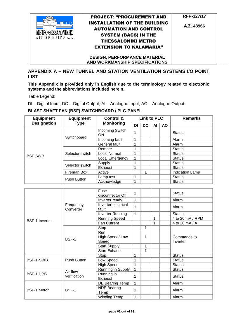
PROJECT: “PROCUREMENT AND
INSTALLATION OF THE BUILDING
AUTOMATION AND CONTROL
SYSTEM (BACS) IN THE
THESSALONIKI METRO
EXTENSION TO KALAMARIA”
DESIGN, PERFORMANCE MATERIAL
AND WORKMANSHIP SPECIFICATIONS
RFP-327/17
Α.Σ. 48966
page 62 out of 83
APPENDIX A – NEW TUNNEL AND STATION VENTILATION SYSTEMS I/O POINT LIST
This Appendix is provided only in English due to the terminology related to electronic systems and the abbreviations included herein.
Table Legend:
DI – Digital Input, DO – Digital Output, AI – Analogue Input, AO – Analogue Output.
BLAST SHAFT FAN (BSF) SWITCHBOARD / PLC-PANEL
Equipment Designation
Equipment Type
Control & Monitoring
Link to PLC Remarks
DI DO AI AO
BSF SWB
Switchboard
Incoming Switch ON
1 Status
Incoming fault 1 Alarm
General fault 1 Alarm
Selector switch
Remote 1 Status
Local Normal 1 Status
Local Emergency 1 Status
Selector switch Supply 1 Status
Exhaust 1 Status
Fireman Box Active 1 Indication Lamp
Push Button Lamp test 1 Status
Acknowledge 1 Status
BSF-1 Inverter
Frequency Converter
Fuse disconnector Off
1 Status
Inverter ready 1 Alarm
Inverter electrical fault
1 Alarm
Inverter Running 1 Status
Running Speed 1 4 to 20 mA / RPM
Fan Current 1 4 to 20 mA / A
BSF-1
Stop 1
Commands to Inverter
Run High Speed/ Low Speed
1
Start Supply 1
Start Exhaust 1
BSF-1-SWB Push Button
Stop 1 Status
Low Speed 1 Status
High Speed 1 Status
BSF-1 DPS Air flow verification
Running in Supply 1 Status
Running in Exhaust
1 Status
BSF-1 Motor BSF-1
DE Bearing Temp 1 Alarm
NDE Bearing Temp
1 Alarm
Winding Temp 1 Alarm
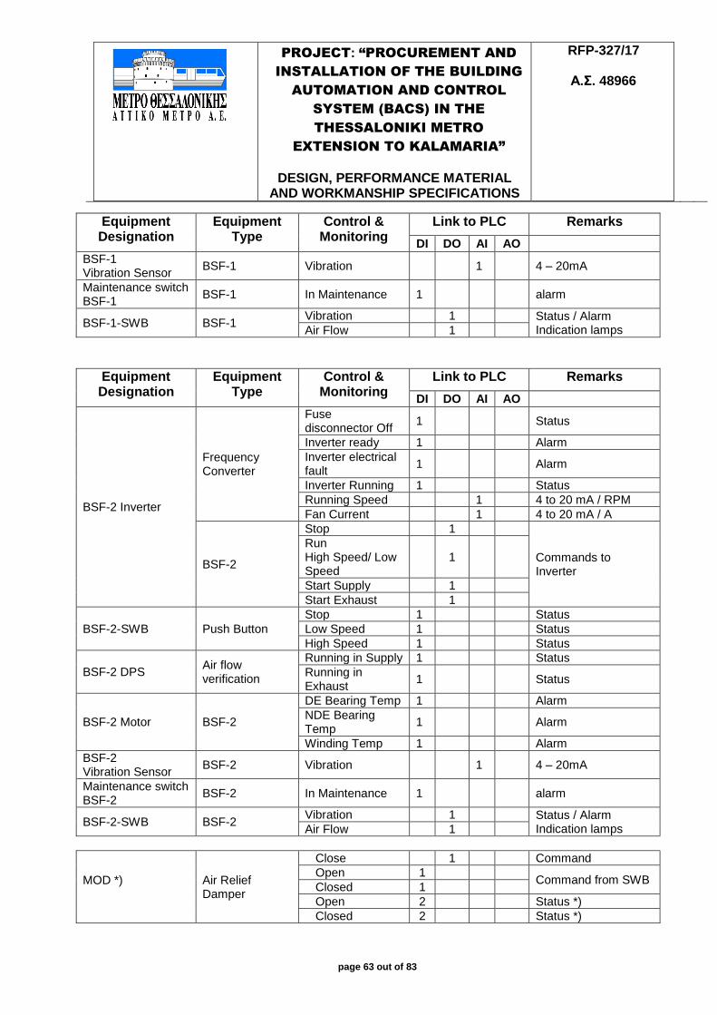
PROJECT: “PROCUREMENT AND
INSTALLATION OF THE BUILDING
AUTOMATION AND CONTROL
SYSTEM (BACS) IN THE
THESSALONIKI METRO
EXTENSION TO KALAMARIA”
DESIGN, PERFORMANCE MATERIAL
AND WORKMANSHIP SPECIFICATIONS
RFP-327/17
Α.Σ. 48966
page 63 out of 83
Equipment Designation
Equipment Type
Control & Monitoring
Link to PLC Remarks
DI DO AI AO BSF-1 Vibration Sensor
BSF-1 Vibration 1 4 – 20mA
Maintenance switch BSF-1
BSF-1 In Maintenance 1 alarm
BSF-1-SWB BSF-1 Vibration 1 Status / Alarm
Indication lamps Air Flow 1
Equipment Designation
Equipment Type
Control & Monitoring
Link to PLC Remarks
DI DO AI AO
BSF-2 Inverter
Frequency Converter
Fuse disconnector Off
1 Status
Inverter ready 1 Alarm
Inverter electrical fault
1 Alarm
Inverter Running 1 Status
Running Speed 1 4 to 20 mA / RPM
Fan Current 1 4 to 20 mA / A
BSF-2
Stop 1
Commands to Inverter
Run High Speed/ Low Speed
1
Start Supply 1
Start Exhaust 1
BSF-2-SWB Push Button
Stop 1 Status
Low Speed 1 Status
High Speed 1 Status
BSF-2 DPS Air flow verification
Running in Supply 1 Status
Running in Exhaust
1 Status
BSF-2 Motor BSF-2
DE Bearing Temp 1 Alarm
NDE Bearing Temp
1 Alarm
Winding Temp 1 Alarm
BSF-2 Vibration Sensor
BSF-2 Vibration 1 4 – 20mA
Maintenance switch BSF-2
BSF-2 In Maintenance 1 alarm
BSF-2-SWB BSF-2 Vibration 1 Status / Alarm
Indication lamps Air Flow 1
MOD *)
Air Relief Damper
Close 1 Command
Open 1 Command from SWB
Closed 1
Open 2 Status *)
Closed 2 Status *)
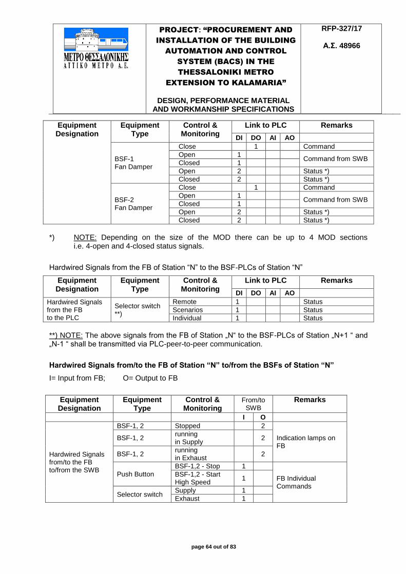
PROJECT: “PROCUREMENT AND
INSTALLATION OF THE BUILDING
AUTOMATION AND CONTROL
SYSTEM (BACS) IN THE
THESSALONIKI METRO
EXTENSION TO KALAMARIA”
DESIGN, PERFORMANCE MATERIAL
AND WORKMANSHIP SPECIFICATIONS
RFP-327/17
Α.Σ. 48966
page 64 out of 83
Equipment Designation
Equipment Type
Control & Monitoring
Link to PLC Remarks
DI DO AI AO
BSF-1 Fan Damper
Close 1 Command
Open 1 Command from SWB
Closed 1
Open 2 Status *)
Closed 2 Status *)
BSF-2 Fan Damper
Close 1 Command
Open 1 Command from SWB
Closed 1
Open 2 Status *)
Closed 2 Status *)
*) NOTE: Depending on the size of the MOD there can be up to 4 MOD sections i.e. 4-open and 4-closed status signals.
Hardwired Signals from the FB of Station “N” to the BSF-PLCs of Station “N”
Equipment Designation
Equipment Type
Control & Monitoring
Link to PLC Remarks
DI DO AI AO Hardwired Signals from the FB to the PLC
Selector switch **)
Remote 1 Status
Scenarios 1 Status
Individual 1 Status
**) NOTE: The above signals from the FB of Station „N“ to the BSF-PLCs of Station „N+1 “ and „N-1 “ shall be transmitted via PLC-peer-to-peer communication.
Hardwired Signals from/to the FB of Station “N” to/from the BSFs of Station “N”
I= Input from FB; O= Output to FB
Equipment Designation
Equipment Type
Control & Monitoring
From/to SWB
Remarks
I O
Hardwired Signals from/to the FB to/from the SWB
BSF-1, 2 Stopped 2
Indication lamps on FB
BSF-1, 2 running in Supply
2
BSF-1, 2 running in Exhaust
2
Push Button
BSF-1,2 - Stop 1
FB Individual Commands
BSF-1,2 - Start High Speed
1
Selector switch Supply 1
Exhaust 1

PROJECT: “PROCUREMENT AND
INSTALLATION OF THE BUILDING
AUTOMATION AND CONTROL
SYSTEM (BACS) IN THE
THESSALONIKI METRO
EXTENSION TO KALAMARIA”
DESIGN, PERFORMANCE MATERIAL
AND WORKMANSHIP SPECIFICATIONS
RFP-327/17
Α.Σ. 48966
page 65 out of 83
The exact number of control and monitoring data points necessary shall be determined during the detailed design phase of the Tunnel and Station Ventilation and HVAC Systems.
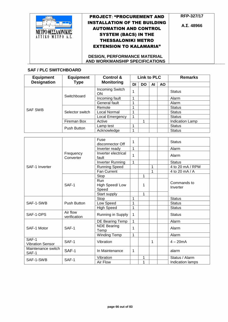
PROJECT: “PROCUREMENT AND
INSTALLATION OF THE BUILDING
AUTOMATION AND CONTROL
SYSTEM (BACS) IN THE
THESSALONIKI METRO
EXTENSION TO KALAMARIA”
DESIGN, PERFORMANCE MATERIAL
AND WORKMANSHIP SPECIFICATIONS
RFP-327/17
Α.Σ. 48966
page 66 out of 83
SAF / PLC SWITCHBOARD
Equipment Designation
Equipment Type
Control & Monitoring
Link to PLC Remarks
DI DO AI AO
SAF SWB
Switchboard
Incoming Switch ON
1 Status
Incoming fault 1 Alarm
General fault 1 Alarm
Selector switch
Remote 1 Status
Local Normal 1 Status
Local Emergency 1 Status
Fireman Box Active 1 Indication Lamp
Push Button Lamp test 1 Status
Acknowledge 1 Status
SAF-1 Inverter
Frequency Converter
Fuse disconnector Off
1 Status
Inverter ready 1 Alarm
Inverter electrical fault
1 Alarm
Inverter Running 1 Status
Running Speed 1 4 to 20 mA / RPM
Fan Current 1 4 to 20 mA / A
SAF-1
Stop 1
Commands to Inverter
Run High Speed/ Low Speed
1
Start supply 1
SAF-1-SWB Push Button
Stop 1 Status
Low Speed 1 Status
High Speed 1 Status
SAF-1-DPS Air flow verification
Running in Supply 1 Status
SAF-1 Motor SAF-1
DE Bearing Temp 1 Alarm
NDE Bearing Temp
1 Alarm
Winding Temp 1 Alarm
SAF-1 Vibration Sensor
SAF-1 Vibration 1 4 – 20mA
Maintenance switch SAF-1
SAF-1 In Maintenance 1 alarm
SAF-1-SWB SAF-1 Vibration 1 Status / Alarm
Indication lamps Air Flow 1
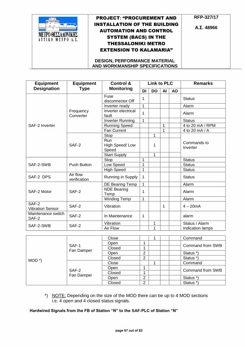
PROJECT: “PROCUREMENT AND
INSTALLATION OF THE BUILDING
AUTOMATION AND CONTROL
SYSTEM (BACS) IN THE
THESSALONIKI METRO
EXTENSION TO KALAMARIA”
DESIGN, PERFORMANCE MATERIAL
AND WORKMANSHIP SPECIFICATIONS
RFP-327/17
Α.Σ. 48966
page 67 out of 83
Equipment Designation
Equipment Type
Control & Monitoring
Link to PLC Remarks
DI DO AI AO
SAF-2 Inverter
Frequency Converter
Fuse disconnector Off
1 Status
Inverter ready 1 Alarm
Inverter electrical fault
1 Alarm
Inverter Running 1 Status
Running Speed 1 4 to 20 mA / RPM
Fan Current 1 4 to 20 mA / A
SAF-2
Stop 1
Commands to Inverter
Run High Speed/ Low Speed
1
Start Supply 1
SAF-2-SWB Push Button
Stop 1 Status
Low Speed 1 Status
High Speed 1 Status
SAF-2 DPS Air flow verification
Running in Supply 1 Status
SAF-2 Motor SAF-2
DE Bearing Temp 1 Alarm
NDE Bearing Temp
1 Alarm
Winding Temp 1 Alarm
SAF-2 Vibration Sensor
SAF-2 Vibration 1 4 – 20mA
Maintenance switch SAF-2
SAF-2 In Maintenance 1 alarm
SAF-2-SWB SAF-2 Vibration 1 Status / Alarm
Indication lamps Air Flow 1
MOD *)
SAF-1 Fan Damper
Close 1 Command
Open 1 Command from SWB
Closed 1
Open 2 Status *)
Closed 2 Status *)
SAF-2 Fan Damper
Close 1 Command
Open 1 Command from SWB
Closed 1
Open 2 Status *)
Closed 2 Status *)
*) NOTE: Depending on the size of the MOD there can be up to 4 MOD sections i.e. 4 open and 4 closed status signals.
Hardwired Signals from the FB of Station “N” to the SAF-PLC of Station “N”
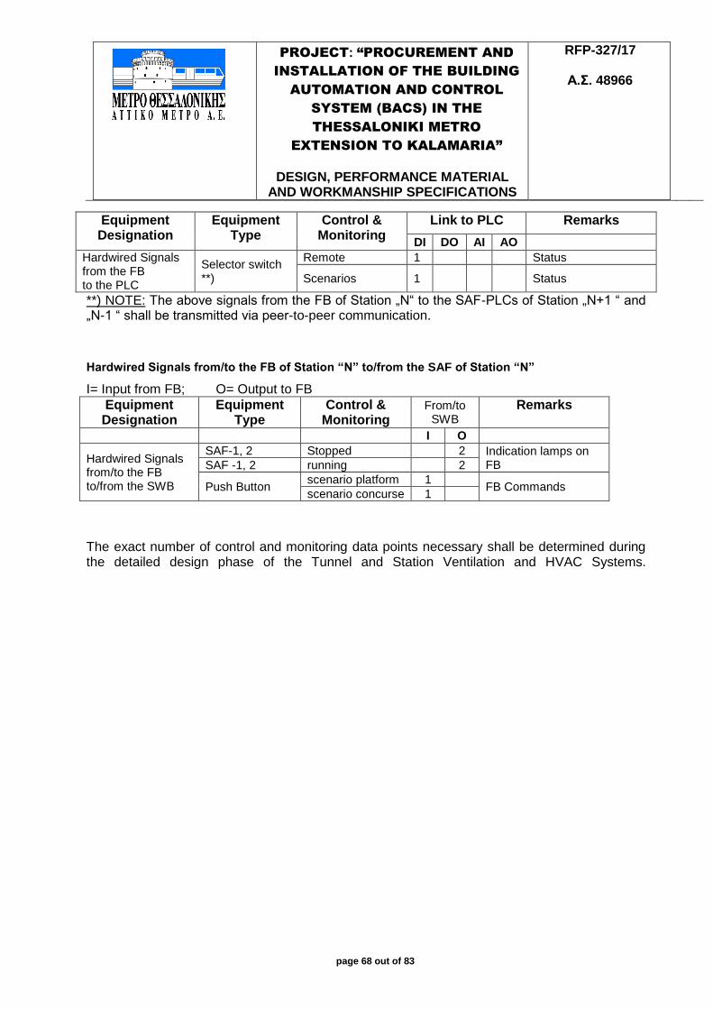
PROJECT: “PROCUREMENT AND
INSTALLATION OF THE BUILDING
AUTOMATION AND CONTROL
SYSTEM (BACS) IN THE
THESSALONIKI METRO
EXTENSION TO KALAMARIA”
DESIGN, PERFORMANCE MATERIAL
AND WORKMANSHIP SPECIFICATIONS
RFP-327/17
Α.Σ. 48966
page 68 out of 83
Equipment Designation
Equipment Type
Control & Monitoring
Link to PLC Remarks
DI DO AI AO Hardwired Signals from the FB to the PLC
Selector switch **)
Remote 1 Status
Scenarios 1 Status
**) NOTE: The above signals from the FB of Station „N“ to the SAF-PLCs of Station „N+1 “ and „N-1 “ shall be transmitted via peer-to-peer communication.
Hardwired Signals from/to the FB of Station “N” to/from the SAF of Station “N”
I= Input from FB; O= Output to FB
Equipment Designation
Equipment Type
Control & Monitoring
From/to SWB
Remarks
I O
Hardwired Signals from/to the FB to/from the SWB
SAF-1, 2 Stopped 2 Indication lamps on FB SAF -1, 2 running 2
Push Button scenario platform 1
FB Commands scenario concurse 1
The exact number of control and monitoring data points necessary shall be determined during the detailed design phase of the Tunnel and Station Ventilation and HVAC Systems.
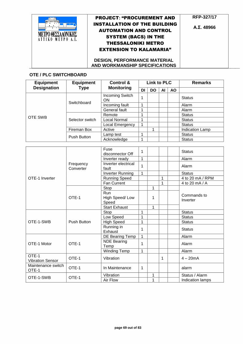
PROJECT: “PROCUREMENT AND
INSTALLATION OF THE BUILDING
AUTOMATION AND CONTROL
SYSTEM (BACS) IN THE
THESSALONIKI METRO
EXTENSION TO KALAMARIA”
DESIGN, PERFORMANCE MATERIAL
AND WORKMANSHIP SPECIFICATIONS
RFP-327/17
Α.Σ. 48966
page 69 out of 83
OTE / PLC SWITCHBOARD
Equipment Designation
Equipment Type
Control & Monitoring
Link to PLC Remarks
DI DO AI AO
OTE SWB
Switchboard
Incoming Switch ON
1 Status
Incoming fault 1 Alarm
General fault 1 Alarm
Selector switch
Remote 1 Status
Local Normal 1 Status
Local Emergency 1 Status
Fireman Box Active 1 Indication Lamp
Push Button Lamp test 1 Status
Acknowledge 1 Status
OTE-1 Inverter
Frequency Converter
Fuse disconnector Off
1 Status
Inverter ready 1 Alarm
Inverter electrical fault
1 Alarm
Inverter Running 1 Status
Running Speed 1 4 to 20 mA / RPM
Fan Current 1 4 to 20 mA / A
OTE-1
Stop 1
Commands to Inverter
Run High Speed/ Low Speed
1
Start Exhaust 1
OTE-1-SWB Push Button
Stop 1 Status
Low Speed 1 Status
High Speed 1 Status
Running in Exhaust
1 Status
OTE-1 Motor OTE-1
DE Bearing Temp 1 Alarm
NDE Bearing Temp
1 Alarm
Winding Temp 1 Alarm
OTE-1 Vibration Sensor
OTE-1 Vibration 1 4 – 20mA
Maintenance switch OTE-1
OTE-1 In Maintenance 1 alarm
OTE-1-SWB OTE-1 Vibration 1 Status / Alarm
Indication lamps Air Flow 1
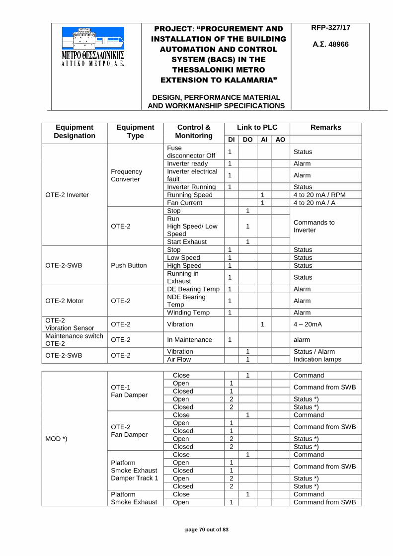
PROJECT: “PROCUREMENT AND
INSTALLATION OF THE BUILDING
AUTOMATION AND CONTROL
SYSTEM (BACS) IN THE
THESSALONIKI METRO
EXTENSION TO KALAMARIA”
DESIGN, PERFORMANCE MATERIAL
AND WORKMANSHIP SPECIFICATIONS
RFP-327/17
Α.Σ. 48966
page 70 out of 83
Equipment Designation
Equipment Type
Control & Monitoring
Link to PLC Remarks
DI DO AI AO
OTE-2 Inverter
Frequency Converter
Fuse disconnector Off
1 Status
Inverter ready 1 Alarm
Inverter electrical fault
1 Alarm
Inverter Running 1 Status
Running Speed 1 4 to 20 mA / RPM
Fan Current 1 4 to 20 mA / A
OTE-2
Stop 1
Commands to Inverter
Run High Speed/ Low Speed
1
Start Exhaust 1
OTE-2-SWB Push Button
Stop 1 Status
Low Speed 1 Status
High Speed 1 Status
Running in Exhaust
1 Status
OTE-2 Motor OTE-2
DE Bearing Temp 1 Alarm
NDE Bearing Temp
1 Alarm
Winding Temp 1 Alarm
OTE-2 Vibration Sensor
OTE-2 Vibration 1 4 – 20mA
Maintenance switch OTE-2
OTE-2 In Maintenance 1 alarm
OTE-2-SWB OTE-2 Vibration 1 Status / Alarm
Indication lamps Air Flow 1
MOD *)
OTE-1 Fan Damper
Close 1 Command
Open 1 Command from SWB
Closed 1
Open 2 Status *)
Closed 2 Status *)
OTE-2 Fan Damper
Close 1 Command
Open 1 Command from SWB
Closed 1
Open 2 Status *)
Closed 2 Status *)
Platform Smoke Exhaust Damper Track 1
Close 1 Command
Open 1 Command from SWB
Closed 1
Open 2 Status *)
Closed 2 Status *)
Platform Smoke Exhaust
Close 1 Command
Open 1 Command from SWB
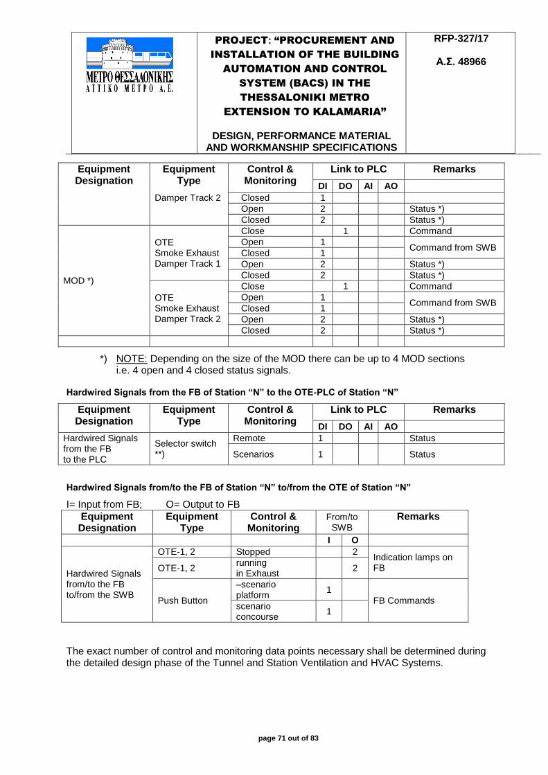
PROJECT: “PROCUREMENT AND
INSTALLATION OF THE BUILDING
AUTOMATION AND CONTROL
SYSTEM (BACS) IN THE
THESSALONIKI METRO
EXTENSION TO KALAMARIA”
DESIGN, PERFORMANCE MATERIAL
AND WORKMANSHIP SPECIFICATIONS
RFP-327/17
Α.Σ. 48966
page 71 out of 83
Equipment Designation
Equipment Type
Control & Monitoring
Link to PLC Remarks
DI DO AI AO Damper Track 2 Closed 1
Open 2 Status *)
Closed 2 Status *)
MOD *)
OTE Smoke Exhaust Damper Track 1
Close 1 Command
Open 1 Command from SWB
Closed 1
Open 2 Status *)
Closed 2 Status *)
OTE Smoke Exhaust Damper Track 2
Close 1 Command
Open 1 Command from SWB
Closed 1
Open 2 Status *)
Closed 2 Status *)
*) NOTE: Depending on the size of the MOD there can be up to 4 MOD sections i.e. 4 open and 4 closed status signals.
Hardwired Signals from the FB of Station “N” to the OTE-PLC of Station “N”
Equipment Designation
Equipment Type
Control & Monitoring
Link to PLC Remarks
DI DO AI AO Hardwired Signals from the FB to the PLC
Selector switch **)
Remote 1 Status
Scenarios 1 Status
Hardwired Signals from/to the FB of Station “N” to/from the OTE of Station “N”
I= Input from FB; O= Output to FB
Equipment Designation
Equipment Type
Control & Monitoring
From/to SWB
Remarks
I O
Hardwired Signals from/to the FB to/from the SWB
OTE-1, 2 Stopped 2 Indication lamps on FB OTE-1, 2
running in Exhaust
2
Push Button
–scenario platform
1
FB Commands scenario concourse
1
The exact number of control and monitoring data points necessary shall be determined during the detailed design phase of the Tunnel and Station Ventilation and HVAC Systems.

PROJECT: “PROCUREMENT AND
INSTALLATION OF THE BUILDING
AUTOMATION AND CONTROL
SYSTEM (BACS) IN THE
THESSALONIKI METRO
EXTENSION TO KALAMARIA”
DESIGN, PERFORMANCE MATERIAL
AND WORKMANSHIP SPECIFICATIONS
RFP-327/17
Α.Σ. 48966
page 72 out of 83
JET-FAN / PLC SWITCHBOARD
Equipment Designation
Equipment Type
Control & Monitoring
Link to PLC Remarks
DI DO AI AO
JF SWB
Switchboard
Incoming Switch ON
1 Status
Incoming fault 1 Alarm
General fault 1 Alarm
Selector switch
Remote 1 Status
Local Normal 1 Status
Local Emergency 1 Status
Selector switch Supply 1 Status
Exhaust 1 Status
Fireman Box Active 1 Indication Lamp
Push Button Lamp test 1 Status
Acknowledge 1 Status
JF
Jet Fan 1, 2
Running in Supply 2 Status
Running in Exhaust
2 Status
Fault 2 Alarm
DE Bearing Temp 2 Alarm
NDE Bearing Temp
2 Alarm
Winding Temp 2 Alarm
Vibration 2 4 to 20 mA
In Maintenance 2 Alarm
Start 2
Stop 2
JF-SWB Vibration 2 Status / Alarm
Indication lamps Air Flow 2
The exact number of control and monitoring data points necessary shall be determined during the detailed design phase of the Tunnel and Station Ventilation and HVAC Systems.
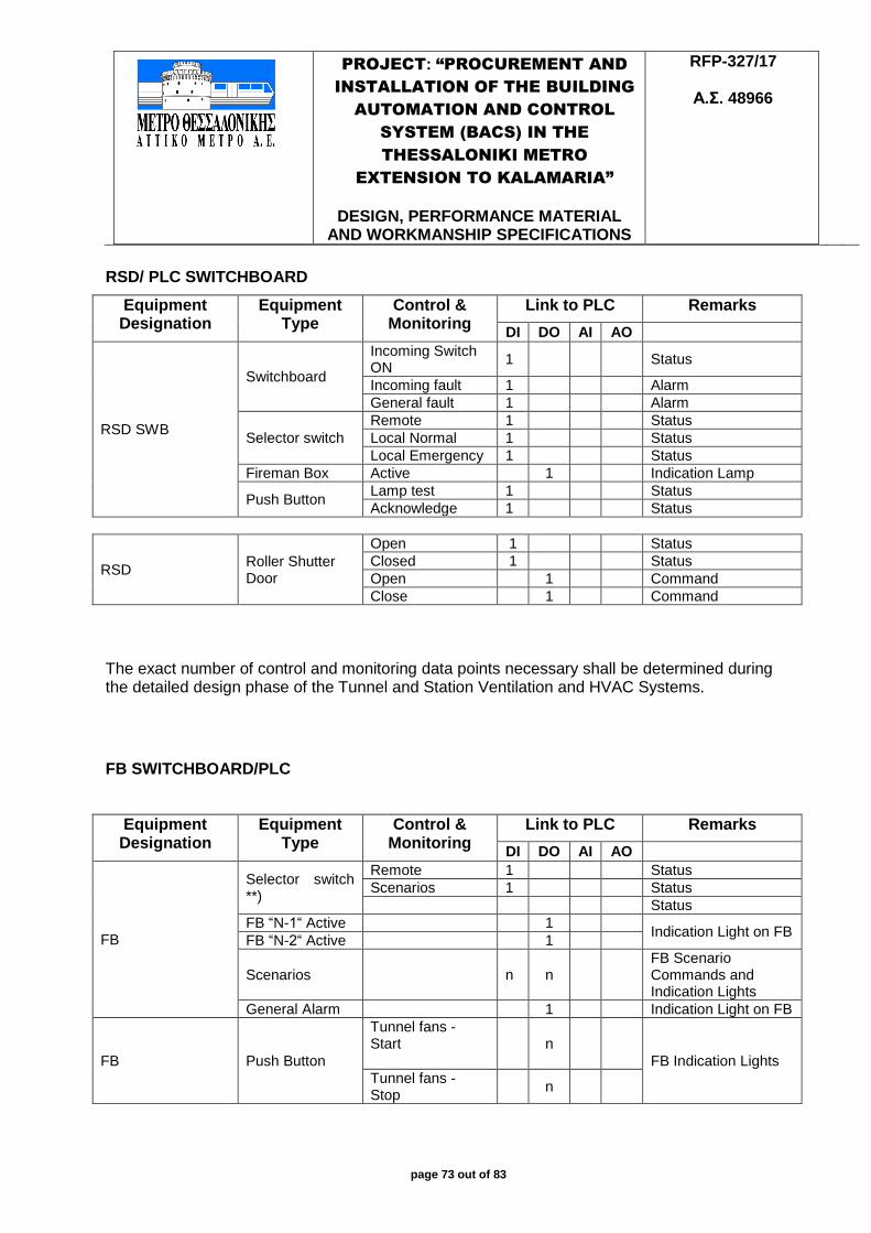
PROJECT: “PROCUREMENT AND
INSTALLATION OF THE BUILDING
AUTOMATION AND CONTROL
SYSTEM (BACS) IN THE
THESSALONIKI METRO
EXTENSION TO KALAMARIA”
DESIGN, PERFORMANCE MATERIAL
AND WORKMANSHIP SPECIFICATIONS
RFP-327/17
Α.Σ. 48966
page 73 out of 83
RSD/ PLC SWITCHBOARD
Equipment Designation
Equipment Type
Control & Monitoring
Link to PLC Remarks
DI DO AI AO
RSD SWB
Switchboard
Incoming Switch ON
1 Status
Incoming fault 1 Alarm
General fault 1 Alarm
Selector switch
Remote 1 Status
Local Normal 1 Status
Local Emergency 1 Status
Fireman Box Active 1 Indication Lamp
Push Button Lamp test 1 Status
Acknowledge 1 Status
RSD Roller Shutter Door
Open 1 Status
Closed 1 Status
Open 1 Command
Close 1 Command
The exact number of control and monitoring data points necessary shall be determined during the detailed design phase of the Tunnel and Station Ventilation and HVAC Systems.
FB SWITCHBOARD/PLC
Equipment Designation
Equipment Type
Control & Monitoring
Link to PLC Remarks
DI DO AI AO
FB
Selector switch **)
Remote 1 Status
Scenarios 1 Status
Status
FB “N-1“ Active 1 Indication Light on FB
FB “N-2“ Active 1
Scenarios n n FB Scenario Commands and Indication Lights
General Alarm 1 Indication Light on FB
FB Push Button
Tunnel fans - Start
n
FB Indication Lights
Tunnel fans - Stop
n
PROJECT: “PROCUREMENT AND
INSTALLATION OF THE BUILDING
AUTOMATION AND CONTROL
SYSTEM (BACS) IN THE
THESSALONIKI METRO
EXTENSION TO KALAMARIA”
DESIGN, PERFORMANCE MATERIAL
AND WORKMANSHIP SPECIFICATIONS
RFP-327/17
Α.Σ. 48966
page 74 out of 83
The exact number of control and monitoring data points necessary shall be determined during the detailed design phase of the Tunnel and Station Ventilation and HVAC Systems.
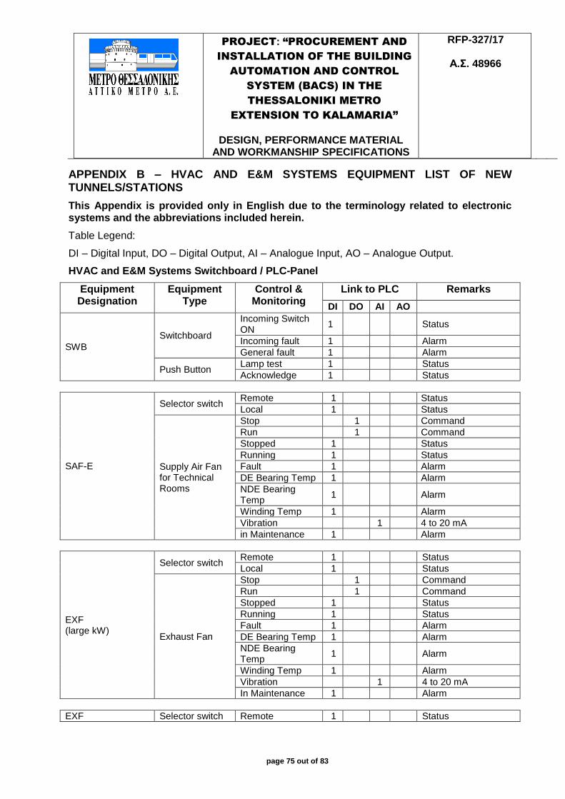
PROJECT: “PROCUREMENT AND
INSTALLATION OF THE BUILDING
AUTOMATION AND CONTROL
SYSTEM (BACS) IN THE
THESSALONIKI METRO
EXTENSION TO KALAMARIA”
DESIGN, PERFORMANCE MATERIAL
AND WORKMANSHIP SPECIFICATIONS
RFP-327/17
Α.Σ. 48966
page 75 out of 83
APPENDIX B – HVAC AND E&M SYSTEMS EQUIPMENT LIST OF NEW TUNNELS/STATIONS
This Appendix is provided only in English due to the terminology related to electronic systems and the abbreviations included herein.
Table Legend:
DI – Digital Input, DO – Digital Output, AI – Analogue Input, AO – Analogue Output.
HVAC and E&M Systems Switchboard / PLC-Panel
Equipment Designation
Equipment Type
Control & Monitoring
Link to PLC Remarks
DI DO AI AO
SWB
Switchboard
Incoming Switch ON
1 Status
Incoming fault 1 Alarm
General fault 1 Alarm
Push Button Lamp test 1 Status
Acknowledge 1 Status
SAF-E
Selector switch Remote 1 Status
Local 1 Status
Supply Air Fan for Technical Rooms
Stop 1 Command
Run 1 Command
Stopped 1 Status
Running 1 Status
Fault 1 Alarm
DE Bearing Temp 1 Alarm
NDE Bearing Temp
1 Alarm
Winding Temp 1 Alarm
Vibration 1 4 to 20 mA
in Maintenance 1 Alarm
EXF (large kW)
Selector switch Remote 1 Status
Local 1 Status
Exhaust Fan
Stop 1 Command
Run 1 Command
Stopped 1 Status
Running 1 Status
Fault 1 Alarm
DE Bearing Temp 1 Alarm
NDE Bearing Temp
1 Alarm
Winding Temp 1 Alarm
Vibration 1 4 to 20 mA
In Maintenance 1 Alarm
EXF Selector switch Remote 1 Status
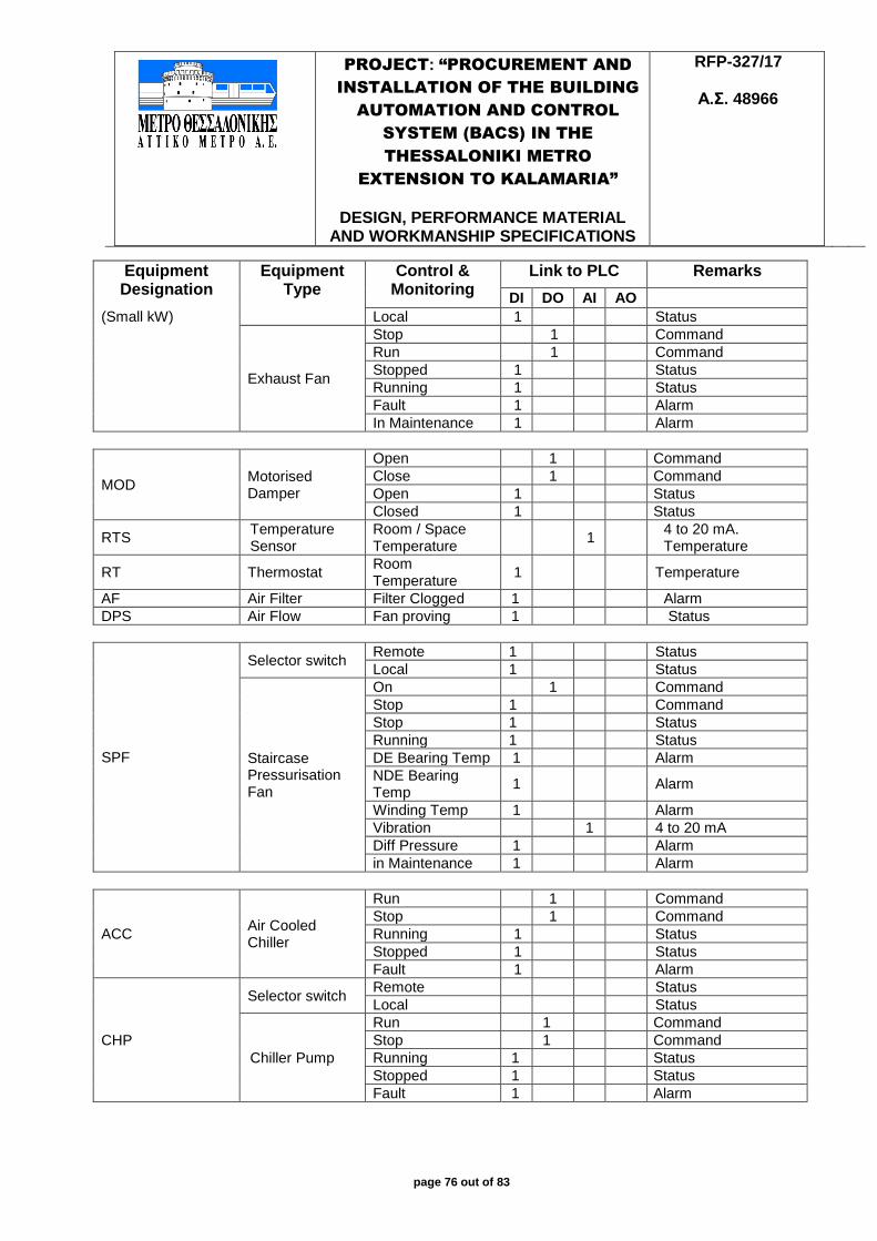
PROJECT: “PROCUREMENT AND
INSTALLATION OF THE BUILDING
AUTOMATION AND CONTROL
SYSTEM (BACS) IN THE
THESSALONIKI METRO
EXTENSION TO KALAMARIA”
DESIGN, PERFORMANCE MATERIAL
AND WORKMANSHIP SPECIFICATIONS
RFP-327/17
Α.Σ. 48966
page 76 out of 83
Equipment Designation
Equipment Type
Control & Monitoring
Link to PLC Remarks
DI DO AI AO (Small kW) Local 1 Status
Exhaust Fan
Stop 1 Command
Run 1 Command
Stopped 1 Status
Running 1 Status
Fault 1 Alarm
In Maintenance 1 Alarm
MOD Motorised Damper
Open 1 Command
Close 1 Command
Open 1 Status
Closed 1 Status
RTS Temperature Sensor
Room / Space Temperature
1 4 to 20 mA. Temperature
RT Thermostat Room Temperature
1 Temperature
AF Air Filter Filter Clogged 1 Alarm
DPS Air Flow Fan proving 1 Status
SPF
Selector switch Remote 1 Status
Local 1 Status
Staircase Pressurisation Fan
On 1 Command
Stop 1 Command
Stop 1 Status
Running 1 Status
DE Bearing Temp 1 Alarm
NDE Bearing Temp
1 Alarm
Winding Temp 1 Alarm
Vibration 1 4 to 20 mA
Diff Pressure 1 Alarm
in Maintenance 1 Alarm
ACC Air Cooled Chiller
Run 1 Command
Stop 1 Command
Running 1 Status
Stopped 1 Status
Fault 1 Alarm
CHP
Selector switch Remote Status
Local Status
Chiller Pump
Run 1 Command
Stop 1 Command
Running 1 Status
Stopped 1 Status
Fault 1 Alarm
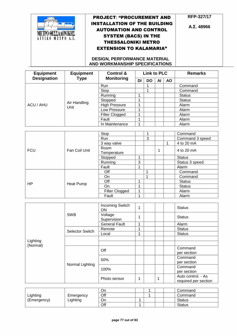
PROJECT: “PROCUREMENT AND
INSTALLATION OF THE BUILDING
AUTOMATION AND CONTROL
SYSTEM (BACS) IN THE
THESSALONIKI METRO
EXTENSION TO KALAMARIA”
DESIGN, PERFORMANCE MATERIAL
AND WORKMANSHIP SPECIFICATIONS
RFP-327/17
Α.Σ. 48966
page 77 out of 83
Equipment Designation
Equipment Type
Control & Monitoring
Link to PLC Remarks
DI DO AI AO
ACU / AHU Air Handling Unit
Run 1 Command
Stop 1 Command
Running 1 Status
Stopped 1 Status
High Pressure 1 Alarm
Low Pressure 1 Alarm
Filter Clogged 1 Alarm
Fault 1 Alarm
In Maintenance 1 Alarm
FCU Fan Coil Unit
Stop 1 Command
Run 3 Command 3 speed
3 way valve 1 4 to 20 mA
Room Temperature
1 4 to 20 mA
Stopped 1 Status
Running 3 Status 3 speed
Fault 1 Alarm
HP Heat Pump
Off 1 Command
On 1 Command
Off 1 Status
On 1 Status
Filter Clogged 1 Alarm
Fault 1 Alarm
Lighting (Normal)
SWB
Incoming Switch ON
1 Status
Voltage Supervision
1 Status
General Fault 1 Alarm
Selector Switch Remote 1 Status
Local 1 Status
Normal Lighting
Off 1 Command per section
50% 1 Command per section
100% 1 Command per section
Photo sensor 1 1 Auto control. - As required per section
Lighting (Emergency)
Emergency Lighting
On 1 Command
Off 1 Command
On 1 Status
Off 1 Status
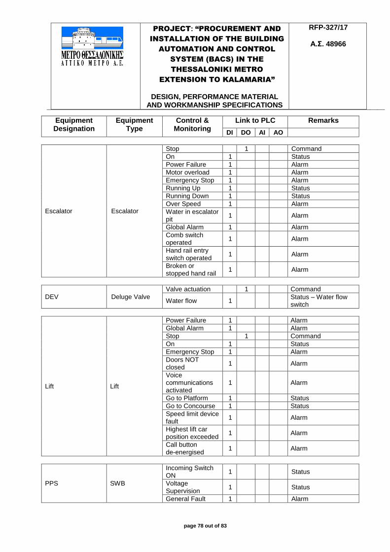
PROJECT: “PROCUREMENT AND
INSTALLATION OF THE BUILDING
AUTOMATION AND CONTROL
SYSTEM (BACS) IN THE
THESSALONIKI METRO
EXTENSION TO KALAMARIA”
DESIGN, PERFORMANCE MATERIAL
AND WORKMANSHIP SPECIFICATIONS
RFP-327/17
Α.Σ. 48966
page 78 out of 83
Equipment Designation
Equipment Type
Control & Monitoring
Link to PLC Remarks
DI DO AI AO
Escalator Escalator
Stop 1 Command
On 1 Status
Power Failure 1 Alarm
Motor overload 1 Alarm
Emergency Stop 1 Alarm
Running Up 1 Status
Running Down 1 Status
Over Speed 1 Alarm
Water in escalator pit
1 Alarm
Global Alarm 1 Alarm
Comb switch operated
1 Alarm
Hand rail entry switch operated
1 Alarm
Broken or stopped hand rail
1 Alarm
DEV Deluge Valve
Valve actuation 1 Command
Water flow 1 Status – Water flow switch
Lift Lift
Power Failure 1 Alarm
Global Alarm 1 Alarm
Stop 1 Command
On 1 Status
Emergency Stop 1 Alarm
Doors NOT closed
1 Alarm
Voice communications activated
1 Alarm
Go to Platform 1 Status
Go to Concourse 1 Status
Speed limit device fault
1 Alarm
Highest lift car position exceeded
1 Alarm
Call button de-energised
1 Alarm
PPS SWB
Incoming Switch ON
1 Status
Voltage Supervision
1 Status
General Fault 1 Alarm
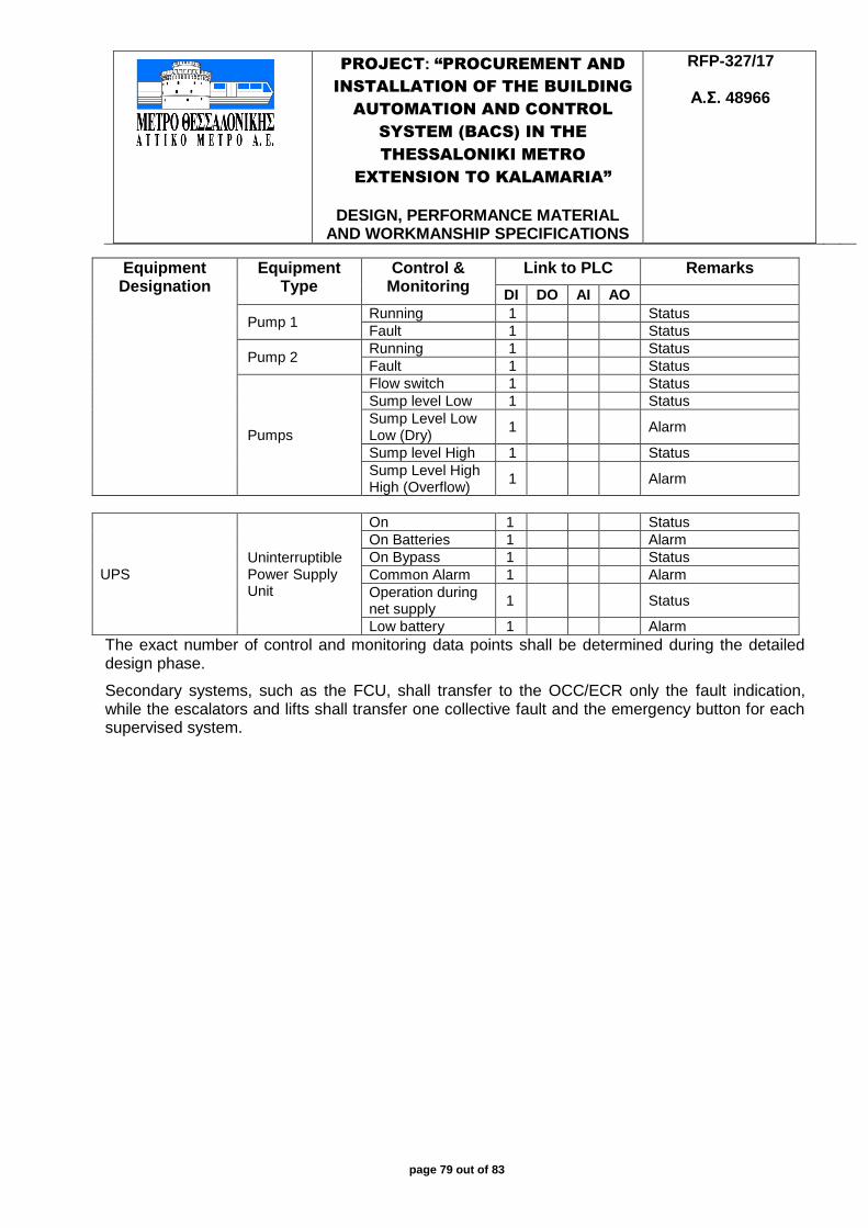
PROJECT: “PROCUREMENT AND
INSTALLATION OF THE BUILDING
AUTOMATION AND CONTROL
SYSTEM (BACS) IN THE
THESSALONIKI METRO
EXTENSION TO KALAMARIA”
DESIGN, PERFORMANCE MATERIAL
AND WORKMANSHIP SPECIFICATIONS
RFP-327/17
Α.Σ. 48966
page 79 out of 83
Equipment Designation
Equipment Type
Control & Monitoring
Link to PLC Remarks
DI DO AI AO
Pump 1 Running 1 Status
Fault 1 Status
Pump 2 Running 1 Status
Fault 1 Status
Pumps
Flow switch 1 Status
Sump level Low 1 Status
Sump Level Low Low (Dry)
1 Alarm
Sump level High 1 Status
Sump Level High High (Overflow)
1 Alarm
UPS Uninterruptible Power Supply Unit
On 1 Status
On Batteries 1 Alarm
On Bypass 1 Status
Common Alarm 1 Alarm
Operation during net supply
1 Status
Low battery 1 Alarm
The exact number of control and monitoring data points shall be determined during the detailed design phase.
Secondary systems, such as the FCU, shall transfer to the OCC/ECR only the fault indication, while the escalators and lifts shall transfer one collective fault and the emergency button for each supervised system.
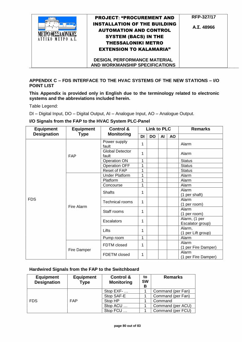
PROJECT: “PROCUREMENT AND
INSTALLATION OF THE BUILDING
AUTOMATION AND CONTROL
SYSTEM (BACS) IN THE
THESSALONIKI METRO
EXTENSION TO KALAMARIA”
DESIGN, PERFORMANCE MATERIAL
AND WORKMANSHIP SPECIFICATIONS
RFP-327/17
Α.Σ. 48966
page 80 out of 83
APPENDIX C – FDS INTERFACE TO THE HVAC SYSTEMS OF THE NEW STATIONS – I/O POINT LIST
This Appendix is provided only in English due to the terminology related to electronic systems and the abbreviations included herein.
Table Legend:
DI – Digital Input, DO – Digital Output, AI – Analogue Input, AO – Analogue Output.
I/O Signals from the FAP to the HVAC System PLC-Panel
Equipment Designation
Equipment Type
Control & Monitoring
Link to PLC Remarks
DI DO AI AO
FDS
FAP
Power supply fault
1 Alarm
Global Detector fault
1 Alarm
Operation ON 1 Status
Operation OFF 1 Status
Reset of FAP 1 Status
Fire Alarm
Under Platform 1 Alarm
Platform 1 Alarm
Concourse 1 Alarm
Shafts 1 Alarm (1 per shaft)
Technical rooms 1 Alarm (1 per room)
Staff rooms 1 Alarm (1 per room)
Escalators 1 Alarm, (1 per Escalator group)
Lifts 1 Alarm, (1 per Lift group)
Pump room 1 Alarm
Fire Damper
FDTM closed 1 Alarm (1 per Fire Damper)
FDETM closed 1 Alarm (1 per Fire Damper)
Hardwired Signals from the FAP to the Switchboard
Equipment Designation
Equipment Type
Control & Monitoring
to SWB
Remarks
FDS FAP
Stop EXF- … 1 Command (per Fan)
Stop SAF-E 1 Command (per Fan)
Stop HP 1 Command
Stop ACU … 1 Command (per ACU)
Stop FCU … 1 Command (per FCU)
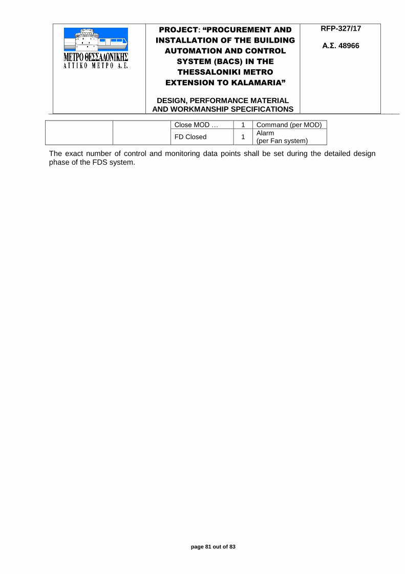
PROJECT: “PROCUREMENT AND
INSTALLATION OF THE BUILDING
AUTOMATION AND CONTROL
SYSTEM (BACS) IN THE
THESSALONIKI METRO
EXTENSION TO KALAMARIA”
DESIGN, PERFORMANCE MATERIAL
AND WORKMANSHIP SPECIFICATIONS
RFP-327/17
Α.Σ. 48966
page 81 out of 83
Close MOD … 1 Command (per MOD)
FD Closed 1 Alarm (per Fan system)
The exact number of control and monitoring data points shall be set during the detailed design phase of the FDS system.

PROJECT: “PROCUREMENT AND
INSTALLATION OF THE BUILDING
AUTOMATION AND CONTROL
SYSTEM (BACS) IN THE
THESSALONIKI METRO
EXTENSION TO KALAMARIA”
DESIGN, PERFORMANCE MATERIAL
AND WORKMANSHIP SPECIFICATIONS
RFP-327/17
Α.Σ. 48966
page 82 out of 83
APPENDIX D – AUTOMATIC FARE COLLECTION SYSTEM INTERFACE TO THE BACS SYSTEM – I/O POINT LIST
Equipment Designation
Equipment Type
Control & Monitoring
Link to PLC Remarks
DI DO AI AO
AFCS
SWB
Global Detector fault
1 Alarm
Selector Switch Local/Remote
1 Alarm
AFCS
Open command to the doors
1 Command
Power off of AFCS
1 Command
Open status per door n
Indication
FAP Command from FAP AFCS to open the doors
1 Indication

BUILDING AUTOMATION AND CONTROL SYSTEM OF THE ATHENS METRO
DESIGN, PERFORMANCE, MATERIAL AND WORKMANSHIP SPECIFICATIONS
RFP184/08
page 83 out of 83