Design of steel structures I - Dronacharya College of...
32
DESIGN OF DESIGN OF STEEL STRUCTURES STEEL STRUCTURES Design of slab and Gusset bases:‐
Transcript of Design of steel structures I - Dronacharya College of...
DESIGN OFDESIGN OFSTEEL STRUCTURESSTEEL STRUCTURES
Design of slab and Gusset bases:‐
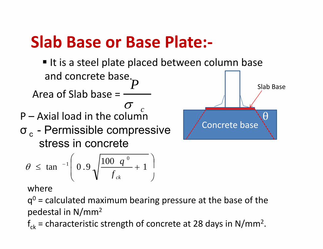
Slab Base or Base Plate:‐Slab Base or Base Plate:It is a steel plate placed between column baseand concrete baseand concrete base.
Area of Slab base = c
Pσ
Slab Base
cP – Axial load in the columnσ c - Permissible compressive
t i t
Concrete base
stress in concrete
⎟⎟⎞
⎜⎜⎛
+≤ − 11009.0tan0
1
fqθ ⎟
⎠⎜⎝ ckf
whereq0 = calculated maximum bearing pressure at the base of theq calculated maximum bearing pressure at the base of the pedestal in N/mm2
fck = characteristic strength of concrete at 28 days in N/mm2.
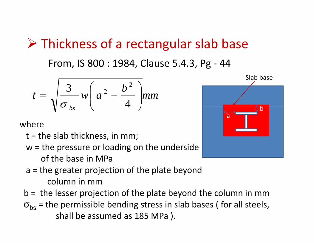
Thickness of a rectangular slab baseThickness of a rectangular slab baseFrom, IS 800 : 1984, Clause 5.4.3, Pg ‐ 44
Sl b b
mmbawtb
⎟⎟⎠
⎞⎜⎜⎝
⎛−=
43 2
2
σ
Slab base
bbs ⎠⎝ 4σbwhere
t = the slab thickness in mm;
ab
t = the slab thickness, in mm;w = the pressure or loading on the underside
of the base in MPath t j ti f th l t b da = the greater projection of the plate beyond column in mm
b = the lesser projection of the plate beyond the column in mmσbs = the permissible bending stress in slab bases ( for all steels,
shall be assumed as 185 MPa ).
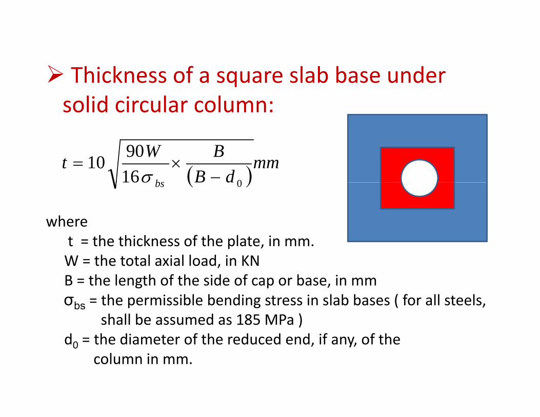
Thickness of a square slab base underThickness of a square slab base under solid circular column:
( )mmdB
BWtbs 016
9010−
×=σ ( )dBbs 016σ
wheret = the thickness of the plate, in mm.W = the total axial load, in KNB = the length of the side of cap or base, in mmg p ,σbs = the permissible bending stress in slab bases ( for all steels,
shall be assumed as 185 MPa )d = the diameter of the reduced end if any of thed0 = the diameter of the reduced end, if any, of the
column in mm.
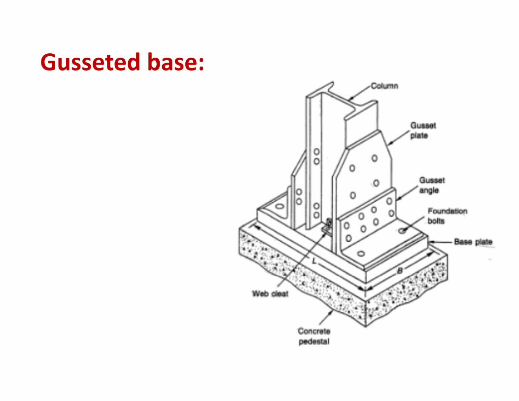
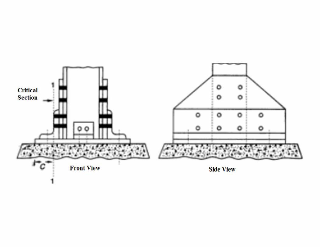
Gusseted base:
Grillage Foundation:‐Grillage Foundation:It is provided at shallow depth for column carrying heavy
Load on weak soil It consists of two or more layers of steelLoad on weak soil. It consists of two or more layers of steelBeams completely encased in concrete.The permissible stress in grillage beam may be increased byp g g y y
33.5% (50% in case of WL or EQ ). If the following conditionare satisfied
h b l l1. The beam are unpainted and solidly encased in ordinarydense concrete with 10mm aggregate and minimum f = 15 Mpafck = 15 Mpa.
2. Minimum distance between edge of flange is 75 mm.
3. Minimum concrete cover is 100 mm.

Design a grillage foundation for axial load 2500 KNand in column section two ISMC 250 with two coverand in column section two ISMC 250, with two cover Plates 300x25 mm.
Minimum required widthof slab base
1152252250 ×+×+=w 1152252250 ×+×+w
mmw 530=
mmw 600=Assume,
232 hwl +=
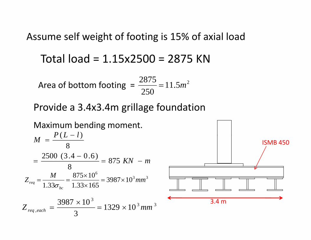
Assume self weight of footing is 15% of axial load
Total load = 1.15x2500 = 2875 KN
Area of bottom footing = 25.112502875 m=
P id 3 4 3 4 ill f d tiProvide a 3.4x3.4m grillage foundation
Maximum bending moment.lLP − )(
mKN
lLPM
−=−
=
−=
8758
)6.04.3(25008
)(ISMB 450
833
6
10398716533.110875
33.1mmMZ
bcreq ×=
××
==σ
3.4 m333
, 1013293
103987 mmZ eachreq ×=×
=
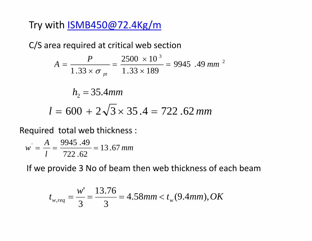
C/S area required at critical web section
Try with [email protected]/m
C/S area required at critical web section
23
49.994518933.1102500
33.1mmPA
pt
=××
=×
=σ pt
mmh 4.352 =
mml 62.7224.3532600 =×+=
Required total web thickness :
mmlAw 67.13
62.72249.9945' ===
If id 3 N f b th b thi k f h b
OKmmtmmwt )49(58476.13'<===
If we provide 3 No of beam then web thickness of each beam
OKmmtmmt wreqw ),4.9(58.433, <===
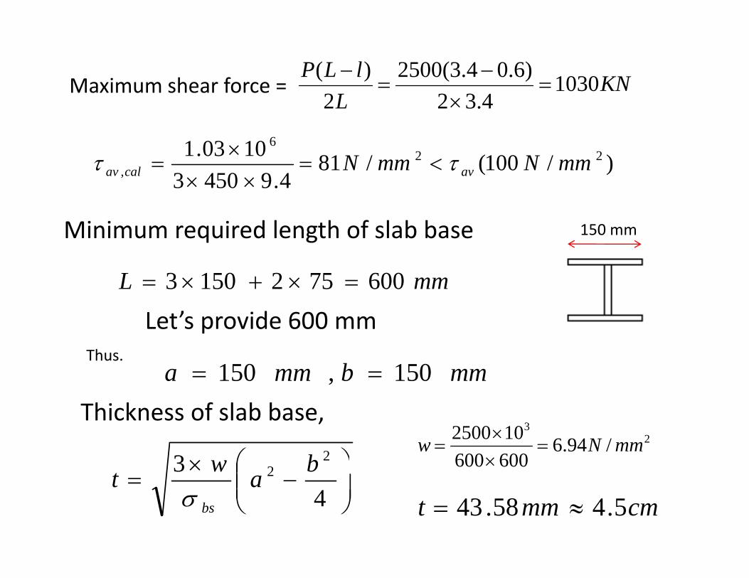
Maximum shear force = KNL
lLP 10304.32
)6.04.3(25002
)(=
×−
=−L 4.322 ×
)/100(/81494503
1003.1 226
, mmNmmN avcalav ττ <=××
×=
Minimum required length of slab base
4.94503 ××
150 mm
mmL 6007521503 =×+×=
Let’s provide 600 mmLet s provide 600 mmThus.
mmbmma 150,150 ==
Thickness of slab base,
⎟⎞
⎜⎛×3 2
2 bw2
3
/94.6600600102500 mmNw =
××
=
⎟⎟⎠
⎞⎜⎜⎝
⎛−=
43 2 bawt
bsσ cmmmt 5.458.43 ≈=
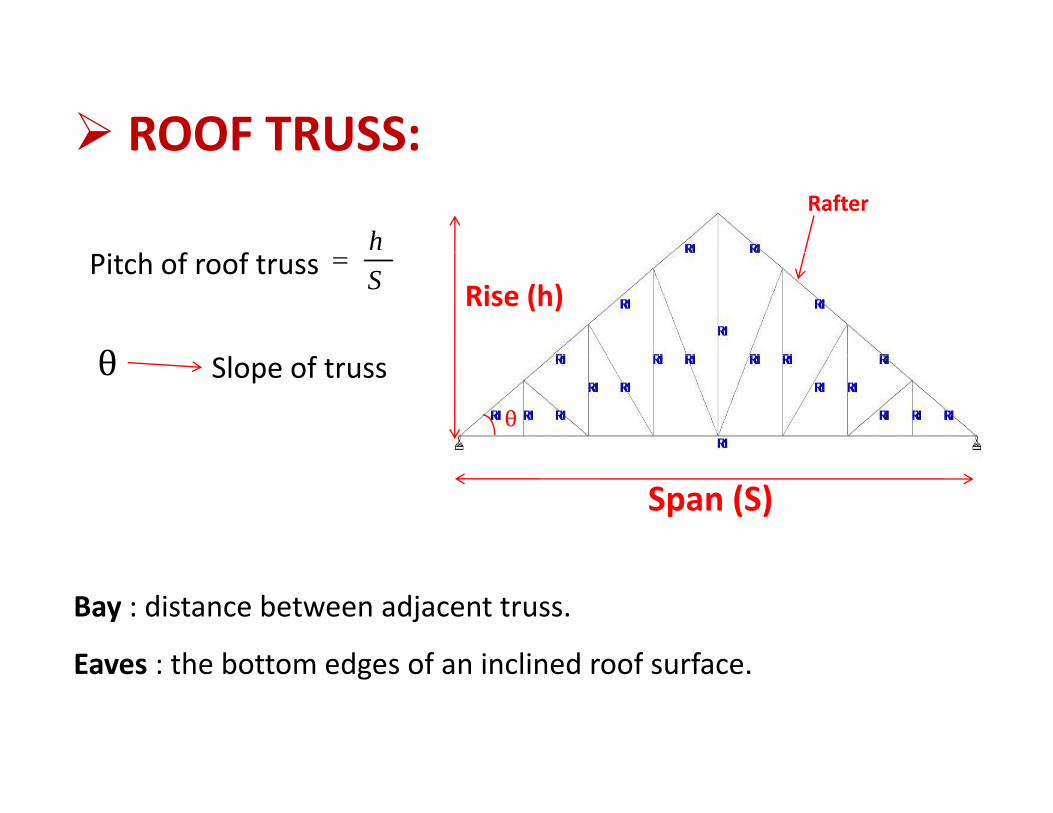
ROOF TRUSS: ROOF TRUSS:Rafter
h f fh
Rise (h)Pitch of roof truss S
=
θ
Slope of truss
Span (S)
Bay : distance between adjacent truss.
Eaves : the bottom edges of an inclined roof surfaceEaves : the bottom edges of an inclined roof surface.
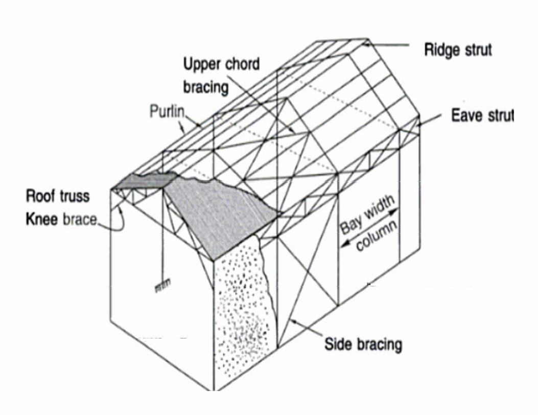
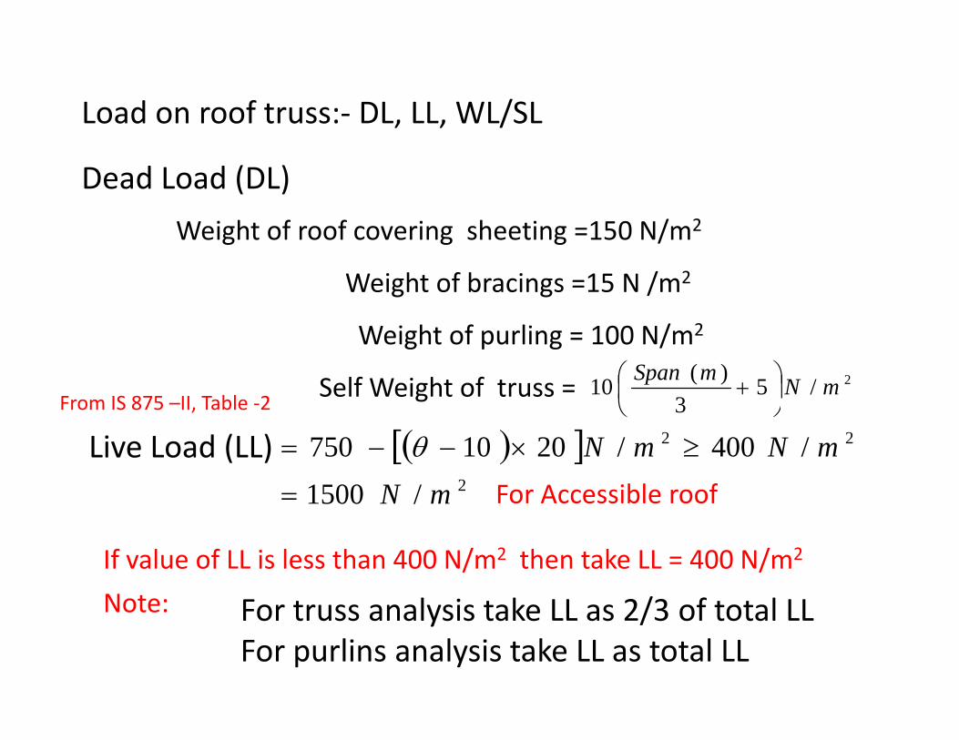
Load on roof truss:‐ DL, LL, WL/SL
Dead Load (DL)
Weight of roof covering sheeting =150 N/m2Weight of roof covering sheeting =150 N/m2
Weight of bracings =15 N /m2
/ 2Weight of purling = 100 N/m2
Self Weight of truss = 2/53
)(10 mNmSpan⎟⎠⎞
⎜⎝⎛ +
From IS 875 –II, Table ‐2 ⎠⎝
Live Load (LL) ( )[ ]2
22
/1500/400/2010750
mNmNmN
=
≥×−−= θFor Accessible roof
If value of LL is less than 400 N/m2 then take LL = 400 N/m2
F t l i t k LL 2/3 f t t l LLNote: For truss analysis take LL as 2/3 of total LLFor purlins analysis take LL as total LL
Note:
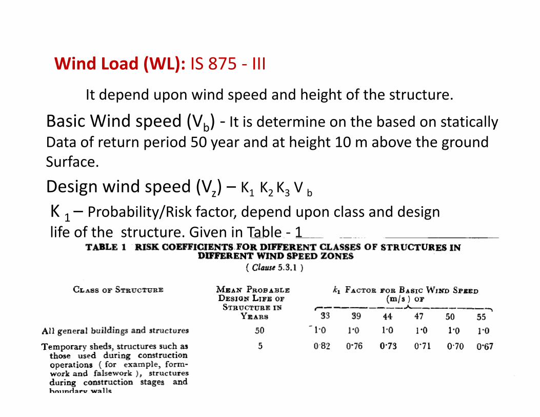
Wind Load (WL): IS 875 ‐ III
It depend upon wind speed and height of the structure.
Basic Wind speed (Vb) ‐ It is determine on the based on statically p ( b)Data of return period 50 year and at height 10 m above the groundSurface.
D i i d d (V ) K K K VDesign wind speed (Vz) – K1 K2 K3 V bK 1 – Probability/Risk factor, depend upon class and design life of the structure Given in Table ‐ 1life of the structure. Given in Table 1

K 2 – Depend upon height, terrain category and class of the structure. Given in Table – 2 3Given in Table – 2,3.

Class of structureIf any maximum dimension of the structure (Length, width, height)y ( g g )
< 20 m – A, 20 – 50 m – B, > 50 m ‐ C
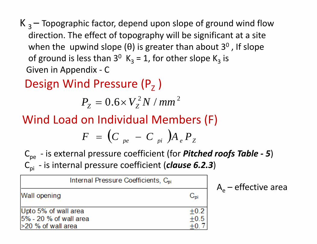
K 3 – Topographic factor, depend upon slope of ground wind flow direction. The effect of topography will be significant at a site h th i d l (θ) i t th b t 30 If lwhen the upwind slope (θ) is greater than about 30 , If slope
of ground is less than 30 K3 = 1, for other slope K3 is Given in Appendix ‐ C
Design Wind Pressure (PZ )22 /6.0 mmNVP ZZ ×= ZZ
Wind Load on Individual Members (F)( ) PACCF −= ( ) Zepipe PACCF =
Cpe ‐ is external pressure coefficient (for Pitched roofs Table ‐ 5)Cpi ‐ is internal pressure coefficient (clause 6.2.3)pi p ( )
Ae – effective area
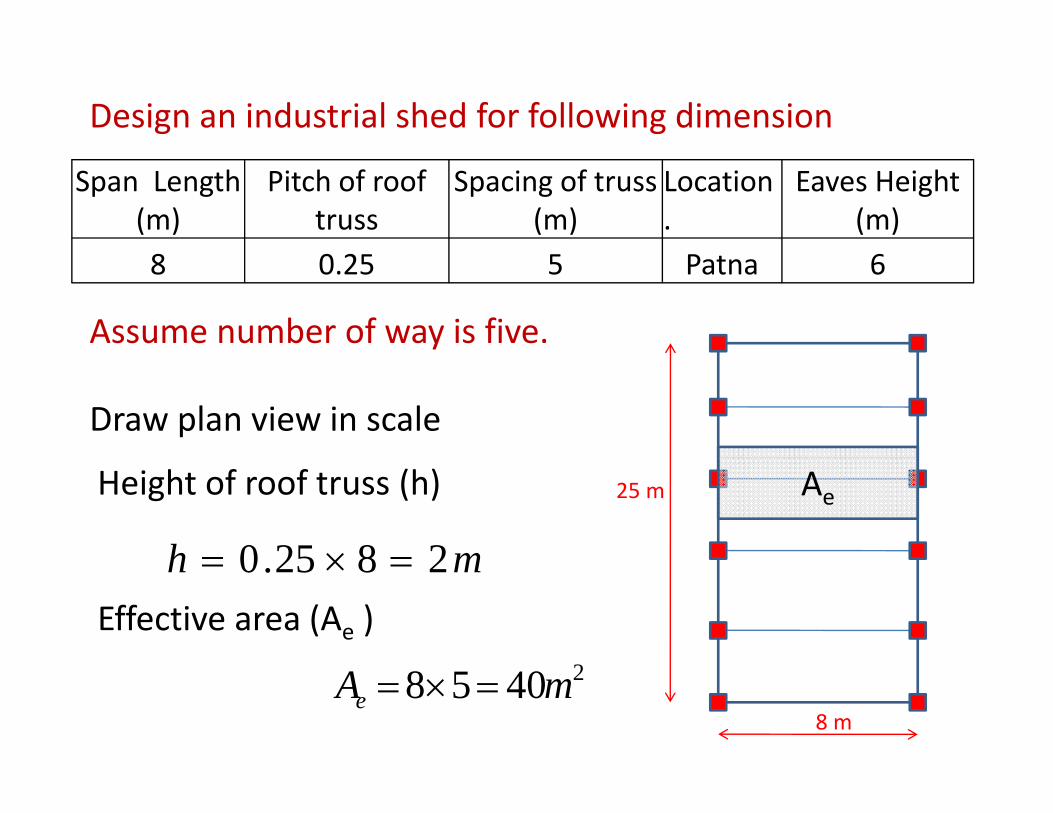
Design an industrial shed for following dimension
Span Length (m)
Pitch of roof truss
Spacing of truss (m)
Location.
Eaves Height (m)
8 0.25 5 Patna 6
Assume number of way is five.
Draw plan view in scale
25 mHeight of roof truss (h)
mh 28250 =×=
Ae
mh 2825.0 =×=Effective area (Ae )
8 m
24058 mAe =×=
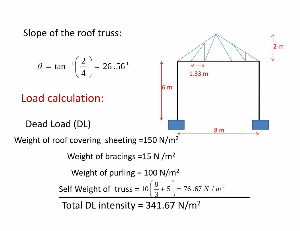
Slope of the roof truss:
1 33
2 m
01 56.2642tan =⎟⎠⎞
⎜⎝⎛= −θ
1.33 m
6 m
Load calculation:
4 ⎠⎝
8 mDead Load (DL)
Load calculation:
8 m
Weight of roof covering sheeting =150 N/m2
Weight of bracings =15 N /m2g g /
Weight of purling = 100 N/m2
Self Weight of truss = 2/67765810 mN⎟⎞
⎜⎛ +Self Weight of truss = /67.765
310 mN=⎟
⎠⎜⎝
+
Total DL intensity = 341.67 N/m2
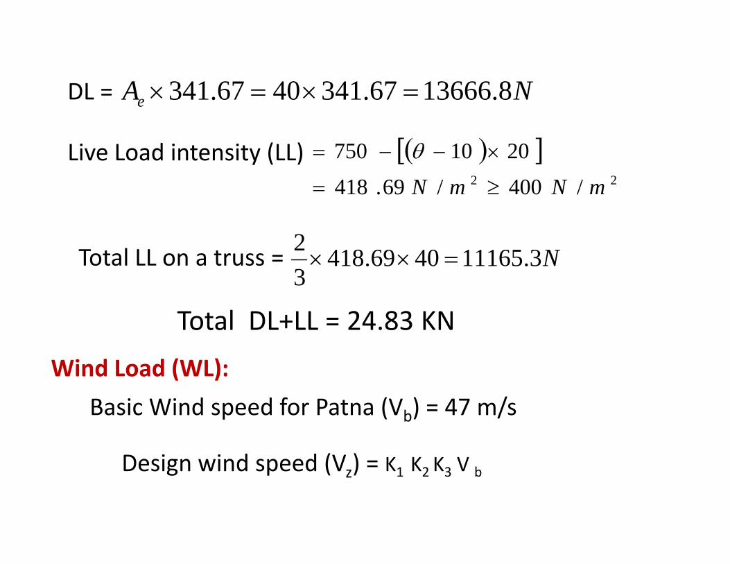
DL = NAe 8.1366667.3414067.341 =×=×e
Live Load intensity (LL) ( )[ ]2010750 ×−−= θ22 /400/69.418 mNmN ≥=
2Total LL on a truss = N3.111654069.418
32
=××
Total DL+LL 24 83 KNTotal DL+LL = 24.83 KN
Wind Load (WL):
Basic Wind speed for Patna (Vb) = 47 m/s
Design wind speed (V ) K K K VDesign wind speed (Vz) = K1 K2 K3 V b
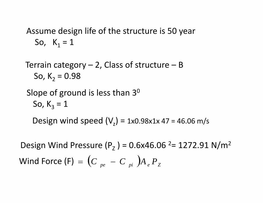
Assume design life of the structure is 50 yearSo, K1 = 1
T i t 2 Cl f t t BTerrain category – 2, Class of structure – BSo, K2 = 0.98
Slope of ground is less than 30
So, K3 = 1
Design wind speed (Vz) = 1x0.98x1x 47 = 46.06 m/s
Design Wind Pressure (PZ ) = 0.6x46.06 2= 1272.91 N/m2
Wind Force (F) ( ) Zepipe PACC −= ( ) Zepipe

External pressure coefficient on roof, IS 875 (III), Table ‐ 5
2375.0
86
21
<==<wh
Roof angle ( ) =26.560
0.5Wind
0.372Case – I, 0
Assume wall opening is less then 5%
Wind – ward direction:566 ⎞⎛ 0.2
p gInternal pressure coefficient (Cpi ) = 0.2
372.01056.65.07.0 −=⎟
⎠⎞
⎜⎝⎛ ×−−=
0
( ) 572.0−=− pipe CC
Lee – ward direction= ‐ 0.5
( )maxpipe
( )( ) 7.0max
−=− pipe CC
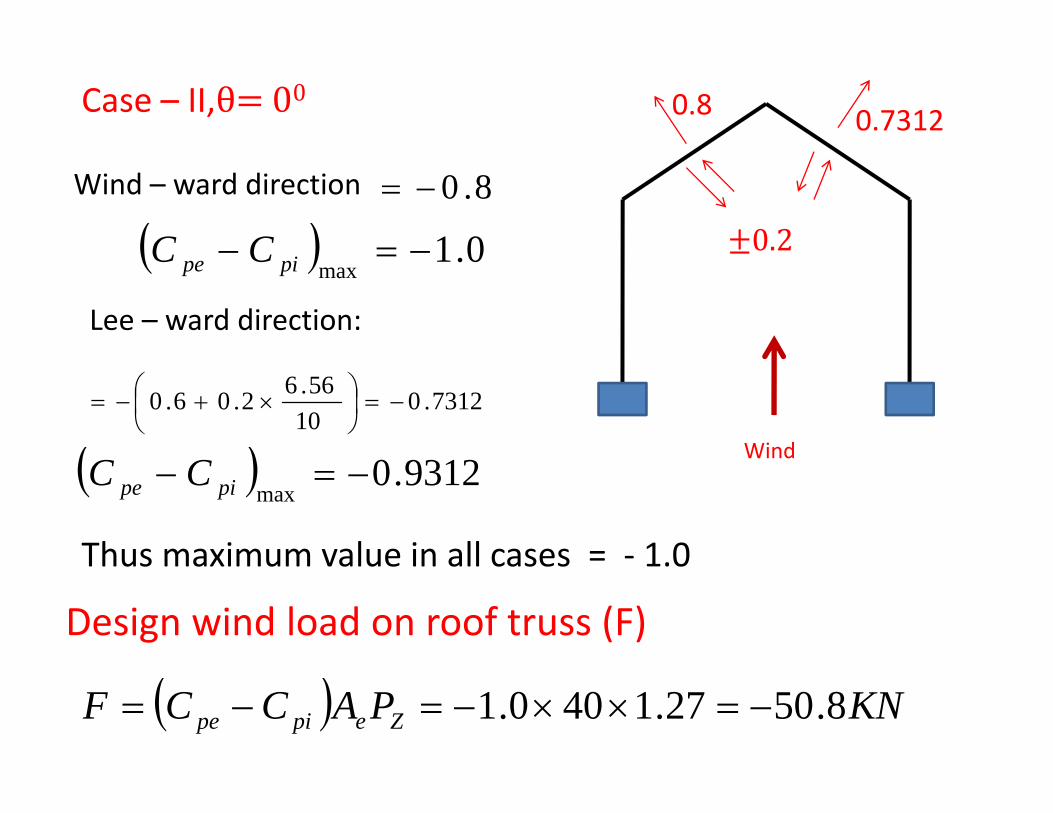
Case – II, 00.73120.8
Wind – ward direction 8.0−=
( ) 01−=− CC 0.2
Lee – ward direction:
( ) 0.1max
=pipe CC
( ) Wind
7312.01056.62.06.0 −=⎟
⎠⎞
⎜⎝⎛ ×+−=
( ) 9312.0max
−=− pipe CCWind
Thus maximum value in all cases = ‐ 1 0Thus maximum value in all cases = 1.0
Design wind load on roof truss (F)
( ) KNPACCF Zepipe 8.5027.1400.1 −=××−=−=
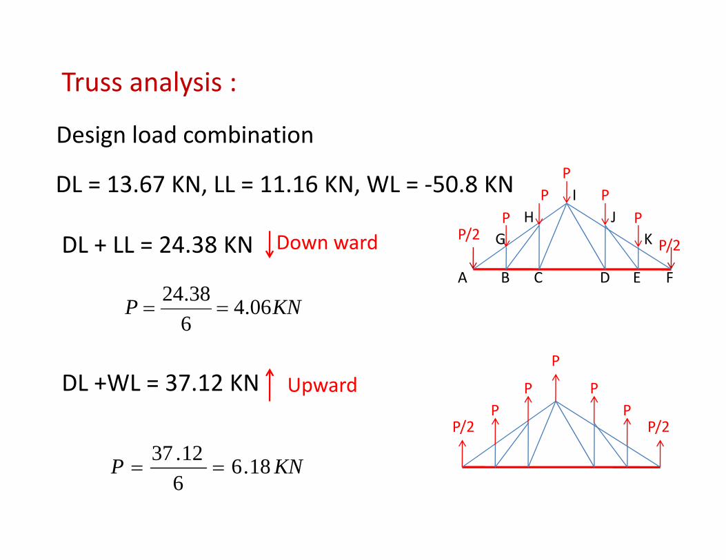
Truss analysis :
Design load combinationPDL = 13.67 KN, LL = 11.16 KN, WL = ‐50.8 KN
DL + LL = 24 38 KN Down ward
PP
PP
PP/2
P/2GH
IJ
KDL + LL = 24.38 KN Down ward P/2
KNP 06.438.24==
A B C D E F
DL +WL = 37 12 KN Upward P
P
P
6
DL +WL = 37.12 KN Upward
P/2 P/2P
P PP
1237 KNP 18.6612.37
==
sis:
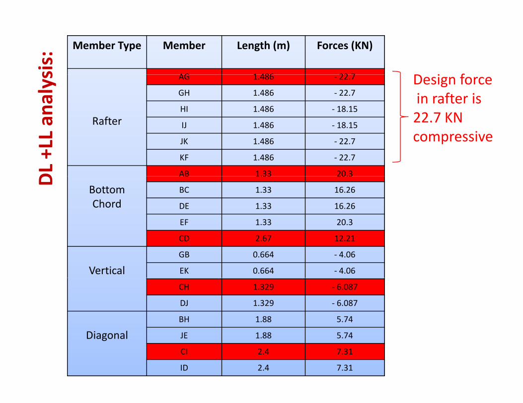
Member Type Member Length (m) Forces (KN)
AG 1 486 22 7 D i f
analys
Rafter
AG 1.486 ‐ 22.7
GH 1.486 ‐ 22.7
HI 1.486 ‐ 18.15
IJ 1 486 18 15
Design forcein rafter is 22.7 KN
DL +LL IJ 1.486 ‐ 18.15
JK 1.486 ‐ 22.7
KF 1.486 ‐ 22.7
AB 1.33 20.3
compressive
D
Bottom Chord
AB 1.33 20.3
BC 1.33 16.26
DE 1.33 16.26
EF 1.33 20.3
CD 2.67 12.21
VerticalGB 0.664 ‐ 4.06
EK 0.664 ‐ 4.06
CH 1.329 ‐ 6.087
DJ 1.329 ‐ 6.087
BH 1.88 5.74
Diagonal JE 1.88 5.74
CI 2.4 7.31
ID 2.4 7.31
sis:
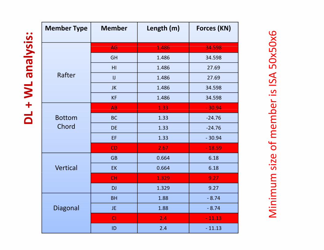
Member Type Member Length (m) Forces (KN)
AG 1 486 34 598 0x6
analys
Rafter
AG 1.486 34.598
GH 1.486 34.598
HI 1.486 27.69
IJ 1 486 27 69 A 50x50
+ WL a IJ 1.486 27.69
JK 1.486 34.598
KF 1.486 34.598
AB 1.33 ‐ 30.94 ber is ISA
DL Bottom
Chord
AB 1.33 30.94
BC 1.33 ‐24.76
DE 1.33 ‐24.76
EF 1.33 ‐ 30.94 mem
b
CD 2.67 ‐ 18.59
VerticalGB 0.664 6.18
EK 0.664 6.18 size of
CH 1.329 9.27
DJ 1.329 9.27
BH 1.88 ‐ 8.74 nimum
Diagonal JE 1.88 ‐ 8.74
CI 2.4 ‐ 11.13
ID 2.4 ‐ 11.13
Min
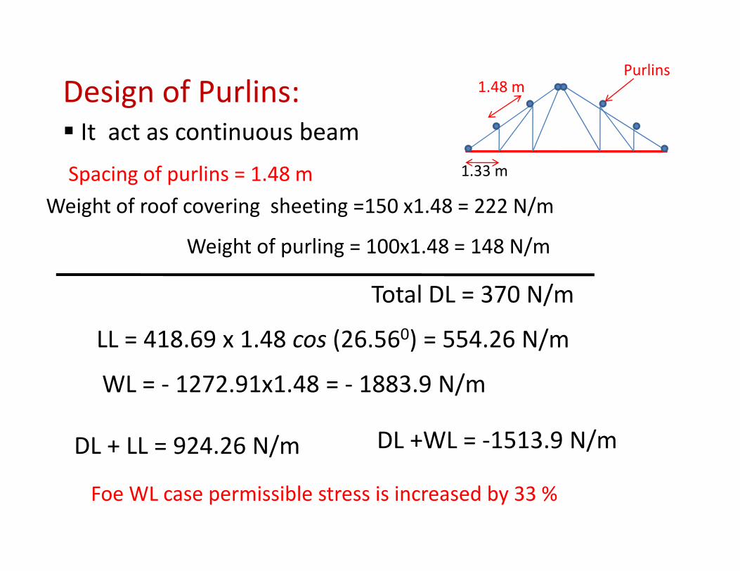
Design of Purlins: 1.48 mPurlins
g
Spacing of purlins = 1 48 m 1.33 m
It act as continuous beam
Spacing of purlins 1.48 mWeight of roof covering sheeting =150 x1.48 = 222 N/m
Weight of purling = 100x1 48 = 148 N/mWeight of purling = 100x1.48 = 148 N/m
Total DL = 370 N/m
LL = 418.69 x 1.48 cos (26.560) = 554.26 N/m
WL = ‐ 1272.91x1.48 = ‐ 1883.9 N/m/
DL + LL = 924.26 N/m DL +WL = ‐1513.9 N/m
Foe WL case permissible stress is increased by 33 %
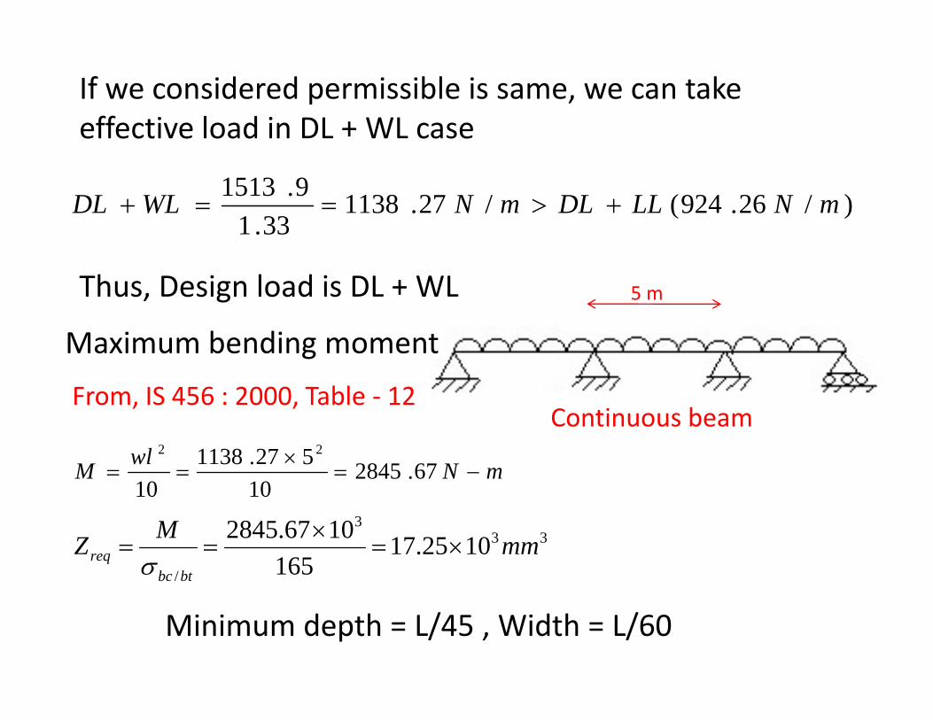
If we considered permissible is same, we can take effective load in DL + WL caseeffective load in DL + WL case
)/26.924(/27.1138331
9.1513 mNLLDLmNWLDL +>==+33.1
Thus, Design load is DL + WL 5 m
Maximum bending moment
From, IS 456 : 2000, Table ‐ 12Continuous beam
mNwlM −=×
== 67.284510
527.113810
22
, ,
1010
333
/
1025.17165
1067.2845 mmMZbtbc
req ×=×
==σ
Minimum depth = L/45 , Width = L/60
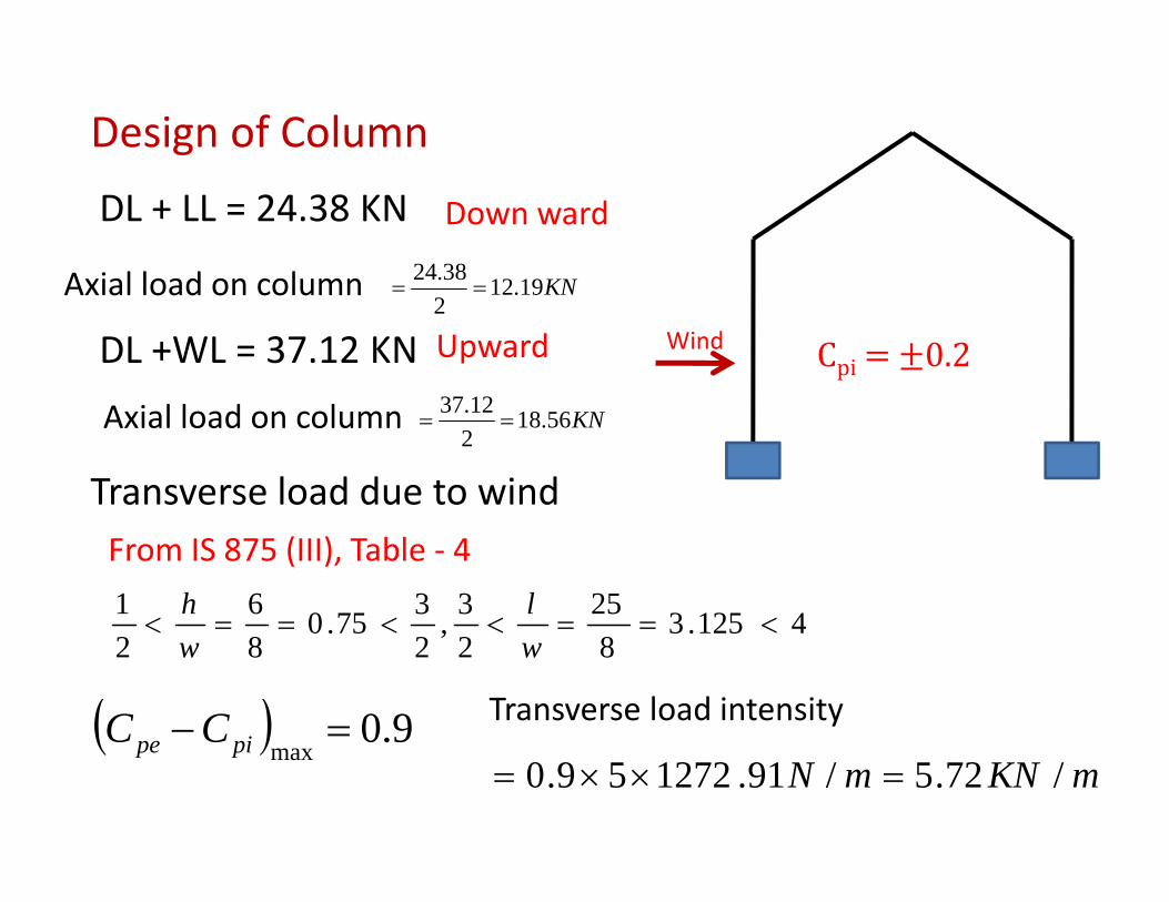
Design of Column
DL + LL = 24.38 KN Down ward
Axial load on column KN191238.24
WindDL +WL = 37.12 KN Upward
Axial load on column KN19.122
==
Cpi 0.2
Axial load on column KN56.18212.37
==
Transverse load due to windFrom IS 875 (III), Table ‐ 4
41253253375061<==<<==<
lh 4125.382
,2
75.082
<==<<==<ww
( ) 90=−CC Transverse load intensity ( ) 9.0max
=pipe CCmKNmN /72.5/91.127259.0 =××=
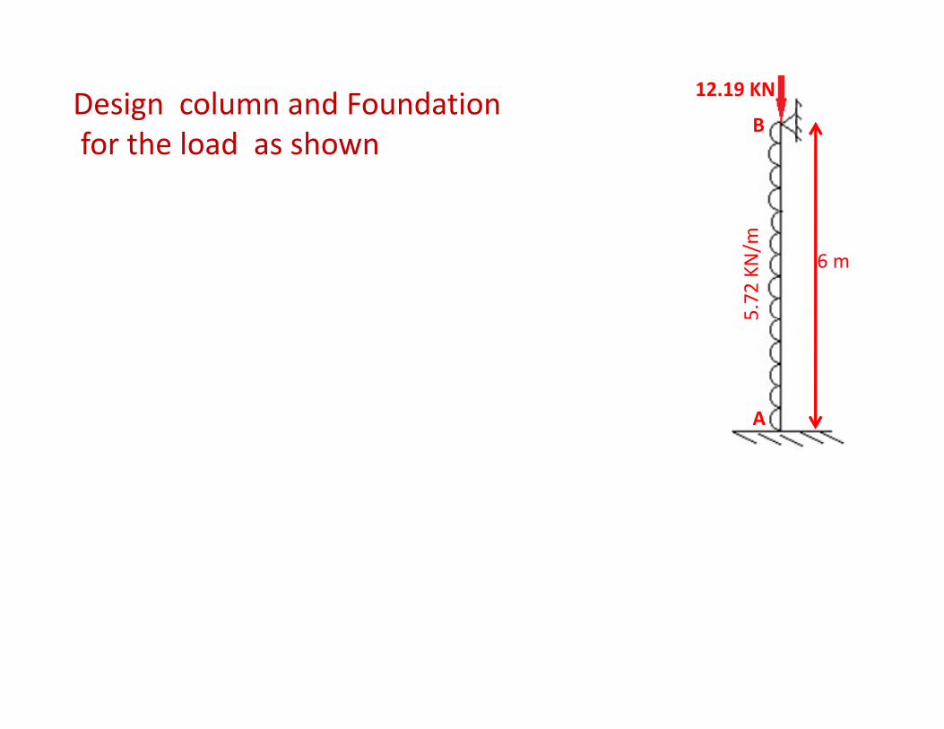
12.19 KN
BDesign column and Foundation f th l d hfor the load as shown
6 m
5.72
KN/m
5
A
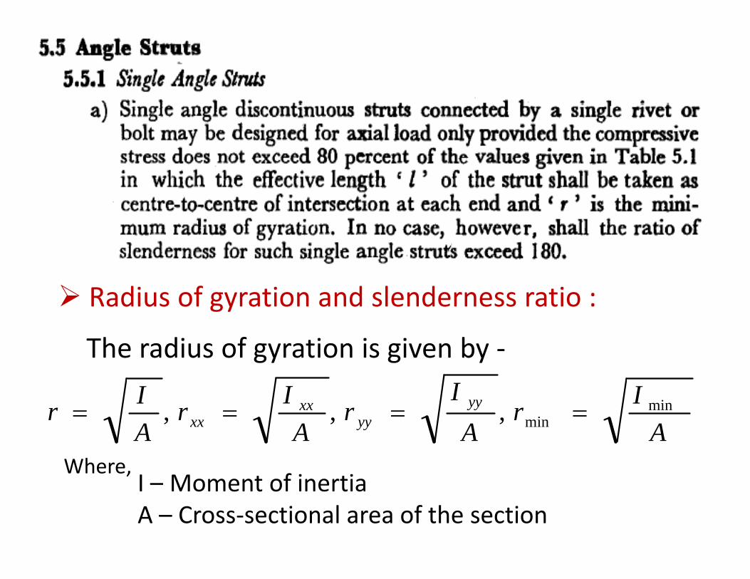
Radius of gyration and slenderness ratio :
The radius of gyration is given by ‐
IIIIA
IrA
Ir
AIr
AIr yy
yyxx
xxmin
min,,, ====
Where,Where,I – Moment of inertiaA – Cross‐sectional area of the section