Especificaciones por producto FLIR ONE Pro LT FLIR ONE Pro ...

Design of Columnsg
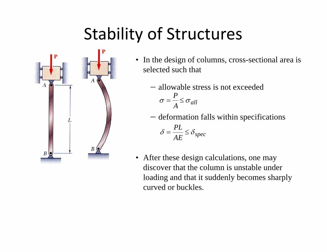
Stability of Structures• In the design of columns, cross-sectional area is
selected such that
− allowable stress is not exceeded
allAP σσ ≤=
− deformation falls within specifications
specAEPL δδ ≤=
• After these design calculations, one may discover that the column is unstable under loading and that it suddenly becomes sharply curved or buckles.
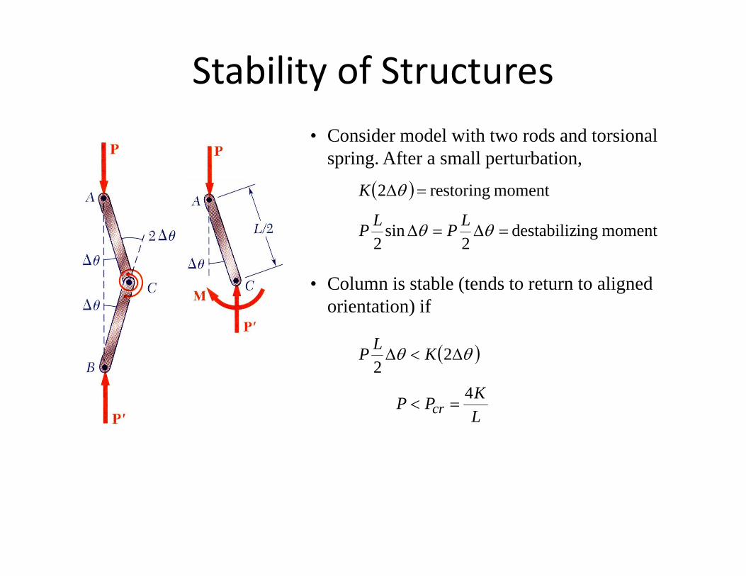
Stability of Structures• Consider model with two rods and torsional
spring. After a small perturbation,
( )
moment ingdestabiliz 2
sin2
moment restoring 2
=∆=∆
=∆
θθ
θ
LPLP
K
• Column is stable (tends to return to aligned orientation) if
( )
K
KLP
4
22
∆<∆ θθ
LKPP cr
4=<
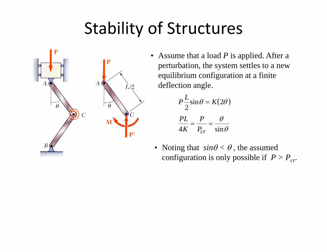
Stability of Structures• Assume that a load P is applied. After a
perturbation, the system settles to a new equilibrium configuration at a finite q gdeflection angle.
( )θθ 2sin2
= KLP
θθ
sin4==
crPP
KPL
• Noting that sinθ < θ , the assumed configuration is only possible if P > Pcr.
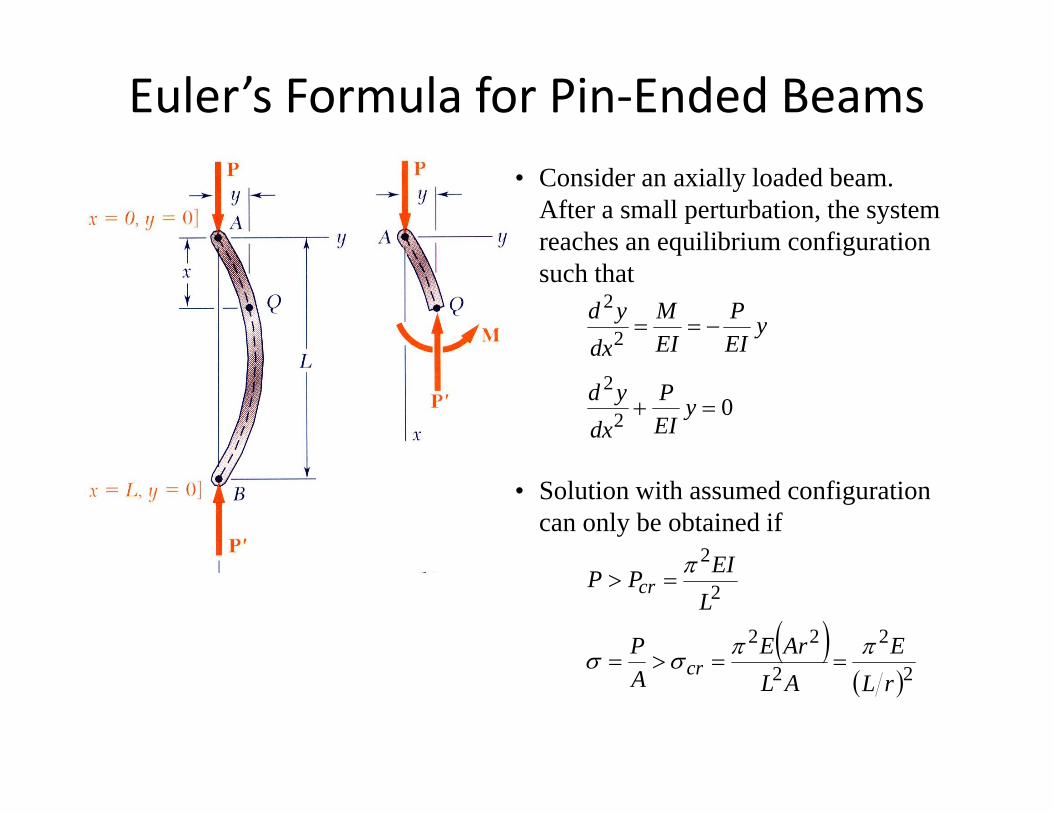
Euler’s Formula for Pin‐Ended Beams• Consider an axially loaded beam.
After a small perturbation, the system reaches an equilibrium configuration q gsuch that
2
2−== y
EIP
EIM
dxyd
02
2=+ y
EIP
dxyd
dx
• Solution with assumed configuration can only be obtained if
2EI
( ) 222
2
2
EArEP
LEIPP cr
ππσσ
π
==>=
=>
( )( )22 rLALA crσσ ==>=
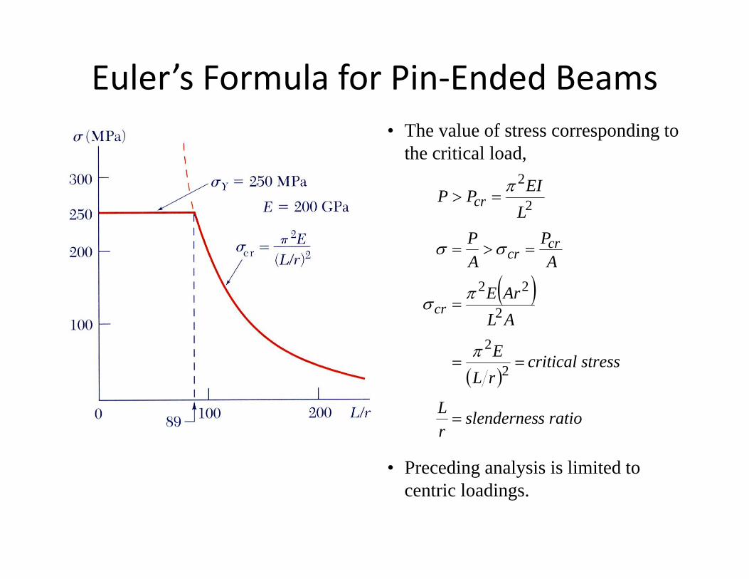
Euler’s Formula for Pin‐Ended Beams
EI2
• The value of stress corresponding to the critical load,
PPL
EIPP
crcr
cr 2
2
=>=
=>
σσ
π
( )ALArE
AA
cr
cr
2
22=
>
πσ
σσ
( )tresscritical s
rLE 2
2==
π
s ratioslendernesrL =
• Preceding analysis is limited toPreceding analysis is limited to centric loadings.
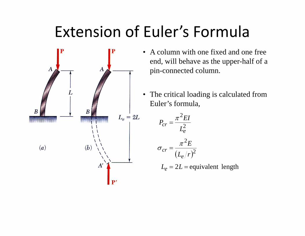
Extension of Euler’s Formula• A column with one fixed and one free
end, will behave as the upper-half of a pin-connected column.p
• The critical loading is calculated from Euler’s formulaEuler s formula,
2
2=
LEIPe
crπ
( )22
=rLE
ecr
πσ
length equivalent 2 == LLe
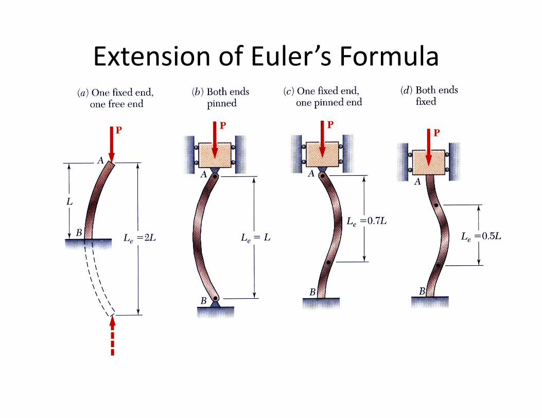
Extension of Euler’s Formula
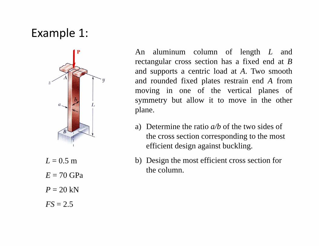
Example 1:An aluminum column of length L andrectangular cross section has a fixed end at Band supports a centric load at A. Two smoothand rounded fixed plates restrain end A frommoving in one of the vertical planes ofsymmetry but allow it to move in the other
lplane.
a) Determine the ratio a/b of the two sides of the cross section corresponding to the mostthe cross section corresponding to the most efficient design against buckling.
b) Design the most efficient cross section for the column
L = 0.5 mthe column.E = 70 GPa
P = 20 kN
FS = 2.5
SOLUTION TO EXAMPLE 1SOLUTION TO EXAMPLE 1:
The most efficient design occurs when theresistance to buckling is equal in both planes of
• Buckling in xy plane:
symmetry. This occurs when the slendernessratios are equal.
g y p
70
1212
23121
2
LL
araabba
AIr z
zz ====
127.0,
aL
rL
z
ze =
• Buckling in xz plane:
• Most efficient design:,, =
rL
rL
y
ye
z
ze
g p
2
1212
23121
2
LL
brbabab
AI
r yy
y ====
70
12/2
127.0
=b
La
L
y
12/2,
bL
rL
y
ye =27.0
=ba
35.0=ba
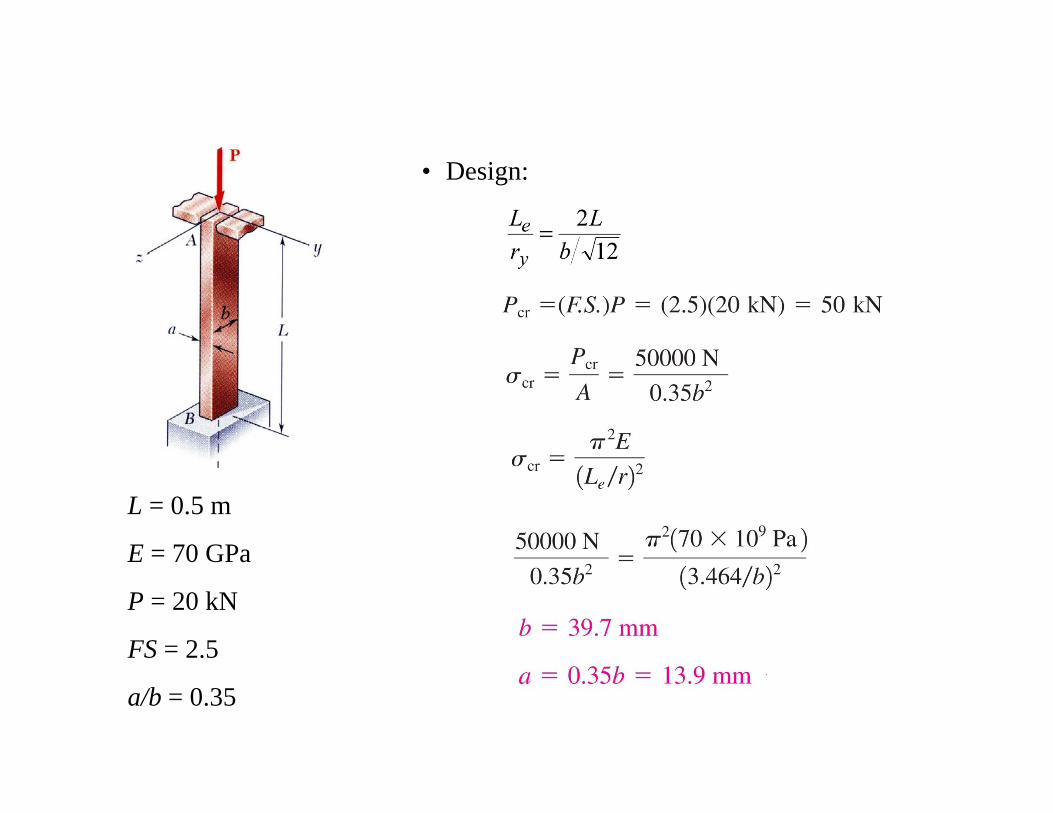
• Design:
L = 0.5 m
E = 70 GPaE 70 GPa
P = 20 kN
FS = 2.5
a/b = 0.35
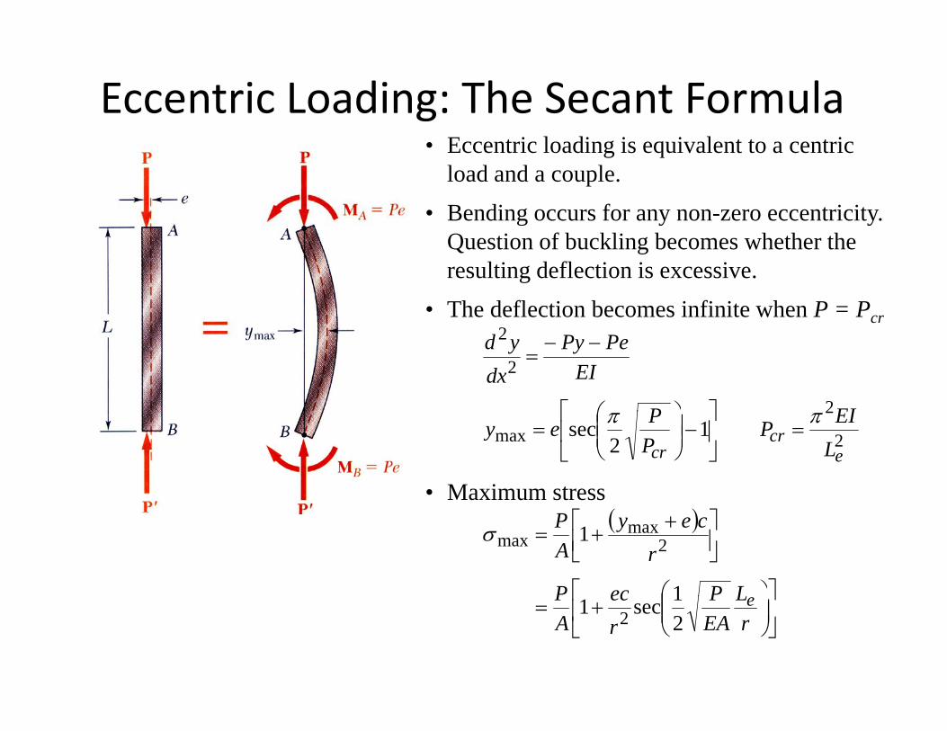
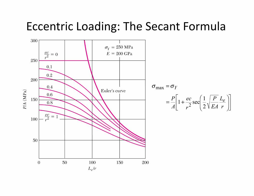
Eccentric Loading: The Secant Formula• Eccentric loading is equivalent to a centric
load and a couple.• Bending occurs for any non-zero eccentricity.
Question of buckling becomes whether the resulting deflection is excessive.
• The deflection becomes infinite when P = Pcr
2
2
2
EIP
EIPePy
dxyd
⎤⎡ ⎞⎛
−−=
cr
2
2max 1
2sec
ecr
cr LEIP
PPey ππ
=⎥⎦
⎤⎢⎣
⎡−⎟⎟
⎠
⎞⎜⎜⎝
⎛=
• Maximum stress( )
⎤⎡ ⎞⎜⎛
⎥⎦⎤
⎢⎣⎡ ++=
LPecP
rcey
AP
1
1 2max
maxσ
⎥⎦
⎤⎢⎣
⎡⎟⎠
⎞⎜⎜⎝
⎛+=
rL
EAP
rec
AP e
21sec1 2
Eccentric Loading: The Secant Formula
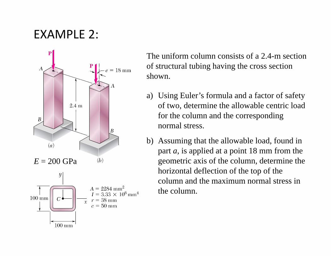
EXAMPLE 2:
The uniform column consists of a 2.4-m section of structural tubing having the cross section shown.
a) Using Euler’s formula and a factor of safety of two, determine the allowable centric load for the column and the corresponding normal stress.
b) Assuming that the allowable load, found in ) g ,part a, is applied at a point 18 mm from the geometric axis of the column, determine the horizontal deflection of the top of the
E = 200 GPa
column and the maximum normal stress in the column.
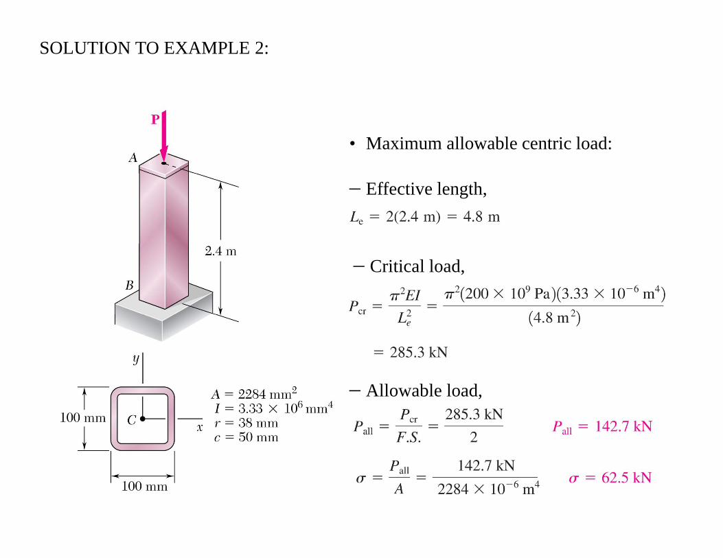
SOLUTION TO EXAMPLE 2:
• Maximum allowable centric load:
− Effective length,
− Critical load,
All bl l d− Allowable load,
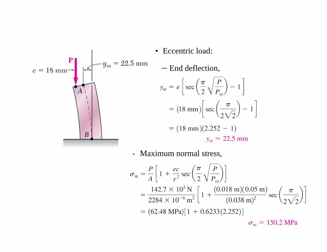
• Eccentric load:
− End deflection,
- Maximum normal stress,
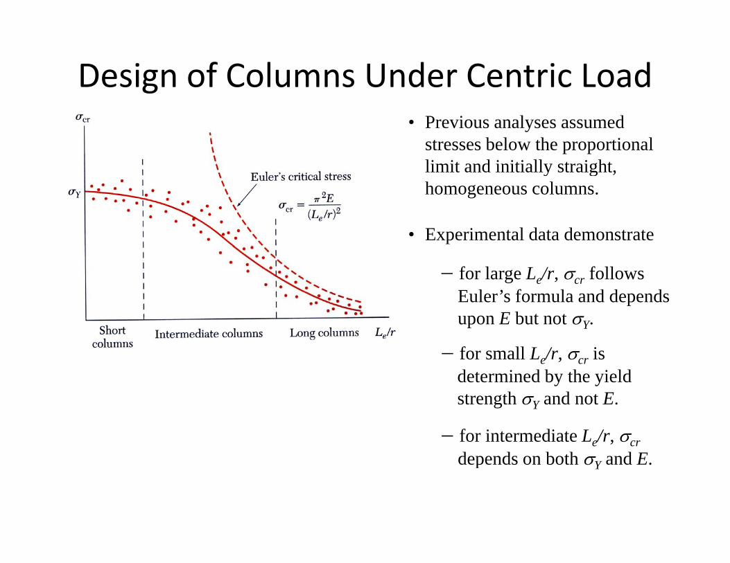
Design of Columns Under Centric Load• Previous analyses assumed
stresses below the proportional limit and initially straight, y g ,homogeneous columns.
• Experimental data demonstrate
− for large Le/r, σcr follows Euler’s formula and depends upon E but not σupon E but not σY.
− for small Le/r, σcr is determined by the yield
− for intermediate Le/r, σcrdepends on both σ and E
strength σY and not E.
depends on both σY and E.
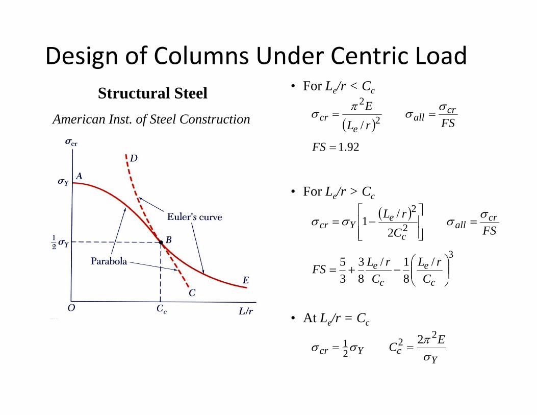
Design of Columns Under Centric LoadStructural Steel
American Inst. of Steel Construction
• For Le/r < Cc
( )/ 2
2==
FSrLE cr
alle
crσσπσ
( )92.1
/
=FS
rLe
• For Le/r > Cc
( )2
2
2/1 =
⎥⎥⎦
⎤
⎢⎢⎣
⎡−= cr
alle
Ycr FSCrL σσσσ
3/
81/
83
35
2
⎟⎟⎠
⎞⎜⎜⎝
⎛−+=
⎥⎦⎢⎣
c
e
c
e
c
CrL
CrLFS
FSC
⎠⎝
• At Le/r = Cc
Eπ 22 2
YcYcr
ECσπσσ 2
21 2
==
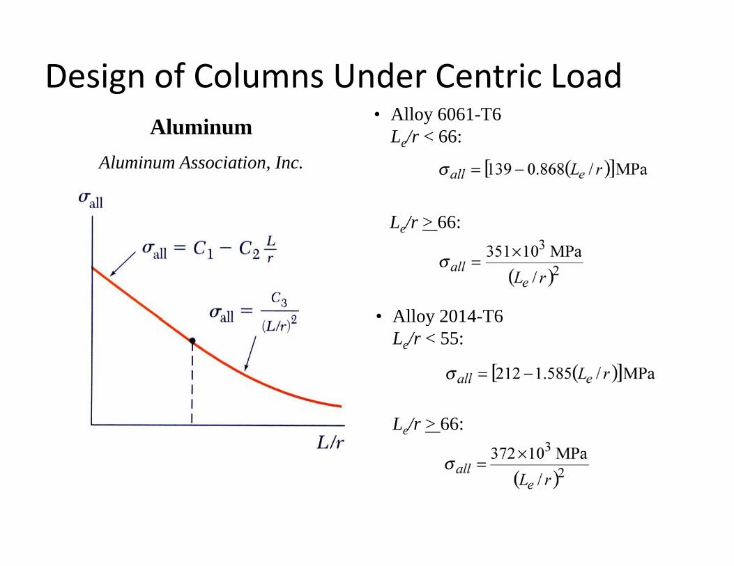
Design of Columns Under Centric LoadAluminum
Aluminum Association, Inc.
• Alloy 6061-T6Le/r < 66:
Le/r > 66:
• Alloy 2014-T6Alloy 2014 T6Le/r < 55:
Le/r > 66:
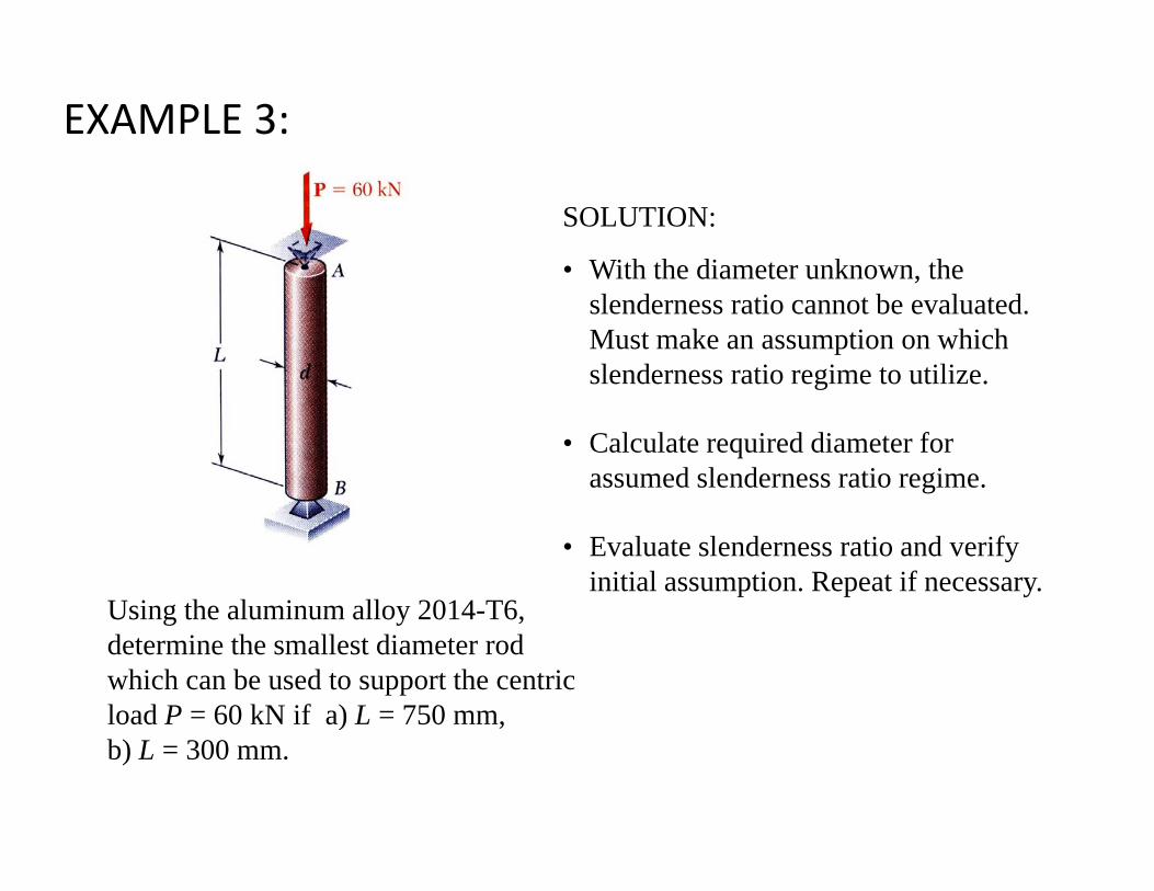
EXAMPLE 3:
SOLUTION:
• With the diameter unknown, theWith the diameter unknown, the slenderness ratio cannot be evaluated. Must make an assumption on which slenderness ratio regime to utilize.g
• Calculate required diameter for assumed slenderness ratio regime.
Using the aluminum alloy 2014-T6
• Evaluate slenderness ratio and verify initial assumption. Repeat if necessary.
Using the aluminum alloy 2014 T6, determine the smallest diameter rod which can be used to support the centric load P = 60 kN if a) L = 750 mm, ) ,b) L = 300 mm.
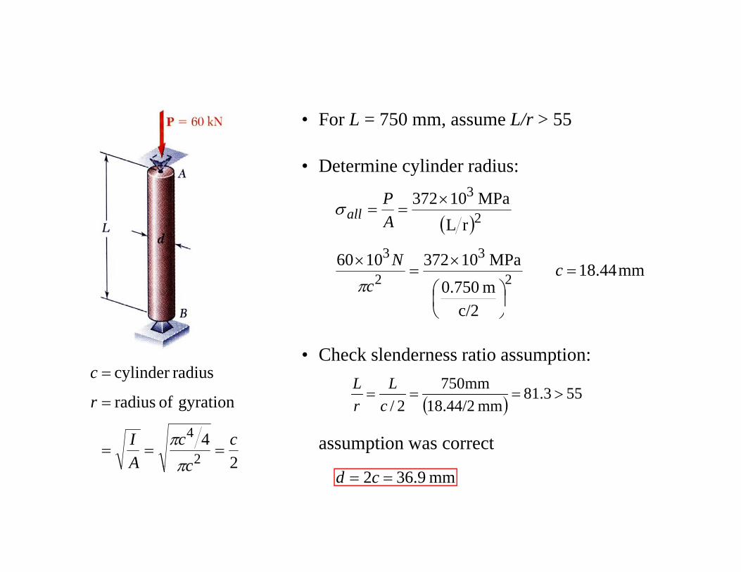
• For L = 750 mm, assume L/r > 55
• Determine cylinder radius:
( )rLMPa 10372
33
2
3×==
AP
allσ
mm44.18
c/2m 0.750MPa 103721060
2
3
2
3=
⎟⎠⎞
⎜⎝⎛
×=
× cc
Nπ
radiuscylinder c =• Check slenderness ratio assumption:
55381mm750>===
LL
24
gyration of radius
2
4 cc
cAI
r
===
=
ππ
( ) 553.81mm 18.44/22/
>===cr
assumption was correct2cA π
mm9.362 == cd
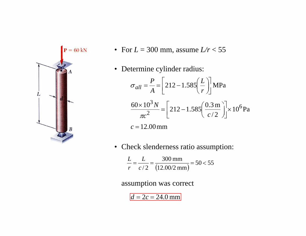
• For L = 300 mm, assume L/r < 55
• Determine cylinder radius:
301060
MPa 585.1212
3 ⎤⎡ ⎞⎛
⎥⎦⎤
⎢⎣⎡
⎟⎠⎞
⎜⎝⎛−==
N
rL
AP
allσ
mm00.12
Pa102/m3.0585.12121060 6
2
3
=
×⎥⎦⎤
⎢⎣⎡
⎟⎠⎞
⎜⎝⎛−=
×
c
ccN
π
• Check slenderness ratio assumption:
5550mm 003<===
LL( ) 5550
mm 12.00/22/<===
cr
assumption was correct
mm0.242 == cd
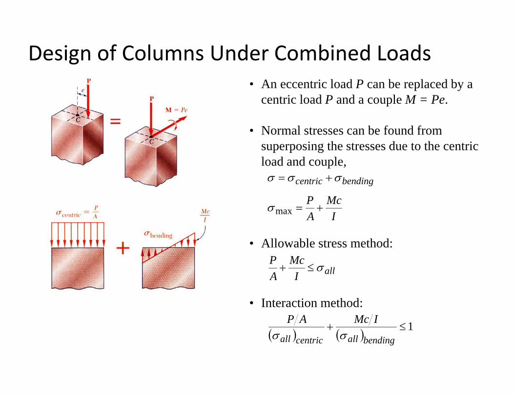
Design of Columns Under Combined Loads• An eccentric load P can be replaced by a
centric load P and a couple M = Pe.
• Normal stresses can be found from superposing the stresses due to the centric load and couple,
IMc
AP
bendingcentric
+=
+=
maxσ
σσσ
• Allowable stress method:
allIMc
AP σ≤+ allIA
• Interaction method:
1≤IMcAP( ) ( ) 1≤+
bendingallcentricall σσ

THANK YOU!!