DESIGN OF A STEEL FOOT OVER BRIDGE IN A RAILWAY · PDF fileANALYSIS BY STAAD.PRO - STRUCTURAL...
16
http://www.iaeme.com/IJCIET/index.asp 1533 [email protected] International Journal of Civil Engineering and Technology (IJCIET) Volume 8, Issue 8, August 2017, pp. 1533–1548, Article ID: IJCIET_08_08_167 Available online at http://http://www.iaeme.com/ijciet/issues.asp?JType=IJCIET&VType=8&IType=8 ISSN Print: 0976-6308 and ISSN Online: 0976-6316 © IAEME Publication Scopus Indexed DESIGN OF A STEEL FOOT OVER BRIDGE IN A RAILWAY STATION S. Rajesh Department of Civil Engineering BIHER, Bharath University ABSTRACT Civil engineering deals with the design, construction and maintenance of physical and naturally built environment, including works like bridges, roads, canals, dams and buildings. It is the oldest and broadest engineering profession. All the engineering specialties have been derived from civil engineering. It is divided into various sub disciplines including environmental engineering, geotechnical engineering, structural engineering, transportation engineering, material engineering, surveying and construction engineering. The principles of all the above engineering aspects are applied to the residential, commercial, industrial and public works projects of all sizes and levels of construction. Keyword: Bridge, Railway Station Cite this Article: S. Rajesh, Design of A Steel Foot Over Bridge In A Railway Station, International Journal of Civil Engineering and Technology, 8(8), 2017, pp. 1533–1548. http://www.iaeme.com/IJCIET/issues.asp?JType=IJCIET&VType=8&IType=8 1. OBJECTIVES 1. To analyse and design a Foot Over Bridge at a railway station in a metropolitan city. 2. To design a light weight structure with maximum strength, durability and safety factor. 3. To make use of a simple and effective design methodology and construction. The design procedure and methodology adopted is to be in conformance to the present methodology being used in the industry. 4. To analyze the structure using STAAD. Pro for the various loads acting on the structure. 5. To meet the requirements of the codal provisions given in the codes, being considered and try to adopt economical sections in the structure. 6. To make detailed drawings indicating the sections used for the various components 2. METHODOLOGY 1. Collection of details and information about analysis and design of steel structural elements and current practices in the industry.
-
Upload
nguyentram -
Category
Documents
-
view
259 -
download
9
Transcript of DESIGN OF A STEEL FOOT OVER BRIDGE IN A RAILWAY · PDF fileANALYSIS BY STAAD.PRO - STRUCTURAL...
http://www.iaeme.com/IJCIET/index.asp 1533 [email protected]
International Journal of Civil Engineering and Technology (IJCIET) Volume 8, Issue 8, August 2017, pp. 1533–1548, Article ID: IJCIET_08_08_167
Available online at http://http://www.iaeme.com/ijciet/issues.asp?JType=IJCIET&VType=8&IType=8
ISSN Print: 0976-6308 and ISSN Online: 0976-6316
© IAEME Publication Scopus Indexed
DESIGN OF A STEEL FOOT OVER BRIDGE IN A
RAILWAY STATION
S. Rajesh
Department of Civil Engineering BIHER, Bharath University
ABSTRACT
Civil engineering deals with the design, construction and maintenance of physical
and naturally built environment, including works like bridges, roads, canals, dams
and buildings. It is the oldest and broadest engineering profession. All the engineering
specialties have been derived from civil engineering. It is divided into various sub
disciplines including environmental engineering, geotechnical engineering, structural
engineering, transportation engineering, material engineering, surveying and
construction engineering. The principles of all the above engineering aspects are
applied to the residential, commercial, industrial and public works projects of all sizes
and levels of construction.
Keyword: Bridge, Railway Station
Cite this Article: S. Rajesh, Design of A Steel Foot Over Bridge In A Railway
Station, International Journal of Civil Engineering and Technology, 8(8), 2017,
pp. 1533–1548.
http://www.iaeme.com/IJCIET/issues.asp?JType=IJCIET&VType=8&IType=8
1. OBJECTIVES
1. To analyse and design a Foot Over Bridge at a railway station in a metropolitan city.
2. To design a light weight structure with maximum strength, durability and safety
factor.
3. To make use of a simple and effective design methodology and construction. The
design procedure and methodology adopted is to be in conformance to the present
methodology being used in the industry.
4. To analyze the structure using STAAD. Pro for the various loads acting on the
structure.
5. To meet the requirements of the codal provisions given in the codes, being considered
and try to adopt economical sections in the structure.
6. To make detailed drawings indicating the sections used for the various components
2. METHODOLOGY
1. Collection of details and information about analysis and design of steel structural
elements and current practices in the industry.
S.Rajesh
http://www.iaeme.com/IJCIET/index.asp 1534 [email protected]
2. Review of literature and study of examples for the proposed project.
3. Study of codal provisions for Design of steel structures, loading details.
4. Selection of site and collection of site information from previously completed projects
and concerned authorities.
5. Preparation of plan and elevation of the structure using AUTOCAD.
6. Making the models of the various components in STAAD and assigning member and
material properties as per the design.
7. Loading the structure elements for Dead Loads, Imposed Loads and Wind Loads as
per the Indian Railway Standard – Steel Bridge code.
8. Design of structural components of the foot over bridge for the loading details
acquired from STAAD model.
9. Design of the appropriate foundation for the loading details.
10. Preparation of detailed design drawings.
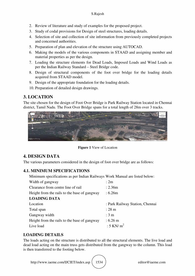
3. LOCATION
The site chosen for the design of Foot Over Bridge is Park Railway Station located in Chennai
district, Tamil Nadu. The Foot Over Bridge spans for a total length of 28m over 3 tracks.
Figure 1 View of Location
4. DESIGN DATA
The various parameters considered in the design of foot over bridge are as follows:
4.1. MINIMUM SPECIFICATIONS
Minimum specifications as per Indian Railways Work Manual are listed below:
Width of gangway : 2m
Clearance from centre line of rail : 2.36m
Height from the rails to the base of gangway : 6.26m
LOADING DATA
Location : Park Railway Station, Chennai
Total span : 28 m
Gangway width : 3 m
Height from the rails to the base of gangway : 6.26 m
Live load : 5 KN/ m2
LOADING DETAILS
The loads acting on the structure is distributed to all the structural elements. The live load and
dead load acting on the main truss gets distributed from the gangway to the column. This load
is then transferred to the footing below.
Design of A Steel Foot Over Bridge In A Railway Station
http://www.iaeme.com/IJCIET/index.asp 1535 [email protected]
4.2. MATERIAL PROPERTIES
STEEL
1) Structural steel used in this design confirms to IS 2062 with the following properties:
Yield stress : 250 Mpa
Ultimate stress : 410 Mpa
2) HYSD reinforcement of grade Fe 415 confirming to IS 1786 is used throughout.
CONCRETE
All components unless specified in design : M20 grade
Characteristic compressive strength fck : 20 N/mm2
4.3. ANALYSIS BY STAAD.PRO - STRUCTURAL SOFTWARE
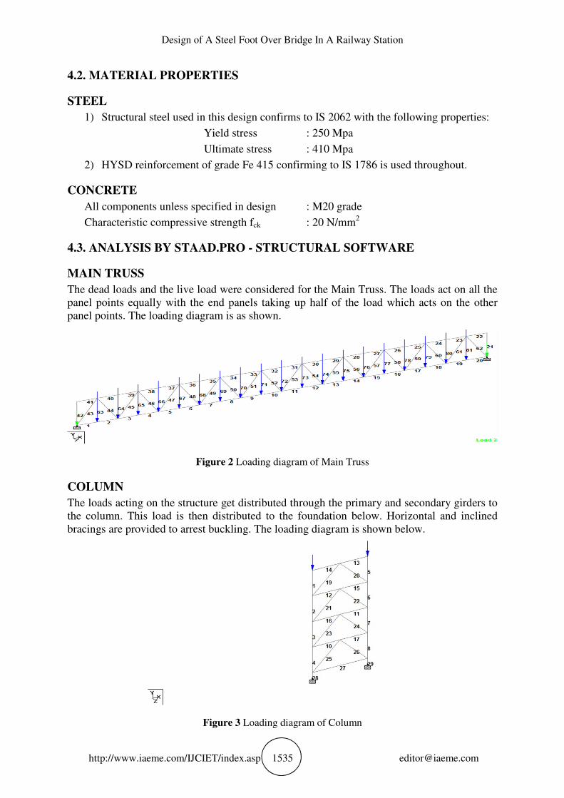
MAIN TRUSS
The dead loads and the live load were considered for the Main Truss. The loads act on all the
panel points equally with the end panels taking up half of the load which acts on the other
panel points. The loading diagram is as shown.
Figure 2 Loading diagram of Main Truss
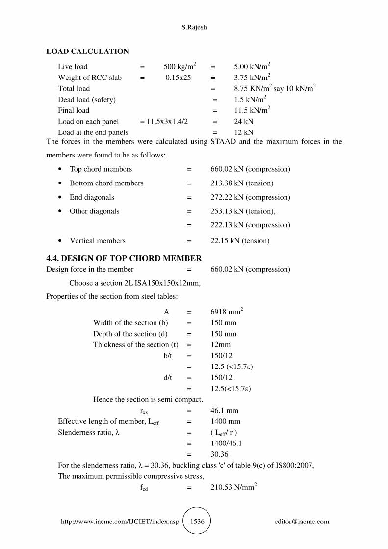
COLUMN
The loads acting on the structure get distributed through the primary and secondary girders to
the column. This load is then distributed to the foundation below. Horizontal and inclined
bracings are provided to arrest buckling. The loading diagram is shown below.
Figure 3 Loading diagram of Column
S.Rajesh
http://www.iaeme.com/IJCIET/index.asp 1536 [email protected]
LOAD CALCULATION
Live load = 500 kg/m2
= 5.00 kN/m2
Weight of RCC slab = 0.15x25 = 3.75 kN/m2
Total load = 8.75 KN/m2
say 10 kN/m2
Dead load (safety) = 1.5 kN/m
2
Final load = 11.5 kN/m2
Load on each panel = 11.5x3x1.4/2 = 24 kN
Load at the end panels = 12 kN
The forces in the members were calculated using STAAD and the maximum forces in the
members were found to be as follows:
• Top chord members = 660.02 kN (compression)
• Bottom chord members = 213.38 kN (tension)
• End diagonals = 272.22 kN (compression)
• Other diagonals = 253.13 kN (tension),
= 222.13 kN (compression)
• Vertical members = 22.15 kN (tension)
4.4. DESIGN OF TOP CHORD MEMBER
Design force in the member = 660.02 kN (compression)
Choose a section 2L ISA150x150x12mm,
Properties of the section from steel tables:
A = 6918 mm2
Width of the section (b) = 150 mm
Depth of the section (d) = 150 mm
Thickness of the section (t) = 12mm
b/t = 150/12
= 12.5 (<15.7ε)
d/t = 150/12
= 12.5(<15.7ε)
Hence the section is semi compact.
rxx = 46.1 mm
Effective length of member, Leff = 1400 mm
Slenderness ratio, λ = ( Leff/ r )
= 1400/46.1
= 30.36
For the slenderness ratio, λ = 30.36, buckling class 'c' of table 9(c) of IS800:2007,
The maximum permissible compressive stress,
fcd = 210.53 N/mm2
Design of A Steel Foot Over Bridge In A Railway Station
http://www.iaeme.com/IJCIET/index.asp 1537 [email protected]
Load carrying capacity = fcd x A
= 210.53 x 6918
= 1456.4kN > 660.02 kN
Load carrying capacity of the member > Design force of the member
Check for deflection
Deflection = P L
AE
= 660.02 x 10³ x 1400
= 6918 x 2 x 105
= 0.667 mm < 5mm
Hence the section 2L ISA150x150x12mm is safe and maybe adopted.
4.5. DESIGN OF BOTTOM CHORD MEMBER
Design force in the member = 213.38 kN (tension)
Choose a section 2L ISA 150x150x12mm
Properties of the section:
A = 6918 mm2
rxx = 46.1 mm
According to Clause 6.2 of IS 800:2007,
Load carrying capacity = Ag fy / γm0
= 6918 x 250/ 1.1
= 1572.27 kN > 213.38 kN
Load carrying capacity of the member > Design force of the member
Check for deflection
Deflection = P L
AE
= 213.38x103
x 1400
= 6918 x 2 x 105
= 0.215 mm < 5mm
Hence the section 2L ISA150x150x12mm is safe and maybe adopted.
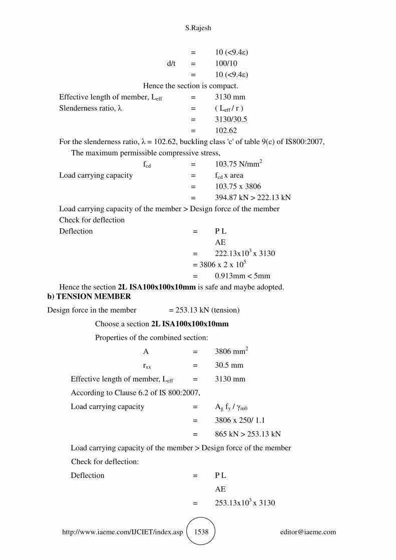
4.6. DESIGN OF INCLINED MEMBERS
a) COMPRESSION MEMBER
Design force in the member = 222.13 kN (compression)
Choose a section 2L100x100x10mm
Properties of the combined section:
A = 3806 mm2
rxx = 30.5 mm
Width of the section (b) = 100 mm
Depth of the section (d) = 100 mm
Thickness of the section (t) = 10 mm
b/t = 100/10
S.Rajesh
http://www.iaeme.com/IJCIET/index.asp 1538 [email protected]
= 10 (<9.4ε)
d/t = 100/10
= 10 (<9.4ε)
Hence the section is compact.
Effective length of member, Leff = 3130 mm
Slenderness ratio, λ = ( Leff / r )
= 3130/30.5
= 102.62
For the slenderness ratio, λ = 102.62, buckling class 'c' of table 9(c) of IS800:2007,
The maximum permissible compressive stress,
fcd = 103.75 N/mm2
Load carrying capacity = fcd x area
= 103.75 x 3806
= 394.87 kN > 222.13 kN
Load carrying capacity of the member > Design force of the member
Check for deflection
Deflection = P L
AE
= 222.13x103
x 3130
= 3806 x 2 x 105
= 0.913mm < 5mm
Hence the section 2L ISA100x100x10mm is safe and maybe adopted.
b) TENSION MEMBER
Design force in the member = 253.13 kN (tension)
Choose a section 2L ISA100x100x10mm
Properties of the combined section:
A = 3806 mm2
rxx = 30.5 mm
Effective length of member, Leff = 3130 mm
According to Clause 6.2 of IS 800:2007,
Load carrying capacity = Ag fy / γm0
= 3806 x 250/ 1.1
= 865 kN > 253.13 kN
Load carrying capacity of the member > Design force of the member
Check for deflection:
Deflection = P L
AE
= 253.13x103
x 3130
Design of A Steel Foot Over Bridge In A Railway Station
http://www.iaeme.com/IJCIET/index.asp 1539 [email protected]
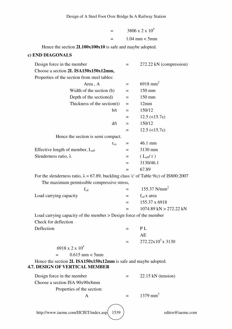
= 3806 x 2 x 105
= 1.04 mm < 5mm
Hence the section 2L100x100x10 is safe and maybe adopted.
c) END DIAGONALS
Design force in the member = 272.22 kN (compression)
Choose a section 2L ISA150x150x12mm,
Properties of the section from steel tables:
Area , A = 6918 mm2
Width of the section (b) = 150 mm
Depth of the section(d) = 150 mm
Thickness of the section(t) = 12mm
b/t = 150/12
= 12.5 (<15.7ε)
d/t = 150/12
= 12.5 (<15.7ε)
Hence the section is semi compact.
rxx = 46.1 mm
Effective length of member, Leff = 3130 mm
Slenderness ratio, λ = ( Leff/ r )
= 3130/46.1
= 67.89
For the slenderness ratio, λ = 67.89, buckling class 'c' of Table 9(c) of IS800:2007
The maximum permissible compressive stress,
fcd = 155.37 N/mm2
Load carrying capacity = fcd x area
= 155.37 x 6918
= 1074.89 kN > 272.22 kN
Load carrying capacity of the member > Design force of the member
Check for deflection
Deflection = P L
AE
= 272.22x103
x 3130
6918 x 2 x 105
= 0.615 mm < 5mm
Hence the section 2L ISA150x150x12mm is safe and maybe adopted.
4.7. DESIGN OF VERTICAL MEMBER
Design force in the member = 22.15 kN (tension)
Choose a section ISA 90x90x8mm
Properties of the section:
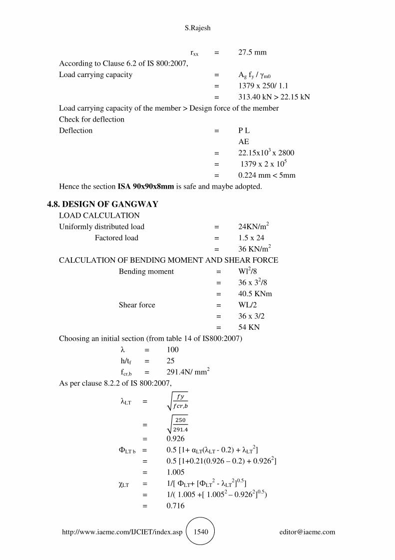
A = 1379 mm2
S.Rajesh
http://www.iaeme.com/IJCIET/index.asp 1540 [email protected]
rxx = 27.5 mm
According to Clause 6.2 of IS 800:2007,
Load carrying capacity = Ag fy / γm0
= 1379 x 250/ 1.1
= 313.40 kN > 22.15 kN
Load carrying capacity of the member > Design force of the member
Check for deflection
Deflection = P L
AE
= 22.15x103
x 2800
= 1379 x 2 x 105
= 0.224 mm < 5mm
Hence the section ISA 90x90x8mm is safe and maybe adopted.
4.8. DESIGN OF GANGWAY
LOAD CALCULATION
Uniformly distributed load = 24KN/m2
Factored load = 1.5 x 24
= 36 KN/m2
CALCULATION OF BENDING MOMENT AND SHEAR FORCE
Bending moment = Wl2/8
= 36 x 32/8
= 40.5 KNm
Shear force = WL/2
= 36 x 3/2
= 54 KN
Choosing an initial section (from table 14 of IS800:2007)
λ = 100
h/tf = 25
fcr,b = 291.4N/ mm2
As per clause 8.2.2 of IS 800:2007,
λLT = � �����,�
= � ����.�
= 0.926
ФLT b = 0.5 [1+ αLT(λLT - 0.2) + λLT2]
= 0.5 [1+0.21(0.926 – 0.2) + 0.9262]
= 1.005
χLT = 1/[ ФLT+ [ФLT2 - λLT
2]
0.5]
= 1/( 1.005 +[ 1.0052
– 0.9262]0.5
)
= 0.716
Design of A Steel Foot Over Bridge In A Railway Station
http://www.iaeme.com/IJCIET/index.asp 1541 [email protected]
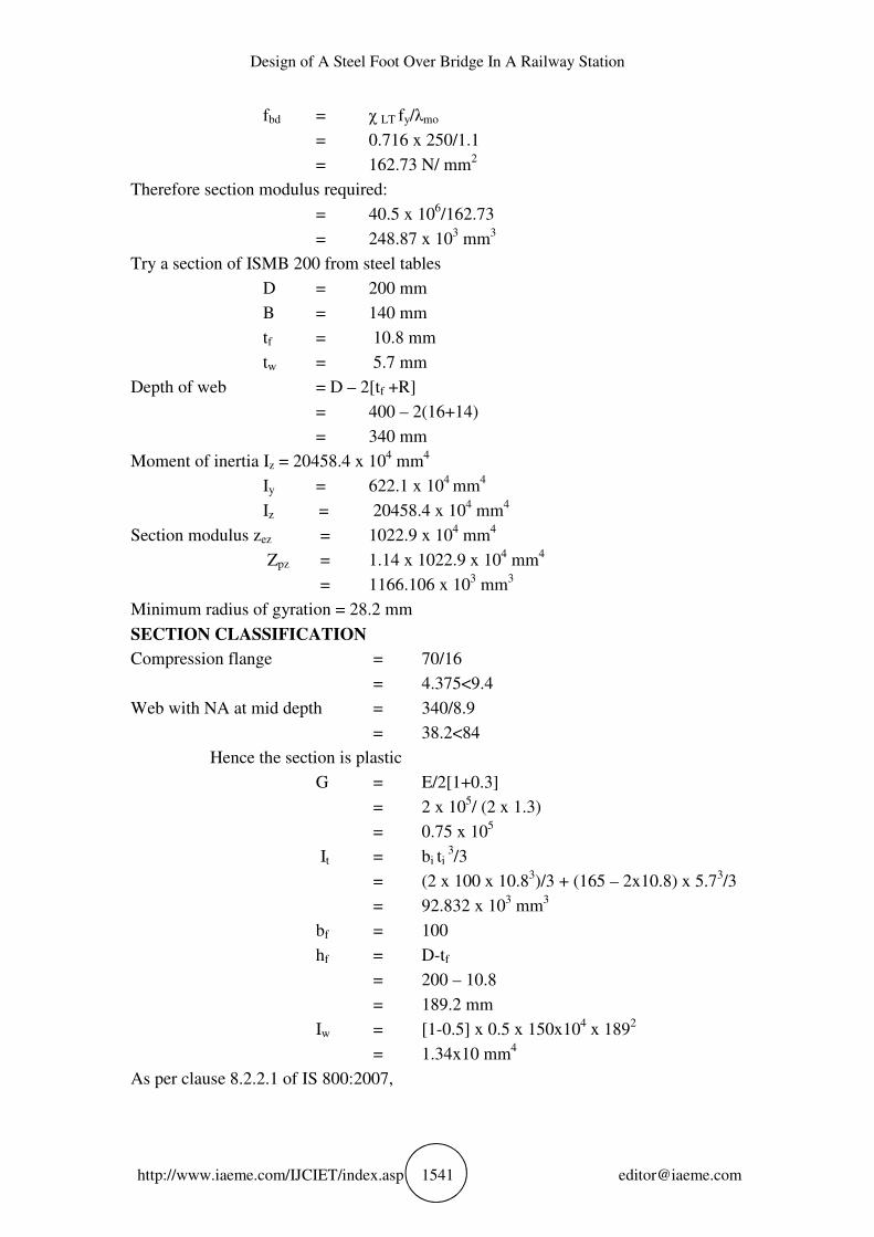
fbd = χ LT fy/λmo
= 0.716 x 250/1.1
= 162.73 N/ mm2
Therefore section modulus required:
= 40.5 x 10⁶/162.73
= 248.87 x 103 mm
3
Try a section of ISMB 200 from steel tables
D = 200 mm
B = 140 mm
tf = 10.8 mm
tw = 5.7 mm
Depth of web = D – 2[tf +R]
= 400 – 2(16+14)
= 340 mm
Moment of inertia Iz = 20458.4 x 104 mm
4
Iy = 622.1 x 10
4 mm
4
Iz = 20458.4 x 104 mm
4
Section modulus zez = 1022.9 x 104 mm
4
Zpz = 1.14 x 1022.9 x 104 mm
4
= 1166.106 x 103 mm
3
Minimum radius of gyration = 28.2 mm
SECTION CLASSIFICATION
Compression flange = 70/16
= 4.375<9.4
Web with NA at mid depth = 340/8.9
= 38.2<84
Hence the section is plastic
G = E/2[1+0.3]
= 2 x 10⁵/ (2 x 1.3)
= 0.75 x 10⁵
It = bi ti 3/3
= (2 x 100 x 10.83)/3 + (165 – 2x10.8) x 5.7
3/3
= 92.832 x 103 mm
3
bf = 100
hf = D-tf
= 200 – 10.8
= 189.2 mm
Iw = [1-0.5] x 0.5 x 150x104 x 189
2
= 1.34x10 mm4
As per clause 8.2.2.1 of IS 800:2007,
S.Rajesh
http://www.iaeme.com/IJCIET/index.asp 1542 [email protected]
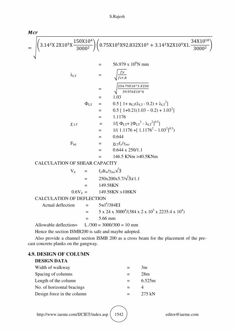
���= ��3.14�X 2X10X 150X10�3000� � �0.75X10X92.832X10! + 3.14�X2X10X1. 34X10�3000� �
= 56.979 x 10⁶N mm
λLT = � �����,�
= ���.#�$�^! $��.�#&$�^&
= 1.03
ФLT = 0.5 [ 1+ αLT(λLT - 0.2) + λLT2]
= 0.5 [ 1+0.21(1.03 – 0.2) + 1.032]
= 1.1176
χ LT = 1/[ ФLT+ [ФLT2 - λLT
2]
0.5]
= 1/( 1.1176 +[ 1.11762
– 1.032]0.5
)
= 0.644
Fbd = χLTfy/γmo
= 0.644 x 250/1.1
= 146.5 KNm >40.5KNm
CALCULATION OF SHEAR CAPACITY
Vd = fydtw/γmo√3
= 250x200x5.7/√3(1.1
= 149.58KN
0.6Vd = 149.58KN >108KN
CALCULATION OF DEFLECTION
Actual deflection = 5wl4/384EI
= 5 x 24 x 30004/(384 x 2 x 10
5 x 2235.4 x 10
4)
= 5.66 mm
Allowable deflection= L /300 = 3000/300 = 10 mm
Hence the section ISMB200 is safe and maybe adopted.
Also provide a channel section ISMB 200 as a cross beam for the placement of the pre-
cast concrete planks on the gangway.
4.9. DESIGN OF COLUMN
DESIGN DATA
Width of walkway = 3m
Spacing of columns = 28m
Length of the column = 6.525m
No. of horizontal bracings = 4
Design force in the column = 275 kN
Design of A Steel Foot Over Bridge In A Railway Station
http://www.iaeme.com/IJCIET/index.asp 1543 [email protected]
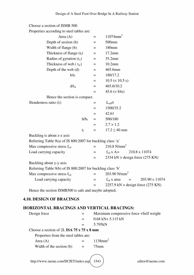
Choose a section of ISMB 500
Properties according to steel tables are:
Area (A) = 11074mm2
Depth of section (h) = 500mm
Width of flange (b) = 180mm
Thickness of flange (tf) = 17.2mm
Radius of gyration (ry) = 35.2mm
Thickness of web ( tw) = 10.2mm
Depth of the web (d) = 465.6mm
b/tf = 180/17.2
= 10.5 (< 10.5 ε)
d/tw = 465.6/10.2
= 45.6 (< 84ε)
Hence the section is compact.
Slenderness ratio (λ) = Leff/r
= 1500/35.2
= 42.61
h/bf = 500/180
= 2.7 > 1.2
tf = 17.2 ≤ 40 mm
Buckling is about z-z axis
Referring Table 9(a) of IS 800:2007 for buckling class ‘a’
Max compressive stress fcd = 210.8 N/mm2
Load carrying capacity = fcd x A = 210.8 x 11074
= 2334 kN > design force (275 KN)
Buckling about y-y axis
Referring Table 9(b) of IS 800:2007 for buckling class ‘b’
Max compressive stress fcd = 203.90 N/mm2
Load carrying capacity = fcd x area = 203.90 x 11074
= 2257.9 kN > design force (275 KN)
Hence the section ISMB500 is safe and maybe adopted.
4.10. DESIGN OF BRACINGS
HORIZONTAL BRACINGS AND VERTICAL BRACINGS:
Design force = Maximum compressive force +Self weight
= 0.68 kN+ 5.115 kN
= 5.795kN
Choose a section of 2L ISA 75 x 75 x 8 mm
Properties from the steel tables are:
Area (A) = 1138mm2
Width of the section (b) = 75mm

S.Rajesh
http://www.iaeme.com/IJCIET/index.asp 1544 [email protected]
Depth of the section (d) = 75mm
Thickness of the section (t) = 8mm
b/t = 75/8
= 9.3 (<9.4ε)
h/t = 75/8
= 9.3 (<9.4ε)
Hence the section is plastic.
For double angle = 2 x 1138
= 2276mm2
Radius of gyration (ry) = 22.8mm
Effective length (Leff) = 3m
Slenderness ratio (λ) = Leff/r
= 3000/22.8
= 131.57
Referring Table 9(c) of IS 800:2007 for buckling class ‘c’
Max compressive stress fcd = 72.9 N/mm2
Load carrying capacity = fcd x A
= 72.9 x 2276
= 165.9 kN > design force (5.795 kN)
Hence the section 2L ISA 75x75x8mm is safe and maybe adopted.
4.11. DESIGN OF FOOTING
DESIGN DATA
Assume square column as pedestal = 900x900mm
Load = 320kN
Safe bearing capacity = 190KN/m2
Depth of foundation = 1.8m
Use M20 grade concrete and Fe415 grade steel
SIZE OF FOOTING
P = 320kN
Qu = 190kN/m2
H = 1.8m
Pu = 320/190
= 1.6845m2
Minimum size of square footing = √1.6845
=1.29m
Assume a size of 1.4mx1.4m
THICKNESS OF FOOTING SLAB BASED ON SHEAR
QU = 320/0.25
= 1.28 N/m2
One way shear,
VU1 = 1.28 x 1400 x (250 – D)
Design of A Steel Foot Over Bridge In A Railway Station
http://www.iaeme.com/IJCIET/index.asp 1545 [email protected]
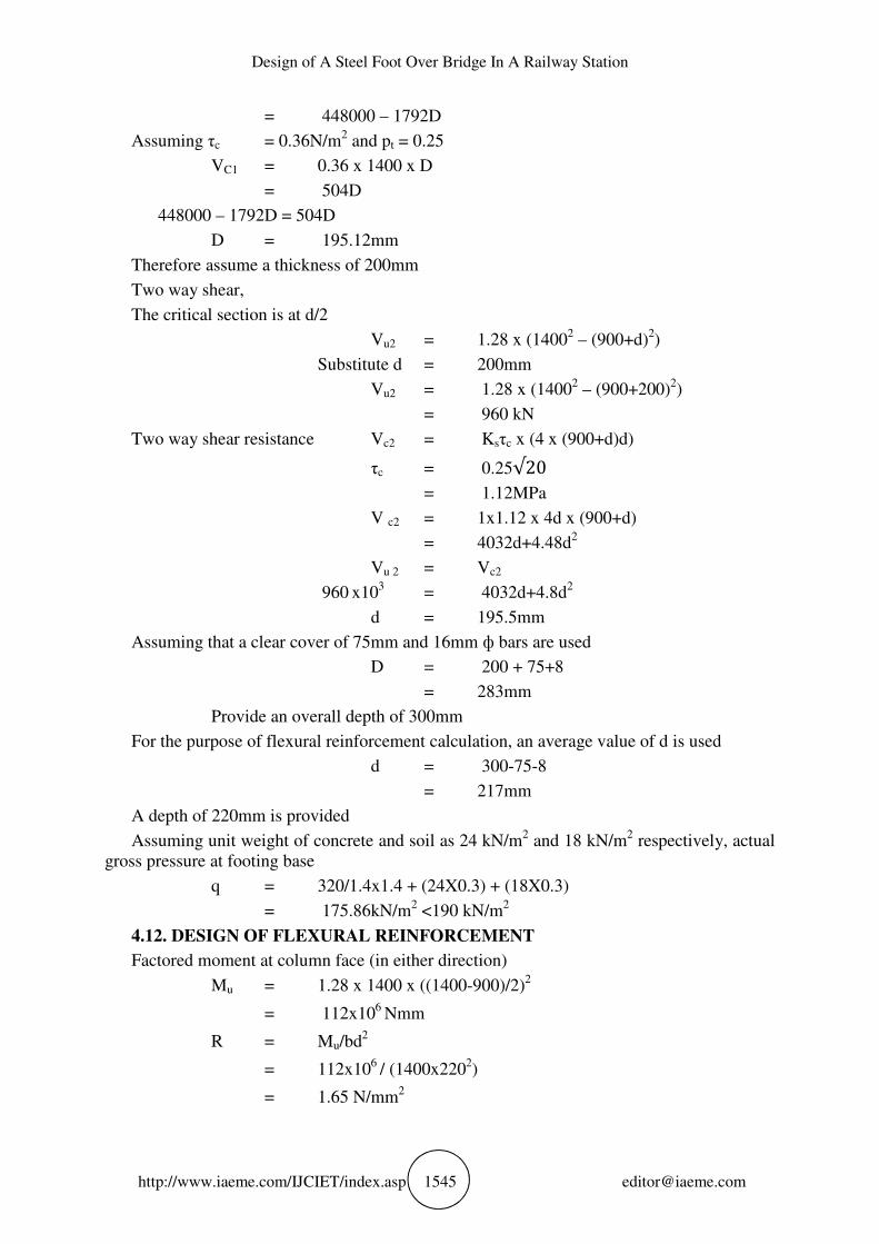
= 448000 – 1792D
Assuming τc = 0.36N/m2 and pt = 0.25
VC1 = 0.36 x 1400 x D
= 504D
448000 – 1792D = 504D
D = 195.12mm
Therefore assume a thickness of 200mm
Two way shear,
The critical section is at d/2
Vu2 = 1.28 x (14002 – (900+d)
2)
Substitute d = 200mm
Vu2 = 1.28 x (14002 – (900+200)
2)
= 960 kN
Two way shear resistance Vc2 = Ksτc x (4 x (900+d)d)
τc = 0.25√20
= 1.12MPa
V c2 = 1x1.12 x 4d x (900+d)
= 4032d+4.48d2
Vu 2 = Vc2
960 x10
3 = 4032d+4.8d
2
d = 195.5mm
Assuming that a clear cover of 75mm and 16mm ф bars are used
D = 200 + 75+8
= 283mm
Provide an overall depth of 300mm
For the purpose of flexural reinforcement calculation, an average value of d is used
d = 300-75-8
= 217mm
A depth of 220mm is provided
Assuming unit weight of concrete and soil as 24 kN/m2 and 18 kN/m
2 respectively, actual
gross pressure at footing base
q = 320/1.4x1.4 + (24X0.3) + (18X0.3)
= 175.86kN/m2 <190 kN/m
2
4.12. DESIGN OF FLEXURAL REINFORCEMENT
Factored moment at column face (in either direction)
Mu = 1.28 x 1400 x ((1400-900)/2)2
= 112x106
Nmm
R = Mu/bd2
= 112x106
/ (1400x2202)
= 1.65 N/mm2
S.Rajesh
http://www.iaeme.com/IJCIET/index.asp 1546 [email protected]
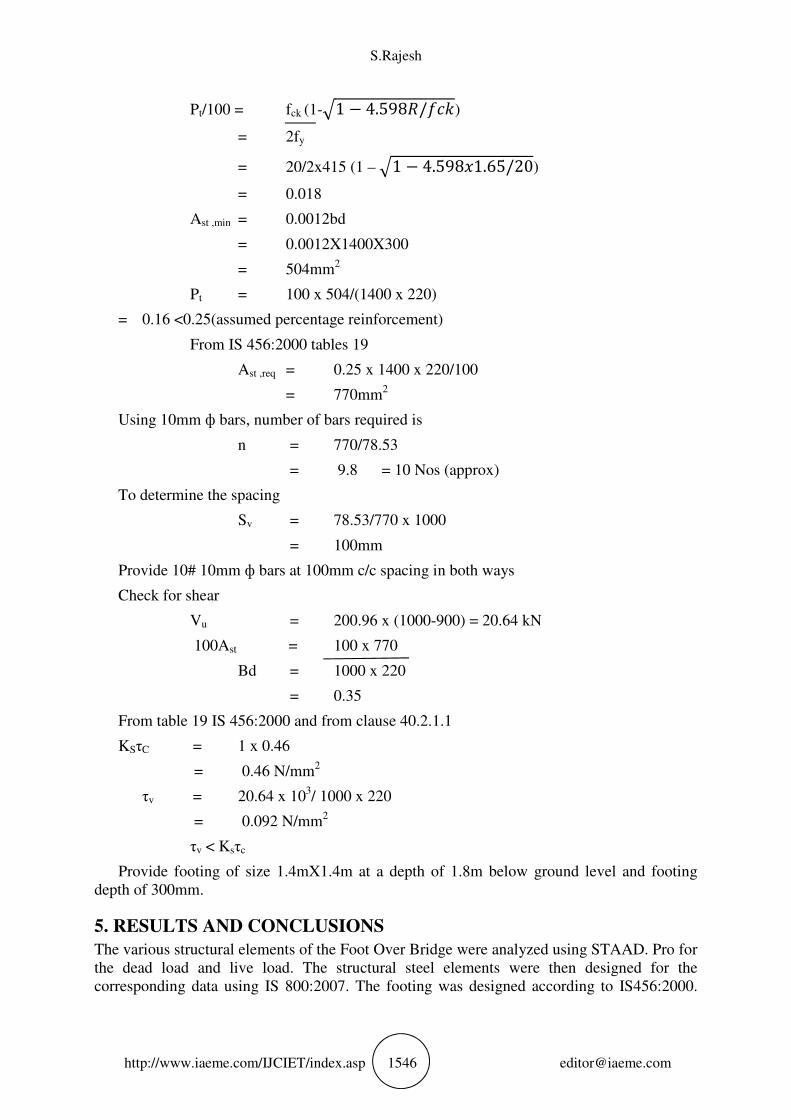
Pt/100 = fck (1-*1 − 4.598,/./0)
= 2fy
= 20/2x415 (1 – *1 − 4.598(1.65/20)
= 0.018
Ast ,min = 0.0012bd
= 0.0012X1400X300
= 504mm2
Pt = 100 x 504/(1400 x 220)
= 0.16 <0.25(assumed percentage reinforcement)
From IS 456:2000 tables 19
Ast ,req = 0.25 x 1400 x 220/100
= 770mm2
Using 10mm ф bars, number of bars required is
n = 770/78.53
= 9.8 = 10 Nos (approx)
To determine the spacing
Sv = 78.53/770 x 1000
= 100mm
Provide 10# 10mm ф bars at 100mm c/c spacing in both ways
Check for shear
Vu = 200.96 x (1000-900) = 20.64 kN
100Ast = 100 x 770
Bd = 1000 x 220
= 0.35
From table 19 IS 456:2000 and from clause 40.2.1.1
KSτC = 1 x 0.46
= 0.46 N/mm2
τv = 20.64 x 10³/ 1000 x 220
= 0.092 N/mm2
τv < Ksτc
Provide footing of size 1.4mX1.4m at a depth of 1.8m below ground level and footing
depth of 300mm.
5. RESULTS AND CONCLUSIONS
The various structural elements of the Foot Over Bridge were analyzed using STAAD. Pro for
the dead load and live load. The structural steel elements were then designed for the
corresponding data using IS 800:2007. The footing was designed according to IS456:2000.
Design of A Steel Foot Over Bridge In A Railway Station
http://www.iaeme.com/IJCIET/index.asp 1547 [email protected]
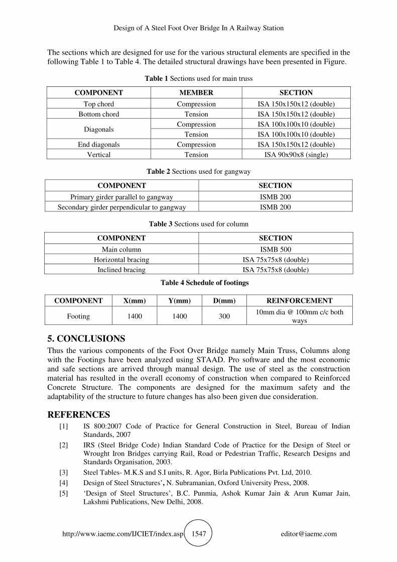
The sections which are designed for use for the various structural elements are specified in the
following Table 1 to Table 4. The detailed structural drawings have been presented in Figure.
Table 1 Sections used for main truss
COMPONENT MEMBER SECTION
Top chord Compression ISA 150x150x12 (double)
Bottom chord Tension ISA 150x150x12 (double)
Diagonals Compression ISA 100x100x10 (double)
Tension ISA 100x100x10 (double)
End diagonals Compression ISA 150x150x12 (double)
Vertical Tension ISA 90x90x8 (single)
Table 2 Sections used for gangway
COMPONENT SECTION
Primary girder parallel to gangway ISMB 200
Secondary girder perpendicular to gangway ISMB 200
Table 3 Sections used for column
COMPONENT SECTION
Main column ISMB 500
Horizontal bracing ISA 75x75x8 (double)
Inclined bracing ISA 75x75x8 (double)
Table 4 Schedule of footings
COMPONENT X(mm) Y(mm) D(mm) REINFORCEMENT
Footing 1400 1400 300 10mm dia @ 100mm c/c both
ways
5. CONCLUSIONS
Thus the various components of the Foot Over Bridge namely Main Truss, Columns along
with the Footings have been analyzed using STAAD. Pro software and the most economic
and safe sections are arrived through manual design. The use of steel as the construction
material has resulted in the overall economy of construction when compared to Reinforced
Concrete Structure. The components are designed for the maximum safety and the
adaptability of the structure to future changes has also been given due consideration.
REFERENCES
[1] IS 800:2007 Code of Practice for General Construction in Steel, Bureau of Indian
Standards, 2007
[2] IRS (Steel Bridge Code) Indian Standard Code of Practice for the Design of Steel or
Wrought Iron Bridges carrying Rail, Road or Pedestrian Traffic, Research Designs and
Standards Organisation, 2003.
[3] Steel Tables- M.K.S and S.I units, R. Agor, Birla Publications Pvt. Ltd, 2010.
[4] Design of Steel Structures’, N. Subramanian, Oxford University Press, 2008.
[5] ‘Design of Steel Structures’, B.C. Punmia, Ashok Kumar Jain & Arun Kumar Jain,
Lakshmi Publications, New Delhi, 2008.
S.Rajesh
http://www.iaeme.com/IJCIET/index.asp 1548 [email protected]
[6] Design of Steel Structures’, S.K. Duggal, Tata McGraw-Hill Publishing Company
Limited, New Delhi, 2009.
[7] Limit State Design of Reinforced Concrete, P.C. Varghese, Phi Learning Edition, New
Delhi, 2006.
[8] Reinforced Concrete Design, S. Unnikrishna Pillai, Menon Devadas, Tata McGraw-
Hill Publishing Company Limited, New Delhi, 2003.
[9] Kumar J., Sathish Kumar K., Dayakar P., Effect of microsilica on high strength concrete,
International Journal of Applied Engineering Research, v-9, i-22, pp-5427-5432, 2014.
[10] Iyappan L., Dayakar P., Identification of landslide prone zone for coonoor taluk using
spatial technology, International Journal of Applied Engineering Research, v-9, i-22, pp-
5724-5732, 2014.
[11] Swaminathan N., Dayakar P., Resource optimization in construction project, International
Journal of Applied Engineering Research, v-9, i-22, pp-5546-5551, 2014.
[12] Swaminathan N., Sachithanandam P., Risk assessment in construction project,
International Journal of Applied Engineering Research, v-9, i-22, pp-5552-5557, 2014.
[13] Srividya T., Kaviya B., Effect on mesh reinforcement on the permeablity and strength of
pervious concrete, International Journal of Applied Engineering Research, v-9, i-22, pp-
5530-5532, 2014.
[14] Sandhiya K., Kaviya B., Safe bus stop location in Trichy city by using gis, International
Journal of Applied Engineering Research, v-9, i-22, pp-5686-5691, 2014.
[15] Ajona M., Kaviya B., An environmental friendly self-healing microbial concrete,
International Journal of Applied Engineering Research, v-9, i-22, pp-5457-5462, 2014.
[16] Kumar J., Sachithanandam P., Experimental investigation on concrete with partial
replacement of scrap rubber to granite stones as coarse aggregate, International Journal of
Applied Engineering Research, v-9, i-22, pp-5733-5740, 2014.
[17] Sachithanandam P., Meikandaan T.P., Srividya T., Steel framed multi storey residential
building analysis and design, International Journal of Applied Engineering Research, v-9,
i-22, pp-5527-5529, 2014.
[18] Srividya T., Saritha B., Strengthening on RC beam elements with GFRP under flexure,
International Journal of Applied Engineering Research, v-9, i-22, pp-5443-5446, 2014.
[19] Saraswathy R., Saritha B., Planning of integrated Satellite Township at Thirumazhisai,
International Journal of Applied Engineering Research, v-9, i-22, pp-5558-5560, 2014.
[20] Saritha B., Rajasekhar K., Removal of malachite green and methylene blue using low cost
adsorbents from aqueous medium-a review, Middle - East Journal of Scientific Research,
v-17, i-12, pp-1779-1784, 2013.
[21] Ciro Caliendo Simplified Models for Estimating Stresses and Strains in Pavements on
Concrete and Steel Bridges. International Journal of Civil Engineering and Technology,
8(7), 2017, pp. 1273-1282
[22] Zaman Abbas Kazmi, Ashhad Imam and Vikas Srivastava, Analysis and Design of Box
Type Minor Railway Bridge, International Journal of Civil Engineering and Technology,
8(7), 2017, pp. 295–306.


![Sengiergi Serafeim Tikozoglou [Main]](https://static.fdocument.org/doc/165x107/5477673a5806b5e7738b456f/sengiergi-serafeim-tikozoglou-main.jpg)