Electric Potential Energy and Electric Potential Chapter 16.
7th BETA CAE International Conference
DESIGN AND DEVELOPMENT OF A PROTOTYPE ELECTRIC VEHICLE’S CHASSIS Georgios Koumartzakis, Polychronis Spanoudakis*, Nikolaos C. Tsourveloudis School of Production Engineering and Management, Technical University of Crete, Greece KEYWORDS – Chassis evaluation, linear static analysis, modal analysis, ANSA, EPILYSIS, MΕΤΑ ABSTRACT – The automotive chassis is one of the most important structures of any self-propelled con-struction because of its multifaceted role on vehicle dynamic behavior. This paper presents the design and the development of a chassis, for the one-seated prototype electric vehicle “Louis”, developed by Technical University of Crete Eco Racing (TUCER) team. The main target is to evaluate chassis deformation, based on static and modal analysis, in order to re-duce weight and at the same time achieve adequate vehicle operation in a demanding low energy consumption race. The design is carried out based on specific standards and limita-tions set by the competition regulations. The modeling process is conducted using the ANSA pre-processor. The specifications of chassis materials linked to mechanical and physical properties are defined and set. Static loads are calculated and placed on the frame, in order to run the finite element analysis using the EPILYSIS solver and results are evaluated using META. A modal analysis is also set up and run, to determine the natural frequencies and the mode shapes of the chassis, so to partly understand the dynamic behavior of this structure. All above mentioned analyses are conducted for the 2014, 2015 and 2016 vehicles chassis. The results obtained provide a valuable insight on the evaluation procedure, final weight and factor of safety calculated. A significant reduction of weight is achieved and presented through the comparison of the three chassis versions. TECHNICAL PAPER - 1. INTRODUCTION The automotive industry today is confronted with perhaps some of the most significant tech-nical challenges in its history. In most regions of the world, regulations and legislation are being enacted to enforce higher fuel economy and lower tailpipe emissions. In all cases the trend is upward and in some regions the impending regulations are forcing a substantially greater emphasis on improving fuel economy. These challenges, along with quickly changing customer preferences and the ever-increasing market demand for better vehicle performance and reliability, require automotive companies to rethink past approaches and to find better ways to design better vehicles at lower costs in shorter time. Simulation provides a strong opportunity and means to bring about some of the necessary cost efficiencies, while at the same time providing the platform to drive innovative product development. Moreover, simulation methods continue to advance in sophistication as well as the level of fidelity and accuracy they can provide. This ongoing evolution is partly fueled by the relentless geometric growth in the capacity and availability of high performance computing. In this paper, the use of such simulation methods is used to design a new chassis for the one-seated prototype electric vehicle “Louis”, of TUC Eco Racing (TUCER) team. The weight reduction, the effective design and the solidity of the structure are the key objectives in order to result to the best possible product design. The main target is a new car with better energy consumption and additionally: construction simplicity, ease of processing and placement of materials. The tools provided by Beta CAE Systems suite ensure that the optimization is done efficiently, in a short time and without the need for experiments with physical models.
7th BETA CAE International Conference
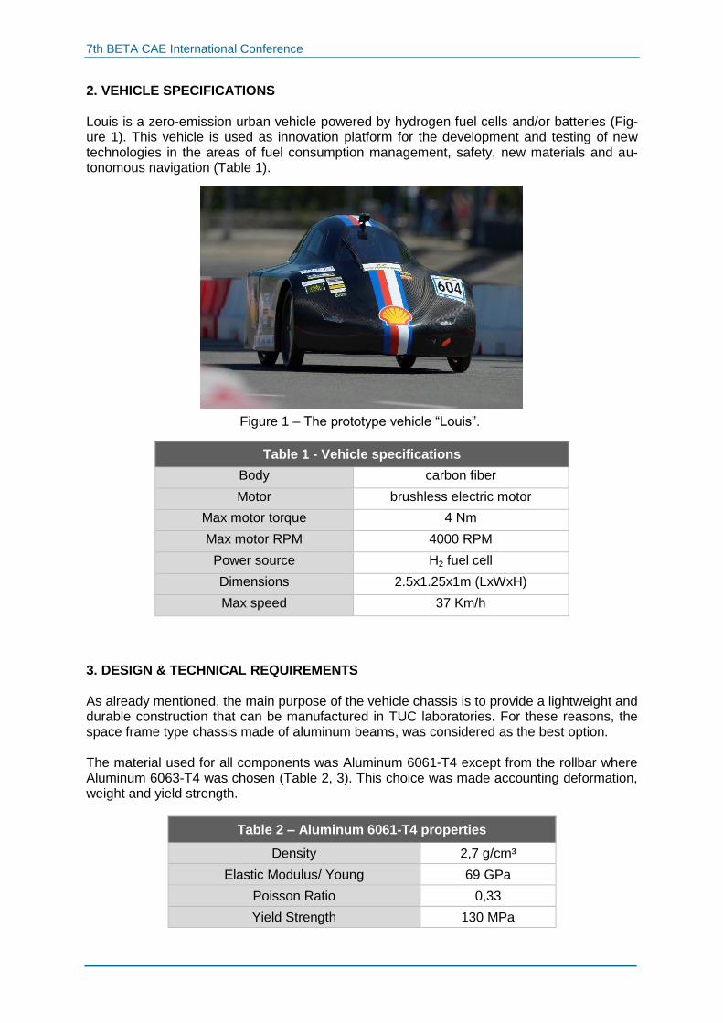
2. VEHICLE SPECIFICATIONS Louis is a zero-emission urban vehicle powered by hydrogen fuel cells and/or batteries (Fig-ure 1). This vehicle is used as innovation platform for the development and testing of new technologies in the areas of fuel consumption management, safety, new materials and au-tonomous navigation (Table 1).
Table 1 - Vehicle specifications
Body carbon fiber
Motor brushless electric motor
Max motor torque 4 Nm
Max motor RPM 4000 RPM
Power source H2 fuel cell
Dimensions 2.5x1.25x1m (LxWxH)
Max speed 37 Km/h
3. DESIGN & TECHNICAL REQUIREMENTS As already mentioned, the main purpose of the vehicle chassis is to provide a lightweight and durable construction that can be manufactured in TUC laboratories. For these reasons, the space frame type chassis made of aluminum beams, was considered as the best option. The material used for all components was Aluminum 6061-T4 except from the rollbar where Aluminum 6063-T4 was chosen (Table 2, 3). This choice was made accounting deformation, weight and yield strength.
Table 2 – Aluminum 6061-T4 properties
Density 2,7 g/cm³
Elastic Modulus/ Young 69 GPa
Poisson Ratio 0,33
Yield Strength 130 MPa
Figure 1 – The prototype vehicle “Louis”.
7th BETA CAE International Conference
Table 3 – Aluminum 6063-T4 properties
Density 2,69 g/cm³
Elastic Modulus/ Young 69 GPa
Poisson Ratio 0,33
Yield Strength 80 MPa
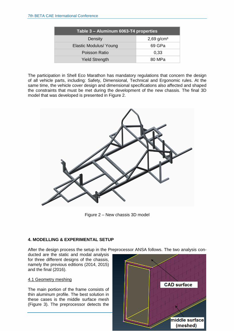
The participation in Shell Eco Marathon has mandatory regulations that concern the design of all vehicle parts, including: Safety, Dimensional, Technical and Ergonomic rules. At the same time, the vehicle cover design and dimensional specifications also affected and shaped the constraints that must be met during the development of the new chassis. The final 3D model that was developed is presented in Figure 2.
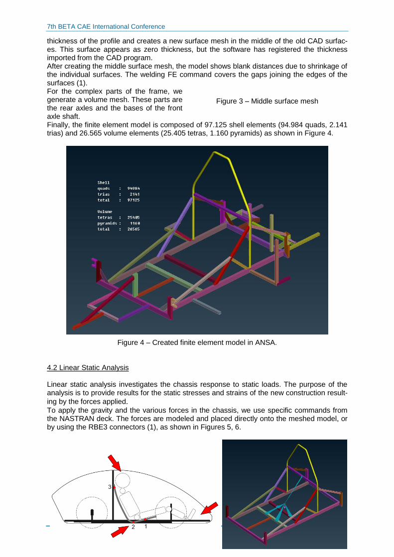
Figure 2 – New chassis 3D model 4. MODELLING & EXPERIMENTAL SETUP After the design process the setup in the Preprocessor ANSA follows. The two analysis con-ducted are the static and modal analysis for three different designs of the chassis, namely the previous editions (2014, 2015) and the final (2016). 4.1 Geometry meshing The main portion of the frame consists of thin aluminum profile. The best solution in these cases is the middle surface mesh (Figure 3). The preprocessor detects the
7th BETA CAE International Conference
Figure 3 – Middle surface mesh
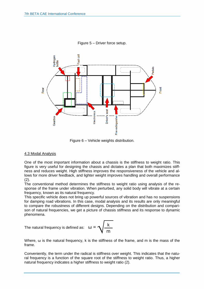
thickness of the profile and creates a new surface mesh in the middle of the old CAD surfac-es. This surface appears as zero thickness, but the software has registered the thickness imported from the CAD program. After creating the middle surface mesh, the model shows blank distances due to shrinkage of the individual surfaces. The welding FE command covers the gaps joining the edges of the surfaces (1). For the complex parts of the frame, we generate a volume mesh. These parts are the rear axles and the bases of the front axle shaft. Finally, the finite element model is composed of 97.125 shell elements (94.984 quads, 2.141 trias) and 26.565 volume elements (25.405 tetras, 1.160 pyramids) as shown in Figure 4.
Figure 4 – Created finite element model in ANSA. 4.2 Linear Static Analysis Linear static analysis investigates the chassis response to static loads. The purpose of the analysis is to provide results for the static stresses and strains of the new construction result-
ing by the forces applied. To apply the gravity and the various forces in the chassis, we use specific commands from the NASTRAN deck. The forces are modeled and placed directly onto the meshed model, or by using the RBE3 connectors (1), as shown in Figures 5, 6.
7th BETA CAE International Conference
Figure 5 – Driver force setup.
Figure 6 – Vehicle weights distribution.
4.3 Modal Analysis One of the most important information about a chassis is the stiffness to weight ratio. This figure is very useful for designing the chassis and dictates a plan that both maximizes stiff-ness and reduces weight. High stiffness improves the responsiveness of the vehicle and al-lows for more driver feedback, and lighter weight improves handling and overall performance (2). The conventional method determines the stiffness to weight ratio using analysis of the re-sponse of the frame under vibration. When perturbed, any solid body will vibrate at a certain frequency, known as its natural frequency. This specific vehicle does not bring up powerful sources of vibration and has no suspensions for damping road vibrations. In this case, modal analysis and its results are only meaningful to compare the robustness of different designs. Depending on the distribution and compari-son of natural frequencies, we get a picture of chassis stiffness and its response to dynamic phenomena. The natural frequency is defined as: Where, ω is the natural frequency, k is the stiffness of the frame, and m is the mass of the frame. Conveniently, the term under the radical is stiffness over weight. This indicates that the natu-ral frequency is a function of the square root of the stiffness to weight ratio. Thus, a higher natural frequency indicates a higher stiffness to weight ratio (2).
7th BETA CAE International Conference
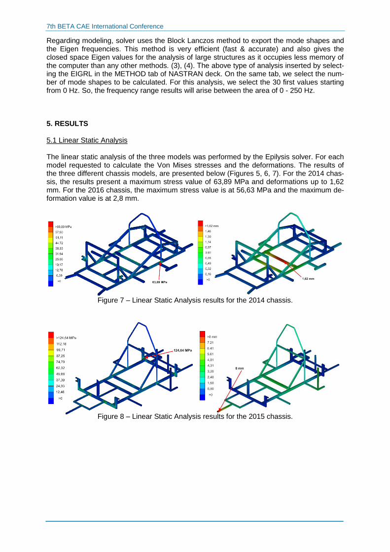
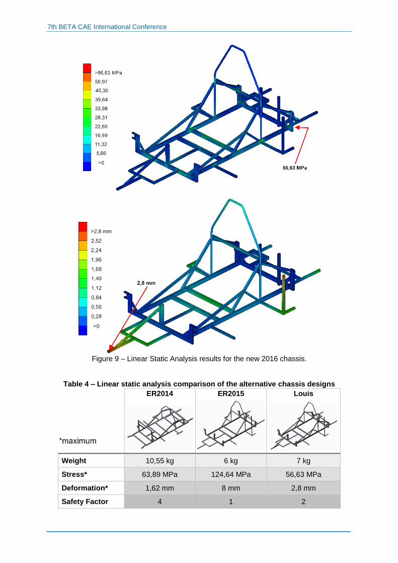
Regarding modeling, solver uses the Block Lanczos method to export the mode shapes and the Eigen frequencies. This method is very efficient (fast & accurate) and also gives the closed space Eigen values for the analysis of large structures as it occupies less memory of the computer than any other methods. (3), (4). Τhe above type of analysis inserted by select-ing the EIGRL in the METHOD tab of NASTRAN deck. On the same tab, we select the num-ber of mode shapes to be calculated. For this analysis, we select the 30 first values starting from 0 Hz. So, the frequency range results will arise between the area of 0 - 250 Hz. 5. RESULTS 5.1 Linear Static Analysis The linear static analysis of the three models was performed by the Epilysis solver. For each model requested to calculate the Von Mises stresses and the deformations. The results of the three different chassis models, are presented below (Figures 5, 6, 7). For the 2014 chas-sis, the results present a maximum stress value of 63,89 MPa and deformations up to 1,62 mm. For the 2016 chassis, the maximum stress value is at 56,63 MPa and the maximum de-formation value is at 2,8 mm.
Figure 7 – Linear Static Analysis results for the 2014 chassis.
Figure 8 – Linear Static Analysis results for the 2015 chassis.
7th BETA CAE International Conference
Figure 9 – Linear Static Analysis results for the new 2016 chassis.
Table 4 – Linear static analysis comparison of the alternative chassis designs
ER2014
ER2015
Louis
Weight 10,55 kg 6 kg 7 kg
Stress* 63,89 MPa 124,64 MPa 56,63 MPa
Deformation* 1,62 mm 8 mm 2,8 mm
Safety Factor 4 1 2
7th BETA CAE International Conference
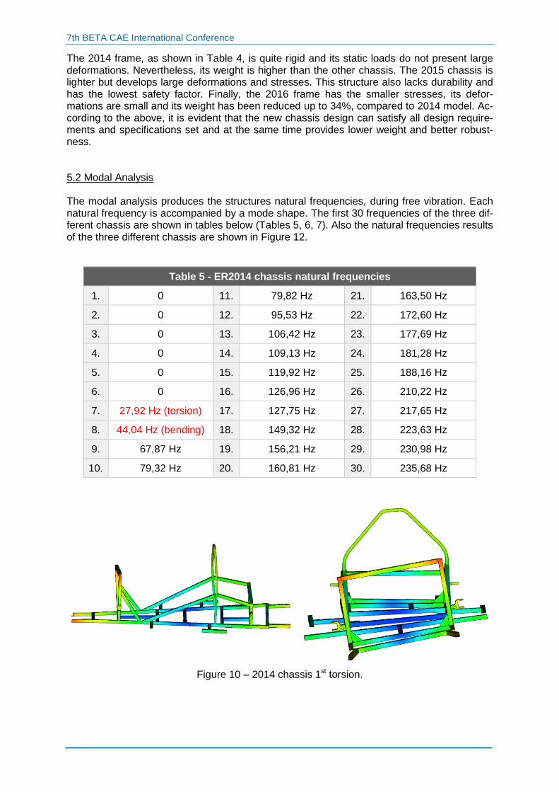
The 2014 frame, as shown in Table 4, is quite rigid and its static loads do not present large deformations. Nevertheless, its weight is higher than the other chassis. The 2015 chassis is lighter but develops large deformations and stresses. This structure also lacks durability and has the lowest safety factor. Finally, the 2016 frame has the smaller stresses, its defor-mations are small and its weight has been reduced up to 34%, compared to 2014 model. Ac-cording to the above, it is evident that the new chassis design can satisfy all design require-ments and specifications set and at the same time provides lower weight and better robust-ness. 5.2 Modal Analysis The modal analysis produces the structures natural frequencies, during free vibration. Each natural frequency is accompanied by a mode shape. The first 30 frequencies of the three dif-ferent chassis are shown in tables below (Tables 5, 6, 7). Also the natural frequencies results of the three different chassis are shown in Figure 12.
Table 5 - ER2014 chassis natural frequencies
1. 0 11. 79,82 Hz 21. 163,50 Hz
2. 0 12. 95,53 Hz 22. 172,60 Hz
3. 0 13. 106,42 Hz 23. 177,69 Hz
4. 0 14. 109,13 Hz 24. 181,28 Hz
5. 0 15. 119,92 Hz 25. 188,16 Hz
6. 0 16. 126,96 Hz 26. 210,22 Hz
7. 27,92 Hz (torsion) 17. 127,75 Hz 27. 217,65 Hz
8. 44,04 Hz (bending) 18. 149,32 Hz 28. 223,63 Hz
9. 67,87 Hz 19. 156,21 Hz 29. 230,98 Hz
10. 79,32 Hz 20. 160,81 Hz 30. 235,68 Hz
Figure 10 – 2014 chassis 1st torsion.
7th BETA CAE International Conference
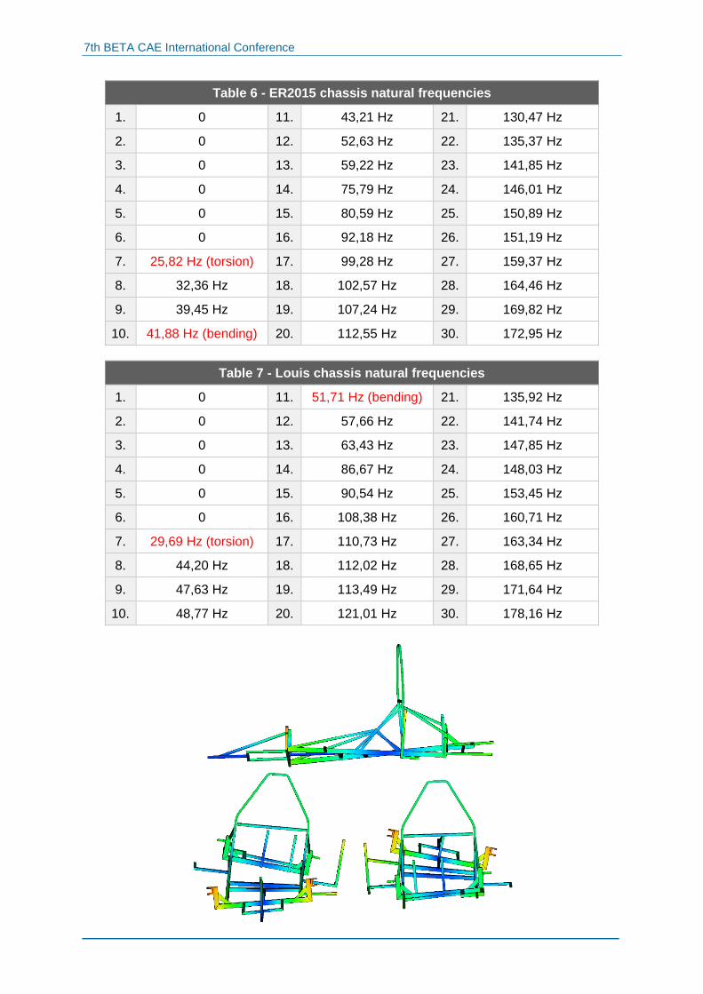
Table 6 - ER2015 chassis natural frequencies
1. 0 11. 43,21 Hz 21. 130,47 Hz
2. 0 12. 52,63 Hz 22. 135,37 Hz
3. 0 13. 59,22 Hz 23. 141,85 Hz
4. 0 14. 75,79 Hz 24. 146,01 Hz
5. 0 15. 80,59 Hz 25. 150,89 Hz
6. 0 16. 92,18 Hz 26. 151,19 Hz
7. 25,82 Hz (torsion) 17. 99,28 Hz 27. 159,37 Hz
8. 32,36 Hz 18. 102,57 Hz 28. 164,46 Hz
9. 39,45 Hz 19. 107,24 Hz 29. 169,82 Hz
10. 41,88 Hz (bending) 20. 112,55 Hz 30. 172,95 Hz
Table 7 - Louis chassis natural frequencies
1. 0 11. 51,71 Hz (bending) 21. 135,92 Hz
2. 0 12. 57,66 Hz 22. 141,74 Hz
3. 0 13. 63,43 Hz 23. 147,85 Hz
4. 0 14. 86,67 Hz 24. 148,03 Hz
5. 0 15. 90,54 Hz 25. 153,45 Hz
6. 0 16. 108,38 Hz 26. 160,71 Hz
7. 29,69 Hz (torsion) 17. 110,73 Hz 27. 163,34 Hz
8. 44,20 Hz 18. 112,02 Hz 28. 168,65 Hz
9. 47,63 Hz 19. 113,49 Hz 29. 171,64 Hz
10. 48,77 Hz 20. 121,01 Hz 30. 178,16 Hz
7th BETA CAE International Conference
Figure 11 – 2016 chassis 1st torsion.
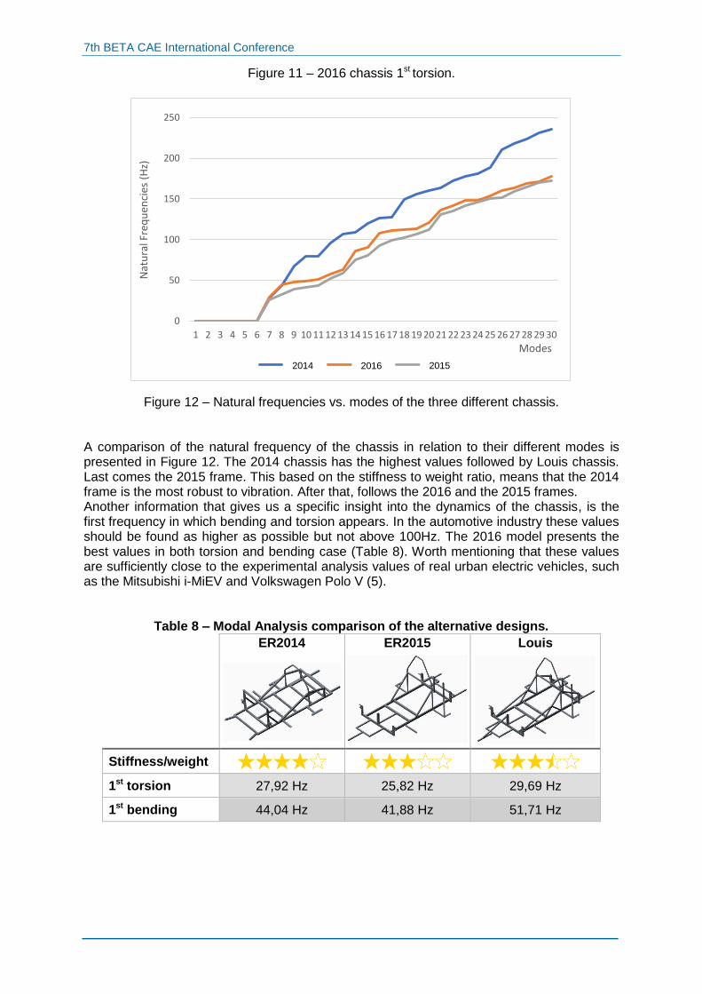
Figure 12 – Natural frequencies vs. modes of the three different chassis. A comparison of the natural frequency of the chassis in relation to their different modes is presented in Figure 12. The 2014 chassis has the highest values followed by Louis chassis. Last comes the 2015 frame. This based on the stiffness to weight ratio, means that the 2014 frame is the most robust to vibration. After that, follows the 2016 and the 2015 frames. Another information that gives us a specific insight into the dynamics of the chassis, is the first frequency in which bending and torsion appears. In the automotive industry these values should be found as higher as possible but not above 100Hz. The 2016 model presents the best values in both torsion and bending case (Table 8). Worth mentioning that these values are sufficiently close to the experimental analysis values of real urban electric vehicles, such as the Mitsubishi i-MiEV and Volkswagen Polo V (5).
Table 8 – Modal Analysis comparison of the alternative designs.
ER2014
ER2015
Louis
Stiffness/weight
1st torsion 27,92 Hz 25,82 Hz 29,69 Hz
1st bending 44,04 Hz 41,88 Hz 51,71 Hz
0
50
100
150
200
250
1 2 3 4 5 6 7 8 9 10 11 12 13 14 15 16 17 18 19 20 21 22 23 24 25 26 27 28 29 30
Nat
ura
l Fre
qu
enci
es (
Hz)
Modes
Series1 Series2 Series32014 2015 2016
7th BETA CAE International Conference
6. CONCLUSIONS This paper presents the design and development process of a chassis, for the one-seated prototype electric vehicle “Louis”, developed by Technical University of Crete Eco Racing team. The main target is to evaluate chassis response, based on static and modal analysis, in order to reduce weight and at the same time achieve adequate vehicle operation in a de-manding low energy consumption race. The design is carried out based on specific stand-ards and limitations set by the competition regulations. All analysis are carried out for three different chassis models, respectively 2014, 2015 and 2016 (Louis vehicle), modeled in AN-SA, solved with the Epilysis solver and evaluated using META post-processor. The static analysis for each model is set to calculate the Von Mises stresses and defor-mations. The results presented, point out that the 2016 frame has stresses and deformations lower than the material yield strength and its weight (7Kg) has been reduced up to 34%, compared to 2014 model (10.55Kg). The 2015 chassis is lighter (6Kg) but large deformations and stresses occur resulting to the lowest safety factor. The modal analysis produces structure natural frequencies, during free vibration. Each natu-ral frequency is accompanied by a mode shape. In this study the first 30 frequencies of the three different chassis are considered. As found, the 2014 chassis has the highest values followed by 2016 (Louis) model, while 2015 model has the lower observed. Based on the stiffness to weight ratio, the 2014 model is the most robust to vibration, then follows the 2016 and the 2015 model. Another information that gives us a specific insight into the dynamics of the chassis, is the first frequency in which bending and torsion appears. In the automotive industry these values should be found as higher as possible but not above 100Hz. The 2016 model presents the best values in both torsion and bending case. Worth mentioning that these values are suffi-ciently close to the experimental analysis values of real urban electric vehicles, such as the Mitsubishi i-MiEV and Volkswagen Polo V. According to the above, it is evident that the new chassis (2016) can satisfy all design re-quirements and specifications set and at the same time provides lower weight, better stiff-ness to weight ratio and adequate response in bending and torsion frequencies. REFERENCES (1) ANSA version 17.0.0 User’s Guide, BETA CAE Systems, July 2015 (2) Marzuki M.A.B., Halim M.H.A., Mohamed A.R.N., Determination of Natural Frequen-
cies through Modal and Harmonic Analysis of Space Frame Race Car Chassis Based
on ANSYS, American Journal of Engineering and Applied Sciences, 2015.
(3) Heißing B. & Ersoy M., Chassis Handbook Fundamentals, Driving Dynamics, Com-
ponents, Mechatronics, Perspectives, Berlin 2011.
(4) MSC Software, MSC Nastran 2012 Quick Reference Guide, MSC Software publish-
ing.
(5) Eckstein L., Wohlecker R., Göbbels R., Determination of the Functional Performance
of a Series Electric Vehicle. Beijing 2011.