Design Aids
28
Design Aid J.1-1 Areas of Reinforcing Bars Design Aid J.1-2 Approximate Bending Moments and Shear Forces for Continuous Beams and One- way Slabs Design Aid J.1-3 Variation of φ with Net Tensile Strain in Extreme Tension Steel ε t and c / d t – Grade 60 Reinforcement and Prestressing Steel Design Aid J.1-4 Simplified Calculation of A s Assuming Tension-Controlled Section and Grade 60 Reinforcement Design Aid J.1-5 Minimum Number of Reinforcing Bars Required in a Single Layer Design Aid J.1-6 Maximum Number of Reinforcing Bars Permitted in a Single Layer Design Aid J.1-7 Minimum Thickness h for Beams and One-Way Slabs Unless Deflections are Calculated Design Aid J.1-8 Reinforcement Ratio ρ t for Tension-Controlled Sections Assuming Grade 60 Reinforcement Design Aid J.1-9 Simplified Calculation of b w Assuming Grade 60 Reinforcement and ρ = 0.5 ρ max Design Aid J.1-10 T-beam Construction Design Aid J.1-11 Values of φV s = V u - φV c (kips) as a Function of the Spacing, s Design Aid J.1-12 Minimum Shear Reinforcement A v, min / s Design Aid J.1-13 Torsional Section Properties Design Aid J.1-14 Moment of Inertia of Cracked Section Transformed to Concrete, I cr Design Aid J.1-15 Approximate Equation to Determine Immediate Deflection, Δ i , for Members Subjected to Uniformly Distributed Loads Design Aids J.2 Two-Way Slabs – Direct Design method, includes the following: • Conditions for Analysis by the Direct Design Method • Definitions of Column Strip and Middle Strip • Definition of Clear Span, • Design Moment Coefficients used with the Direct Design Method • Effective Beam and Slab Sections for Computation of Stiffness Ratio, α f • Computation of Torsional Stiffness Factor, β t , for T- and L-Sections • Moment Distribution Constants for Slab-Beam Members without Drop Panels • Stiffness and Carry-Over Factors for Columns
-
Upload
resurrection786 -
Category
Documents
-
view
226 -
download
3
Transcript of Design Aids
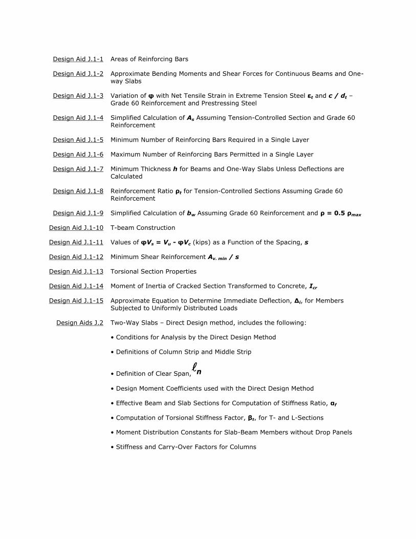
Design Aid J.1-1 Areas of Reinforcing Bars
Design Aid J.1-2 Approximate Bending Moments and Shear Forces for Continuous Beams and One-way Slabs
Design Aid J.1-3 Variation of φ with Net Tensile Strain in Extreme Tension Steel εt and c / dt –
Grade 60 Reinforcement and Prestressing Steel
Design Aid J.1-4 Simplified Calculation of As Assuming Tension-Controlled Section and Grade 60 Reinforcement
Design Aid J.1-5 Minimum Number of Reinforcing Bars Required in a Single Layer
Design Aid J.1-6 Maximum Number of Reinforcing Bars Permitted in a Single Layer
Design Aid J.1-7 Minimum Thickness h for Beams and One-Way Slabs Unless Deflections are
Calculated
Design Aid J.1-8 Reinforcement Ratio ρt for Tension-Controlled Sections Assuming Grade 60 Reinforcement
Design Aid J.1-9 Simplified Calculation of bw Assuming Grade 60 Reinforcement and ρ = 0.5 ρmax
Design Aid J.1-10 T-beam Construction
Design Aid J.1-11 Values of φVs = Vu - φVc (kips) as a Function of the Spacing, s
Design Aid J.1-12 Minimum Shear Reinforcement Av, min / s
Design Aid J.1-13 Torsional Section Properties
Design Aid J.1-14 Moment of Inertia of Cracked Section Transformed to Concrete, Icr
Design Aid J.1-15 Approximate Equation to Determine Immediate Deflection, Δi, for Members Subjected to Uniformly Distributed Loads
Design Aids J.2 Two-Way Slabs – Direct Design method, includes the following:
• Conditions for Analysis by the Direct Design Method
• Definitions of Column Strip and Middle Strip
• Definition of Clear Span,
• Design Moment Coefficients used with the Direct Design Method
• Effective Beam and Slab Sections for Computation of Stiffness Ratio, αf
• Computation of Torsional Stiffness Factor, βt, for T- and L-Sections
• Moment Distribution Constants for Slab-Beam Members without Drop Panels
• Stiffness and Carry-Over Factors for Columns
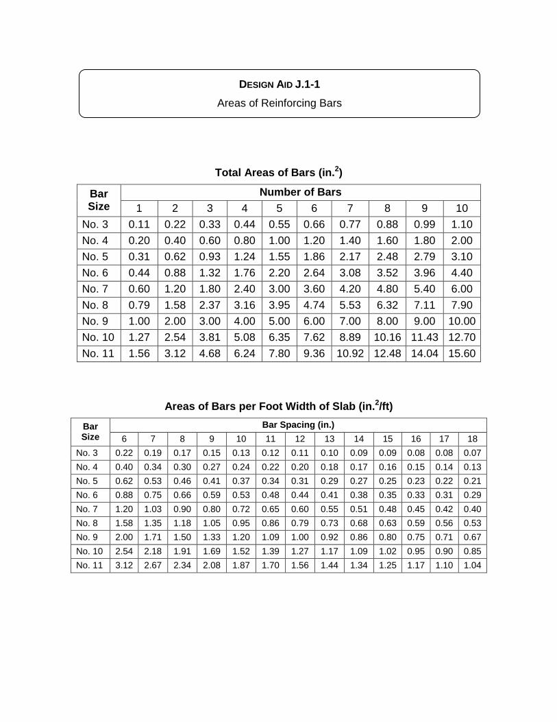
DESIGN AID J.1-1 Areas of Reinforcing Bars
Total Areas of Bars (in.2)
Bar Size
Number of Bars 1 2 3 4 5 6 7 8 9 10
No. 3 0.11 0.22 0.33 0.44 0.55 0.66 0.77 0.88 0.99 1.10 No. 4 0.20 0.40 0.60 0.80 1.00 1.20 1.40 1.60 1.80 2.00 No. 5 0.31 0.62 0.93 1.24 1.55 1.86 2.17 2.48 2.79 3.10 No. 6 0.44 0.88 1.32 1.76 2.20 2.64 3.08 3.52 3.96 4.40 No. 7 0.60 1.20 1.80 2.40 3.00 3.60 4.20 4.80 5.40 6.00 No. 8 0.79 1.58 2.37 3.16 3.95 4.74 5.53 6.32 7.11 7.90 No. 9 1.00 2.00 3.00 4.00 5.00 6.00 7.00 8.00 9.00 10.00 No. 10 1.27 2.54 3.81 5.08 6.35 7.62 8.89 10.16 11.43 12.70 No. 11 1.56 3.12 4.68 6.24 7.80 9.36 10.92 12.48 14.04 15.60
Areas of Bars per Foot Width of Slab (in.2/ft)
Bar Size
Bar Spacing (in.) 6 7 8 9 10 11 12 13 14 15 16 17 18
No. 3 0.22 0.19 0.17 0.15 0.13 0.12 0.11 0.10 0.09 0.09 0.08 0.08 0.07 No. 4 0.40 0.34 0.30 0.27 0.24 0.22 0.20 0.18 0.17 0.16 0.15 0.14 0.13 No. 5 0.62 0.53 0.46 0.41 0.37 0.34 0.31 0.29 0.27 0.25 0.23 0.22 0.21 No. 6 0.88 0.75 0.66 0.59 0.53 0.48 0.44 0.41 0.38 0.35 0.33 0.31 0.29 No. 7 1.20 1.03 0.90 0.80 0.72 0.65 0.60 0.55 0.51 0.48 0.45 0.42 0.40 No. 8 1.58 1.35 1.18 1.05 0.95 0.86 0.79 0.73 0.68 0.63 0.59 0.56 0.53 No. 9 2.00 1.71 1.50 1.33 1.20 1.09 1.00 0.92 0.86 0.80 0.75 0.71 0.67 No. 10 2.54 2.18 1.91 1.69 1.52 1.39 1.27 1.17 1.09 1.02 0.95 0.90 0.85 No. 11 3.12 2.67 2.34 2.08 1.87 1.70 1.56 1.44 1.34 1.25 1.17 1.10 1.04
mrs
Typewritten Text
mrs
Typewritten Text
mrs
Typewritten Text
mrs
Typewritten Text
mrs
Typewritten Text
pfs
314 Design Aid
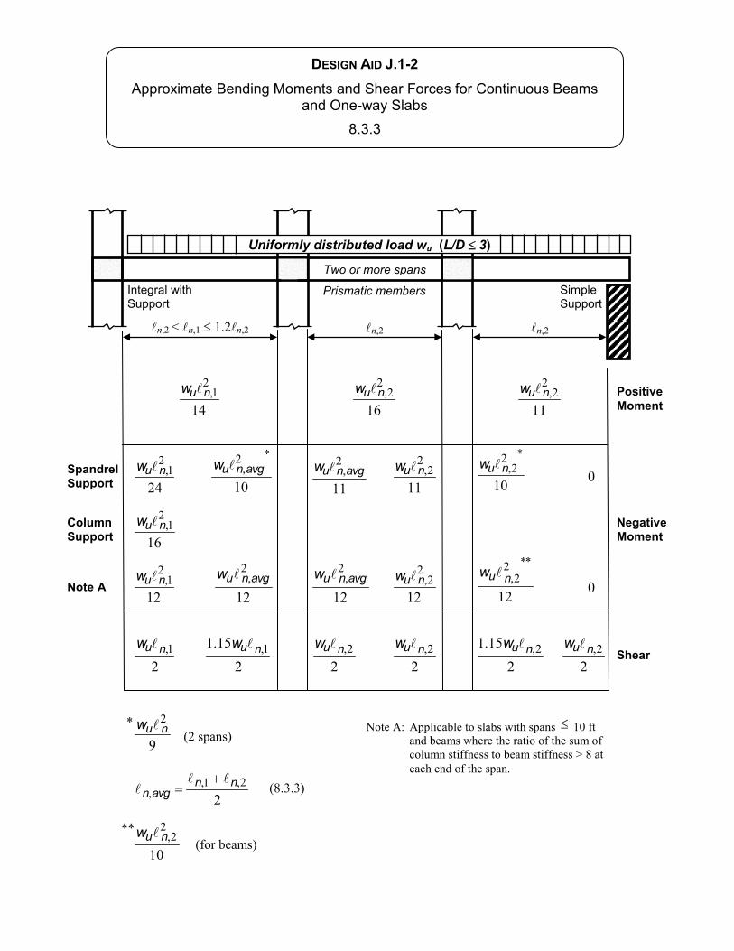
PositiveMoment
NegativeMoment
Shear
n n n n
Prismatic members
n
nuw nuw nuw
nuw avgnuw avgnuw nuw nuwSpandrelSupport
ColumnSupport
nuw
nuw nuwnuw nuwnuw nuw
nuw
nnavgn
Note A nuw avgnuw avgnuw nuw nuw
Two or more spans
Uniformly distributed load wu (L/D 3)
nuw
DESIGN AID J.1-2
pfs
314 Design Aid
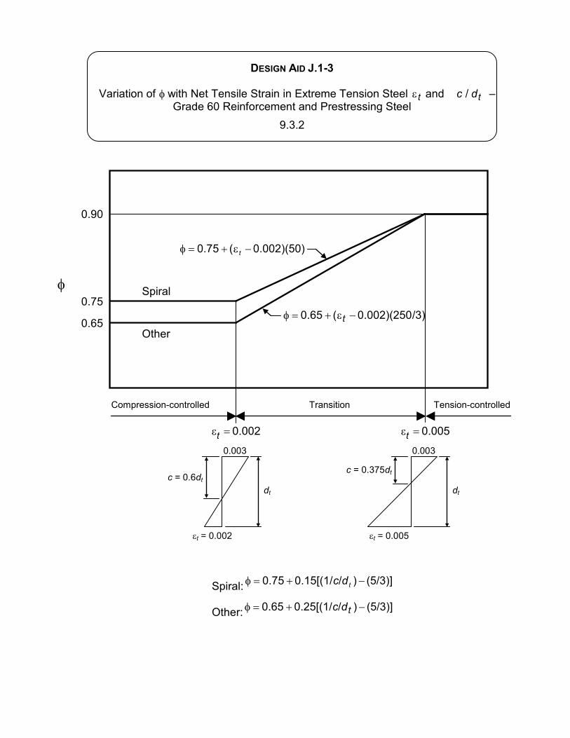
DESIGN AID J.1-3
pfs
314 Design Aid
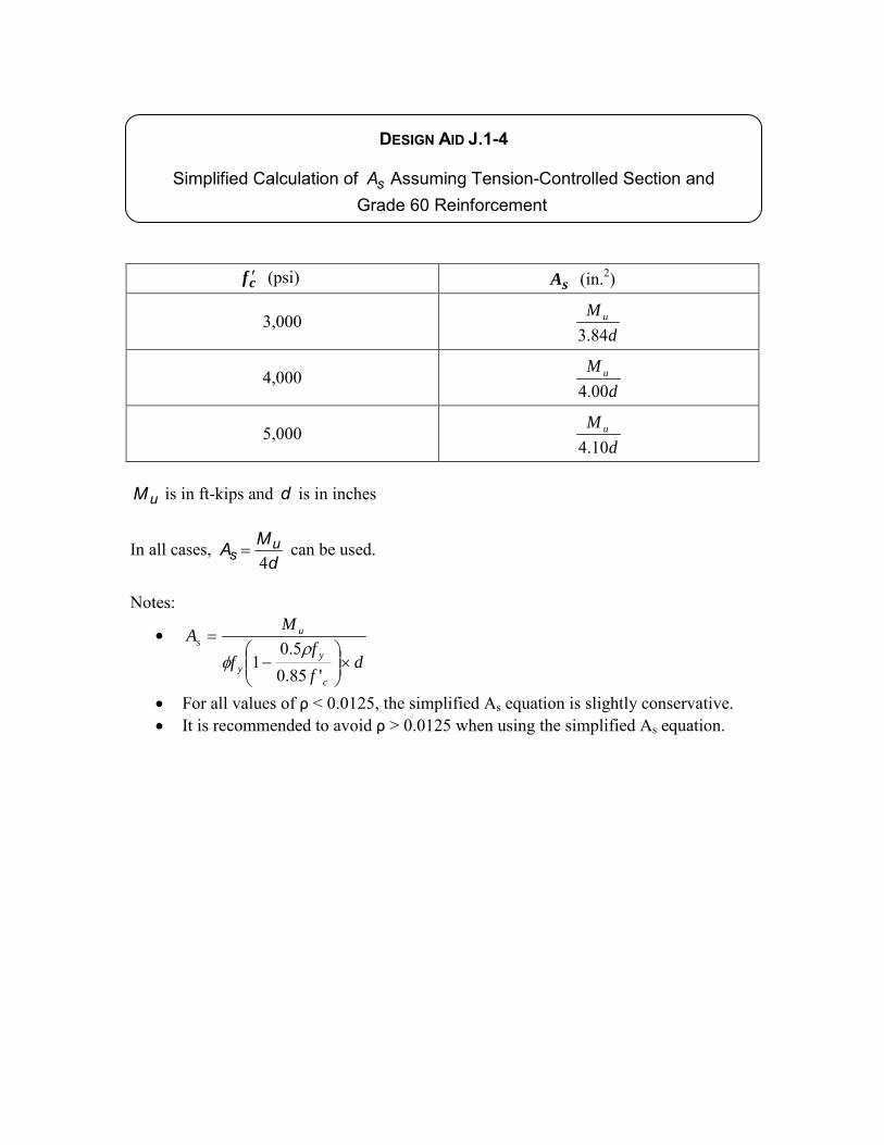
DESIGN AID J.1-4
Simplified Calculation of sA Assuming Tension-Controlled Section and Grade 60 Reinforcement
cf ′ (psi) sA (in.2)
3,000 d
M u
84.3
4,000 d
M u
00.4
5,000 d
M u
10.4
uM is in ft-kips and d is in inches
In all cases, d
MA us 4
= can be used.
Notes:
• d
ff
f
MA
c
yy
us
×
−
=
'85.05.0
1ρ
φ
• For all values of ρ < 0.0125, the simplified As equation is slightly conservative. • It is recommended to avoid ρ > 0.0125 when using the simplified As equation.
pfs
314 Design Aid
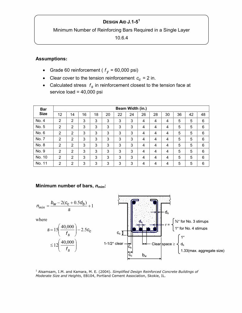
DESIGN AID J.1-51
Assumptions:
yf
cc
sf
Bar Size
Beam Width (in.)
Minimum number of bars, nmim:
1)5.0(2
sdcb
n bcwmin
where
s
cs
f
cf
s
000,4012
5.2000,4015
1 Alsamsam, I.M. and Kamara, M. E. (2004). Simplified Design Reinforced Concrete Buildings of Moderate Size and Heights, EB104, Portland Cement Association, Skokie, IL.
db
pfs
314 Design Aid
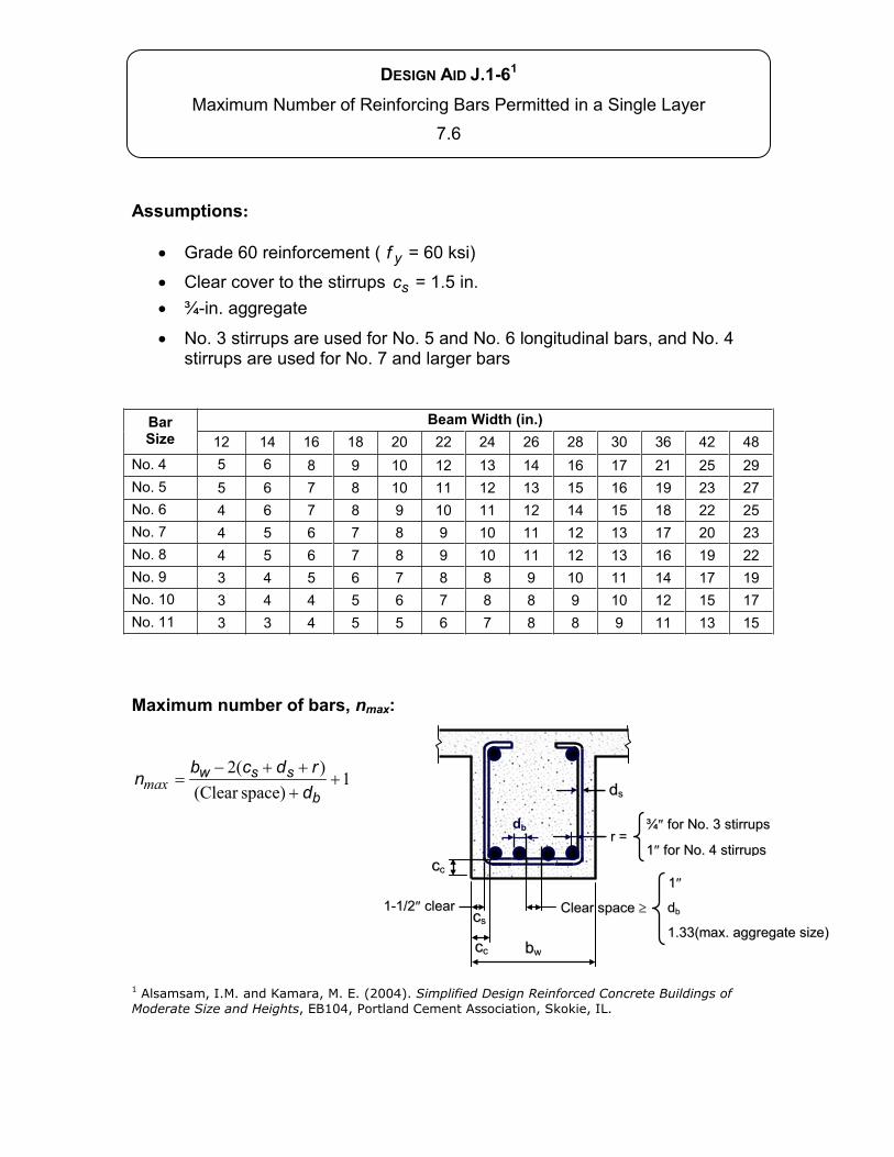
DESIGN AID J.1-61
Assumptions:
yf
sc
Bar Size
Beam Width (in.)
Maximum number of bars, nmax:
1space)(Clear
)(2
b
sswdrdcb
nmax
1 Alsamsam, I.M. and Kamara, M. E. (2004). Simplified Design Reinforced Concrete Buildings of Moderate Size and Heights, EB104, Portland Cement Association, Skokie, IL.
db
pfs
314 Design Aid
1 2 3
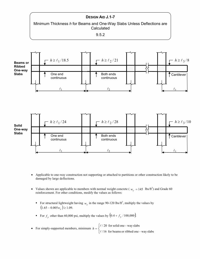
5.18/1h 21/2h 8/3h
1 2 3
24/1h 28/2h 10/3hSolid One-way Slabs
Applicable to one-way construction not supporting or attached to partitions or other construction likely to be damaged by large deflections.
Values shown are applicable to members with normal weight concrete ( 145cw lbs/ft3) and Grade 60 reinforcement. For other conditions, modify the values as follows:
For structural lightweight having cw in the range 90-120 lbs/ft3, multiply the values by .09.1005.065.1 cw
For yf other than 60,000 psi, multiply the values by .000,100/4.0 yf
For simply-supported members, minimum slabsway -one ribbedor beamsfor 16/
slabsway -one solidfor 20/h
Beams or Ribbed One-way Slabs
DESIGN AID J.1-7h
pfs
314 Design Aid
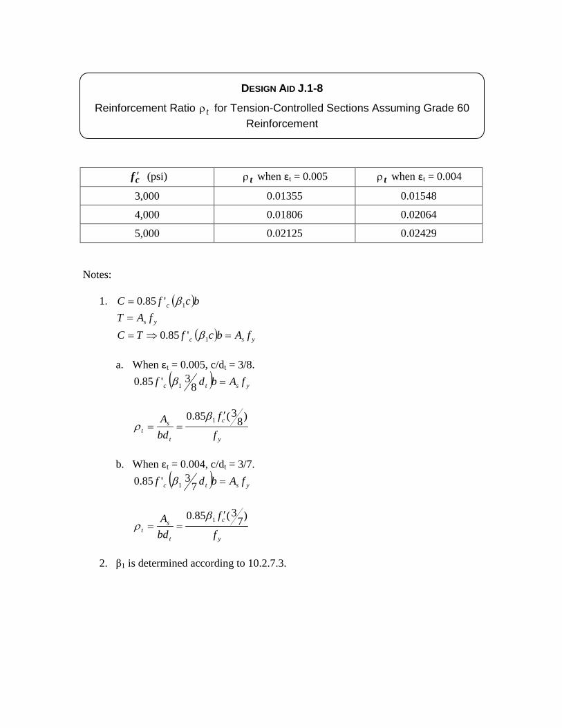
DESIGN AID J.1-8
Reinforcement Ratio tρ for Tension-Controlled Sections Assuming Grade 60 Reinforcement
cf ′ (psi) tρ when εt = 0.005 tρ when εt = 0.004
3,000 0.01355 0.01548
4,000 0.01806 0.02064
5,000 0.02125 0.02429 Notes:
1. ( )bcfC c 1'85.0 β=
ys fAT = ( ) ysc fAbcfTC =⇒= 1'85.0 β
a. When εt = 0.005, c/dt = 3/8.
( ) ystc fAbdf =83'85.0 1β
y
c
t
st f
f
bdA )8
3(85.0 1 ′==
βρ
b. When εt = 0.004, c/dt = 3/7.
( ) ystc fAbdf =73'85.0 1β
y
c
t
st f
f
bdA )7
3(85.0 1 ′==
βρ
2. β1 is determined according to 10.2.7.3.
mrs
Typewritten Text
mrs
Typewritten Text
mrs
Typewritten Text
pfs
314 Design Aid
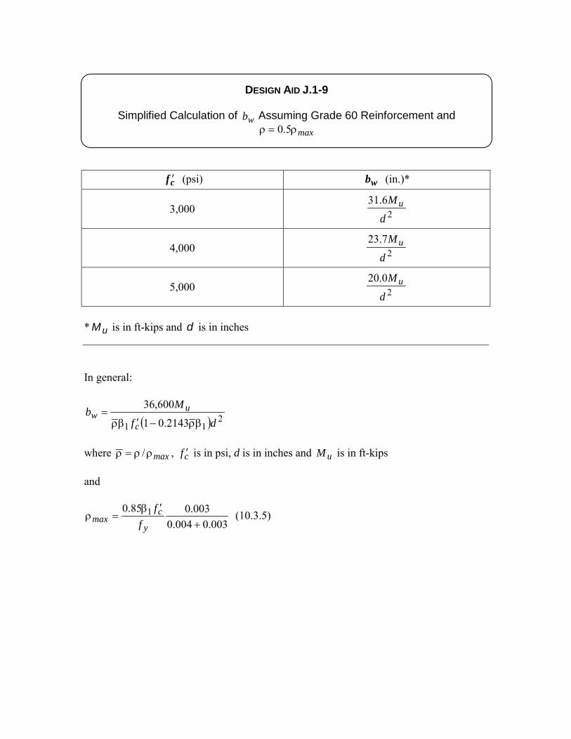
DESIGN AID J.1-9
Simplified Calculation of wb Assuming Grade 60 Reinforcement and maxρ=ρ 5.0
cf ′ (psi) wb (in.)*
3,000 26.31
d
M u
4,000 27.23
d
M u
5,000 20.20
d
M u
* uM is in ft-kips and d is in inches
In general:
( ) 211 2143.01
600,36
df
Mb
c
uw
βρ−′βρ=
where maxρρ=ρ / , cf ′ is in psi, d is in inches and uM is in ft-kips and
003.0004.0003.085.0 1+
′β=ρ
y
cmax f
f (10.3.5)
pfs
314 Design Aid
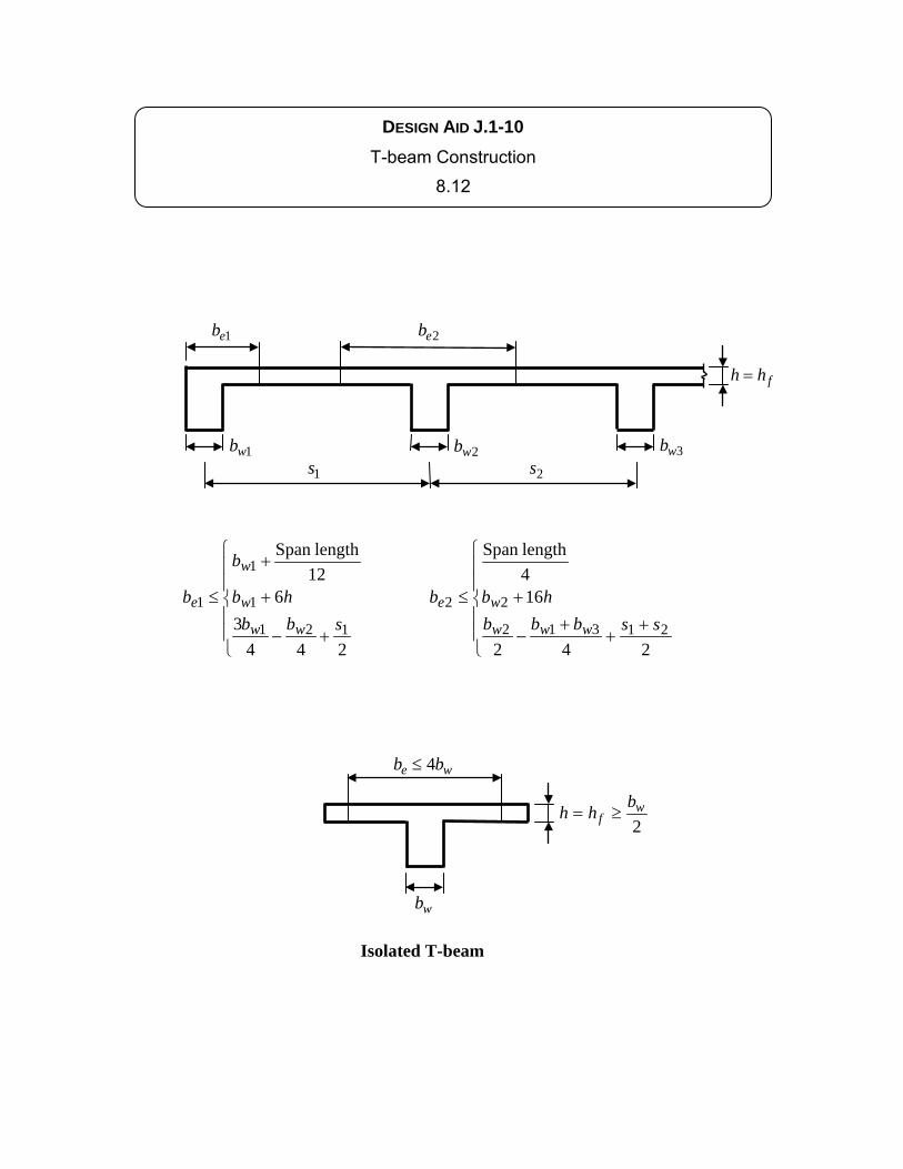
1s
fhh =
+−
+
+
≤
2443
612lengthSpan
121
1
1
1sbb
hb
b
b
ww
w
w
e
1eb
2s 1wb 2wb
2eb
++
+−
+≤
242
164lengthSpan
21312
22ssbbb
hbb
www
we
3wb
2w
fbhh ≥=
wb
we bb 4≤
Isolated T-beam
DESIGN AID J.1-10 T-beam Construction
8.12
pfs
314 Design Aid
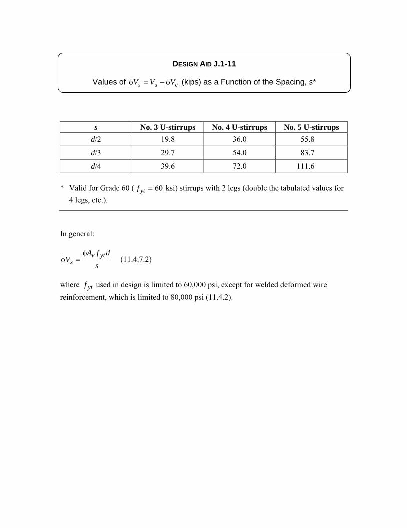
DESIGN AID J.1-11
Values of cus VVV φ−=φ (kips) as a Function of the Spacing, s*
s No. 3 U-stirrups No. 4 U-stirrups No. 5 U-stirrups d/2 19.8 36.0 55.8
d/3 29.7 54.0 83.7
d/4 39.6 72.0 111.6 * Valid for Grade 60 ( 60=ytf ksi) stirrups with 2 legs (double the tabulated values for
4 legs, etc.).
In general:
sdfA
V ytvs
φ=φ (11.4.7.2)
where ytf used in design is limited to 60,000 psi, except for welded deformed wire reinforcement, which is limited to 80,000 psi (11.4.2).
pfs
314 Design Aid
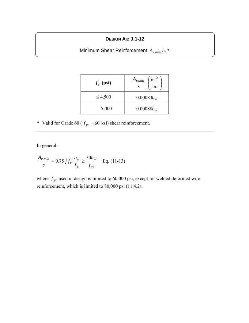
DESIGN AID J.1-12
Minimum Shear Reinforcement */, sA minv
cf ′ (psi) s
A minv,
in.in.2
500,4≤ wb00083.0
5,000 wb00088.0
* Valid for Grade 60 ( 60=ytf ksi) shear reinforcement.
In general:
yt
w
yt
wc
minv
fb
fb
fs
A 5075.0, ≥′= Eq. (11-13)
where ytf used in design is limited to 60,000 psi, except for welded deformed wire reinforcement, which is limited to 80,000 psi (11.4.2).
pfs
314 Design Aid
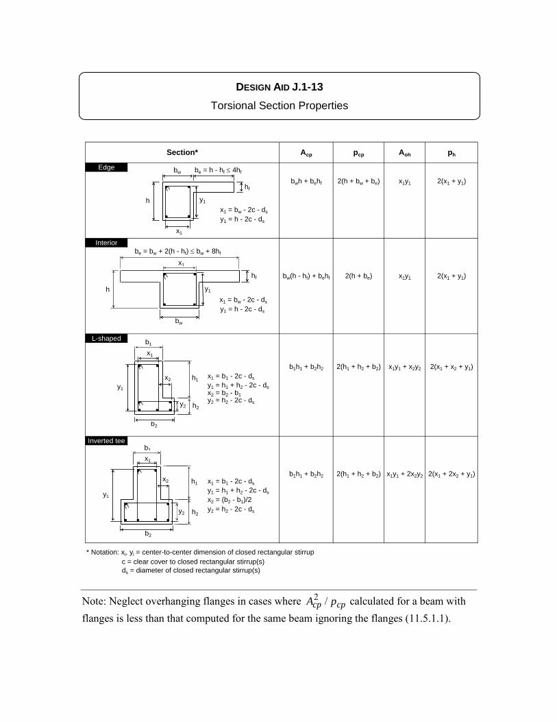
DESIGN AID J.1-13 Torsional Section Properties
Section* Acp pcp Aoh ph
Edge
bwh + behf 2(h + bw + be) x1y1 2(x1 + y1)
x1 = bw - 2c - ds
y1 = h - 2c - ds
Interior
bw(h - hf) + behf 2(h + be) x1y1 2(x1 + y1)
x1 = bw - 2c - ds
y1 = h - 2c - ds
L-shaped
b1h1 + b2h2 2(h1 + h2 + b2) x1y1 + x2y2 2(x1 + x2 + y1)x1 = b1 - 2c - dsy1 = h1 + h2 - 2c - dsx2 = b2 - b1y2 = h2 - 2c - ds
Inverted tee
b1h1 + b2h2 2(h1 + h2 + b2) x1y1 + 2x2y2 2(x1 + 2x2 + y1)x1 = b1 - 2c - dsy1 = h1 + h2 - 2c - ds
x2 = (b2 - b1)/2y2 = h2 - 2c - ds
* Notation: xi, yi = center-to-center dimension of closed rectangular stirrup c = clear cover to closed rectangular stirrup(s) ds = diameter of closed rectangular stirrup(s)
hf
h
hf
yo
yo
xo
h
bw
hf
be = bw + 2(h - hf) ≤ bw + 8hf
h
bw
hf
be = h - hf ≤ 4hf
x1
y1
y1
x1
b1
y1
b1
h1
h2
b2
y1
y2
x1
x2
h1
h2
b2
y2
b1
x1
x2
y1
Note: Neglect overhanging flanges in cases where cpcp pA /2 calculated for a beam with flanges is less than that computed for the same beam ignoring the flanges (11.5.1.1).
pfs
314 Design Aid
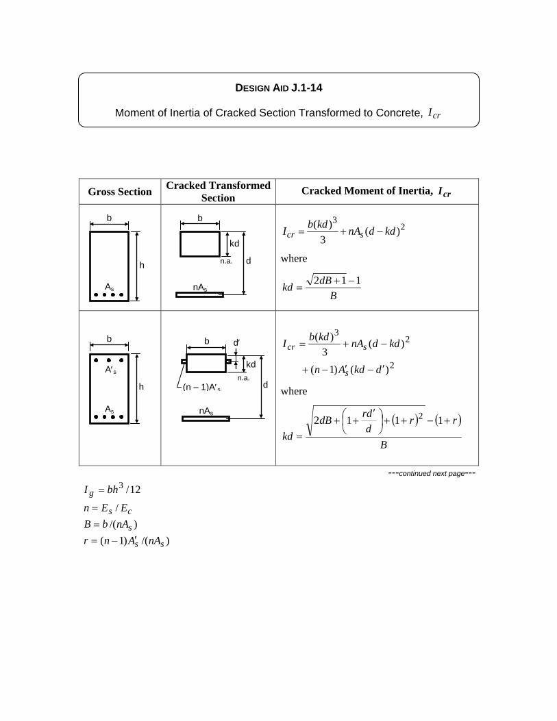
Gross Section Cracked Transformed Section
Cracked Moment of Inertia, crI
23
)(3
)( kddnAkdbI scr −+=
where
BdBkd 112 −+
=
2
23
)()1(
)(3
)(
dkdAn
kddnAkdbI
s
scr
′−′−+
−+=
where
( ) ( )
B
rrddrdB
kd+−++
′
++=
1112 2
---continued next page--- 12/3bhI g =
cs EEn /= )/( snAbB =
)/()1( ss nAAnr ′−=
b
As
A′s
b d′
n.a.
nAs
kd
d
b
n.a.
b
As
DESIGN AID J.1-14
Moment of Inertia of Cracked Section Transformed to Concrete, crI
h
h
nAs
kd
d (n – 1)A′s
pfs
314 Design Aid
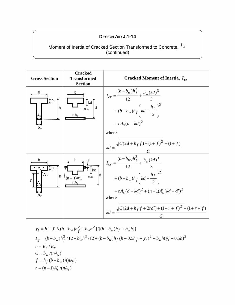
Gross Section Cracked
Transformed Section
Cracked Moment of Inertia, crI
2
2
33
)(
2)(
3)(
12
)(
kddnA
hkdhbb
kdbhbbI
s
ffw
wfwcr
−+
−−+
+−
=
where
C
fffhdCkd
f )1()1()2( 2 +−+++=
22
2
33
)()1()(
2)(
3)(
12
)(
dkdAnkddnA
hkdhbb
kdbhbbI
ss
ffw
wfwcr
′−′−+−+
−−+
+−
=
where
C
frfrdrfhdCkd
f )1()1()22( 2 ++−+++′++=
]})/[(])[(5.0{ 22 hbhbbhbhbbhy wfwwfwt +−+−−=
2233 )5.0()5.0()(12/12/)( hyhbyhhhbbhbhbbI twtffwwfwg −+−−−++−=
cs EEn /= )/( sw nAbC =
)/()( swf nAbbhf −=
)/()1( ss nAAnr ′−=
nAs
kd
b
n.a.
d′ b
As
hf
bw
A′s
nAs
kd d
b
n.a.
b
As
hf
bw
DESIGN AID J.1-14
Moment of Inertia of Cracked Section Transformed to Concrete, crI (continued)
h
h yt
d (n – 1)A′s
pfs
314 Design Aid
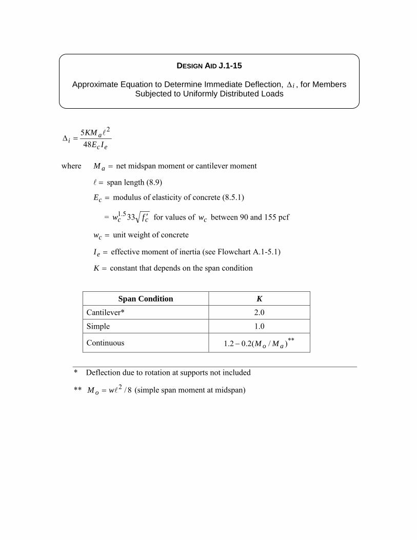
DESIGN AID J.1-15
Approximate Equation to Determine Immediate Deflection, i∆ , for Members Subjected to Uniformly Distributed Loads
ec
ai IE
KM48
5 2=∆
where =aM net midspan moment or cantilever moment
= span length (8.9)
=cE modulus of elasticity of concrete (8.5.1)
= cc fw ′335.1 for values of cw between 90 and 155 pcf
=cw unit weight of concrete
=eI effective moment of inertia (see Flowchart A.1-5.1)
=K constant that depends on the span condition
Span Condition K
Cantilever* 2.0
Simple 1.0
Continuous **)/(2.02.1 ao MM−
* Deflection due to rotation at supports not included
** 8/2wM o = (simple span moment at midspan)
pfs
314 Design Aid
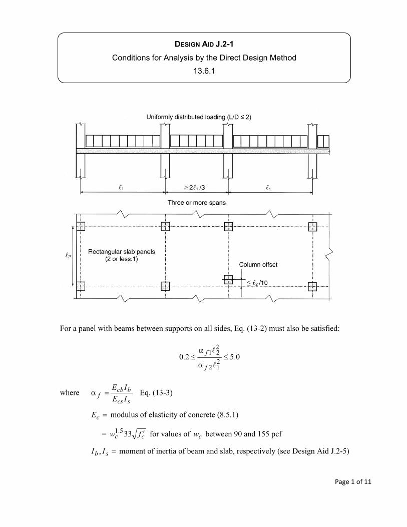
DESIGN AID J.2-1
f
f
scs
bcbf IE
IE
cE
cc fw cw
sb II
Page 1 of 11
pfs
314 Design Aid
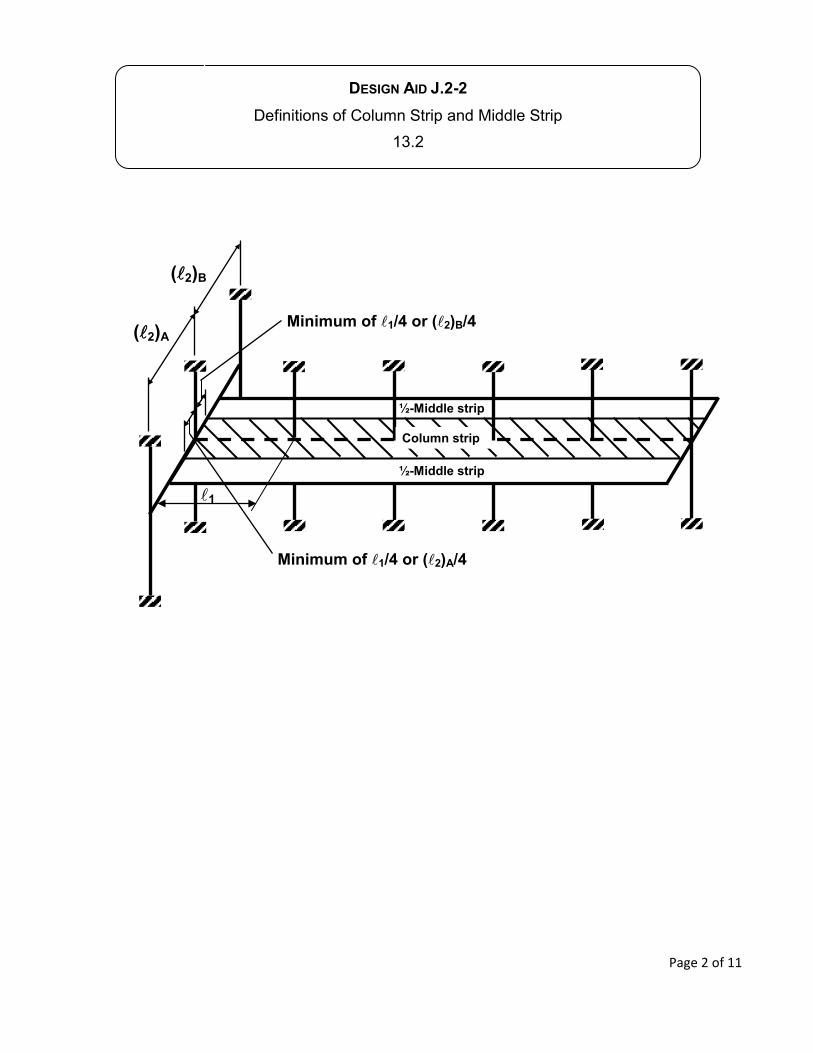
DESIGN AID J.2-2
½-Middle strip
½-Middle strip
1
Column strip
Minimum of 1/4 or ( 2)A/4
Minimum of 1/4 or ( 2)B/4( 2)A
( 2)B
Page 2 of 11
pfs
314 Design Aid
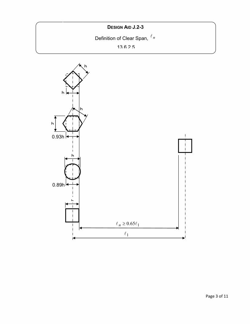
DESIGN AID J.2-3
n
n
Page 3 of 11
pfs
314 Design Aid
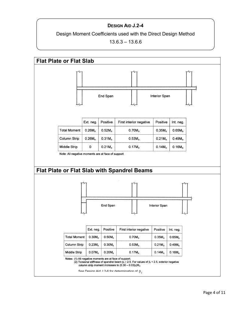
DESIGN AID J.2-4
Flat Plate or Flat Slab
Flat Plate or Flat Slab with Spandrel Beams
t
Page 4 of 11
pfs
314 Design Aid
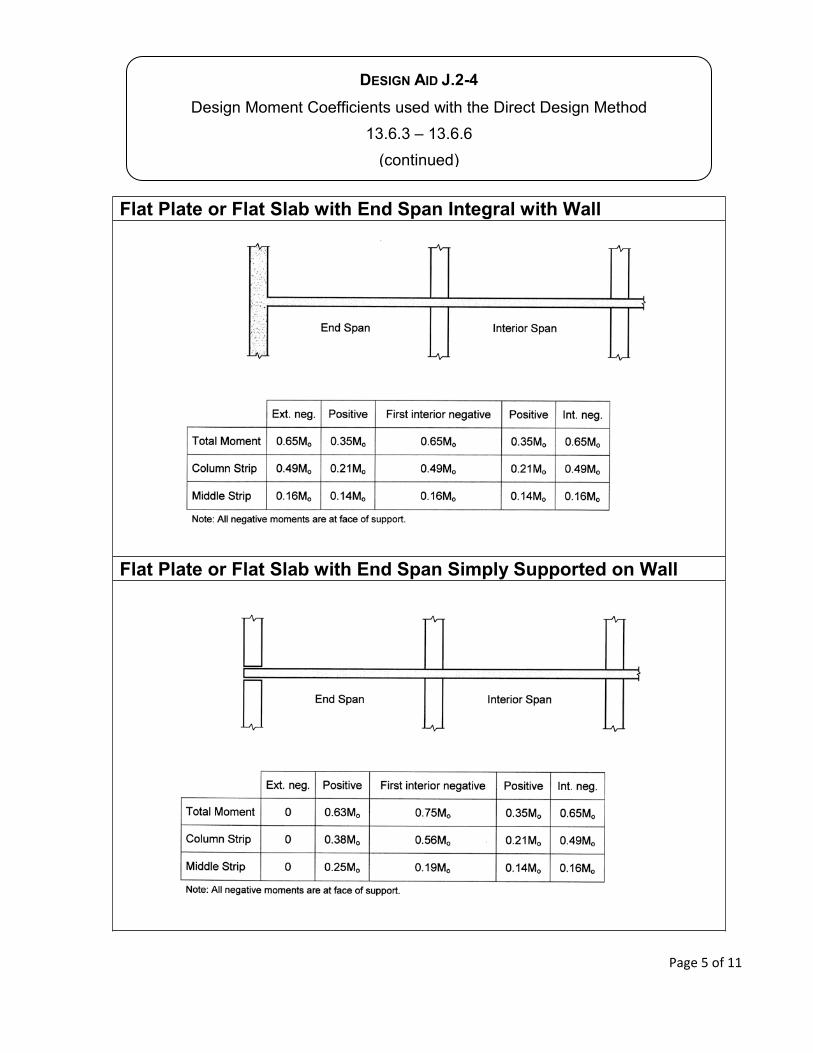
DESIGN AID J.2-4
Flat Plate or Flat Slab with End Span Integral with Wall
Flat Plate or Flat Slab with End Span Simply Supported on Wall
Page 5 of 11
pfs
314 Design Aid
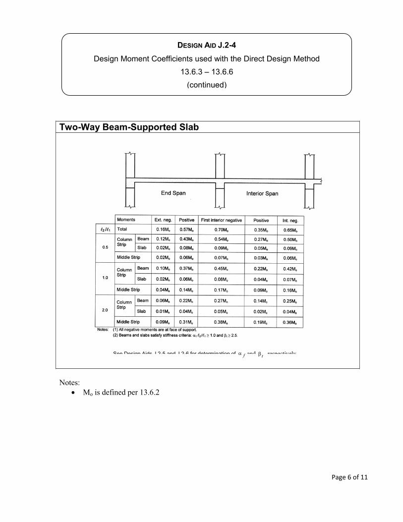
DESIGN AID J.2-4
Two-Way Beam-Supported Slab
f t
Page 6 of 11
pfs
314 Design Aid
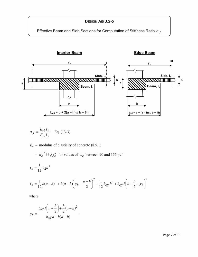
DESIGN AID J.2-5
f
CC2
ha
b
beff = b + 2(a – h) b + 8h
Beam, Ib
Slab, Is
2
ha
b
Beam, Ib
Slab, Is
CL
beff = b + (a – h) b + 4h
Interior Beam Edge Beam
scs
bcbf IE
IE
cE
cc fw cw
hIs
beffeffbb yhahbhbhayhabhabI
habhb
habhahby
eff
eff
b
Page 7 of 11
pfs
314 Design Aid
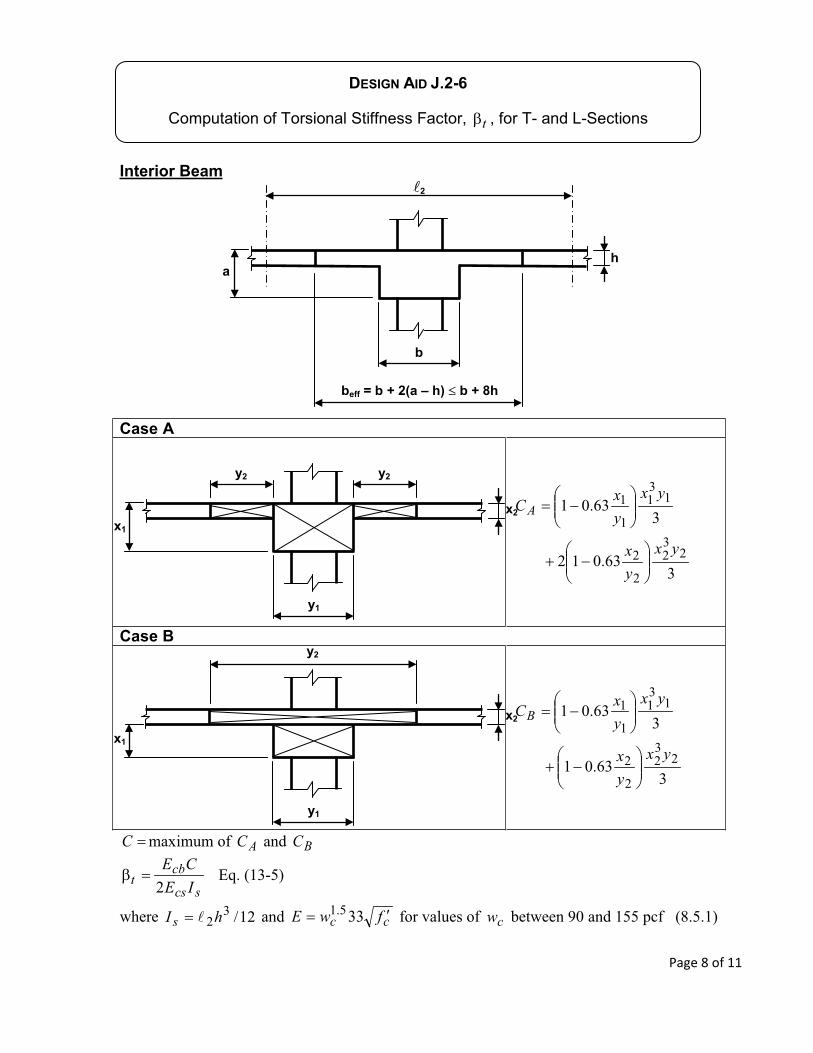
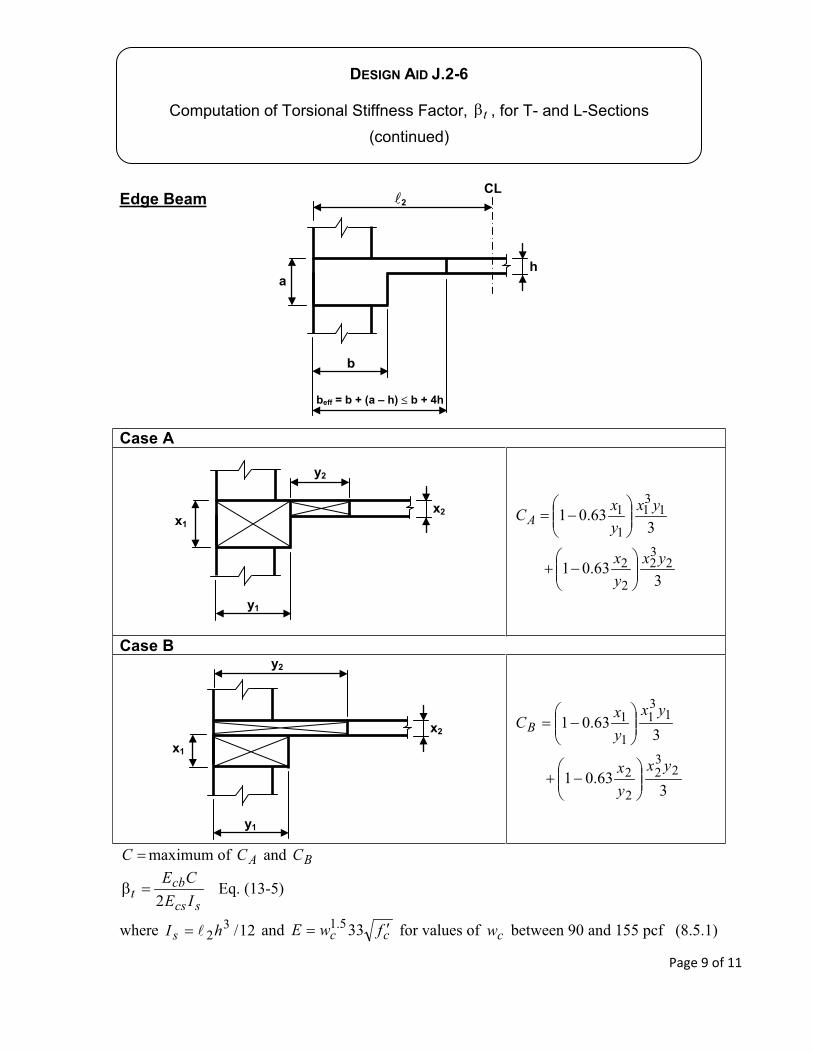
DESIGN AID J.2-6
t
CC2
ha
b
beff = b + 2(a – h) b + 8h
Interior Beam
Case A
yxyx
yxyxCA
Case B
yxyx
yxyxCB
C AC BC
scs
cbt IE
CE
hIs cc fwE cw
x2x1
y1
y2y2
x2
x1
y1
y2
Page 8 of 11
pfs
314 Design Aid
2
ha
b
CL
beff = b + (a – h) b + 4h
DESIGN AID J.2-6
t
Edge Beam
Case A
yxyx
yxyxCA
Case B
yxyx
yxyxCB
C AC BC
scs
cbt IE
CE
hIs cc fwE cw
x2x1
y1
y2
x2
x1
y1
y2
Page 9 of 11
pfs
314 Design Aid
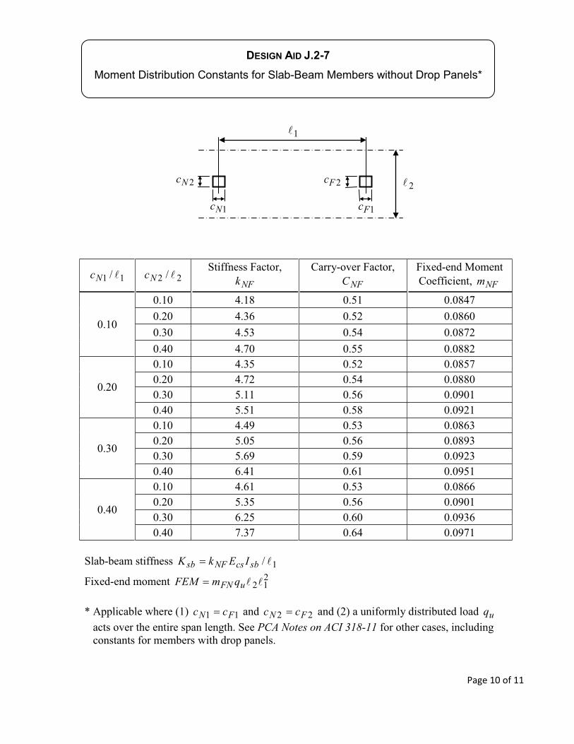
DESIGN AID J.2-7
Nc NcNFk NFC NFm
sbcsNFsb IEkK
uFN qmFEM
FN cc FN cc uqPCA Notes on ACI 318-11
Nc
Nc
Fc
Fc
Page 10 of 11
pfs
314 Design Aid
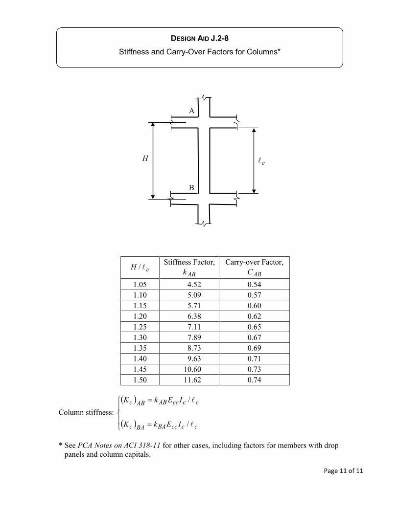
DESIGN AID J.2-8
cHABk ABC
ccccBABAc
ccccABABc
IEkK
IEkK
PCA Notes on ACI 318-11
H c
Page 11 of 11
pfs
314 Design Aid