
DEPT. OF ELECTRICAL AND ELECTRONICS ENGINEERING …eem.eskisehir.edu.tr/eem471files/exp/exp1.pdf ·...
10
EEM471 ELECTRICAL MACHINERY LABORATORY / EXPERIMENT I 1 Instructor: Assist. Prof. Dr. Şener AGALAR TA: Res. Asst. H. Ersin EROL Res. Asst. Mustafa DEMİRTAŞ Res. Asst. Hasan İZMİTLİGİL DEPT. OF ELECTRICAL AND ELECTRONICS ENGINEERING 2018-2019 FALL EEM 471 ELECTRICAL MACHINERY LABORATORY EXPERIMENT I • Measuring the Stator Resistance of a 3Φ Asynchronous Motor • Measuring the Rotor Resistance of a 3Φ Asynchronous Motor • Transformation ratio of Stator / Rotor • Transformation ratio of Rotor / Stator
Transcript of DEPT. OF ELECTRICAL AND ELECTRONICS ENGINEERING …eem.eskisehir.edu.tr/eem471files/exp/exp1.pdf ·...

EEM471 ELECTRICAL MACHINERY LABORATORY / EXPERIMENT I 1
Instructor: Assist. Prof. Dr. Şener AGALAR
TA: Res. Asst. H. Ersin EROL
Res. Asst. Mustafa DEMİRTAŞ
Res. Asst. Hasan İZMİTLİGİL
DEPT. OF ELECTRICAL AND ELECTRONICS
ENGINEERING
2018-2019 FALL
EEM 471 ELECTRICAL MACHINERY
LABORATORY
EXPERIMENT I
• Measuring the Stator Resistance of a 3Φ Asynchronous Motor
• Measuring the Rotor Resistance of a 3Φ Asynchronous Motor
• Transformation ratio of Stator / Rotor
• Transformation ratio of Rotor / Stator

EEM471 ELECTRICAL MACHINERY LABORATORY / EXPERIMENT I 2
RATED CHARACTERISTICS OF THE MACHINE UNDER TEST
Before starting to discuss the execution of the individual tests, it is useful to fully exam-
ine the rated characteristics of the machine under test. These data, reported on a plate, represent
the "Identity Card" that every manufacturer fixes on its machines, so that who will use them will
be able to recognize their most important operating features.
These rated values, of course, are the result of tests that the manufacturer has performed on sev-
eral prototypes at the beginning of the series production; each manufactured machine may show
performances which are slightly different from the rated values, due to the unavoidable manufac-
turing tolerances.
To perform the checking test on a series machine, therefore, is to verify when the stand-
ard performances reported on the plate are really respected and to detect those special operating
characteristics that, though not reported on the plate, are nevertheless important for the practical
use of the machine.
TEST NO: 1
MEASURING THE STATOR AND ROTOR WINDING RESISTANCES
The value of the stator and rotor winding resistances in the induction motor are useful to
calculate:
• the conventional efficiency
• torques and slips under load (through the drawing of the circular diagram).
Being the three-phase induction motor, its stator winding is constituted by three separate circuits
(U, V, W), while the rotor windings are star connected (phases K, L, M), whose terminals are
reported on the terminal board according to the following diagram:
The three phases may be either star or delta interconnected in a very simple way, as the follow-
ing diagrams show:
rotor winding
stator winding

EEM471 ELECTRICAL MACHINERY LABORATORY / EXPERIMENT I 3
STAR CONNECTION DELTA CONNECTION
Being the three stator phases designed for the rated current, they have a rather small re-
sistance (the value is proportionally smaller for greater machines). Therefore, it is necessary to
follow the required contrivances to avoid the influence of the contact resistances both selecting a
suitable measuring method and adequately wiring the voltmetric connections in the circuit itself.
Obviously, the measurement has to be performed in DC current and with steady machine; in any
case, it is necessary to act on "cold" machine, i.e. not operating since several hours, to be sure
that every part of it has a temperature equal to the room temperature. In this case, when the
measuring method will not produce an appreciable heating, it will be possible to say that the
measured resistance values are referred to a winding temperature equal to the room temperature
(which may be easily measured with a common thermometer).
ELECTRICAL DIAGRAM NO: 1 Stator Resistance
Among the several available methods, we will choose, for greater convenience, the volt-
ampere method.
To avoid warming the windings, the test current is limited to 10% of the rated phase cur-
rent thus reading the rated current value from data plate
Ifn = .........
The max test current shall be Ipmax = 0.1 Ifn = .........
- o
EEM471 ELECTRICAL MACHINERY LABORATORY / EXPERIMENT I 4
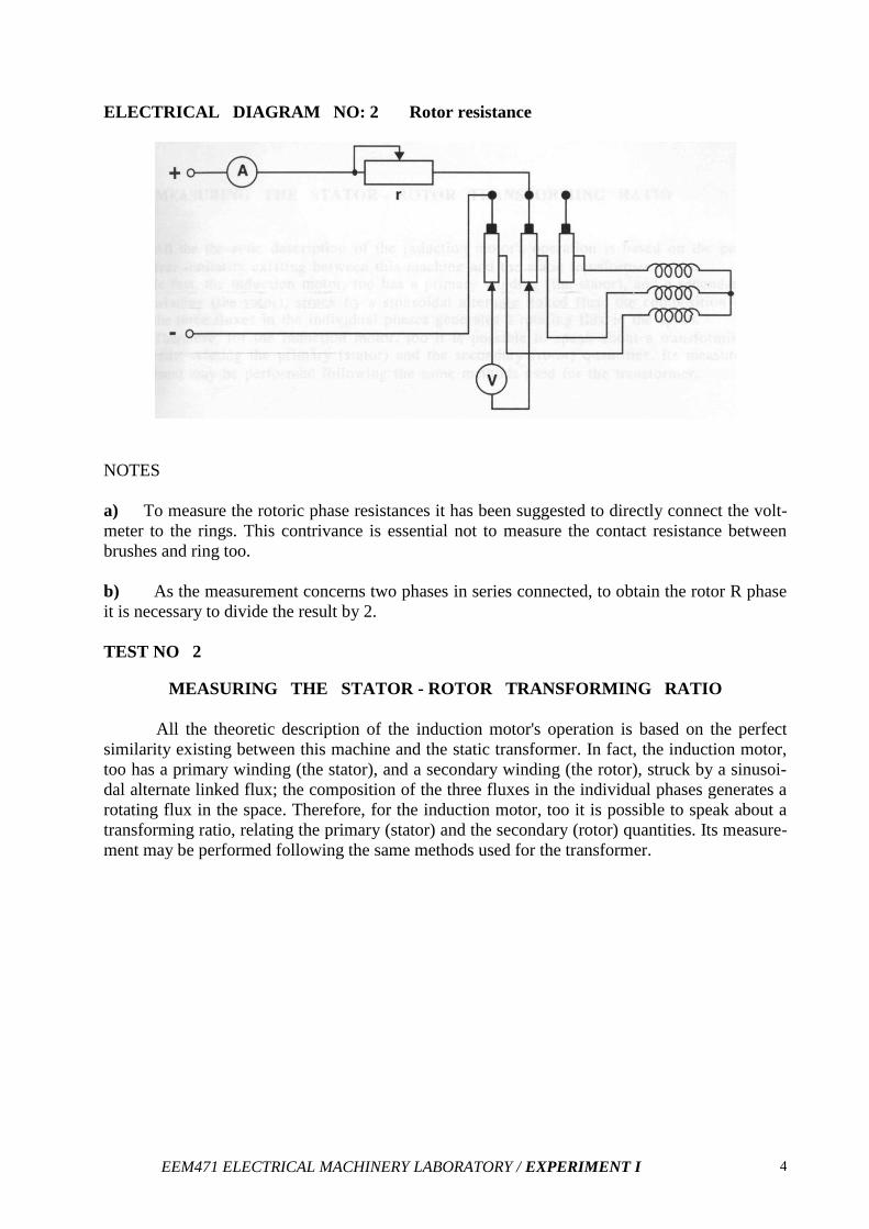
ELECTRICAL DIAGRAM NO: 2 Rotor resistance
NOTES
a) To measure the rotoric phase resistances it has been suggested to directly connect the volt-
meter to the rings. This contrivance is essential not to measure the contact resistance between
brushes and ring too.
b) As the measurement concerns two phases in series connected, to obtain the rotor R phase
it is necessary to divide the result by 2.
TEST NO 2
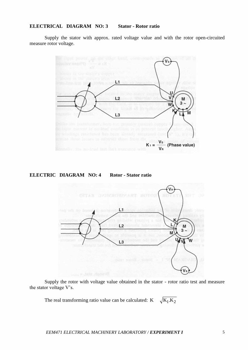
MEASURING THE STATOR - ROTOR TRANSFORMING RATIO
All the theoretic description of the induction motor's operation is based on the perfect
similarity existing between this machine and the static transformer. In fact, the induction motor,
too has a primary winding (the stator), and a secondary winding (the rotor), struck by a sinusoi-
dal alternate linked flux; the composition of the three fluxes in the individual phases generates a
rotating flux in the space. Therefore, for the induction motor, too it is possible to speak about a
transforming ratio, relating the primary (stator) and the secondary (rotor) quantities. Its measure-
ment may be performed following the same methods used for the transformer.
EEM471 ELECTRICAL MACHINERY LABORATORY / EXPERIMENT I 5
ELECTRICAL DIAGRAM NO: 3 Stator - Rotor ratio
Supply the stator with approx. rated voltage value and with the rotor open-circuited
measure rotor voltage.
ELECTRIC DIAGRAM NO: 4 Rotor - Stator ratio
Supply the rotor with voltage value obtained in the stator - rotor ratio test and measure
the stator voltage V’s.
The real transforming ratio value can be calculated: 1 2K K .K

EEM471 ELECTRICAL MACHINERY LABORATORY / EXPERIMENT I 6
PRACTICAL TEST NO: la STATOR RESISTANCE
PRACTICAL DIAGRAM
OPERATION SEQUENCE
Build the circuit in heavy drawn that is shown in the diagram:
1 - Preset the control in the module;
VARIABLE DC OUTPUT
EXCITATION RHEOSTAT
Variac completely counter
clock-wise rotated
"R” completely counter clock-
wise rotated
2 - Activate the power supply and close the switch.
3 - Adjust the variac and "R" to obtain a current of approximately 0.2 A.
4 - Directly insert the voltmeter to the asynchronous motor terminals.
5 - Read the values on the voltmeter and on the ampere-meter.
6 - Disconnect the voltmeter and open the switch of variable DC output.
7 - Repeat the steps 2&3 after having inserted in the measuring circuit successively into the V
phase and the W phase.

EEM471 ELECTRICAL MACHINERY LABORATORY / EXPERIMENT I 7
TABLE
Phase Ampermeter (A) Voltmeter (V) Rphase (Ω) Mean Rphase (Ω)
U
V
W
PRACTICAL TEST NO: 1b ROTOR RESISTANCE
PRACTICAL DIAGRAM
OPERATION SEQUENCE
Perform the operations already described in steps 1 to 6 for the measurement of the stator
phases, taking care to directly connect the voltmeter on the rotor rings, downstream the brushes.
EEM471 ELECTRICAL MACHINERY LABORATORY / EXPERIMENT I 8
TABLE:
Phases
Ampermeter (A) Voltmeter (V) Rphase (Ω) Mean Rphase (Ω)
K-L
L-M
M-K
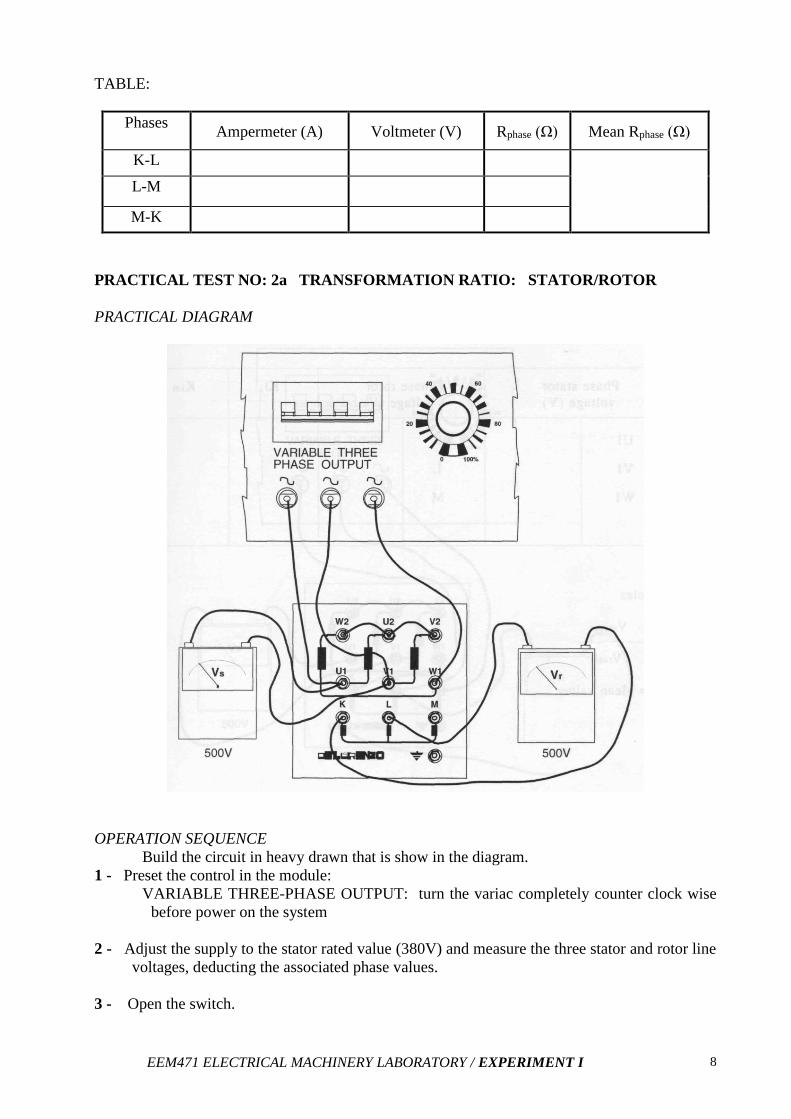
PRACTICAL TEST NO: 2a TRANSFORMATION RATIO: STATOR/ROTOR
PRACTICAL DIAGRAM
OPERATION SEQUENCE
Build the circuit in heavy drawn that is show in the diagram.
1 - Preset the control in the module:
VARIABLE THREE-PHASE OUTPUT: turn the variac completely counter clock wise
before power on the system
2 - Adjust the supply to the stator rated value (380V) and measure the three stator and rotor line
voltages, deducting the associated phase values.
3 - Open the switch.
EEM471 ELECTRICAL MACHINERY LABORATORY / EXPERIMENT I 9
TABLE:
Stator Voltage (V)
Rotor Voltage (V)
K1
K1m
Ul – V1
K-L
V1 – W1
L-M
Wl- U1
M-K
Formulas:
stator1 1m
rotor
VK K MeanValue
V
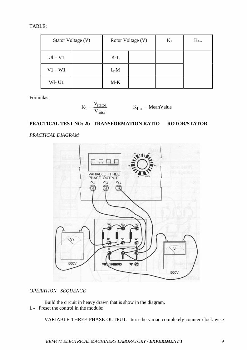
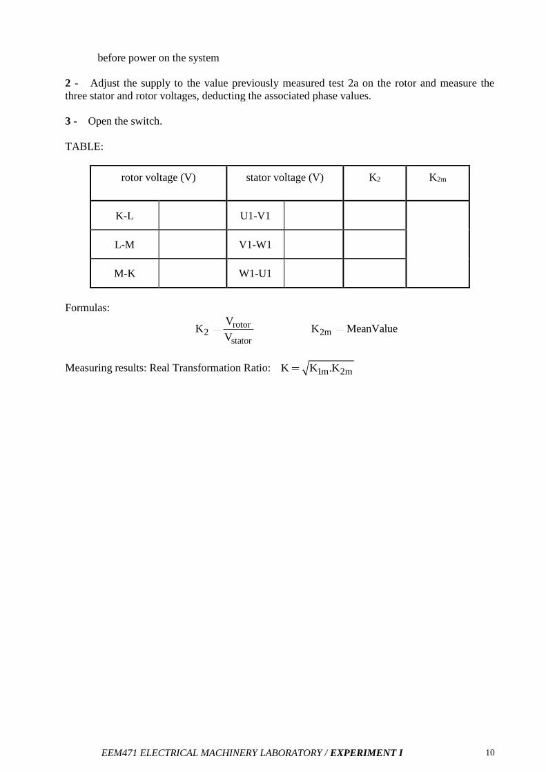
PRACTICAL TEST NO: 2b TRANSFORMATION RATIO ROTOR/STATOR
PRACTICAL DIAGRAM
OPERATION SEQUENCE
Build the circuit in heavy drawn that is show in the diagram.
1 - Preset the control in the module:
VARIABLE THREE-PHASE OUTPUT: turn the variac completely counter clock wise
EEM471 ELECTRICAL MACHINERY LABORATORY / EXPERIMENT I 10
before power on the system
2 - Adjust the supply to the value previously measured test 2a on the rotor and measure the
three stator and rotor voltages, deducting the associated phase values.
3 - Open the switch.
TABLE:
rotor voltage (V)
stator voltage (V)
K2
K2m
K-L
U1-V1
L-M
V1-W1
M-K
W1-U1
Formulas:
rotor2 2m
stator
VK K MeanValue
V
Measuring results: Real Transformation Ratio: 1m 2mK K .K


![Electricity - Physics · (ii) a voltmeter connected to measure the potential difference across R. [2] (c) (i) ... In another experiment, the girl uses two table-tennis balls A and](https://static.fdocument.org/doc/165x107/60992337dce964266e5415ba/electricity-physics-ii-a-voltmeter-connected-to-measure-the-potential-difference.jpg)