Delomatic 4 DM-4 Land/DM-4 Marine
22
DM-4 Land/DM-4 Marine 4189232129C Part 2: Technical Specifications DEIF A/S Page 1 of 22 Delomatic 4 DM-4 Land/DM-4 Marine Document no.: 4189232129C Technical Specifications Part 2, chapter 29
Transcript of Delomatic 4 DM-4 Land/DM-4 Marine
DM-4 Land/DM-4 Marine 4189232129C Part 2: Technical Specifications
DEIF A/S Page 1 of 22
Delomatic 4DM-4 Land/DM-4 Marine
Document no.: 4189232129C
Technical SpecificationsPart 2, chapter 29
DM-4 Land/DM-4 Marine 4189232129C Part 2: Technical Specifications
DEIF A/S Page 2 of 22
Table of contents
29. TECHNICAL SPECIFICATIONS ............................................................................................3 DU AND AOP...............................................................................................................................3 POWER CONTROL MODULE 4.1 (PCM 4.1)....................................................................................8 INPUT OUTPUT MODULE 4.1 (IOM 4.1)........................................................................................13 SYNCHRONISING MODULE 4.1 (SCM 4.1)....................................................................................16 SYNCHRONISING MODULE 4.2 (SCM 4.2)....................................................................................19
DM-4 Land/DM-4 Marine 4189232129C Part 2: Technical Specifications
DEIF A/S Page 3 of 22
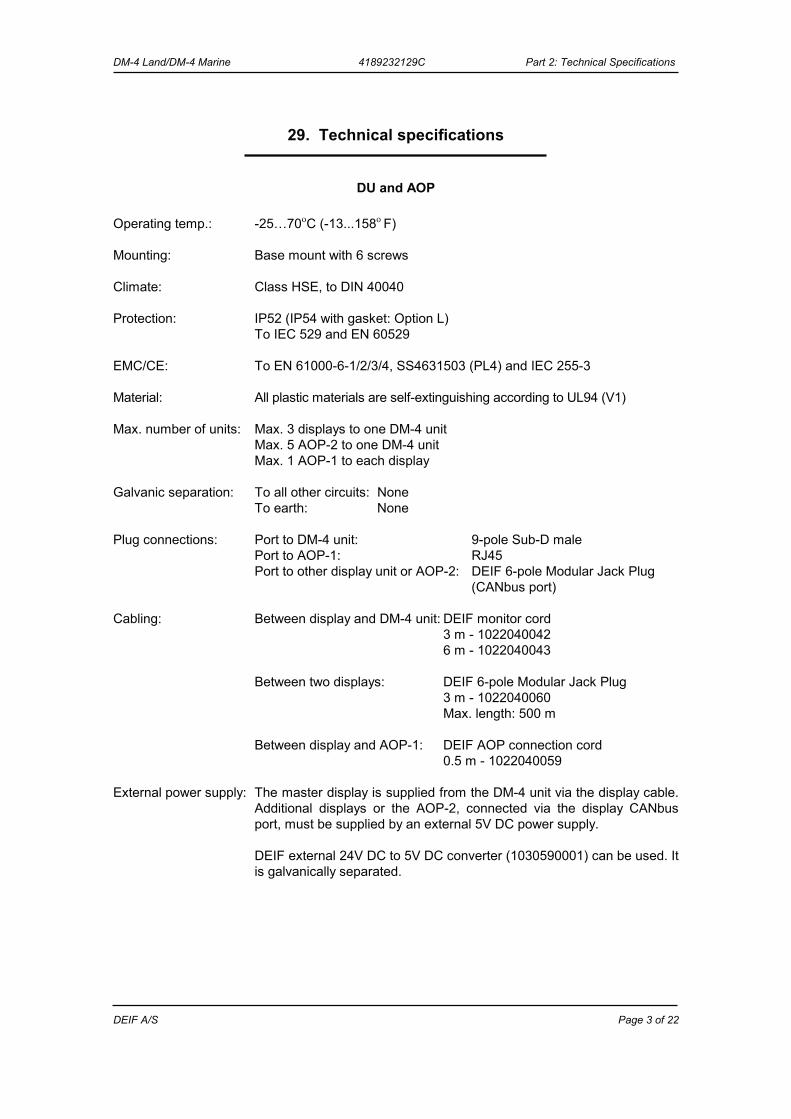
29. Technical specifications
DU and AOP Operating temp.: -25…70οC (-13...158ο F) Mounting: Base mount with 6 screws Climate: Class HSE, to DIN 40040 Protection: IP52 (IP54 with gasket: Option L) To IEC 529 and EN 60529 EMC/CE: To EN 61000-6-1/2/3/4, SS4631503 (PL4) and IEC 255-3 Material: All plastic materials are self-extinguishing according to UL94 (V1) Max. number of units: Max. 3 displays to one DM-4 unit Max. 5 AOP-2 to one DM-4 unit Max. 1 AOP-1 to each display Galvanic separation: To all other circuits: None To earth: None Plug connections: Port to DM-4 unit: 9-pole Sub-D male Port to AOP-1: RJ45 Port to other display unit or AOP-2: DEIF 6-pole Modular Jack Plug
(CANbus port) Cabling: Between display and DM-4 unit: DEIF monitor cord 3 m - 1022040042 6 m - 1022040043 Between two displays: DEIF 6-pole Modular Jack Plug 3 m - 1022040060 Max. length: 500 m Between display and AOP-1: DEIF AOP connection cord 0.5 m - 1022040059 External power supply: The master display is supplied from the DM-4 unit via the display cable.
Additional displays or the AOP-2, connected via the display CANbus port, must be supplied by an external 5V DC power supply.
DEIF external 24V DC to 5V DC converter (1030590001) can be used. It
is galvanically separated.
DM-4 Land/DM-4 Marine 4189232129C Part 2: Technical Specifications
DEIF A/S Page 4 of 22
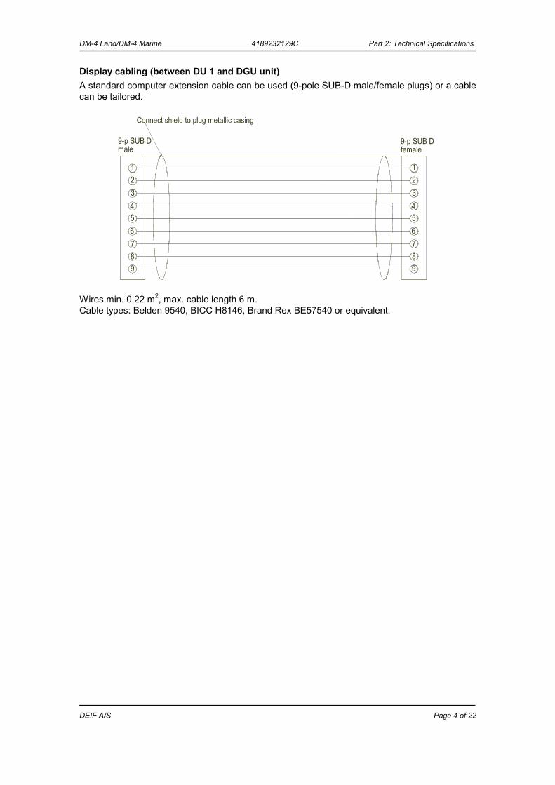
Display cabling (between DU 1 and DGU unit) A standard computer extension cable can be used (9-pole SUB-D male/female plugs) or a cable can be tailored.
Wires min. 0.22 m2, max. cable length 6 m. Cable types: Belden 9540, BICC H8146, Brand Rex BE57540 or equivalent.
DM-4 Land/DM-4 Marine 4189232129C Part 2: Technical Specifications
DEIF A/S Page 5 of 22
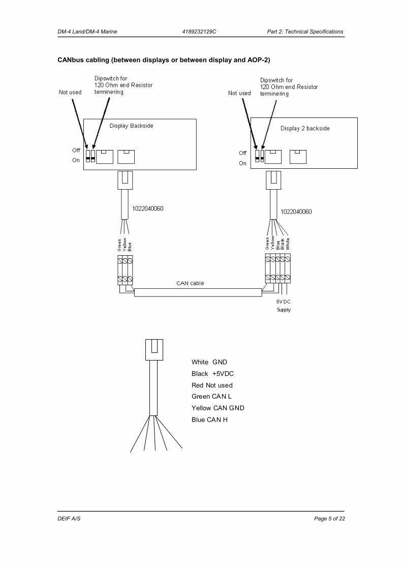
CANbus cabling (between displays or between display and AOP-2)
White GND
Black +5VDC
Red Not usedGreen CAN L
Yellow CAN GND
Blue CAN H
DM-4 Land/DM-4 Marine 4189232129C Part 2: Technical Specifications
DEIF A/S Page 6 of 22
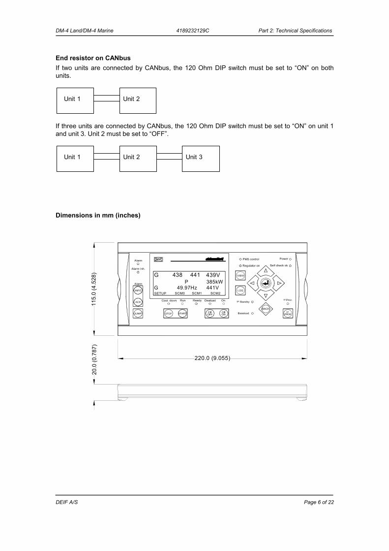
End resistor on CANbus If two units are connected by CANbus, the 120 Ohm DIP switch must be set to “ON” on both units.
Unit 1 Unit 2
If three units are connected by CANbus, the 120 Ohm DIP switch must be set to “ON” on unit 1 and unit 3. Unit 2 must be set to “OFF”.
Unit 1 Unit 2 Unit 3
Dimensions in mm (inches)
441P
SCM2441V385kW
49.97HzSETUPG
G 438 439V
SCM1SCM0
20.0
(0.7
87)
115.
0 (4
.528
)
220.0 (9.055)
DM-4 Land/DM-4 Marine 4189232129C Part 2: Technical Specifications
DEIF A/S Page 7 of 22
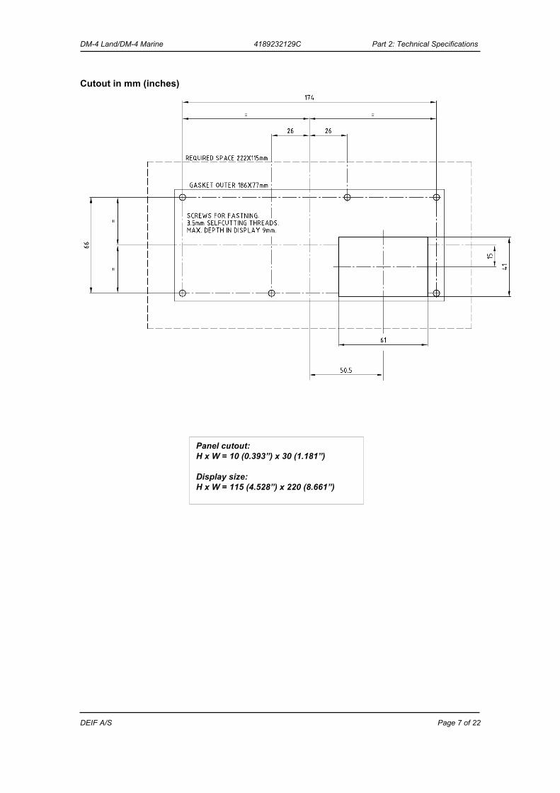
Cutout in mm (inches)
Panel cutout: H x W = 10 (0.393”) x 30 (1.181”) Display size: H x W = 115 (4.528”) x 220 (8.661”)
DM-4 Land/DM-4 Marine 4189232129C Part 2: Technical Specifications
DEIF A/S Page 8 of 22
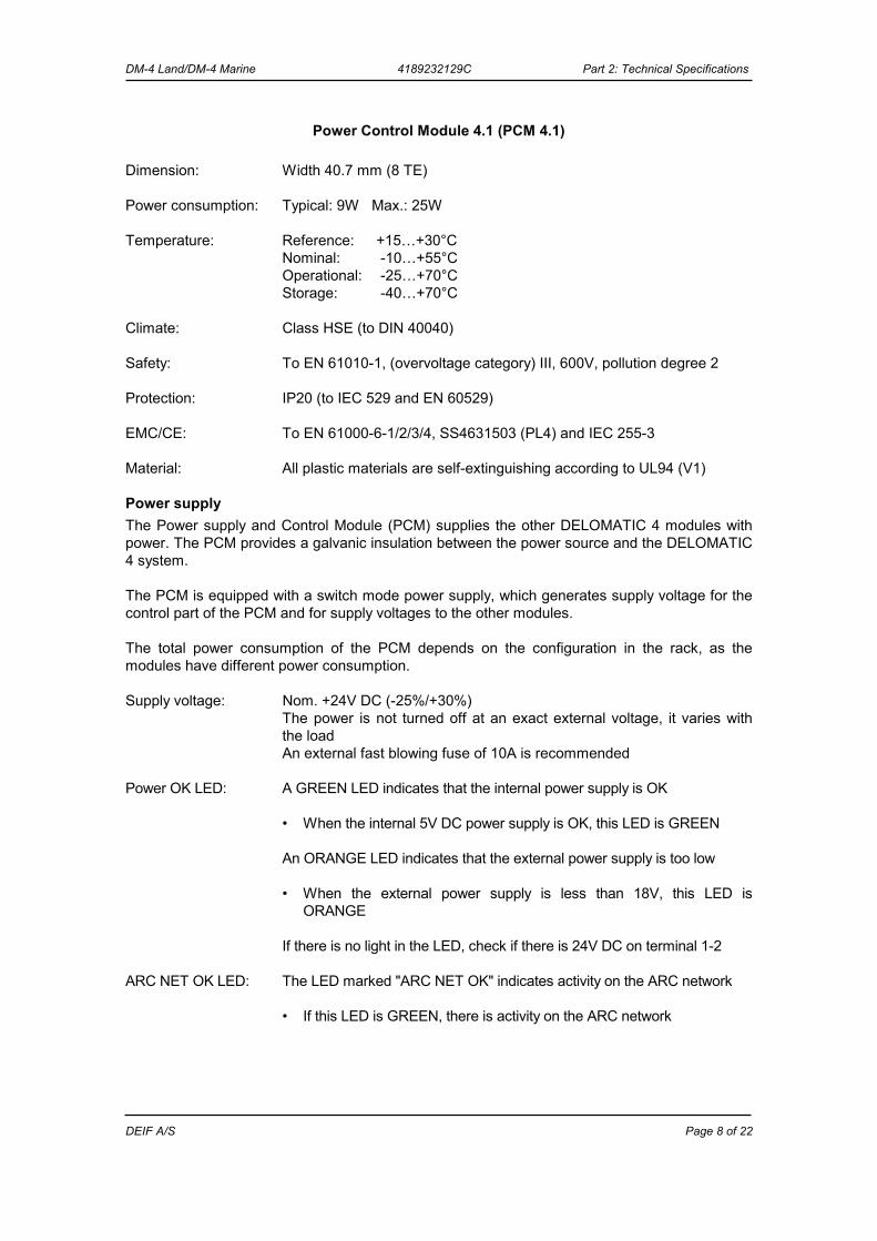
Power Control Module 4.1 (PCM 4.1) Dimension: Width 40.7 mm (8 TE) Power consumption: Typical: 9W Max.: 25W Temperature: Reference: +15…+30°C Nominal: -10…+55°C Operational: -25…+70°C Storage: -40…+70°C Climate: Class HSE (to DIN 40040) Safety: To EN 61010-1, (overvoltage category) III, 600V, pollution degree 2 Protection: IP20 (to IEC 529 and EN 60529) EMC/CE: To EN 61000-6-1/2/3/4, SS4631503 (PL4) and IEC 255-3 Material: All plastic materials are self-extinguishing according to UL94 (V1)
Power supply The Power supply and Control Module (PCM) supplies the other DELOMATIC 4 modules with power. The PCM provides a galvanic insulation between the power source and the DELOMATIC 4 system. The PCM is equipped with a switch mode power supply, which generates supply voltage for the control part of the PCM and for supply voltages to the other modules. The total power consumption of the PCM depends on the configuration in the rack, as the modules have different power consumption. Supply voltage: Nom. +24V DC (-25%/+30%) The power is not turned off at an exact external voltage, it varies with
the load An external fast blowing fuse of 10A is recommended Power OK LED: A GREEN LED indicates that the internal power supply is OK • When the internal 5V DC power supply is OK, this LED is GREEN An ORANGE LED indicates that the external power supply is too low
• When the external power supply is less than 18V, this LED is ORANGE
If there is no light in the LED, check if there is 24V DC on terminal 1-2 ARC NET OK LED: The LED marked "ARC NET OK" indicates activity on the ARC network • If this LED is GREEN, there is activity on the ARC network
DM-4 Land/DM-4 Marine 4189232129C Part 2: Technical Specifications
DEIF A/S Page 9 of 22
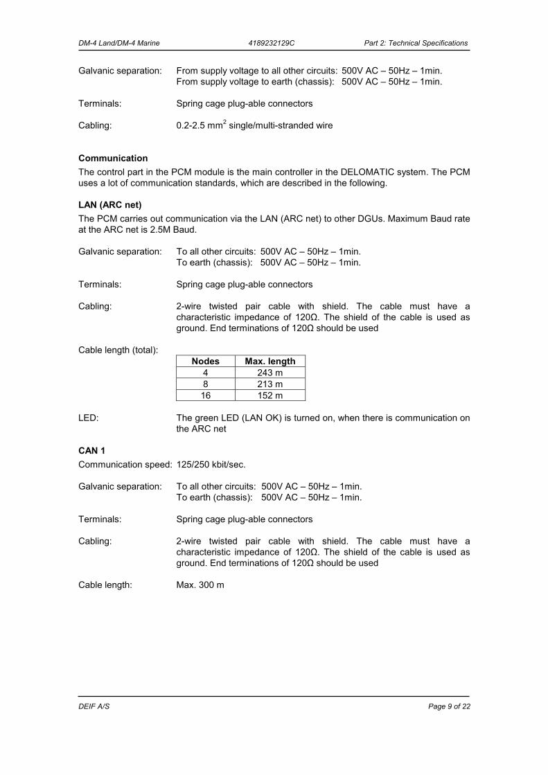
Galvanic separation: From supply voltage to all other circuits: 500V AC – 50Hz – 1min. From supply voltage to earth (chassis): 500V AC – 50Hz – 1min. Terminals: Spring cage plug-able connectors Cabling: 0.2-2.5 mm2 single/multi-stranded wire
Communication The control part in the PCM module is the main controller in the DELOMATIC system. The PCM uses a lot of communication standards, which are described in the following.
LAN (ARC net) The PCM carries out communication via the LAN (ARC net) to other DGUs. Maximum Baud rate at the ARC net is 2.5M Baud. Galvanic separation: To all other circuits: 500V AC – 50Hz – 1min. To earth (chassis): 500V AC – 50Hz – 1min. Terminals: Spring cage plug-able connectors Cabling: 2-wire twisted pair cable with shield. The cable must have a
characteristic impedance of 120Ω. The shield of the cable is used as ground. End terminations of 120Ω should be used
Cable length (total):
Nodes Max. length 4 243 m 8 213 m 16 152 m
LED: The green LED (LAN OK) is turned on, when there is communication on
the ARC net
CAN 1 Communication speed: 125/250 kbit/sec. Galvanic separation: To all other circuits: 500V AC – 50Hz – 1min. To earth (chassis): 500V AC – 50Hz – 1min. Terminals: Spring cage plug-able connectors Cabling: 2-wire twisted pair cable with shield. The cable must have a
characteristic impedance of 120Ω. The shield of the cable is used as ground. End terminations of 120Ω should be used
Cable length: Max. 300 m
DM-4 Land/DM-4 Marine 4189232129C Part 2: Technical Specifications
DEIF A/S Page 10 of 22
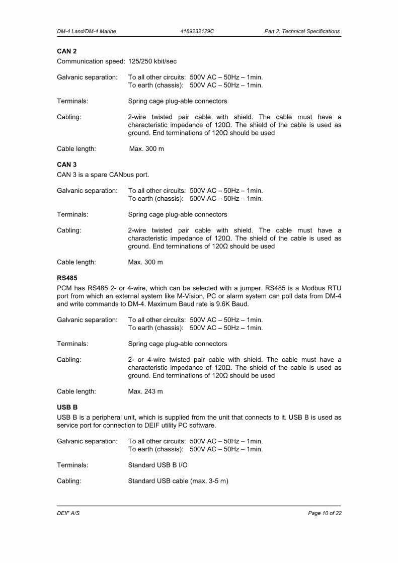
CAN 2 Communication speed: 125/250 kbit/sec Galvanic separation: To all other circuits: 500V AC – 50Hz – 1min. To earth (chassis): 500V AC – 50Hz – 1min. Terminals: Spring cage plug-able connectors Cabling: 2-wire twisted pair cable with shield. The cable must have a
characteristic impedance of 120Ω. The shield of the cable is used as ground. End terminations of 120Ω should be used
Cable length: Max. 300 m
CAN 3 CAN 3 is a spare CANbus port. Galvanic separation: To all other circuits: 500V AC – 50Hz – 1min. To earth (chassis): 500V AC – 50Hz – 1min. Terminals: Spring cage plug-able connectors Cabling: 2-wire twisted pair cable with shield. The cable must have a
characteristic impedance of 120Ω. The shield of the cable is used as ground. End terminations of 120Ω should be used
Cable length: Max. 300 m
RS485 PCM has RS485 2- or 4-wire, which can be selected with a jumper. RS485 is a Modbus RTU port from which an external system like M-Vision, PC or alarm system can poll data from DM-4 and write commands to DM-4. Maximum Baud rate is 9.6K Baud. Galvanic separation: To all other circuits: 500V AC – 50Hz – 1min. To earth (chassis): 500V AC – 50Hz – 1min. Terminals: Spring cage plug-able connectors Cabling: 2- or 4-wire twisted pair cable with shield. The cable must have a
characteristic impedance of 120Ω. The shield of the cable is used as ground. End terminations of 120Ω should be used
Cable length: Max. 243 m
USB B USB B is a peripheral unit, which is supplied from the unit that connects to it. USB B is used as service port for connection to DEIF utility PC software. Galvanic separation: To all other circuits: 500V AC – 50Hz – 1min. To earth (chassis): 500V AC – 50Hz – 1min. Terminals: Standard USB B I/O Cabling: Standard USB cable (max. 3-5 m)
DM-4 Land/DM-4 Marine 4189232129C Part 2: Technical Specifications
DEIF A/S Page 11 of 22
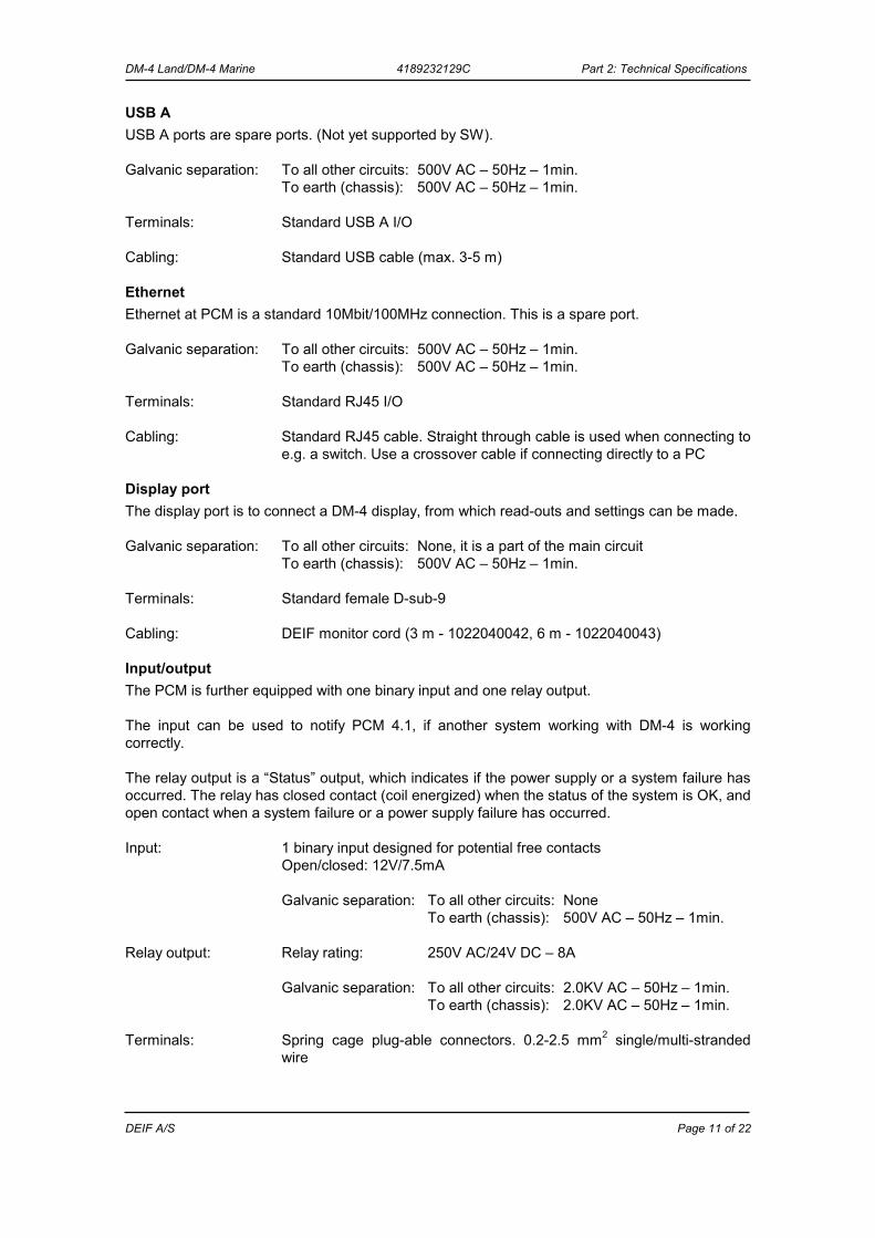
USB A USB A ports are spare ports. (Not yet supported by SW). Galvanic separation: To all other circuits: 500V AC – 50Hz – 1min. To earth (chassis): 500V AC – 50Hz – 1min. Terminals: Standard USB A I/O Cabling: Standard USB cable (max. 3-5 m)
Ethernet Ethernet at PCM is a standard 10Mbit/100MHz connection. This is a spare port. Galvanic separation: To all other circuits: 500V AC – 50Hz – 1min. To earth (chassis): 500V AC – 50Hz – 1min. Terminals: Standard RJ45 I/O Cabling: Standard RJ45 cable. Straight through cable is used when connecting to
e.g. a switch. Use a crossover cable if connecting directly to a PC
Display port The display port is to connect a DM-4 display, from which read-outs and settings can be made. Galvanic separation: To all other circuits: None, it is a part of the main circuit To earth (chassis): 500V AC – 50Hz – 1min. Terminals: Standard female D-sub-9 Cabling: DEIF monitor cord (3 m - 1022040042, 6 m - 1022040043)
Input/output The PCM is further equipped with one binary input and one relay output. The input can be used to notify PCM 4.1, if another system working with DM-4 is working correctly. The relay output is a “Status” output, which indicates if the power supply or a system failure has occurred. The relay has closed contact (coil energized) when the status of the system is OK, and open contact when a system failure or a power supply failure has occurred. Input: 1 binary input designed for potential free contacts Open/closed: 12V/7.5mA Galvanic separation: To all other circuits: None To earth (chassis): 500V AC – 50Hz – 1min. Relay output: Relay rating: 250V AC/24V DC – 8A Galvanic separation: To all other circuits: 2.0KV AC – 50Hz – 1min. To earth (chassis): 2.0KV AC – 50Hz – 1min. Terminals: Spring cage plug-able connectors. 0.2-2.5 mm2 single/multi-stranded
wire
DM-4 Land/DM-4 Marine 4189232129C Part 2: Technical Specifications
DEIF A/S Page 12 of 22
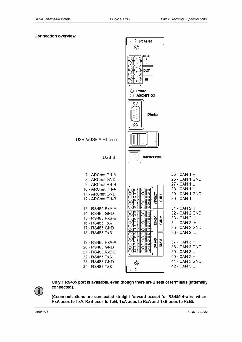
Connection overview
25 - CAN 1 H 26 - CAN 1 GND 27 - CAN 1 L 28 - CAN 1 H 29 - CAN 1 GND 30 - CAN 1 L 31 - CAN 2 H 32 - CAN 2 GND 33 - CAN 2 L 34 - CAN 2 H 35 - CAN 2 GND 36 - CAN 2 L 37 - CAN 3 H 38 - CAN 3 GND 39 - CAN 3 L 40 - CAN 3 H 41 - CAN 3 GND 42 - CAN 3 L
7 - ARCnet PH-A 8 - ARCnet GND 9 - ARCnet PH-B 10 - ARCnet PH-A 11 - ARCnet GND 12 - ARCnet PH-B 13 - RS485 RxA-A 14 - RS485 GND 15 - RS485 RxB-B 16 - RS485 TxA 17 - RS485 GND 18 - RS485 TxB 19 - RS485 RxA-A 20 - RS485 GND 21 - RS485 RxB-B 22 - RS485 TxA 23 - RS485 GND 24 - RS485 TxB
USB B
USB A/USB A/Ethernet
Only 1 RS485 port is available, even though there are 2 sets of terminals (internally connected). (Communications are connected straight forward except for RS485 4-wire, where RxA goes to TxA, RxB goes to TxB, TxA goes to RxA and TxB goes to RxB).
DM-4 Land/DM-4 Marine 4189232129C Part 2: Technical Specifications
DEIF A/S Page 13 of 22
Input Output Module 4.1 (IOM 4.1) Dimension: Width 30.5 mm (6 TE) Supply: From PCM module via the backplane Power consumption: Typical: 2W Max.: 6W Temperature: Reference: +15…+30°C Nominal: -10…+55°C Operational: -25…+70°C Storage: -40…+70°C Climate: Class HSE (to DIN 40040) Safety: To EN 61010-1, installation category (overvoltage category) III, 600V,
pollution degree 2 Protection: IP20 (to IEC 529 and EN 60529) EMC/CE: To EN 61000-6-1/2/3/4, SS4631503 (PL4) and IEC 255-3 Material: All plastic materials are self-extinguishing according to UL94 (V1)
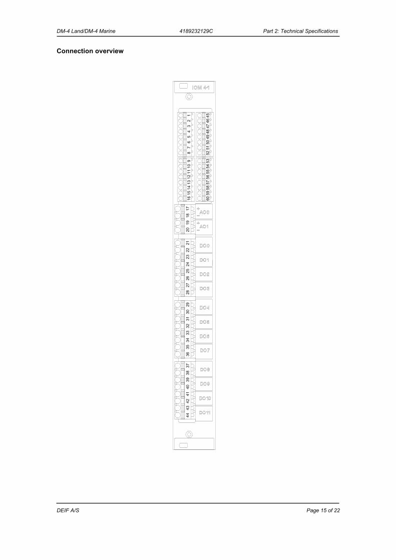
16 input channels The IOM 4.1 contains 16 input channels, which may be individually configured as a current input (0...20mA), a voltage input (0…10V) or as a binary input (CC/OC). Live zero (offset) of the analogue inputs (e.g. 2…10V or 4…20mA) is available through the application programme. The input channel configuration (analogue/binary) must correspond to the input definitions in the application programme (in the PCM). The status of the binary input is detected by an active voltage level detector circuit in the IOM 4.1, which may be connected to a potential free contact only. All “COM” terminals are in all three configurations connected to the internal ground. Cable supervision is optional for channels configured as binary input. Measurement: Accuracy: Class 1 (to IEC 688) Resolution: 10bit (0.1% of full scale) Impedance: mA - input: 50Ω V - input: 15KΩ Binary input: Max. resistance for ON detection: 100Ω Resistance for cable supervision: 270Ω +/-10% Galvanic separation: No galvanic separation to internal ground Between inputs and earth (chassis): 500V AC – 50Hz – 1 min. Terminals: Spring cage plug-able connectors. 0.14-1.5 mm2 single/multi-stranded
wire
DM-4 Land/DM-4 Marine 4189232129C Part 2: Technical Specifications
DEIF A/S Page 14 of 22
12 relay output channels The IOM 4.1 contains 12 relay outputs with programmable active position. The active position may be a Closed Contact (CC) or an Open Contact (OC), dependent on the output channel setup in the application programme (in the PCM). The relay position is a Closed Contact with an energized coil. All relay outputs are potential free contacts, and each output is galvanically insulated from the DELOMATIC system. If a power supply or system failure appears, all relay outputs are set to an Open Contact position (OC). Contact ratings: Max.: 250V AC/24V DC, 8A Galvanic separation: Between relay contacts and other circuits: 2.0KV AC – 50Hz – 1min. Between different relay contacts: 2.0KV AC – 50Hz – 1min. Between relay contacts and earth (chassis): 2.0KV AC – 50Hz – 1min. Terminals: Spring cage plug-able connectors. 0.2-2.5 mm2 single/multi-stranded wire
2 analogue output channels The IOM 4.1 contains 2 analogue outputs (0...20mA), both galvanically separated. Live zero (offset) of the analogue outputs (e.g. 4...20mA) is available through the application programme (in the PCM). If a power supply or system failure appears, both analogue output channels are set to zero output (0mA). Output: 0…20mA Load: Max. 500Ω Accuracy: Class 0.5 (to IEC 688) Resolution: 10bit (0.1% of full scale) Galvanic separation: Between analogue outputs and other circuits: 500V AC – 50Hz – 1min. Between two analogue outputs: 500V AC – 50Hz – 1min. Between analogue outputs and earth (chassis): 500V AC – 50Hz – 1min. Terminals: Spring cage plug-able connectors. 0.2-2.5 mm2 single/multi-stranded wire
DM-4 Land/DM-4 Marine 4189232129C Part 2: Technical Specifications
DEIF A/S Page 15 of 22
4442
4038
4341
3937
3634
3230
3533
3129
2826
2422
2725
2321
1719
1820
109
1211
1314 58
5755
5653
5459
601615
78 52
5146
4548
4749
5065
34
12
Connection overview

DM-4 Land/DM-4 Marine 4189232129C Part 2: Technical Specifications
DEIF A/S Page 16 of 22
Synchronising Module 4.1 (SCM 4.1) Dimension: Width 30.5 mm (6 TE) (SCM 4·1) Supply: From PCM module via the backplane Power consumption: Typical: 2W Max.: 3W Temperature: Reference: +15…+30°C Nominal: -10…+55°C Operational: -25…+70°C Storage: -40…+70°C Climate: Class HSE (to DIN 40040) Safety: To EN 61010-1, installation category (overvoltage category) III, 600V,
pollution degree 2 Protection: IP20 (to IEC 529 and EN 60529) EMC/CE: To EN 61000-6-1/2/3/4, SS4631503 (PL4) and IEC 255-3 Material: All plastic materials are self-extinguishing according to UL94 (V1)
3-phase multi-transducer The SCM 4·1 has one 3-phase current input and two 3-phase voltage inputs. From these inputs all relevant values are measured and calculated. Measurement: True RMS Accuracy: Class 0.5 (to IEC 688) Frequency: 30…70Hz Harmonics: Max. 500Hz are measured and included in the results
and calculations Voltage: Range: 100…690V AC +/-20% (phase-phase) Dynamic area: 0…135% (sine wave) Load: Max. 0.25VA/phase (1MΩ/phase) Galvanic separation: To all other circuits: 3250V AC – 50Hz – 1min. To earth (chassis): 3250V AC – 50Hz – 1min. Terminals: Spring cage plug-able connectors. 0.2-2.5 mm2 single/multi-stranded
wire Current: Range: -/1A or -/5A AC Dynamic area: 0…400% (sine wave) Load: Max. 0.25VA/phase Max. overcurrent: 4 x In continuously 20 x In, 10 sec. (max. 75A) 80 x In, 1 sec. (max. 300A)
DM-4 Land/DM-4 Marine 4189232129C Part 2: Technical Specifications
DEIF A/S Page 17 of 22
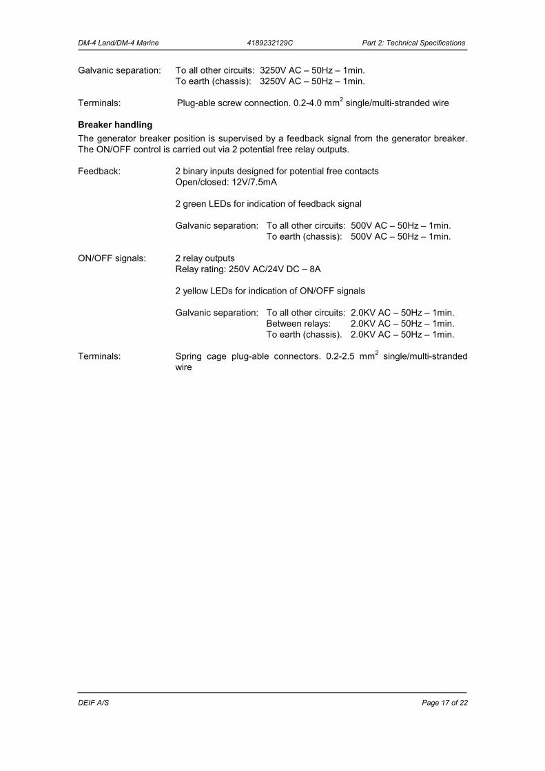
Galvanic separation: To all other circuits: 3250V AC – 50Hz – 1min. To earth (chassis): 3250V AC – 50Hz – 1min. Terminals: Plug-able screw connection. 0.2-4.0 mm2 single/multi-stranded wire
Breaker handling The generator breaker position is supervised by a feedback signal from the generator breaker. The ON/OFF control is carried out via 2 potential free relay outputs. Feedback: 2 binary inputs designed for potential free contacts Open/closed: 12V/7.5mA 2 green LEDs for indication of feedback signal Galvanic separation: To all other circuits: 500V AC – 50Hz – 1min. To earth (chassis): 500V AC – 50Hz – 1min. ON/OFF signals: 2 relay outputs Relay rating: 250V AC/24V DC – 8A 2 yellow LEDs for indication of ON/OFF signals Galvanic separation: To all other circuits: 2.0KV AC – 50Hz – 1min. Between relays: 2.0KV AC – 50Hz – 1min. To earth (chassis). 2.0KV AC – 50Hz – 1min. Terminals: Spring cage plug-able connectors. 0.2-2.5 mm2 single/multi-stranded
wire
DM-4 Land/DM-4 Marine 4189232129C Part 2: Technical Specifications
DEIF A/S Page 18 of 22
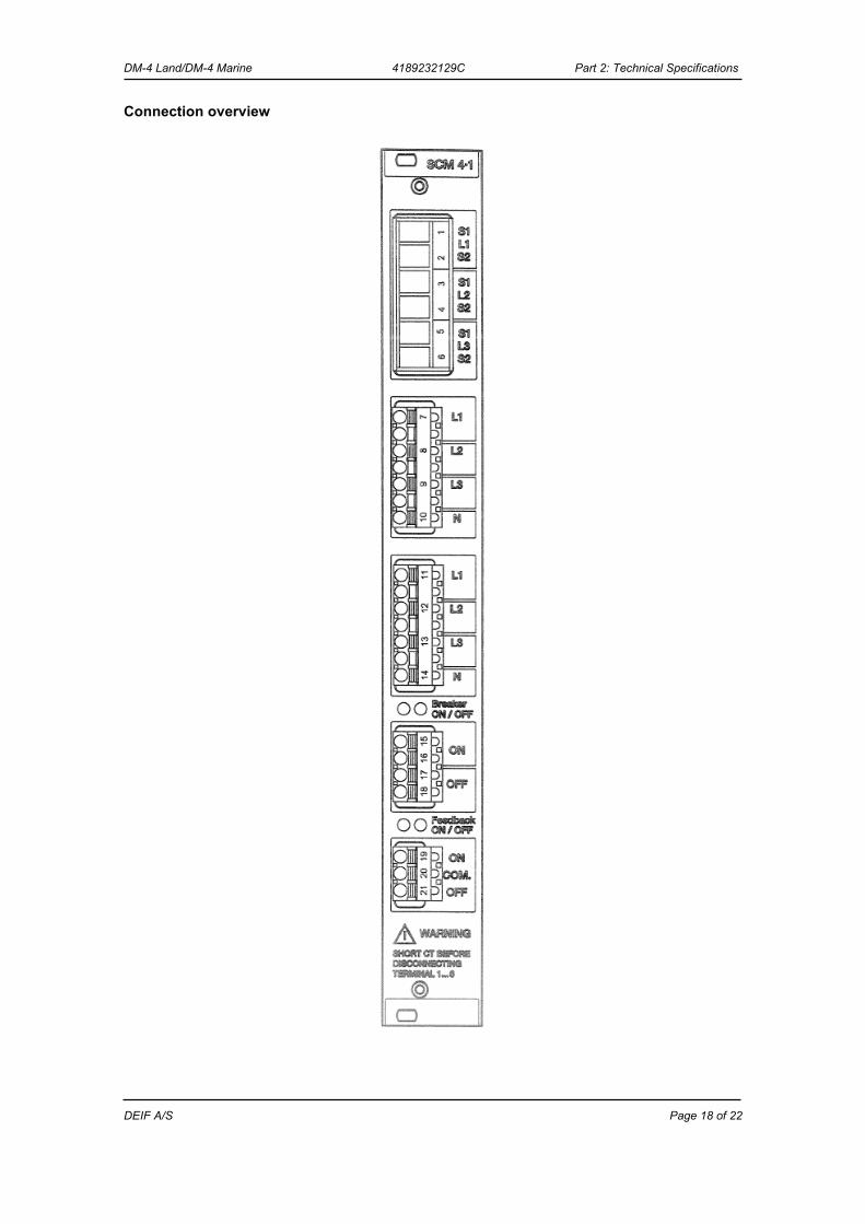
Connection overview
DM-4 Land/DM-4 Marine 4189232129C Part 2: Technical Specifications
DEIF A/S Page 19 of 22
Synchronising Module 4.2 (SCM 4.2)
Dimension: Width 60.96 mm (12TE) (SCM 4·2) Supply: From PCM module via the backplane Power consumption: Typical: 2W Max.: 3W Temperature: Reference: +15…+30°C Nominal: -10…+55°C Operational: -25…+70°C Storage: -40…+70°C Climate: Class HSE (to DIN 40040) Safety: To EN 61010-1, installation category (overvoltage category) III, 600V,
pollution degree 2 Protection: IP20 (to IEC 529 and EN 60529) EMC/CE: To EN 61000-6-1/2/3/4, SS4631503 (PL4) and IEC 255-3 Material: All plastic materials are self-extinguishing according to UL94 (V1)
3-phase multi-transducer The SCM 4·2 has one 3-phase current input and two 3-phase voltage inputs. From these inputs all relevant values are measured and calculated. Measurement: True RMS Accuracy: Class 0.5 (to IEC 688) Frequency: 30…70Hz Harmonics: Max. 500Hz are measured and included in the results
and calculations Voltage: Range: 100…690V AC +/-20% (phase-phase) Dynamic area: 0…140% (sine wave) Load: Max. 0.25VA/phase (1MΩ/phase) Galvanic separation: To all other circuits: 3250V AC – 50Hz – 1min. To earth (chassis): 3250V AC – 50Hz – 1min. Terminals: Spring cage plug-able connectors. 0.2-2.5 mm2 single/multi-stranded
wire Current: Range: -/1A or -/5A AC Dynamic area: 0…400% (sine wave) Load: Max. 0.25VA/phase Max. overcurrent: 4 x In continuously 20 x In, 10 sec. (max. 75A) 80 x In, 1 sec. (max. 300A)
DM-4 Land/DM-4 Marine 4189232129C Part 2: Technical Specifications
DEIF A/S Page 20 of 22
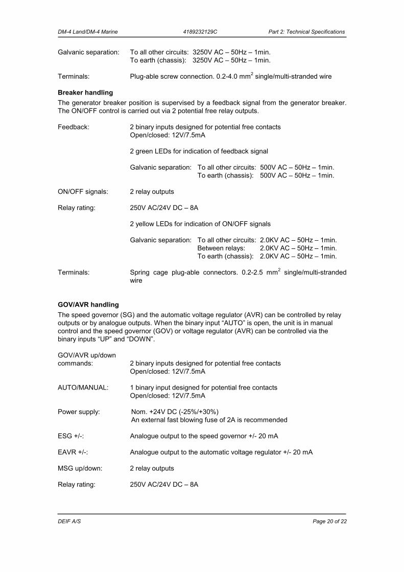
Galvanic separation: To all other circuits: 3250V AC – 50Hz – 1min. To earth (chassis): 3250V AC – 50Hz – 1min.
Terminals: Plug-able screw connection. 0.2-4.0 mm2 single/multi-stranded wire
Breaker handling The generator breaker position is supervised by a feedback signal from the generator breaker. The ON/OFF control is carried out via 2 potential free relay outputs. Feedback: 2 binary inputs designed for potential free contacts Open/closed: 12V/7.5mA 2 green LEDs for indication of feedback signal Galvanic separation: To all other circuits: 500V AC – 50Hz – 1min. To earth (chassis): 500V AC – 50Hz – 1min. ON/OFF signals: 2 relay outputs Relay rating: 250V AC/24V DC – 8A 2 yellow LEDs for indication of ON/OFF signals Galvanic separation: To all other circuits: 2.0KV AC – 50Hz – 1min. Between relays: 2.0KV AC – 50Hz – 1min. To earth (chassis): 2.0KV AC – 50Hz – 1min. Terminals: Spring cage plug-able connectors. 0.2-2.5 mm2 single/multi-stranded
wire
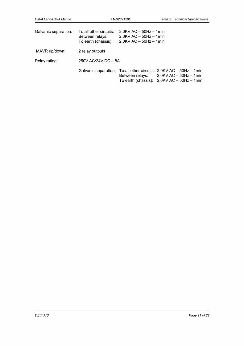
GOV/AVR handling The speed governor (SG) and the automatic voltage regulator (AVR) can be controlled by relay outputs or by analogue outputs. When the binary input “AUTO” is open, the unit is in manual control and the speed governor (GOV) or voltage regulator (AVR) can be controlled via the binary inputs “UP” and “DOWN”. GOV/AVR up/down commands: 2 binary inputs designed for potential free contacts Open/closed: 12V/7.5mA AUTO/MANUAL: 1 binary input designed for potential free contacts Open/closed: 12V/7.5mA Power supply: Nom. +24V DC (-25%/+30%) An external fast blowing fuse of 2A is recommended ESG +/-: Analogue output to the speed governor +/- 20 mA EAVR +/-: Analogue output to the automatic voltage regulator +/- 20 mA MSG up/down: 2 relay outputs Relay rating: 250V AC/24V DC – 8A
DM-4 Land/DM-4 Marine 4189232129C Part 2: Technical Specifications
DEIF A/S Page 21 of 22
Galvanic separation: To all other circuits: 2.0KV AC – 50Hz – 1min. Between relays: 2.0KV AC – 50Hz – 1min. To earth (chassis): 2.0KV AC – 50Hz – 1min. MAVR up/down: 2 relay outputs Relay rating: 250V AC/24V DC – 8A Galvanic separation: To all other circuits: 2.0KV AC – 50Hz – 1min. Between relays: 2.0KV AC – 50Hz – 1min. To earth (chassis): 2.0KV AC – 50Hz – 1min.
DM-4 Land/DM-4 Marine 4189232129C Part 2: Technical Specifications
DEIF A/S Page 22 of 22
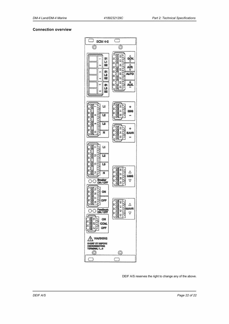
Connection overview
DEIF A/S reserves the right to change any of the above.