dELAb GPS Module
62
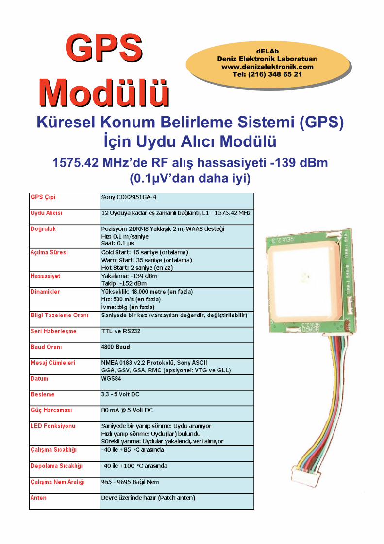
dELAb Deniz Elektronik Laboratuarı www.denizelektronik.com Tel: (216) 348 65 21 GPS Modülü GPS Modülü Küresel Konum Belirleme Sistemi (GPS) İçin Uydu Alıcı Modülü 1575.42 MHz’de RF alış hassasiyeti -139 dBm (0.1μV’dan daha iyi)
Transcript of dELAb GPS Module
dELAbDeniz Elektronik Laboratuarıwww.denizelektronik.com
Tel: (216) 348 65 21
GPS Modülü
GPS ModülüKüresel Konum Belirleme Sistemi (GPS)
İçin Uydu Alıcı Modülü1575.42 MHz’de RF alış hassasiyeti -139 dBm
(0.1μV’dan daha iyi)
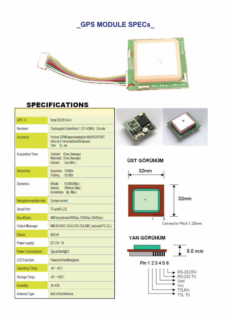
_GPS MODULE SPECs__GPS MODULE SPECs_
Hafıza Pili (Şarjlı)
Besleme ve Haberleşme Portu
RF Alıcı
Dahili GPS Patch Anten
Sony CXD2951GA-4GPS Çipi
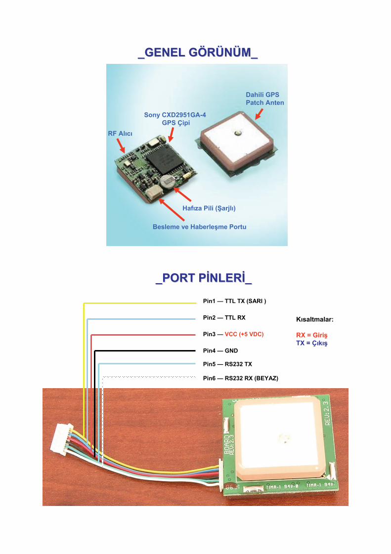
Pin1 — TTL TX (SARI )
Pin2 — TTL RX
Pin3 — VCC (+5 VDC)
Pin4 — GND
Pin5 — RS232 TX
Pin6 — RS232 RX (BEYAZ)
Kısaltmalar:
RX = GirişTX = Çıkış
_GENEL G_GENEL GÖÖRRÜÜNNÜÜM_M_
_PORT P_PORT PİİNLERNLERİİ__
GPS Nedir ?
GPS; çok hassas yörüngeleri olan, her biri bu yörüngesini günde iki kez turlayan, dünyamızı bir ağ gibi saran 30 adet uydunun (uydu sayıları artmaktadır, yedek uydular da devreye girmektedir) yaydığı sinyaller vasıtasıyla bulunulan konumun belirlenmesine yarayan bir sistemdir. Burada tanıtımı yapılan modül, ticari GPS cihazlarının kalbi ve beynidir.GPS projesi askeri amaçlı olarak başlamış ancak 1980 yılından itibaren sivil kullanıma da açılmıştır. GPS, dünyanın her yerinde, her türlü hava şartında ve 24 saat kesintisiz çalışmaktadır. Kullanımı için herhangi bir ücret gerektirmez.
GPS UYDULARININ ÇALIŞMA PRENSİPLERİ
GPS uyduları çok hassas yörüngelere sahiptirler ve bu yörüngeyi günde iki kez turlamaktadırlar. GPS uyduları bilgileri bu yörüngelerden dünyamıza iletirler. GPS alıcıları bu bilgiler ışığında en az üç uydu sinyalini yakalayarak bir üçgen oluştururlar ve bundan yola çıkarak da dünya üzerinde bulunulan konumu kesin olarak saptarlar. Kesinlik açısından en az 3 uydu sinyalinin yakalanması gerekir. Daha fazla uydu sinyali yakalanırsa (GPS modülü aynı anda 12 uydu sinyali yakalayabilmektedir) deniz seviyesinden yüksekliğiniz de hesaplanabilir. GPS uyduları L1 ve L2 olarak adlandırılan iki adet düşük güçlü sinyal yayınlarlar. Sivil kullanımda 1575.42 MHz frekansındaki L1 kullanılır. Bu sinyaller bulut, cam ve plastikten geçebilir ancak çok daha yoğun ortamlardan geçemezler.GPS modülü, uydu sinyallerini yakalayarak (en az 3 uydu) bu sinyalleri alarak kendi bulunduğu konumu hesaplamakta ve NMEA 0183 adı verilen protokolde ASCII olarak 4800 baud hızında TTL ve RS232 'den seri olarak vermektedir.Bu protokol yazılımla çözülerek;
- Bulunduğunuz konum (Enlem/Boylam)- Bulunduğunuz yerin deniz seviyesinden yüksekliği- Anlık hızınız (hareket ediyorsanız)- Gerçek saat ve tarih (UTC olarak)- Elektronik pusula (izlenen nesnenin hangi yöne doğru gittiği saptanabilir)
gibi verilere ulaşılır. NMEA 0183 protokol çıktısına örnek verirsek:
$GPGGA,222300,4000.0000,N,29000.0000,E,1,05,2.4,30.5,M,-33.3,M,,*57$GPRMC,222300,A,4000.0000,N,29000.0000,E,10.0,245.0,091106,9.5,W,A*36
Bu kod çözüldüğünde;
- Pozisyon: 40.00.00 Kuzey, 29.00.00 Doğu- Hız : 10 MPH- Rakım: 100 Feet- Yön : 245 Derece- Saat 22:23:00 UTC (Atom saati)- Tarih: 09.11.2006
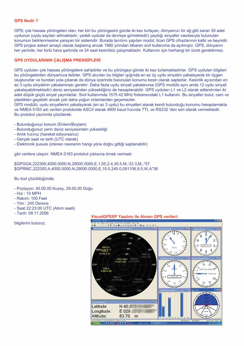
bilgilerini buluruz.VisualGPSXP Yazılımı ile Alınan GPS verileri:
• Modülün çalışması için 5V besleme verilmesi yeterlidir.Çıkışı direkt bilgisayara bağlanarak (RS232 portu ile) NMEA uyumlu çeşitli yazılımlarlaGPS verileri okunabilir.
• NMEA protokolü formatı ASCII olduğundan çözmesi binary sistemlere göre çok kolaydır. Hem bilgisayar hem de mikrodenetleyici projeleriyle uygulama hazırlamak kolaydır.
• Üzerinde bulunan anten hem kullanım kolaylığı sağlar hem de harici antenli sistemlere göredaha ekonomiktir.
• Alıcı mutlak surette sıvı yalıtımlı plastik bir malzeme içine konularak kullanılmalıdır.
• Cihaz çalışırken üzerinde bulunan kırmızı led işıldamaya başlar:Saniyede bir yanıp sönme: Uydu(lar) aranıyorHızlı yanıp sönme: Uydu(lar) bulundu, yakalanıyorSürekli ışıldama: Uydulara (en az 3 adet) kilitlendi, veri alınıyor anlamına gelmektedir.
• Araç veya diğer hareketli sisitemlerin izlenmesi için cihaz kapalı mekanlardaolmamalıdır. Ev içi kullanımında sinyaller zayıflayacaktır. Birkaç uyduyu yakalaması içinmodülün en az cam kenarı ve en iyisi balkon veya açık alanda olması gerekir.
• Modülün üzerindeki anten, en iyi yere paralel konumda veri almak üzere tasarlanmıştır.Mümkün olduğunca bu şekilde sabitlenmesi önerilir.
• Tarih ve Saat bilgileri için en az bir uydunun yakalanması yeterlidir. Bu bilgiler yakalananilk uydudan alınıp modüldeki gerçek zaman saati (RTC) güncellenir. Bundan sonrauydu bağlantısı kopsa dahi modüldeki şarj edilebilir yedekleme pili sayesinde tarih ve saatbilgileri bir dahaki bağlantıya kadar sürekli güncel kalacaktır.
• Modüldeki hafıza pili besleme bağlı iken otomatik olarak şarj olur. Bu pilin görevi en sonokunan uydu verilerinin, kullanıcı seçeneklerinin ve gerçek zaman saatinin beslemekesildiğinde de saklanabilmesini sağlamaktır. Modülün çalışması pile bağlı değildir!
• GPS Modülü, uydulardan 1 µs hata payıyla atom saati verilerini aldığından, saat uygulamalarında da kullanılabilir. Atom saati en doğru saat verisidir.
• Kullanım alanları: Hertürlü hareketli kara, hava ve deniz araçlarının izlenmesi. Haritacılık, petrol araştırmaları,sınırların belirlenmesi ve diğer arazi çalışmaları, hobiciler için çeşitli uygulamalar, model uçakların pusula, hız ve yükseklik tesbitleri vs için, küçük balıkçı tekneleri, dağcılar için yerbelirleme ve sisli havalarda yön bulma, dış mekan saat uygulamaları vs gibi projelerdekullanılabilir.
_UYGULAMA NOTLARI__UYGULAMA NOTLARI_

Proje GeliProje Gelişştiricileri tiricileri İİççin; in;
Sony CXD2951GASony CXD2951GA--44Kontrol ProtokolKontrol Protokolüü
@CLR@CLRkomutu ile fabrika ayarlarkomutu ile fabrika ayarlarıına na
ddöönnüülebilmektedir.lebilmektedir.
CXD2951 Communication Command Specifications
1
CXD2951
Communication Command Specifications
Ver. 1.8
Copyright © 2003,2004 Sony Corporation
Modifying and distributing this specification without permission is prohibited. Sony does not take any responsibility for modified contents.
CXD2951 Communication Command Specifications
2
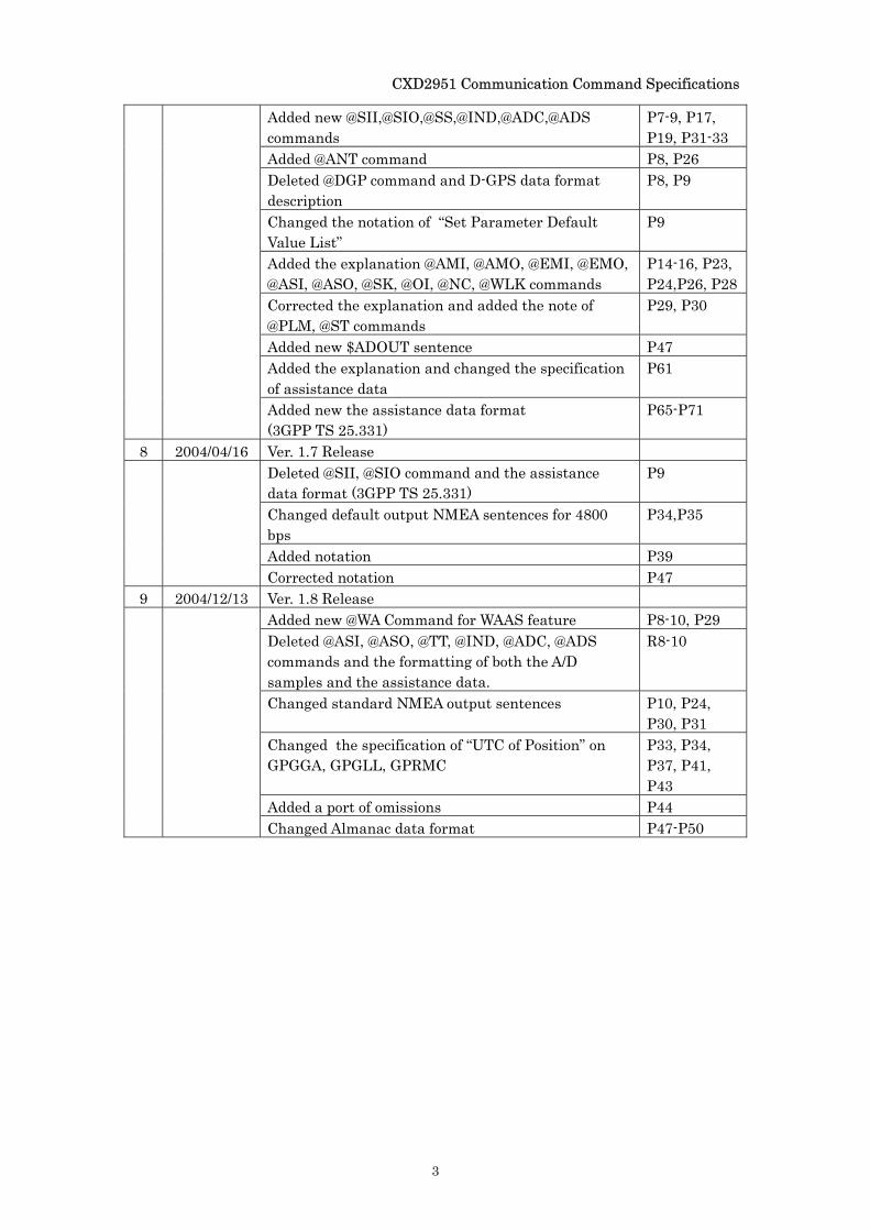
Revision Record
No. Date Contents Change page 1 2003/09/23 Ver. 1.0 Release 2 2003/09/23 Ver. 1.1 Release
Added the revision record P2 Corrected “@PH” command name in the command list P7 Corrected the order in the command list P7 Corrected the explanations for “Speed over ground” in GPRMC, GPVTG sentence
P40,P41
3 2003/12/05 Ver. 1.2 Release Added baud rate 19200/38400bps P3 Deleted @AL, @EP, @HL, @CRD, @CB, @TZ, @GS, @GSV command
P7
Changed the variable format of @PM command P11 Changed the specification of @TT, @SK, @OI, @PV, @NC, @ANT command
P8,P12,P20-P23,P25
Added new command @WLK, @PLM, @ST P7,P26-P28 Added new NMEA sentence SONY original PSGSA P29,P38,P42 Added the descriptions of the specifications for “Longitude” in GPGGA, GPGLL, GPRMC sentence
P30-P32,P35
Changed the specifications for “UTC of position” in GPGGA, GPGLL, GPRMC sentence
P30-P32,P35
Changed the notation of the timing figure P43 Changed the specification of almanac/ephemeris data format
P45-P48,P50-P52
Changed the data format of Assistance data P56-P58 4 2003/12/05 Ver. 1.3 Release
Corrected the example of the response to commands P5 Deleted @ANT in the Set Parameter Default Value List
P8
Added the specification of output NEMA sentences at 4800 bps
P29
5 2004/01/08 Ver. 1.4 Release Added the limit of command length P4 Changed the setting upper limit of @TM command P10 Added the note of @TT command P12 Added the notice P29 Corrected the note for “SNR” on GPGSV sentence P35
Added the note for “Speed over ground” on GPRMC, GPVTG sentence
P36,P37
6 2004/01/08 Ver. 1.5 Release Deleted @ANT command P7 Corrected the example of GPRMC sentence P35
7 2004/04/16 Ver. 1.6 Release Changed explanations notation P5 Changed the reported format of @PV command P6, P25
CXD2951 Communication Command Specifications
3
Added new @SII,@SIO,@SS,@IND,@ADC,@ADS commands
P7-9, P17, P19, P31-33
Added @ANT command P8, P26 Deleted @DGP command and D-GPS data format description
P8, P9
Changed the notation of “Set Parameter Default Value List”
P9
Added the explanation @AMI, @AMO, @EMI, @EMO, @ASI, @ASO, @SK, @OI, @NC, @WLK commands
P14-16, P23, P24,P26, P28
Corrected the explanation and added the note of @PLM, @ST commands
P29, P30
Added new $ADOUT sentence P47 Added the explanation and changed the specification of assistance data
P61
Added new the assistance data format (3GPP TS 25.331)
P65-P71
8 2004/04/16 Ver. 1.7 Release Deleted @SII, @SIO command and the assistance data format (3GPP TS 25.331)
P9
Changed default output NMEA sentences for 4800 bps
P34,P35
Added notation P39
Corrected notation P47 9 2004/12/13 Ver. 1.8 Release
Added new @WA Command for WAAS feature P8-10, P29 Deleted @ASI, @ASO, @TT, @IND, @ADC, @ADS commands and the formatting of both the A/D samples and the assistance data.
R8-10
Changed standard NMEA output sentences P10, P24, P30, P31
Changed the specification of “UTC of Position” on GPGGA, GPGLL, GPRMC
P33, P34, P37, P41, P43
Added a port of omissions P44
Changed Almanac data format P47-P50
CXD2951 Communication Command Specifications
4
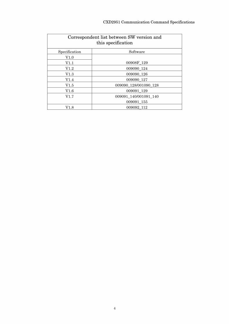
Correspondent list between SW version and
this specification
Specification Software V1.0 V1.1
00908F_129
V1.2 009090_124 V1.3 009090_126 V1.4 009090_127 V1.5 009090_128/001090_128 V1.6 009091_129 V1.7 009091_140/001091_140
009091_155 V1.8 009092_112
CXD2951 Communication Command Specifications
i
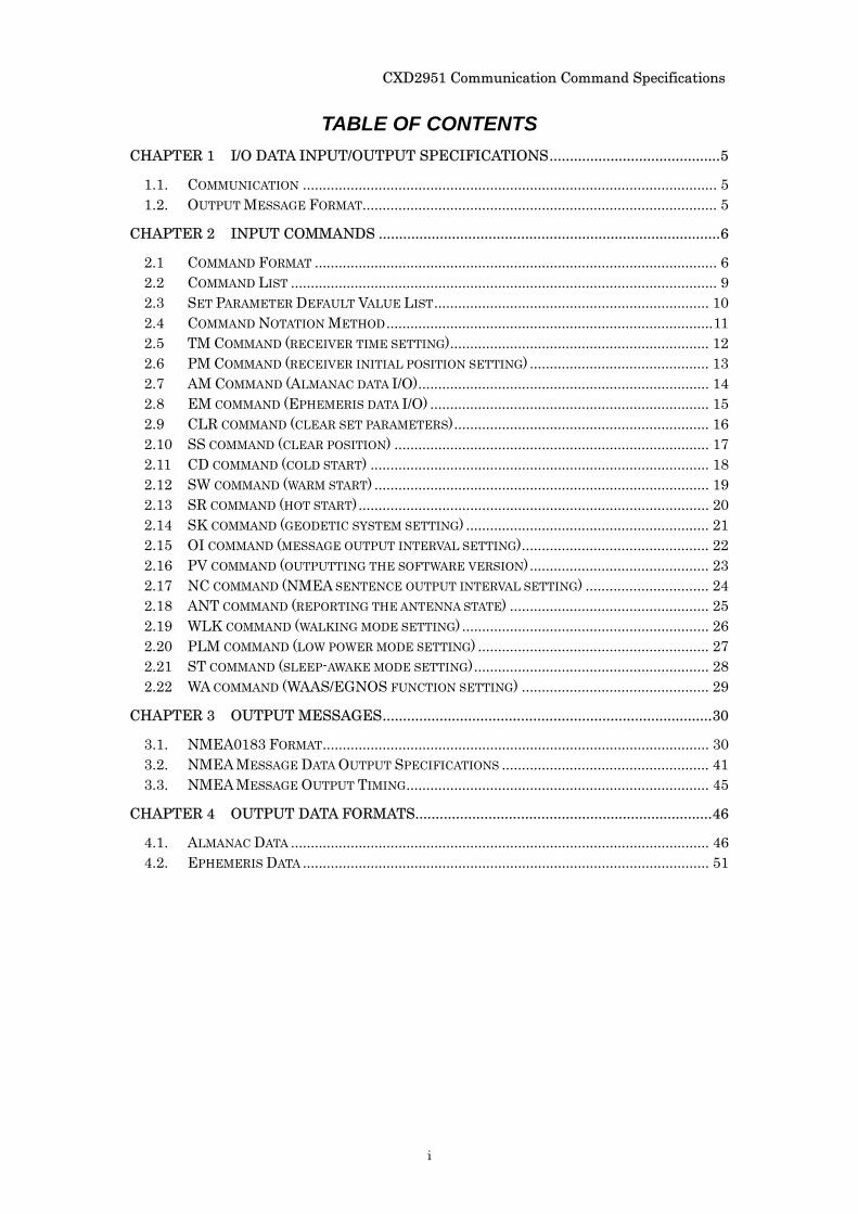
TABLE OF CONTENTS
CHAPTER 1 I/O DATA INPUT/OUTPUT SPECIFICATIONS..........................................5
1.1. COMMUNICATION ........................................................................................................ 5 1.2. OUTPUT MESSAGE FORMAT......................................................................................... 5
CHAPTER 2 INPUT COMMANDS ....................................................................................6
2.1 COMMAND FORMAT ..................................................................................................... 6 2.2 COMMAND LIST ........................................................................................................... 9 2.3 SET PARAMETER DEFAULT VALUE LIST..................................................................... 10 2.4 COMMAND NOTATION METHOD..................................................................................11 2.5 TM COMMAND (RECEIVER TIME SETTING)................................................................. 12 2.6 PM COMMAND (RECEIVER INITIAL POSITION SETTING) ............................................. 13 2.7 AM COMMAND (ALMANAC DATA I/O)......................................................................... 14 2.8 EM COMMAND (EPHEMERIS DATA I/O) ...................................................................... 15 2.9 CLR COMMAND (CLEAR SET PARAMETERS)................................................................ 16 2.10 SS COMMAND (CLEAR POSITION) ............................................................................... 17 2.11 CD COMMAND (COLD START) ..................................................................................... 18 2.12 SW COMMAND (WARM START) .................................................................................... 19 2.13 SR COMMAND (HOT START)........................................................................................ 20 2.14 SK COMMAND (GEODETIC SYSTEM SETTING) ............................................................. 21 2.15 OI COMMAND (MESSAGE OUTPUT INTERVAL SETTING)............................................... 22 2.16 PV COMMAND (OUTPUTTING THE SOFTWARE VERSION)............................................. 23 2.17 NC COMMAND (NMEA SENTENCE OUTPUT INTERVAL SETTING) ............................... 24 2.18 ANT COMMAND (REPORTING THE ANTENNA STATE) .................................................. 25 2.19 WLK COMMAND (WALKING MODE SETTING) .............................................................. 26 2.20 PLM COMMAND (LOW POWER MODE SETTING) .......................................................... 27 2.21 ST COMMAND (SLEEP-AWAKE MODE SETTING)........................................................... 28 2.22 WA COMMAND (WAAS/EGNOS FUNCTION SETTING) ............................................... 29
CHAPTER 3 OUTPUT MESSAGES.................................................................................30
3.1. NMEA0183 FORMAT................................................................................................. 30 3.2. NMEA MESSAGE DATA OUTPUT SPECIFICATIONS .................................................... 41 3.3. NMEA MESSAGE OUTPUT TIMING............................................................................ 45
CHAPTER 4 OUTPUT DATA FORMATS.........................................................................46
4.1. ALMANAC DATA ......................................................................................................... 46 4.2. EPHEMERIS DATA ...................................................................................................... 51
CXD2951 Communication Command Specifications
5
Chapter 1 I/O Data Input/Output Specifications
This chapter explains I/O specifications for CXD2951.
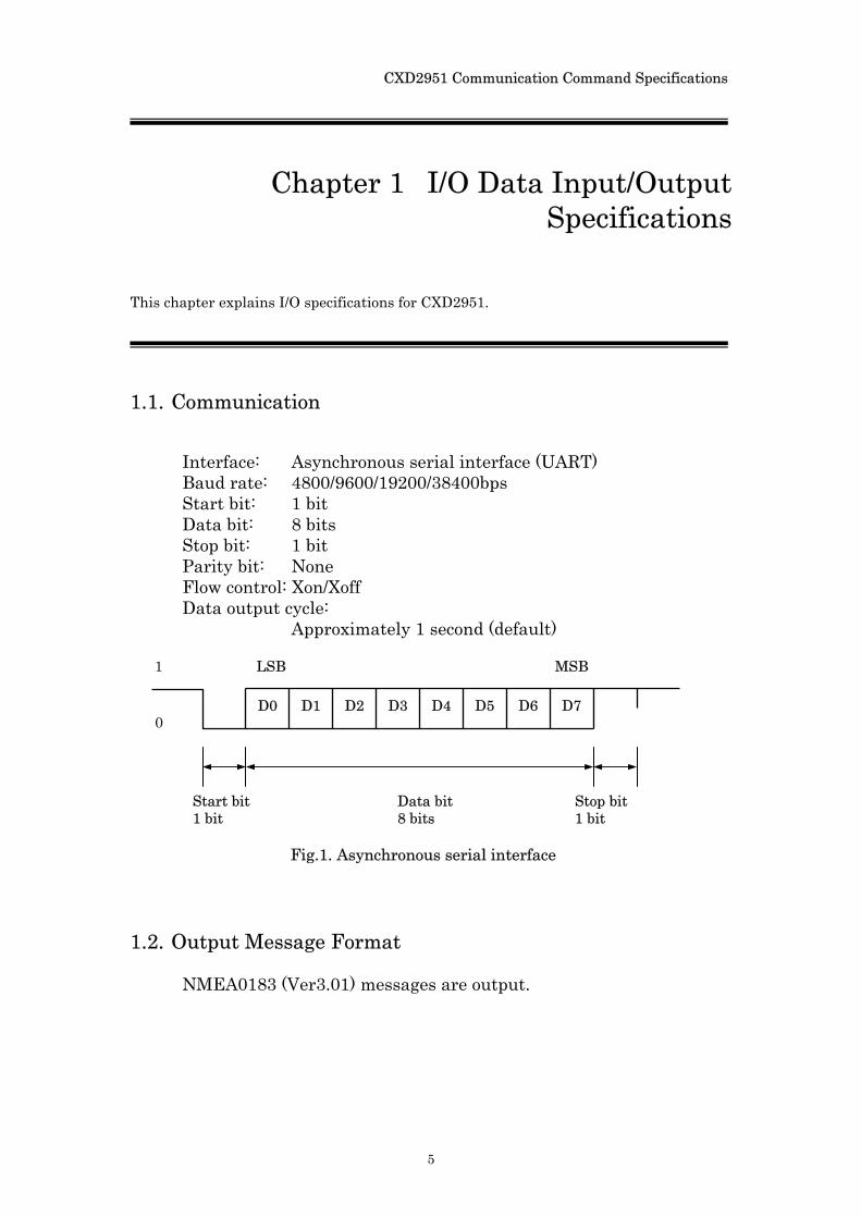
1.1. Communication
Interface: Asynchronous serial interface (UART) Baud rate: 4800/9600/19200/38400bps Start bit: 1 bit Data bit: 8 bits Stop bit: 1 bit Parity bit: None Flow control: Xon/Xoff Data output cycle:
Approximately 1 second (default)
1.2. Output Message Format
NMEA0183 (Ver3.01) messages are output.
1
0 D0 D1 D2 D3 D4 D5 D6 D7
Start bit 1 bit
Data bit 8 bits
Stop bit 1 bit
LSB MSB
Fig.1. Asynchronous serial interface
CXD2951 Communication Command Specifications
6
Chapter 2 Input Commands This chapter explains the input commands used in communication with the CXD2951.
2.1 Command Format
The communication command format consists of “@”symbol, a command and command parameters in that order. Command input is recognized after a CR (carriage return) and a LF (line feed) are received. When an input is successfully recognized, an echo is sent back. Then if the command name and specified parameter values are entered correctly, the command is processed accordingly. However if a command or characters other than those noted in this specification is used, that operation cannot be guaranteed. Command length has a maximum limit of 127 characters (from @ symbol to line feed). If there are over 128 characters including line feed, the operation cannot be guaranteed.
When the command is processed properly, a processing message
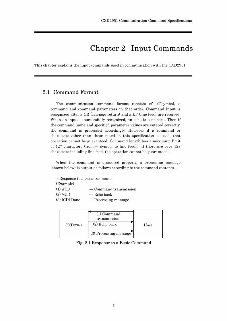
(shown below) is output as follows according to the command contents. • Response to a basic command (Example) (1) @CD ← Command transmission (2) @CD ← Echo back (3) [CD] Done ← Processing message
Host
CXD2951
(1) Command transmission
(2) Echo back
(3) Processing message
Fig. 2.1 Response to a Basic Command
CXD2951 Communication Command Specifications
7
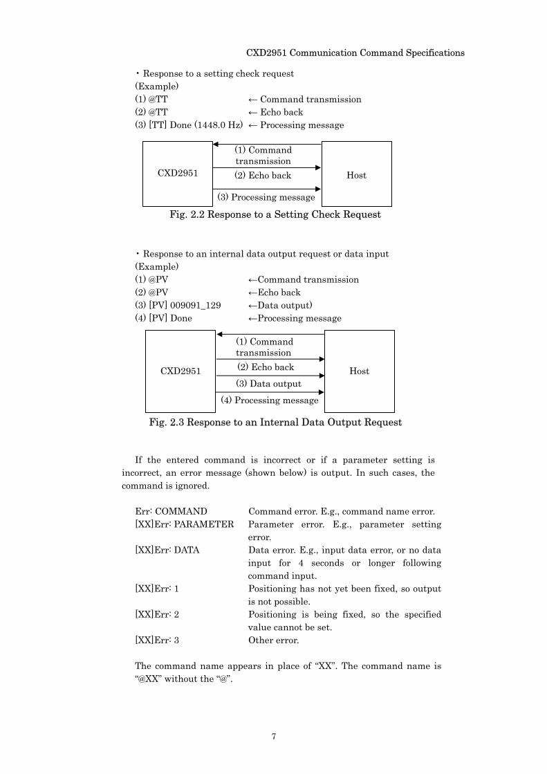
• Response to a setting check request (Example) (1) @TT ← Command transmission (2) @TT ← Echo back (3) [TT] Done (1448.0 Hz) ← Processing message • Response to an internal data output request or data input (Example) (1) @PV ←Command transmission (2) @PV ←Echo back (3) [PV] 009091_129 ←Data output) (4) [PV] Done ←Processing message If the entered command is incorrect or if a parameter setting is
incorrect, an error message (shown below) is output. In such cases, the command is ignored.
Err: COMMAND Command error. E.g., command name error. [XX]Err: PARAMETER Parameter error. E.g., parameter setting
error. [XX]Err: DATA Data error. E.g., input data error, or no data
input for 4 seconds or longer following command input.
[XX]Err: 1 Positioning has not yet been fixed, so output is not possible.
[XX]Err: 2 Positioning is being fixed, so the specified value cannot be set.
[XX]Err: 3 Other error. The command name appears in place of “XX”. The command name is “@XX” without the “@”.
Host
CXD2951
(1) Command transmission (2) Echo back
(3) Processing message
Fig. 2.2 Response to a Setting Check Request
Host
CXD2951
(1) Command transmission (2) Echo back
(3) Data output
(4) Processing message
Fig. 2.3 Response to an Internal Data Output Request
CXD2951 Communication Command Specifications
8
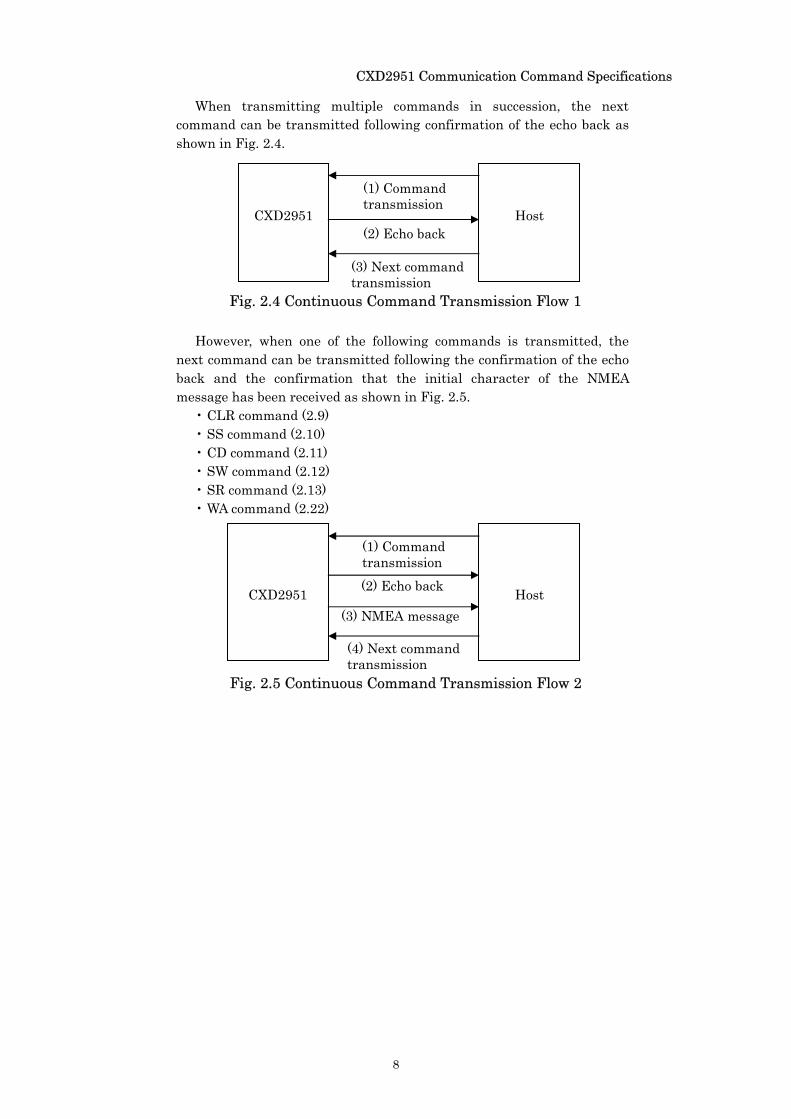
When transmitting multiple commands in succession, the next command can be transmitted following confirmation of the echo back as shown in Fig. 2.4.
However, when one of the following commands is transmitted, the next command can be transmitted following the confirmation of the echo back and the confirmation that the initial character of the NMEA message has been received as shown in Fig. 2.5.
• CLR command (2.9) • SS command (2.10) • CD command (2.11) • SW command (2.12) • SR command (2.13) • WA command (2.22)
Fig. 2.4 Continuous Command Transmission Flow 1
CXD2951
Host (2) Echo back
(1) Command transmission
(3) Next command transmission
CXD2951
Host (2) Echo back
(3) NMEA message
(1) Command transmission
(4) Next command transmission
Fig. 2.5 Continuous Command Transmission Flow 2
CXD2951 Communication Command Specifications
9
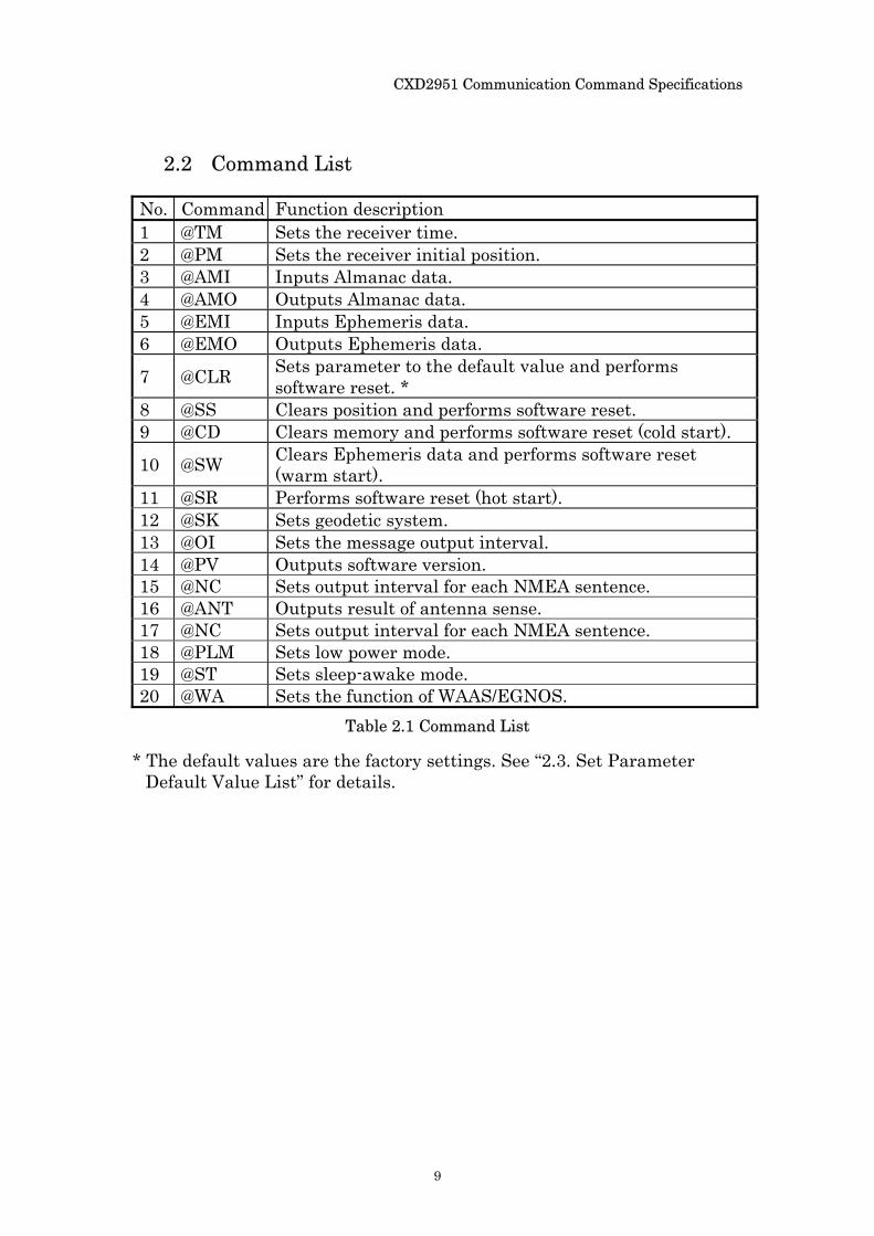
2.2 Command List
No. Command Function description 1 @TM Sets the receiver time. 2 @PM Sets the receiver initial position. 3 @AMI Inputs Almanac data. 4 @AMO Outputs Almanac data. 5 @EMI Inputs Ephemeris data. 6 @EMO Outputs Ephemeris data.
7 @CLR Sets parameter to the default value and performs software reset. *
8 @SS Clears position and performs software reset. 9 @CD Clears memory and performs software reset (cold start).
10 @SW Clears Ephemeris data and performs software reset (warm start).
11 @SR Performs software reset (hot start). 12 @SK Sets geodetic system. 13 @OI Sets the message output interval. 14 @PV Outputs software version. 15 @NC Sets output interval for each NMEA sentence. 16 @ANT Outputs result of antenna sense. 17 @NC Sets output interval for each NMEA sentence. 18 @PLM Sets low power mode. 19 @ST Sets sleep-awake mode. 20 @WA Sets the function of WAAS/EGNOS.
* The default values are the factory settings. See “2.3. Set Parameter
Default Value List” for details.
Table 2.1 Command List
CXD2951 Communication Command Specifications
10
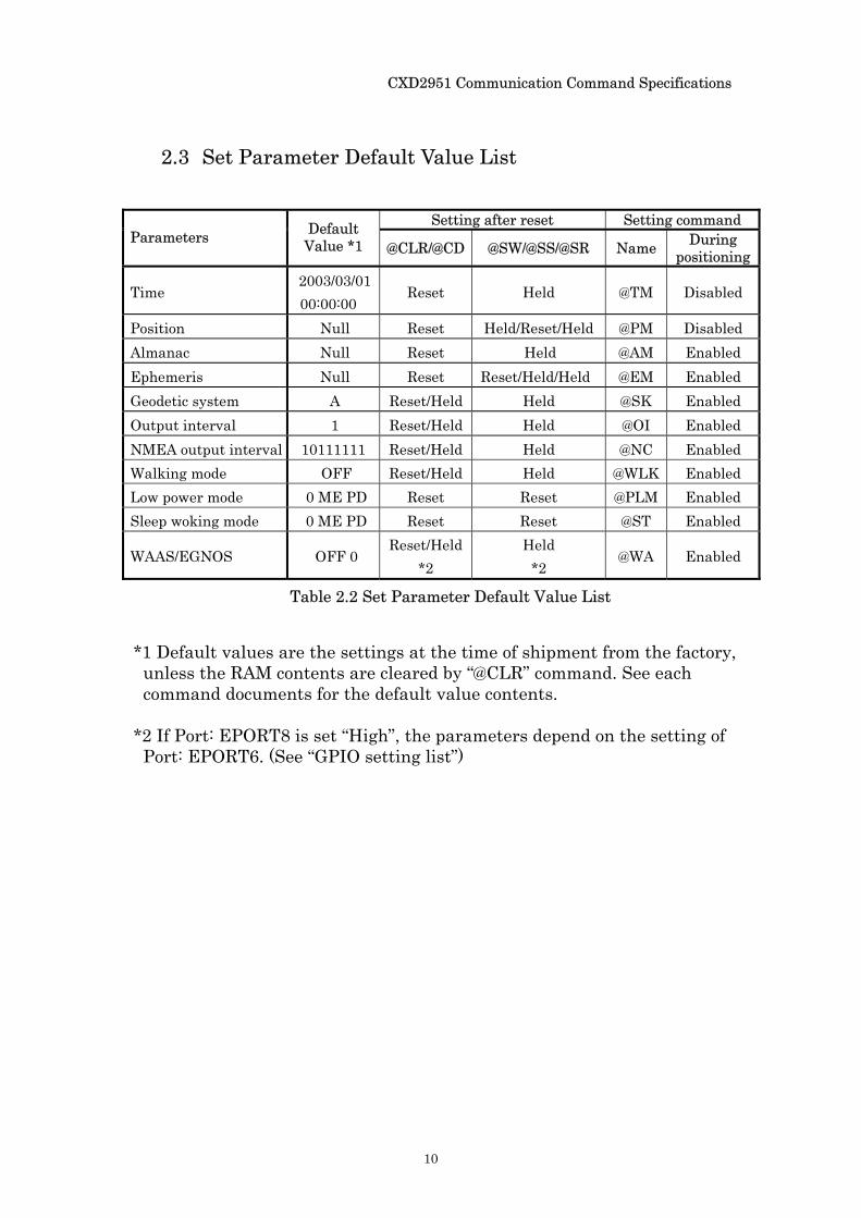
2.3 Set Parameter Default Value List
Setting after reset Setting command
Parameters Default Value *1 @CLR/@CD @SW/@SS/@SR Name During
positioning
Time 2003/03/01 00:00:00
Reset Held @TM Disabled
Position Null Reset Held/Reset/Held @PM Disabled Almanac Null Reset Held @AM Enabled Ephemeris Null Reset Reset/Held/Held @EM Enabled Geodetic system A Reset/Held Held @SK Enabled Output interval 1 Reset/Held Held @OI Enabled NMEA output interval 10111111 Reset/Held Held @NC Enabled Walking mode OFF Reset/Held Held @WLK Enabled Low power mode 0 ME PD Reset Reset @PLM Enabled Sleep woking mode 0 ME PD Reset Reset @ST Enabled
WAAS/EGNOS OFF 0 Reset/Held
*2 Held
*2 @WA Enabled
*1 Default values are the settings at the time of shipment from the factory,
unless the RAM contents are cleared by “@CLR” command. See each command documents for the default value contents.
*2 If Port: EPORT8 is set “High”, the parameters depend on the setting of
Port: EPORT6. (See “GPIO setting list”)
Table 2.2 Set Parameter Default Value List
CXD2951 Communication Command Specifications
11
2.4 Command Notation Method
The following notation method is used in the command usage methods explained in the following sections.
[A|B|C]: One of A, B or C must be selected. [A]: A can be selected as an option.
Do not input the brackets “[ ]”.
CXD2951 Communication Command Specifications
12
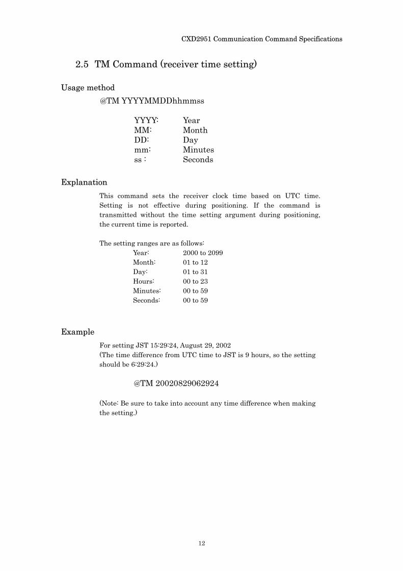
2.5 TM Command (receiver time setting)
Usage method @TM YYYYMMDDhhmmss
YYYY: Year MM: Month DD: Day mm: Minutes ss : Seconds
Explanation This command sets the receiver clock time based on UTC time. Setting is not effective during positioning. If the command is transmitted without the time setting argument during positioning, the current time is reported. The setting ranges are as follows:
Year: 2000 to 2099 Month: 01 to 12 Day: 01 to 31 Hours: 00 to 23 Minutes: 00 to 59 Seconds: 00 to 59
Example For setting JST 15:29:24, August 29, 2002 (The time difference from UTC time to JST is 9 hours, so the setting should be 6:29:24.)
@TM 20020829062924
(Note: Be sure to take into account any time difference when making the setting.)
CXD2951 Communication Command Specifications
13
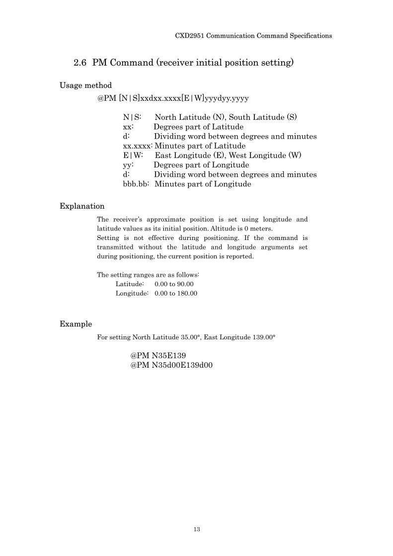
2.6 PM Command (receiver initial position setting)
Usage method @PM [N|S]xxdxx.xxxx[E|W]yyydyy.yyyy
N|S: North Latitude (N), South Latitude (S) xx: Degrees part of Latitude d: Dividing word between degrees and minutes xx.xxxx: Minutes part of Latitude
E|W: East Longitude (E), West Longitude (W) yy: Degrees part of Longitude d: Dividing word between degrees and minutes bbb.bb: Minutes part of Longitude
Explanation The receiver’s approximate position is set using longitude and latitude values as its initial position. Altitude is 0 meters. Setting is not effective during positioning. If the command is transmitted without the latitude and longitude arguments set during positioning, the current position is reported.
The setting ranges are as follows:
Latitude: 0.00 to 90.00 Longitude: 0.00 to 180.00
Example For setting North Latitude 35.00°, East Longitude 139.00°
@PM N35E139 @PM N35d00E139d00
CXD2951 Communication Command Specifications
14
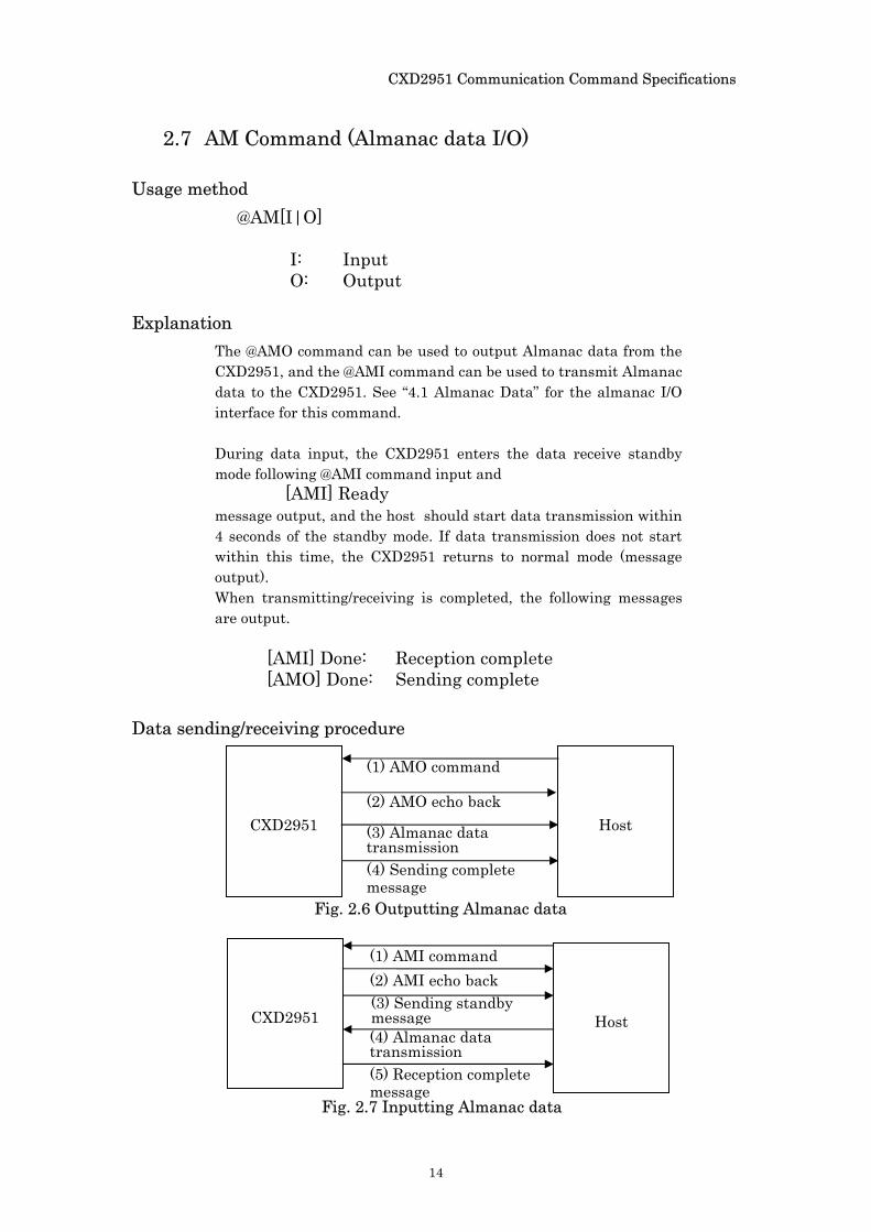
2.7 AM Command (Almanac data I/O)
Usage method @AM[I|O]
I: Input O: Output
Explanation The @AMO command can be used to output Almanac data from the CXD2951, and the @AMI command can be used to transmit Almanac data to the CXD2951. See “4.1 Almanac Data” for the almanac I/O interface for this command.
During data input, the CXD2951 enters the data receive standby mode following @AMI command input and
[AMI] Ready message output, and the host should start data transmission within 4 seconds of the standby mode. If data transmission does not start within this time, the CXD2951 returns to normal mode (message output). When transmitting/receiving is completed, the following messages are output.
[AMI] Done: Reception complete [AMO] Done: Sending complete
Data sending/receiving procedure
CXD2951
Host
Fig. 2.6 Outputting Almanac data
(1) AMO command
(2) AMO echo back (3) Almanac data transmission (4) Sending complete message
Fig. 2.7 Inputting Almanac data
CXD2951
Host
(1) AMI command
(4) Almanac data transmission
(2) AMI echo back
(5) Reception complete message
(3) Sending standby message
CXD2951 Communication Command Specifications
15
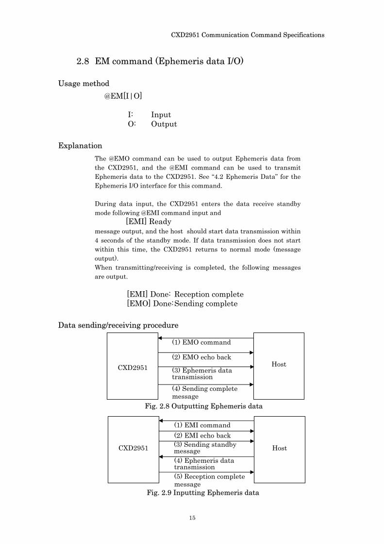
2.8 EM command (Ephemeris data I/O)
Usage method @EM[I|O]
I: Input O: Output
Explanation The @EMO command can be used to output Ephemeris data from the CXD2951, and the @EMI command can be used to transmit Ephemeris data to the CXD2951. See “4.2 Ephemeris Data” for the Ephemeris I/O interface for this command. During data input, the CXD2951 enters the data receive standby mode following @EMI command input and
[EMI] Ready message output, and the host should start data transmission within 4 seconds of the standby mode. If data transmission does not start within this time, the CXD2951 returns to normal mode (message output). When transmitting/receiving is completed, the following messages are output.
[EMI] Done: Reception complete [EMO] Done: Sending complete
Data sending/receiving procedure
Fig. 2.9 Inputting Ephemeris data
Fig. 2.8 Outputting Ephemeris data
CXD2951
Host
(1) EMO command
(2) EMO echo back (3) Ephemeris data transmission (4) Sending complete message
CXD2951
Host
(1) EMI command (2) EMI echo back
(4) Ephemeris data transmission (5) Reception complete message
(3) Sending standby message
CXD2951 Communication Command Specifications
16
2.9 CLR command (clear set parameters)
Usage method @CLR
Explanation This command resets the user-set parameters to the default values; clears the time, position, Almanac data, Ephemeris data, and TCXO offset value; and restarts the equipment. See Table 2.2 for the user-set parameter default values.
CXD2951 Communication Command Specifications
17
2.10 SS command (clear position)
Usage method @SS
Explanation This command clears the position and resets the software. While some user-set parameters are held, others return to the default values. See Table 2.2. This command may shorten the position fix time when long-distance travel occurs from the last fixed position.
Note NMEA message continues outputting the last position after command execution.
CXD2951 Communication Command Specifications
18
2.11 CD command (cold start)
Usage method @CD
Explanation This command performs a cold start reset. Cold start resetting clears the time, position, Almanac data, Ephemeris data, and TCXO offset value; and resets the software. While some user-set parameters are held, others return to the default values. See Table 2.
CXD2951 Communication Command Specifications
19
2.12 SW command (warm start)
Usage method @SW
Explanation This command performs a warm start reset. Warm start resetting clears the Ephemeris data and resets the software. While some user-set parameters are held, others return to the default values. See Table 2.2.
Note If the CXD2951 does not have Almanac data from four or more visible satellites, a cold start is performed instead .
CXD2951 Communication Command Specifications
20
2.13 SR command (hot start)
Usage method @SR
Explanation This command performs a hot start reset. Hot start resets the software while retaining the time, initial position, Almanac data, Ephemeris data, and TCXO offset value.) While some user-set parameters are held, others return to the default values. See Table 2.2.
Note If the CXD2951 does not have Ephemeris data from four or more visible satellites, then a warm start is performed instead. If the CXD2951 does not have Almanac data from four or more visible satellites, then a cold start is performed.
CXD2951 Communication Command Specifications
21
2.14 SK command (geodetic system setting)
Usage method @SK [A|B]
A: WGS-84 B: Tokyo geodetic system
Explanation This command sets the geodetic system used for outputting position information. Two different geodetic systems can be set: WGS-84 and the Tokyo geodetic system. The default setting is WGS84. If the geodetic system argument is not set, the current setting value is reported. The setting is held internally even if the @CD, @SW, @SS or @SR reset commands are transmitted. The default value is A (WGS-84).
Example Changing to the Tokyo geodetic system
@SK B
CXD2951 Communication Command Specifications
22
2.15 OI command (message output interval setting)
Usage method @OI interval
interval: [0|1|2|5|10]
Explanation This command changes the output interval of positioning result messages. The settings are 0, 1, 2, 5, and 10 seconds. If 0 is set, message reporting isn’t outputted. To resume output, set a value other than 0. If the interval value argument is not set, the current setting is reported. The setting is held internally even if the @CD, @SW, @SS or @SR reset commands are transmitted. The default value is 1.
Example Setting the output interval to every 5 seconds
@OI 5
CXD2951 Communication Command Specifications
23
2.16 PV command (outputting the software version)
Usage method @PV
Explanation This command outputs the software version.
Example @PV ← command Input
The following is output:
[PV] 009091_129
CXD2951 Communication Command Specifications
24
2.17 NC command (NMEA sentence output interval setting)
Usage method @NC dddddddd
d: [0|1|2|5]
Explanation This command sets the output intervals for individual NMEA sentences (GGA, GLL, GSA, GSV, RMC, VTG, ZDA) and SONY original sentence PSGSA. The command requires 8 integer values (0, 1, 2, 5). The first number indicates the GGA output interval; the second indicates the GLL output interval; the third indicates the GSA output interval; the fourth indicates the GSV output interval; the fifth indicates the RMC output interval; the sixth indicates the VTG output interval; the seventh indicates the ZDA output interval; and the eighth indicates the PSGSA output interval. There are four different interval settings: 0, 1, 2, and 5. If 0 is set, the message is not output. If any output interval arguments are not set, the current setting is used. The setting is held internally even if the @CD, @SW, @SS or @SR reset commands are transmitted. The default setting is 10111111. (GGA, GSA, GSV, RMC, VTG, ZDA and PSGSA are output every second; GLL is not.)
Example To output GGA every time and output GSA once every two times:
@NC 10200000
CXD2951 Communication Command Specifications
25
2.18 ANT command (reporting the antenna state)
Usage method @ANT
Explanation This command reports the antenna state when the antenna sensing function is performed.
[ANT] Normal: Normal
[ANT] Open: The antenna is disconnected. Open state. [ANT] Short: The antenna connector is shorted [ANT] Done(OFF): Antenna sensing is off Antenna sense is performed at intervals of 1 second. If a short is detected, Port: EPORT12 inverts (from low to high) for about 3 seconds until next sensing. After that, the port output returns to the original level (low) and antenna sensing is performed again.
Note Antenna sense isn’t performed during the sleep state in the low power consumption mode, i.e. the sleep-awake mode. Antenna sense is performed unless the software is in the sleep state.
Example Reporting the antenna state
@ANT
CXD2951 Communication Command Specifications
26
2.19 WLK command (walking mode setting)
Usage method @WLK [ON|OFF]
ON: Start walking mode OFF: Cancel walking mode
Explanation This command sets the walking mode for the position filter. If the argument is not set, the current setting is used. The settings are held internally even if the @CD, @SW, @SS or @SR reset commands are transmitted. The default is off.
Example Setting the walking mode for the position filter
@WLK ON
CXD2951 Communication Command Specifications
27
2.20 PLM command (low power mode setting)
Usage method @PLM [0|5..10] [MD|ME] [PD|PE]
T: [0|5..10] interval time of positioning MD: stop message in interval time ME: output message in interval time PD: not control EPORT12 synchronized with sleeping PE: control EPORT12 synchronized with sleeping
Explanation This command sets the low power mode. If the low power mode is requested, the position update will be intermittent as specified. Interval time settings are 0, 5, 6, 7, 8, 9, 10 [sec]. If 0 is set, the low power mode is terminated and the CXD2951 operates at the normal mode. If ME is set, NMEA messages are generated periodically at 1Hz.. Set MD if NMEA messages are not needed between the positioning updates. If PE is set, Port: EPORT12 level is synchronized with low power operation mode. EPORT12 is HIGH when the CXD2951 is in “inactive” state. When the CXD2951 goes back to the “active” state, the port takes on the previous state before “inactive” state depended on antenna sense function. If the all arguments are not set, the current setting is reported. If MD or ME, PD or PE is not set, the previous setting is held. Default setting will be selected after the @CD, @SW, @SS or @SR commands. The default values are Interval time: 0(normal mode) Message output: ME Port control: PD
Note This command cannot be used with the sleep-awake mode at the same time. If the sleep-awake mode is set when the low power mode is performed, the low power mode will be cancelled and the sleep-awake mode will be performed. Do not use @OI, @WA command at the same time.
Example Setting 10 seconds interval positioning, NEMA messages output in interval time too and port control
@PLM 10 ME PE
CXD2951 Communication Command Specifications
28
2.21 ST command (sleep-awake mode setting)
Usage method @ST T [MD|ME] [PD|PE]
T: [0|5..10] interval time of positioning MD: stop message in interval time ME: output message in interval time PD: not control EPORT12 synchronized with sleeping PE: control EPORT12 synchronized with sleeping
Explanation This command sets sleep-awake mode. If the sleep-awake mode is performed, the position update will be intermittent as specified.
Interval time settings are 0, 5, 6, 7, 8, 9, 10 [sec]. If 0 is set, the low power mode is terminated and the CXD2951 operates at the normal mode. If ME is set, NMEA messages are generated periodically at 1Hz. Set MD if NMEA messages are not needed between the positioning updates. If PE is set, Port: EPORT12 level is synchronized with low sleep-awake mode operation. EPORT12 is HIGH when the CXD2951 is in “inactive” state. . When the CXD2951 is back in “active” state, the port takes on the previous state before “inactive” state depended on antenna sense function.
If the all argument is not set, the current setting is reported. If MD or ME, PD or PE is not set, the previous setting is held. Default setting selected with the @CD, @SW, @SS or @SR commands. The default values are
Interval time: 0(normal mode) Message output: ME Port control: PD
Note This command cannot be used with the low power mode at the same time. If the low power mode is set when the sleep-awake mode is performed, the sleep-awake mode will be cancelled and the low power mode will be performed.
Set this command after the positioning is succeeded. If this mode is set while the positioning is not succeeded, the position will not be succeeded after setting too. And while this mode is performed, the ephemeris data are not updated. Cancel this mode if the non-positioning is continued.
Do not use @OI, @WA command at the same time.
Example Setting 10 seconds interval positioning, NEMA messages output in interval time too time and port control
@ST 10 ME PE
CXD2951 Communication Command Specifications
29
2.22 WA command (WAAS/EGNOS function setting)
Usage method @WA [ON|OFF] [PRN]
ON: WAAS/EGNOS function ON OFF: WAAS/EGNOS function OFF PRN: [0|120..138] WAAS/EGNOS PRN number
Explanation This command sets the WAAS/EGNOS function. When set to ON, the CXD2951 receives WAAS/EGNOS satellite signals from specified PRN number (satellite). Correction information is downloaded after the initial position measurement. The CXD2951 outputs the corrected position once the information is decoded. PRN number is the WAAS/EGNOS satellite number. If 0 is set, the highest elevation angle WAAS/EGNOS satellite is automatically selected. When no argument is set, the current settings are output. When PRN is not set, the previous settings are kept. The setting is held internally even if the @CD, @SW, @SS or @SR commands are transmitted. The default values are
WAAS/EGNOS function : OFF PRN : 0 (automatic WAAS/EGNOS satellite
selection)
Note If WAAS/EGNOS function is set to ON from OFF or it is set to OFF from ON, a software reset is performed. Since WAAS/EGNOS function can also be set to ON by the port setting, user have to set Port:EPORT8 to “Low” in order to use @WA command.
Example WAAS/EGNOS function is set to ON with automatic WAAS/EGNOS satellite selection.
@WA ON 0
CXD2951 Communication Command Specifications
30
Chapter 3 Output Messages This chapter describes output messages for CXD2951.
CXD2951 outputs messages in NMEA0183 (Ver. 3.01) format.
3.1. NMEA0183 Format
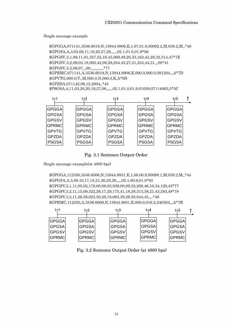
CXD2951 can output 8 different types of sentence: GPGGA, GPGLL, GPGSA, GPGSV, GPRMC, GPVTG, GPZDA and PSGSA. If 9600bps or 19200bps or 38400bps baud rate is set for port setting (EPORT1.3), it outputs 7 types of sentence: GPGGA, GPGSA, GPGSV, GPRMC, GPVTG, GPZDA, PSGSA as default (fig. 3.1). Moreover, if 4800bps baud rate is set, it outputs 4 types of sentences: GPGGA, GPGSA, GPGSV, GPRMC as default (fig. 3.2).
Please use @NC command (2.18) if output sentence should be needed
to change.
Notice: When the baud rate is set for port setting, NMEA message may not be outputted correctly in some cases. In this case, please execute @CLR command (2.11).
For 4800bps baud rate, it cannot output all 8 sentences of NMEA within 1 sec. As a rough guide, select less than 6 sentences for this baud rate.
CXD2951 Communication Command Specifications
31
Single message example
$GPGGA,071141,3536.6019,N,13944.8906,E,1,07,01.0,00092.2,M,039.2,M,,*46 $GPGSA,A,3,03,08,11,19,20,27,28,,,,,,02.1,01.0,01.9*06 $GPGSV,3,1,09,11,81,327,52,19,43,069,49,20,33,163,45,28,32,314,47*7E $GPGSV,3,2,09,03,18,093,42,08,29,254,43,27,21,234,44,31,,,00*41 $GPGSV,3,3,09,07,,,00,,,,,,,,,,,,*77 $GPRMC,071141,A,3536.6019,N,13944.8906,E,000.0,000.0,091204,,,A*7D $GPVTG,000.0,T,,M,000.0,N,000.0,K,A*0D $GPZDA,071142,09,12,2004,,*45 $PSGSA,4,11,03,28,20,19,27,08,,,,,,02.1,01.0,01.9,01028,07114063,5*5C
Single message example(at 4800 bps)
$GPGGA,112350,3536.6006,N,13944.8931,E,1,08,00.9,00098.1,M,039.2,M,,*44 $GPGSA,A,3,09,10,17,18,21,26,28,29,,,,,02.1,00.9,01.8*00 $GPGSV,3,1,11,05,02,178,00,08,03,039,00,09,52,208,46,10,34,120,43*77 $GPGSV,3,2,11,15,09,322,26,17,20,175,41,18,28,313,38,21,43,283,48*78 $GPGSV,3,3,11,26,59,023,50,28,18,063,39,29,50,044,45,,,,*46 $GPRMC,112350,A,3536.6006,N,13944.8931,E,000.0,016.2,240304,,,A*7B
Fig. 3.1 Sentence Output Order
GPGGA GPGSA GPGSV GPRMC GPVTG GPZDA PSGSA
GPGGA GPGSA GPGSV GPRMC GPVTG GPZDA PSGSA
t+1 t+2 t+3 t+4 t+5 T
GPGGAGPGSAGPGSVGPRMCGPVTGGPZDAPSGSA
GPGGAGPGSAGPGSVGPRMCGPVTGGPZDAPSGSA
GPGGA GPGSA GPGSV GPRMC GPVTG GPZDA PSGSA
Fig. 3.2 Sentence Output Order (at 4800 bps)
t+1 t+2 t+3 t+4 t+5 T
GPGGA GPGSA GPGSV GPRMC
GPGGA GPGSA GPGSV GPRMC
GPGGAGPGSAGPGSVGPRMC
GPGGAGPGSAGPGSVGPRMC
GPGGA GPGSA GPGSV GPRMC
CXD2951 Communication Command Specifications
32
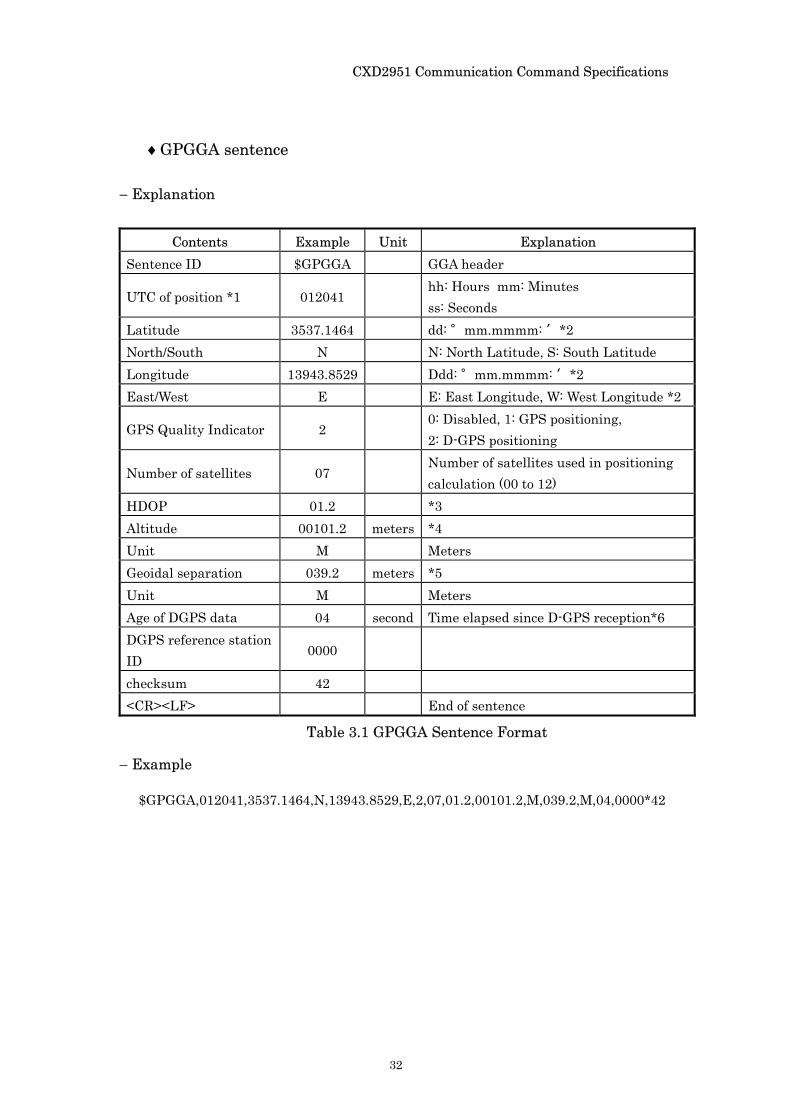
♦GPGGA sentence
− Explanation
Contents Example Unit Explanation Sentence ID $GPGGA GGA header
UTC of position *1 012041 hh: Hours mm: Minutes ss: Seconds
Latitude 3537.1464 dd: °mm.mmmm: ′*2 North/South N N: North Latitude, S: South Latitude Longitude 13943.8529 Ddd: °mm.mmmm: ′*2 East/West E E: East Longitude, W: West Longitude *2
GPS Quality Indicator 2 0: Disabled, 1: GPS positioning, 2: D-GPS positioning
Number of satellites 07 Number of satellites used in positioning calculation (00 to 12)
HDOP 01.2 *3 Altitude 00101.2 meters *4 Unit M Meters Geoidal separation 039.2 meters *5 Unit M Meters Age of DGPS data 04 second Time elapsed since D-GPS reception*6 DGPS reference station ID
0000
checksum 42 <CR><LF> End of sentence
− Example
$GPGGA,012041,3537.1464,N,13943.8529,E,2,07,01.2,00101.2,M,039.2,M,04,0000*42
Table 3.1 GPGGA Sentence Format
CXD2951 Communication Command Specifications
33
− Note *1 During non-position fixes, this value is increased from the last position
calculation time by one second. *2 The Longitude is always expressed as 0 degree when the Latitude is 90
degree, and is expressed as Longitude 0(180) degree East when the Longitude is 0(180) degree West.
*3 The DOP value is expressed as two integer digits and one decimal digit. Values 99.9 and higher are expressed as 99.9.
*4 The elevation is expressed as five integer digits and one decimal digit. Values of 99999.9 or more (–99999.9 or less) are expressed as 99999.9 (–99999.9).
*5 The difference from the geoidal surface is expressed as three integer digits and one decimal digit.
*6 The DGPS Age is expressed as two integer digits.

CXD2951 Communication Command Specifications
34
♦GPGLL sentence
− Explanation
− Example
$GPGLL,3537.1483,N,13943.8511,E,034639,A,A*41 − Note
*1 The Longitude is always expressed as 0 degree when the Latitude is 90 degree, and is expressed as Longitude 0(180) degree East when the Longitude is 0(180) degree West.
*2 During non-position fixes, this value is increased from the last position calculation time by one second.
*3 Position system mode indicator
Contents Example Unit Explanation Sentence ID $GPGLL GLL header Latitude 3537.1483 dd: °mm.mmmm: ′ North/South N N: North Latitude, S: South Latitude Longitude 13943.8511 ddd: °mm.mmmm: ′ *1 East/West E E: East Longitude, W: West Longitude *1 UTC of position *2 034639 hh: Hours mm: Minutes ss: Seconds Status A A: Data valid, V: Data invalid
Mode Indicator A A: Autonomous, D: D-GPS, N: Data not valid *3
checksum 41 <CR><LF> End of sentence
Table 3.2 GPGLL Sentence format
CXD2951 Communication Command Specifications
35
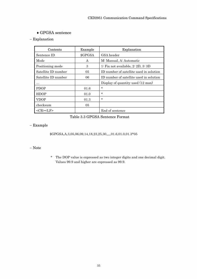
♦GPGSA sentence − Explanation
Contents Example Explanation
Sentence ID $GPGSA GSA header Mode A M: Manual, A: Automatic Positioning mode 3 1: Fix not available, 2: 2D, 3: 3D Satellite ID number 05 ID number of satellite used in solution Satellite ID number 06 ID number of satellite used in solution … Display of quantity used (12 max) PDOP 01.6 * HDOP 01.0 * VDOP 01.3 * checksum 05 <CR><LF> End of sentence
− Example
$GPGSA,A,3,05,06,09,14,18,23,25,30,,,,,01.6,01.0,01.3*05
− Note
* The DOP value is expressed as two integer digits and one decimal digit. Values 99.9 and higher are expressed as 99.9.
Table 3.3 GPGSA Sentence Format
CXD2951 Communication Command Specifications
36
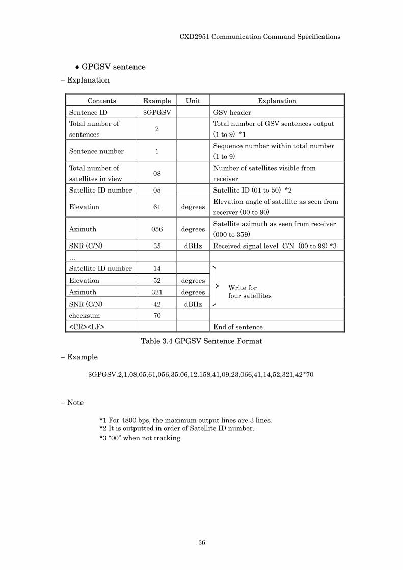
♦GPGSV sentence − Explanation
Contents Example Unit Explanation
Sentence ID $GPGSV GSV header Total number of sentences
2 Total number of GSV sentences output (1 to 9) *1
Sentence number 1 Sequence number within total number (1 to 9)
Total number of satellites in view
08 Number of satellites visible from receiver
Satellite ID number 05 Satellite ID (01 to 50) *2
Elevation 61 degrees Elevation angle of satellite as seen from receiver (00 to 90)
Azimuth 056 degrees Satellite azimuth as seen from receiver (000 to 359)
SNR (C/N) 35 dBHz Received signal level C/N (00 to 99) *3 … Satellite ID number 14 Elevation 52 degrees Azimuth 321 degrees SNR (C/N) 42 dBHz
checksum 70 <CR><LF> End of sentence
− Example
$GPGSV,2,1,08,05,61,056,35,06,12,158,41,09,23,066,41,14,52,321,42*70
− Note
*1 For 4800 bps, the maximum output lines are 3 lines. *2 It is outputted in order of Satellite ID number. *3 “00” when not tracking
Write for four satellites
Table 3.4 GPGSV Sentence Format
CXD2951 Communication Command Specifications
37
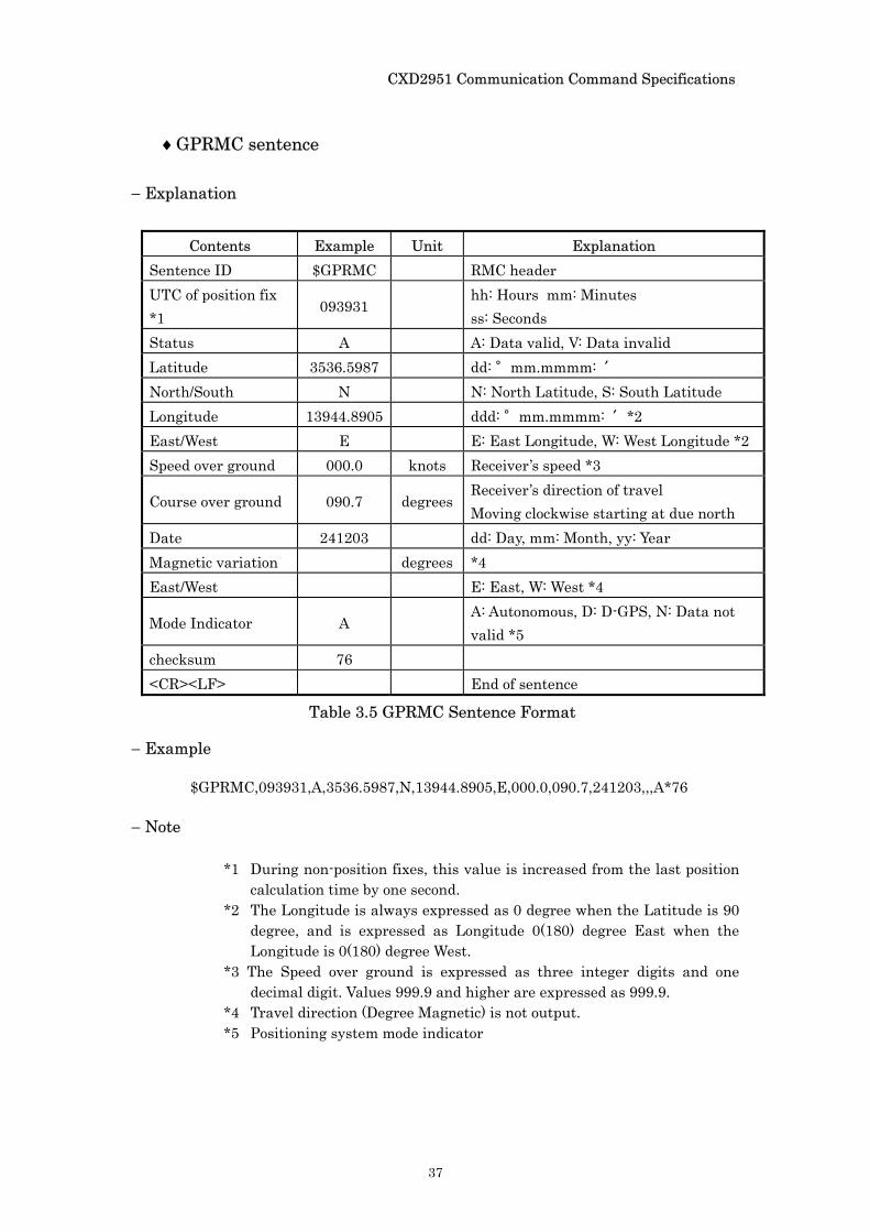
♦GPRMC sentence
− Explanation
Contents Example Unit Explanation Sentence ID $GPRMC RMC header UTC of position fix *1
093931 hh: Hours mm: Minutes ss: Seconds
Status A A: Data valid, V: Data invalid Latitude 3536.5987 dd: °mm.mmmm: ′ North/South N N: North Latitude, S: South Latitude Longitude 13944.8905 ddd: °mm.mmmm: ′*2 East/West E E: East Longitude, W: West Longitude *2 Speed over ground 000.0 knots Receiver’s speed *3
Course over ground 090.7 degrees Receiver’s direction of travel Moving clockwise starting at due north
Date 241203 dd: Day, mm: Month, yy: Year Magnetic variation degrees *4 East/West E: East, W: West *4
Mode Indicator A A: Autonomous, D: D-GPS, N: Data not valid *5
checksum 76 <CR><LF> End of sentence
− Example
$GPRMC,093931,A,3536.5987,N,13944.8905,E,000.0,090.7,241203,,,A*76
− Note
*1 During non-position fixes, this value is increased from the last position calculation time by one second.
*2 The Longitude is always expressed as 0 degree when the Latitude is 90 degree, and is expressed as Longitude 0(180) degree East when the Longitude is 0(180) degree West.
*3 The Speed over ground is expressed as three integer digits and one decimal digit. Values 999.9 and higher are expressed as 999.9.
*4 Travel direction (Degree Magnetic) is not output. *5 Positioning system mode indicator
Table 3.5 GPRMC Sentence Format
CXD2951 Communication Command Specifications
38
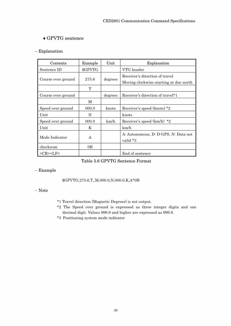
♦GPVTG sentence − Explanation
Contents Example Unit Explanation Sentence ID $GPVTG VTG header
Course over ground 275.6 degrees Receiver’s direction of travel Moving clockwise starting at due north
T Course over ground degrees Receiver’s direction of travel*1 M Speed over ground 000.0 knots Receiver’s speed (knots) *2 Unit N knots Speed over ground 000.0 km/h Receiver’s speed (km/h) *2 Unit K km/h
Mode Indicator A A: Autonomous, D: D-GPS, N: Data not valid *3
checksum 0B <CR><LF> End of sentence
− Example
$GPVTG,275.6,T,,M,000.0,N,000.0,K,A*0B − Note
*1 Travel direction (Magnetic Degrees) is not output. *2 The Speed over ground is expressed as three integer digits and one
decimal digit. Values 999.9 and higher are expressed as 999.9. *3 Positioning system mode indicator
Table 3.6 GPVTG Sentence Format
CXD2951 Communication Command Specifications
39
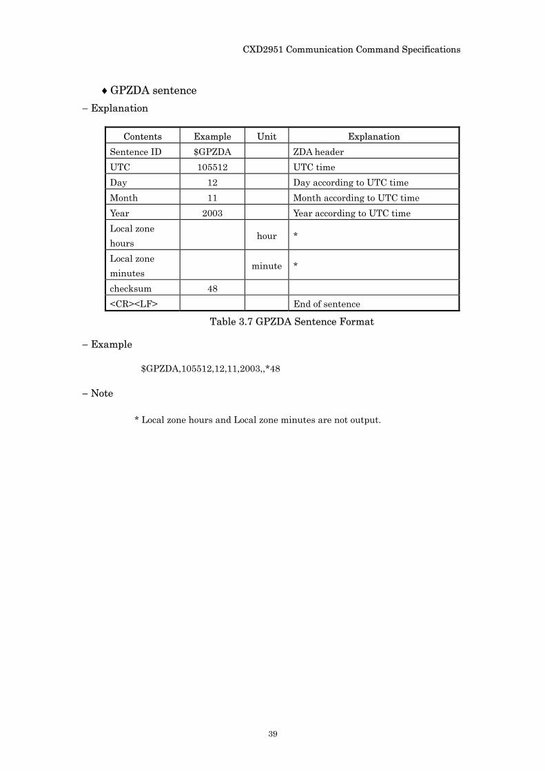
♦GPZDA sentence − Explanation
Contents Example Unit Explanation Sentence ID $GPZDA ZDA header UTC 105512 UTC time Day 12 Day according to UTC time Month 11 Month according to UTC time Year 2003 Year according to UTC time Local zone hours
hour *
Local zone minutes
minute *
checksum 48 <CR><LF> End of sentence
− Example
$GPZDA,105512,12,11,2003,,*48
− Note
* Local zone hours and Local zone minutes are not output.
Table 3.7 GPZDA Sentence Format
CXD2951 Communication Command Specifications
40
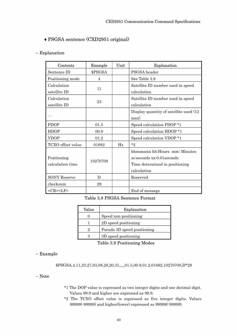
♦PSGSA sentence (CXD2951 original)
− Explanation
Contents Example Unit Explanation Sentence ID $PSGSA PSGSA header Positioning mode 4 See Table 3.9 Calculation satellite ID
11 Satellite ID number used in speed calculation
Calculation satellite ID
23 Satellite ID number used in speed calculation
… Display quantity of satellite used (12 max)
PDOP 01.5 Speed calculation PDOP *1 HDOP 00.9 Speed calculation HDOP *1 VDOP 01.2 Speed calculation VDOP *1 TCXO offset value 01682 Hz *2
Positioning calculation time
10270708
hhmmssxx hh:Hours mm: Minutes ss:seconds xx:0.01seconds Time determined in positioning calculation
SONY Reserve D Reserved checksum 29 <CR><LF> End of message
Value Explanation 0 Speed non-positioning 1 2D speed positioning 2 Pseudo 3D speed positioning 3 3D speed positioning
− Example
$PSGSA,4,11,23,27,03,08,28,20,31,,,,,01.5,00.9,01.2,01682,10270708,D*29
− Note
*1 The DOP value is expressed as two integer digits and one decimal digit. Values 99.9 and higher are expressed as 99.9.
*2 The TCXO offset value is expressed as five integer digits. Values 99999(-99999) and higher(lower) expressed as 99999(-99999).
Table 3.8 PSGSA Sentence Format
Table 3.9 Positioning Modes
CXD2951 Communication Command Specifications
41
3.2. NMEA Message Data Output Specifications
The following table describes the output data configurations in the following positioning states: immediately after cold start, during positioning, during non-positioning and after positioning. See “3.1. NMEA0183 Format” for the output contents of individual sentences.
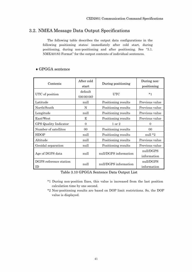
♦GPGGA sentence
Contents After cold
start During positioning
During non-positioning
UTC of position default
(00:00:00) UTC *1
Latitude null Positioning results Previous value North/South N Positioning results Previous value Longitude null Positioning results Previous value East/West E Positioning results Previous value GPS Quality Indicator 0 1 or 2 0 Number of satellites 00 Positioning results 00 HDOP null Positioning results null *2 Altitude null Positioning results Previous value Geoidal separation null Positioning results Previous value
Age of DGPS data null null/DGPS information null/DGPS information
DGPS reference station ID
null null/DGPS information null/DGPS information
*1 During non-position fixes, this value is increased from the last position calculation time by one second.
*2 Non-positioning results are based on DOP limit restrictions. So, the DOP value is displayed.
Table 3.10 GPGGA Sentence Data Output List
CXD2951 Communication Command Specifications
42
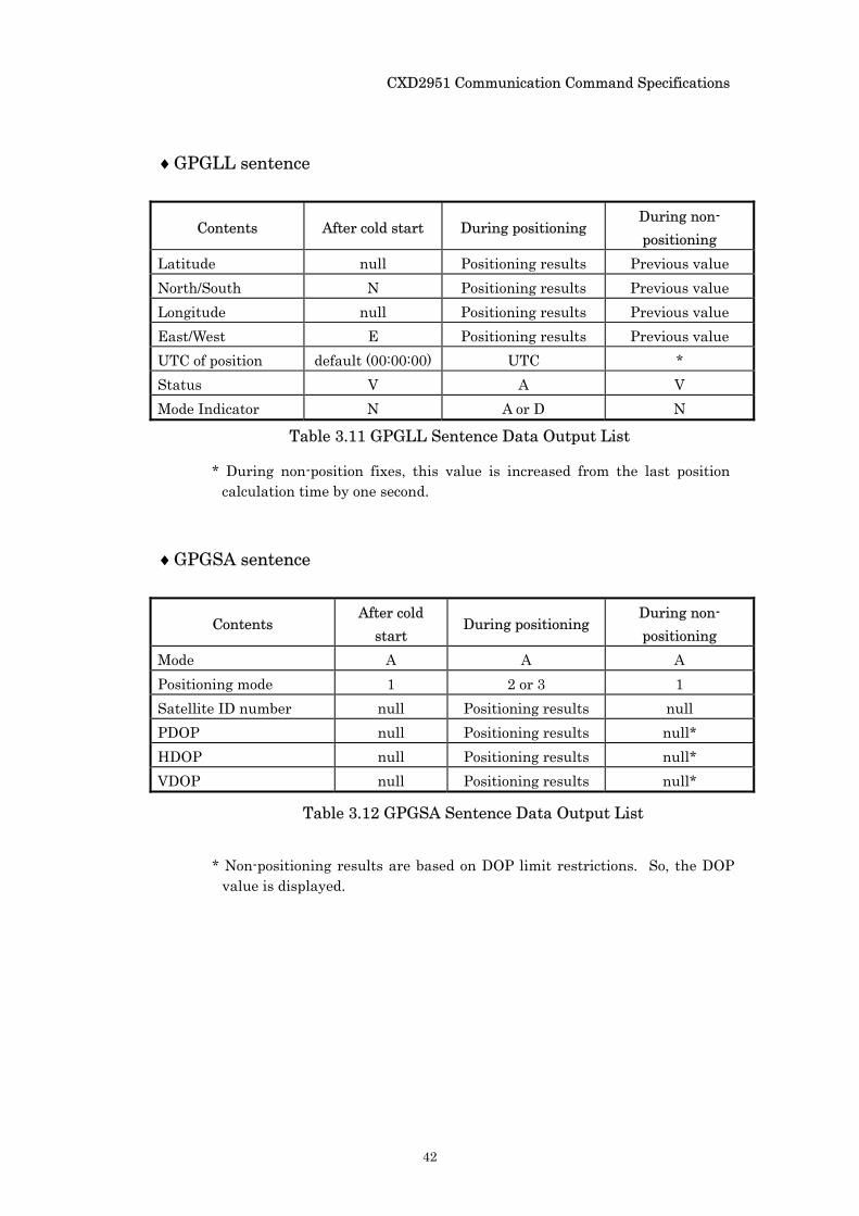
♦GPGLL sentence
Contents After cold start During positioning During non-positioning
Latitude null Positioning results Previous value North/South N Positioning results Previous value Longitude null Positioning results Previous value East/West E Positioning results Previous value UTC of position default (00:00:00) UTC * Status V A V Mode Indicator N A or D N
* During non-position fixes, this value is increased from the last position
calculation time by one second.
♦GPGSA sentence
Contents After cold
start During positioning
During non-positioning
Mode A A A Positioning mode 1 2 or 3 1 Satellite ID number null Positioning results null PDOP null Positioning results null* HDOP null Positioning results null* VDOP null Positioning results null*
* Non-positioning results are based on DOP limit restrictions. So, the DOP
value is displayed.
Table 3.11 GPGLL Sentence Data Output List
Table 3.12 GPGSA Sentence Data Output List
CXD2951 Communication Command Specifications
43
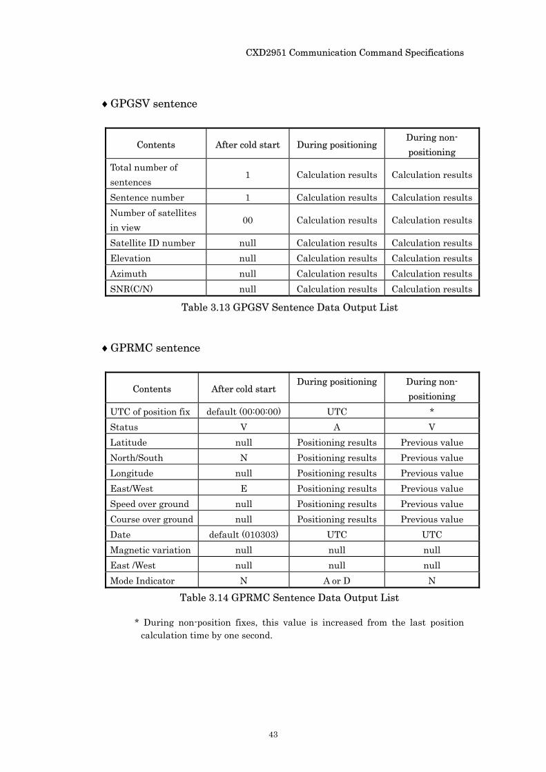
♦GPGSV sentence
Contents After cold start During positioning During non-positioning
Total number of sentences
1 Calculation results Calculation results
Sentence number 1 Calculation results Calculation results Number of satellites in view
00 Calculation results Calculation results
Satellite ID number null Calculation results Calculation results Elevation null Calculation results Calculation results Azimuth null Calculation results Calculation results SNR(C/N) null Calculation results Calculation results
♦GPRMC sentence
Contents After cold start During positioning During non-
positioning UTC of position fix default (00:00:00) UTC * Status V A V Latitude null Positioning results Previous value North/South N Positioning results Previous value Longitude null Positioning results Previous value East/West E Positioning results Previous value Speed over ground null Positioning results Previous value Course over ground null Positioning results Previous value Date default (010303) UTC UTC Magnetic variation null null null East /West null null null Mode Indicator N A or D N
* During non-position fixes, this value is increased from the last position calculation time by one second.
Table 3.13 GPGSV Sentence Data Output List
Table 3.14 GPRMC Sentence Data Output List
CXD2951 Communication Command Specifications
44
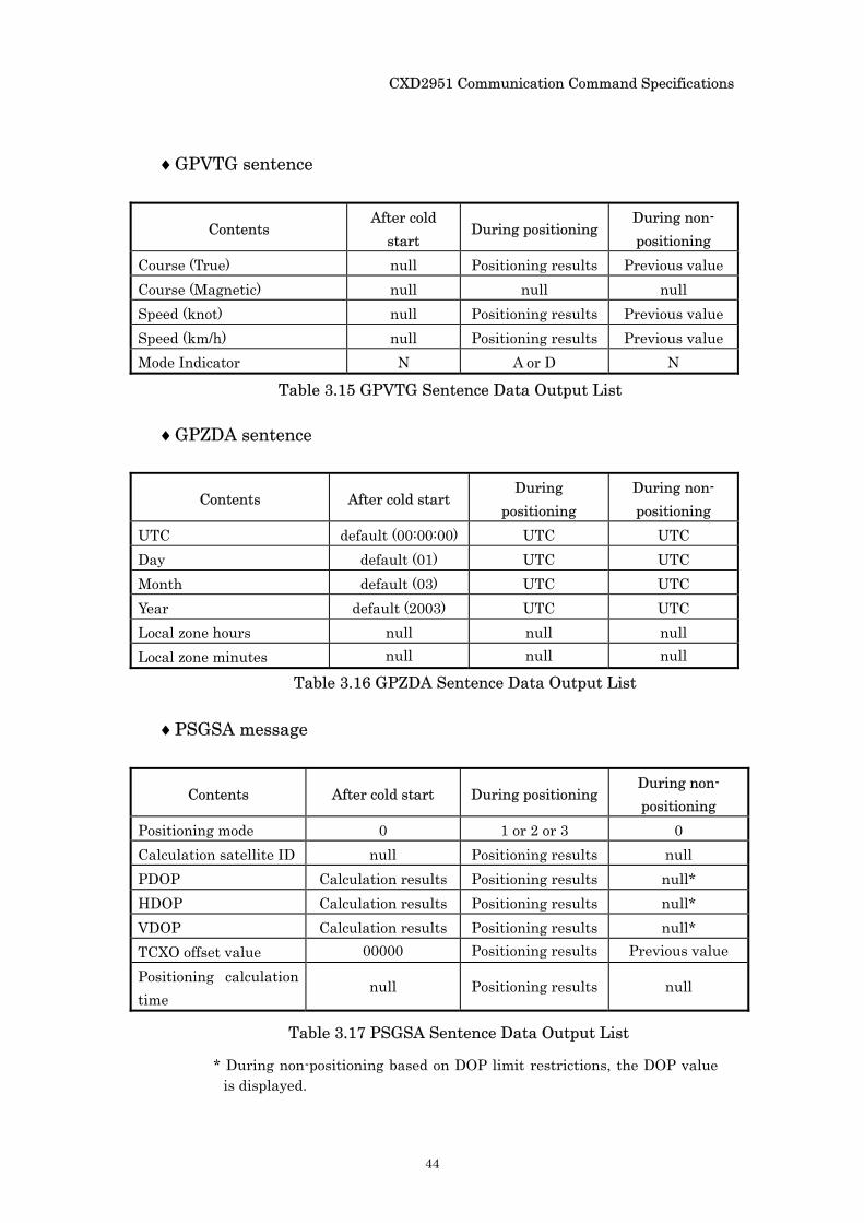
♦GPVTG sentence
Contents After cold
start During positioning
During non-positioning
Course (True) null Positioning results Previous value Course (Magnetic) null null null Speed (knot) null Positioning results Previous value Speed (km/h) null Positioning results Previous value Mode Indicator N A or D N
♦GPZDA sentence
Contents After cold start During
positioning During non-positioning
UTC default (00:00:00) UTC UTC Day default (01) UTC UTC Month default (03) UTC UTC Year default (2003) UTC UTC Local zone hours null null null Local zone minutes null null null
♦PSGSA message
Contents After cold start During positioning During non-positioning
Positioning mode 0 1 or 2 or 3 0 Calculation satellite ID null Positioning results null PDOP Calculation results Positioning results null* HDOP Calculation results Positioning results null* VDOP Calculation results Positioning results null* TCXO offset value 00000 Positioning results Previous value Positioning calculation time
null Positioning results null
* During non-positioning based on DOP limit restrictions, the DOP value
is displayed.
Table 3.15 GPVTG Sentence Data Output List
Table 3.16 GPZDA Sentence Data Output List
Table 3.17 PSGSA Sentence Data Output List
CXD2951 Communication Command Specifications
45
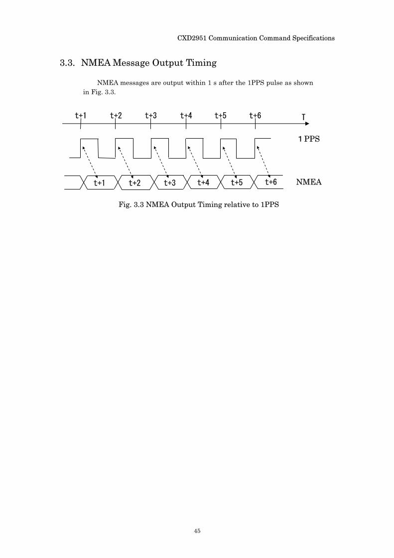
3.3. NMEA Message Output Timing
NMEA messages are output within 1 s after the 1PPS pulse as shown in Fig. 3.3.
t+1 t+2 t+3 t+4 t+5 t+6 T
1PPS
NMEA
Fig. 3.3 NMEA Output Timing relative to 1PPS
t+1 t+2 t+3 t+4 t+5 t+6
CXD2951 Communication Command Specifications
46
Chapter 4 Output Data Formats This chapter explains the CXD2951 output data formats.
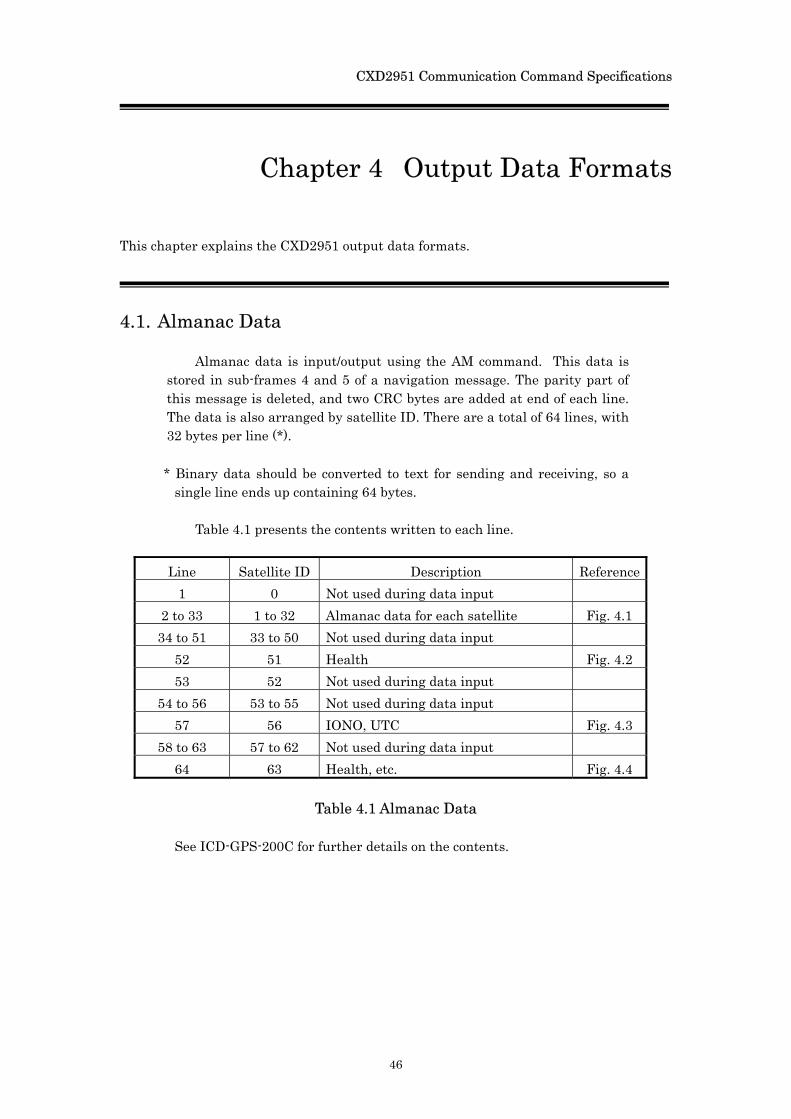
4.1. Almanac Data
Almanac data is input/output using the AM command. This data is stored in sub-frames 4 and 5 of a navigation message. The parity part of this message is deleted, and two CRC bytes are added at end of each line. The data is also arranged by satellite ID. There are a total of 64 lines, with 32 bytes per line (*).
* Binary data should be converted to text for sending and receiving, so a
single line ends up containing 64 bytes.
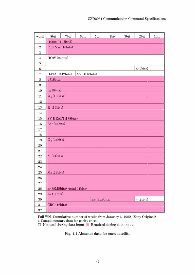
Table 4.1 presents the contents written to each line.
Line Satellite ID Description Reference 1 0 Not used during data input
2 to 33 1 to 32 Almanac data for each satellite Fig. 4.1 34 to 51 33 to 50 Not used during data input
52 51 Health Fig. 4.2 53 52 Not used during data input
54 to 56 53 to 55 Not used during data input 57 56 IONO, UTC Fig. 4.3
58 to 63 57 to 62 Not used during data input 64 63 Health, etc. Fig. 4.4
Table 4.1 Almanac Data
See ICD-GPS-200C for further details on the contents.
CXD2951 Communication Command Specifications
47
word 8bit 7bit 6bit 5bit 4bit 3bit 2bit 1bit 1 (10001011 fixed) 2 Full NW (16bits) 3 4 HOW (22bits) 5 6 t (2bits) 7 DATA ID (2bits) SV ID (6bits) 8 e (16bits) 9 10 toa (8bits)
11 δj (16bits) 12 13 Ω
・
(16bits) 14 15 SV HEALTH (8bits) 16 A1/2 (24bits) 17 18 19 Ω0 (24bits) 20 21 22 ω (24bits) 23 24 25 M0 (24bits) 26 27 28 af0 (8MSbits) -total 11bits- 29 af1 (11bits) 30 af0 (3LSbits) t (2bits) 31 CRC (16bits) 32
Full WN: Cumulative number of weeks from January 6, 1980. (Sony Original) t: Complementary data for parity check : Not used during data input : Required during data input
Fig. 4.1 Almanac data for each satellite
CXD2951 Communication Command Specifications
48
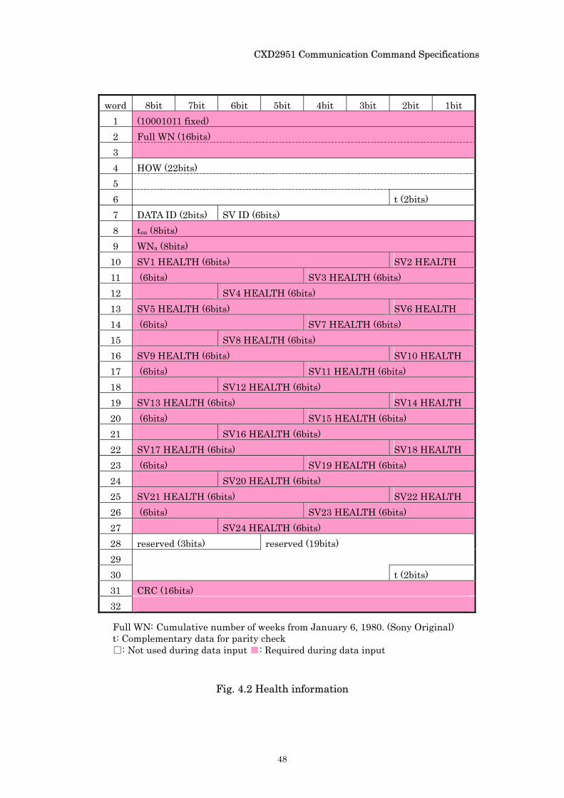
word 8bit 7bit 6bit 5bit 4bit 3bit 2bit 1bit 1 (10001011 fixed) 2 Full WN (16bits) 3 4 HOW (22bits) 5 6 t (2bits) 7 DATA ID (2bits) SV ID (6bits) 8 toa (8bits) 9 WNa (8bits) 10 SV1 HEALTH (6bits) SV2 HEALTH 11 (6bits) SV3 HEALTH (6bits) 12 SV4 HEALTH (6bits) 13 SV5 HEALTH (6bits) SV6 HEALTH 14 (6bits) SV7 HEALTH (6bits) 15 SV8 HEALTH (6bits) 16 SV9 HEALTH (6bits) SV10 HEALTH 17 (6bits) SV11 HEALTH (6bits) 18 SV12 HEALTH (6bits) 19 SV13 HEALTH (6bits) SV14 HEALTH 20 (6bits) SV15 HEALTH (6bits) 21 SV16 HEALTH (6bits) 22 SV17 HEALTH (6bits) SV18 HEALTH 23 (6bits) SV19 HEALTH (6bits) 24 SV20 HEALTH (6bits) 25 SV21 HEALTH (6bits) SV22 HEALTH 26 (6bits) SV23 HEALTH (6bits) 27 SV24 HEALTH (6bits) 28 reserved (3bits) reserved (19bits) 29 30 t (2bits) 31 CRC (16bits) 32
Fig. 4.2 Health information
Full WN: Cumulative number of weeks from January 6, 1980. (Sony Original) t: Complementary data for parity check : Not used during data input : Required during data input
CXD2951 Communication Command Specifications
49
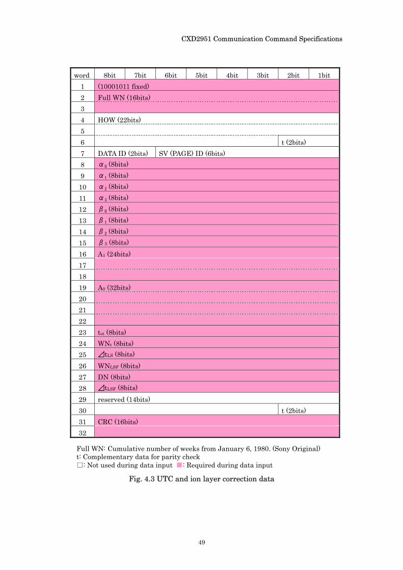
word 8bit 7bit 6bit 5bit 4bit 3bit 2bit 1bit 1 (10001011 fixed) 2 Full WN (16bits) 3 4 HOW (22bits) 5 6 t (2bits) 7 DATA ID (2bits) SV (PAGE) ID (6bits) 8 α0 (8bits) 9 α1 (8bits) 10 α2 (8bits) 11 α3 (8bits) 12 β0 (8bits) 13 β1 (8bits) 14 β2 (8bits) 15 β3 (8bits) 16 A1 (24bits) 17 18 19 A0 (32bits) 20 21 22 23 tot (8bits) 24 WNt (8bits) 25 ⊿tLS (8bits) 26 WNLSF (8bits) 27 DN (8bits) 28 ⊿tLSF (8bits) 29 reserved (14bits) 30 t (2bits) 31 CRC (16bits) 32
Fig. 4.3 UTC and ion layer correction data
Full WN: Cumulative number of weeks from January 6, 1980. (Sony Original) t: Complementary data for parity check : Not used during data input : Required during data input
CXD2951 Communication Command Specifications
50
word 8bit 7bit 6bit 5bit 4bit 3bit 2bit 1bit
1 (10001011 fixed)
2 Full WN (16bits)
3
4 HOW (22bits)
5
6 t (2bits)
7 DATA ID (2bits) SV (PAGE) ID (6bits)
8 SV1 A-SPOOF & SV CONFIG (4bits) SV2 A-SPOOF & SV CONFIG (4bits)
9 SV3 A-SPOOF & SV CONFIG (4bits) SV4 A-SPOOF & SV CONFIG (4bits)
10 SV5 A-SPOOF & SV CONFIG (4bits) SV6 A-SPOOF & SV CONFIG (4bits)
11 SV7 A-SPOOF & SV CONFIG (4bits) SV8 A-SPOOF & SV CONFIG (4bits)
12 SV9 A-SPOOF & SV CONFIG (4bits) SV10 A-SPOOF & SV CONFIG (4bits)
13 SV11 A-SPOOF & SV CONFIG (4bits) SV12 A-SPOOF & SV CONFIG (4bits)
14 SV13 A-SPOOF & SV CONFIG (4bits) SV14 A-SPOOF & SV CONFIG (4bits)
15 SV15 A-SPOOF & SV CONFIG (4bits) SV16 A-SPOOF & SV CONFIG (4bits)
16 SV17 A-SPOOF & SV CONFIG (4bits) SV18 A-SPOOF & SV CONFIG (4bits)
17 SV19 A-SPOOF & SV CONFIG (4bits) SV20 A-SPOOF & SV CONFIG (4bits)
18 SV21 A-SPOOF & SV CONFIG (4bits) SV22 A-SPOOF & SV CONFIG (4bits)
19 SV23 A-SPOOF & SV CONFIG (4bits) SV24 A-SPOOF & SV CONFIG (4bits)
20 SV25 A-SPOOF & SV CONFIG (4bits) SV26 A-SPOOF & SV CONFIG (4bits)
21 SV27 A-SPOOF & SV CONFIG (4bits) SV28 A-SPOOF & SV CONFIG (4bits)
22 SV29 A-SPOOF & SV CONFIG (4bits) SV30 A-SPOOF & SV CONFIG (4bits)
23 SV31 A-SPOOF & SV CONFIG (4bits) SV32 A-SPOOF & SV CONFIG (4bits)
24 reserved (2bits) SV25 HEALTH (6bits) v
25 SV26 HEALTH (6bits) SV27 HEALTH
26 SV28 HEALTH (6bits)
27 SV29 HEALTH (6bits)
28 SV30 HEALTH (6bits) SV31 HEALTH
29 (6bits) SV32 HEALTH (6bits)
30 reserved (4bits) t (2bits)
31 CRC (16bits)
32
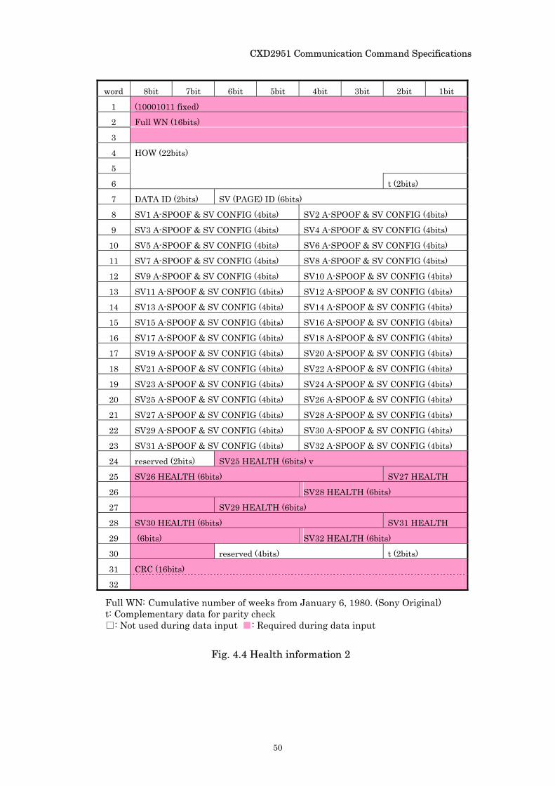
Fig. 4.4 Health information 2
Full WN: Cumulative number of weeks from January 6, 1980. (Sony Original) t: Complementary data for parity check : Not used during data input : Required during data input
CXD2951 Communication Command Specifications
51
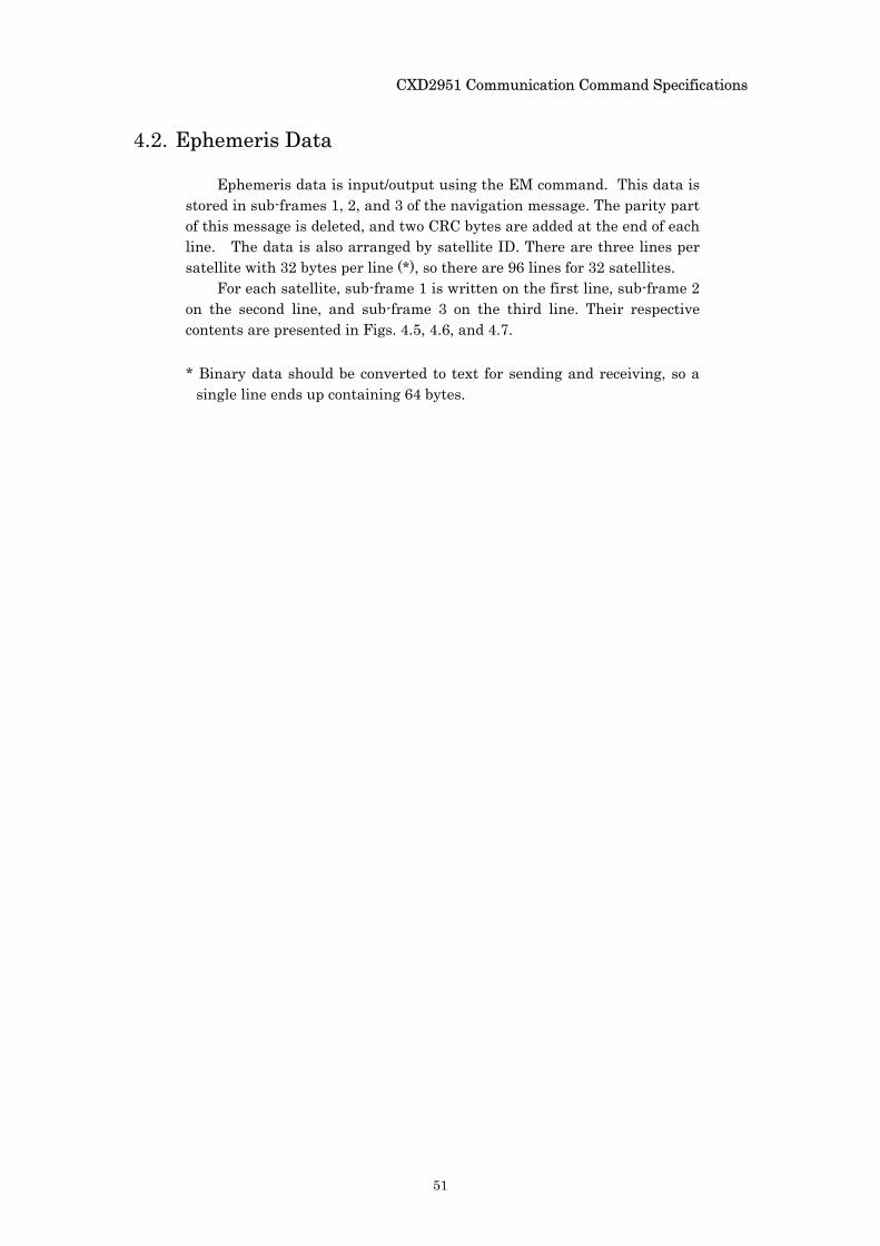
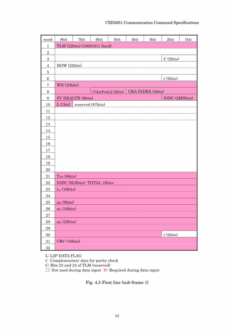
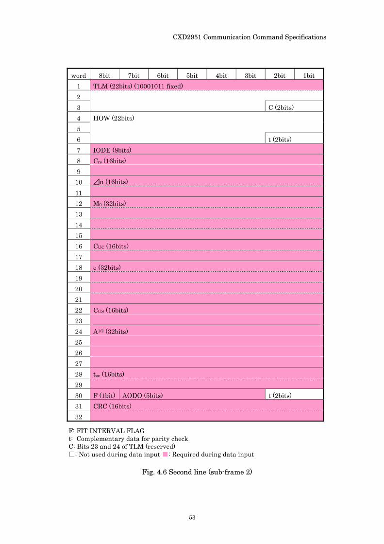
4.2. Ephemeris Data
Ephemeris data is input/output using the EM command. This data is stored in sub-frames 1, 2, and 3 of the navigation message. The parity part of this message is deleted, and two CRC bytes are added at the end of each line. The data is also arranged by satellite ID. There are three lines per satellite with 32 bytes per line (*), so there are 96 lines for 32 satellites.
For each satellite, sub-frame 1 is written on the first line, sub-frame 2 on the second line, and sub-frame 3 on the third line. Their respective contents are presented in Figs. 4.5, 4.6, and 4.7.
* Binary data should be converted to text for sending and receiving, so a single line ends up containing 64 bytes.
CXD2951 Communication Command Specifications
52
word 8bit 7bit 6bit 5bit 4bit 3bit 2bit 1bit
1 TLM (22bits) (10001011 fixed) 2 3 C (2bits) 4 HOW (22bits) 5 6 t (2bits) 7 WN (10bits) 8 C/AorPonL2 (2bits) URA INDEX (4bits) 9 SV HEALTH (6bits) IODC (2MSbits)
10 L (1bit) reserved (87bits) 11 12 13 14 15 16 17 18 19 20 21 TGD (8bits) 22 IODC (8LSbits) -TOTAL 10bits- 23 toc (16bits) 24 25 af2 (8bits) 26 af1 (16bits) 27 28 af0 (22bits) 29 30 t (2bits) 31 CRC (16bits) 32
L: L2P DATA FLAG t: Complementary data for parity check C: Bits 23 and 24 of TLM (reserved) : Not used during data input : Required during data input
Fig. 4.5 First line (sub-frame 1)
CXD2951 Communication Command Specifications
53
word 8bit 7bit 6bit 5bit 4bit 3bit 2bit 1bit 1 TLM (22bits) (10001011 fixed) 2 3 C (2bits) 4 HOW (22bits) 5 6 t (2bits) 7 IODE (8bits) 8 Crs (16bits) 9 10 ⊿n (16bits) 11 12 M0 (32bits) 13 14 15 16 CUC (16bits) 17 18 e (32bits) 19 20 21 22 CUS (16bits) 23 24 A1/2 (32bits) 25 26 27 28 toe (16bits) 29 30 F (1bit) AODO (5bits) t (2bits) 31 CRC (16bits) 32
F: FIT INTERVAL FLAG t: Complementary data for parity check C: Bits 23 and 24 of TLM (reserved) : Not used during data input : Required during data input
Fig. 4.6 Second line (sub-frame 2)
CXD2951 Communication Command Specifications
54
word 8bit 7bit 6bit 5bit 4bit 3bit 2bit 1bit 1 TLM (22bits) (10001011 fixed) 2 3 C (2bits) 4 HOW (22bits) 5 6 t (2bits) 7 Cic (16bits) 8 9 Ω0 (32bits)
10 11 12 13 Cis (16bits) 14 15 i0 (32bits) 16 17 18 19 Crc (16bits) 20 21 ω (32bits) 22 23 24 25 Ω
・
(24bits) 26 27 28 IODE (8bits) 29 IDOT (14bits) 30 t (2bits) 31 CRC (16bits) 32
Fig. 4.7 Third line (sub-frame 3)
t: Complementary data for parity check C: Bits 23 and 24 of TLM (reserved) : Not used during data input : Required during data input
CXD2951 Communication Command Specifications
55
CXD2951 Communication Command Specifications
Sony Corporation
Copyright © 2003,2004 Sony Corporation
![Protocol Specification [μ-blox GPS-MS1 and GPS-PS1] (GPS G1-X-00005)](https://static.fdocument.org/doc/165x107/552961054a795986158b46e0/protocol-specification-blox-gps-ms1-and-gps-ps1-gps-g1-x-00005.jpg)