DATASHEET Systems for evacuation systems System manual … · 5.1 Cenni sulla normativa IEC 60849...
37
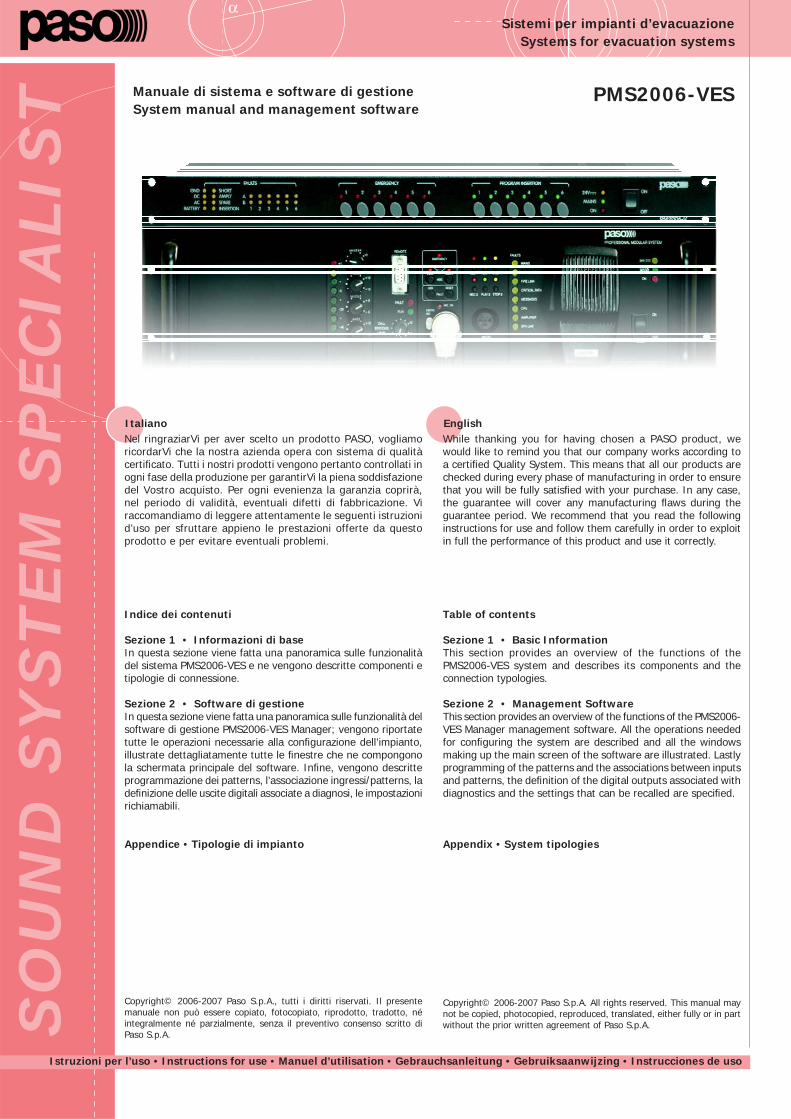
α SOUND SYSTEM SPECIALIST Istruzioni per l’uso • Instructions for use • Manuel d’utilisation • Gebrauchsanleitung • Gebruiksaanwijzing • Instrucciones de uso PMS2006-VES Sistemi per impianti d’evacuazione Systems for evacuation systems Italiano Nel ringraziarVi per aver scelto un prodotto PASO, vogliamo ricordarVi che la nostra azienda opera con sistema di qualità certificato. Tutti i nostri prodotti vengono pertanto controllati in ogni fase della produzione per garantirVi la piena soddisfazione del Vostro acquisto. Per ogni evenienza la garanzia coprirà, nel periodo di validità, eventuali difetti di fabbricazione. Vi raccomandiamo di leggere attentamente le seguenti istruzioni d’uso per sfruttare appieno le prestazioni offerte da questo prodotto e per evitare eventuali problemi. Manuale di sistema e software di gestione System manual and management software Indice dei contenuti Sezione 1 • Informazioni di base In questa sezione viene fatta una panoramica sulle funzionalità del sistema PMS2006-VES e ne vengono descritte componenti e tipologie di connessione. Sezione 2 • Software di gestione In questa sezione viene fatta una panoramica sulle funzionalità del software di gestione PMS2006-VES Manager; vengono riportate tutte le operazioni necessarie alla configurazione dell’impianto, illustrate dettagliatamente tutte le finestre che ne compongono la schermata principale del software. Infine, vengono descritte programmazione dei patterns, l’associazione ingressi/patterns, la definizione delle uscite digitali associate a diagnosi, le impostazioni richiamabili. Appendice • Tipologie di impianto Copyright© 2006-2007 Paso S.p.A., tutti i diritti riservati. Il presente manuale non può essere copiato, fotocopiato, riprodotto, tradotto, né integralmente né parzialmente, senza il preventivo consenso scritto di Paso S.p.A. English While thanking you for having chosen a PASO product, we would like to remind you that our company works according to a certified Quality System. This means that all our products are checked during every phase of manufacturing in order to ensure that you will be fully satisfied with your purchase. In any case, the guarantee will cover any manufacturing flaws during the guarantee period. We recommend that you read the following instructions for use and follow them carefully in order to exploit in full the performance of this product and use it correctly. Table of contents Sezione 1 • Basic Information This section provides an overview of the functions of the PMS2006-VES system and describes its components and the connection typologies. Sezione 2 • Management Software This section provides an overview of the functions of the PMS2006- VES Manager management software. All the operations needed for configuring the system are described and all the windows making up the main screen of the software are illustrated. Lastly programming of the patterns and the associations between inputs and patterns, the definition of the digital outputs associated with diagnostics and the settings that can be recalled are specified. Appendix • System tipologies Copyright© 2006-2007 Paso S.p.A. All rights reserved. This manual may not be copied, photocopied, reproduced, translated, either fully or in part without the prior written agreement of Paso S.p.A.
Transcript of DATASHEET Systems for evacuation systems System manual … · 5.1 Cenni sulla normativa IEC 60849...
DATASHEETα
SO
UN
D S
YS
TEM
SP
EC
IALIS
T
Istruzioni per l’uso • Instructions for use • Manuel d’utilisation • Gebrauchsanleitung • Gebruiksaanwijzing • Instrucciones de uso
PMS2006-VES
Sistemi per impianti d’evacuazioneSystems for evacuation systems
ItalianoNel ringraziarVi per aver scelto un prodotto PASO, vogliamo ricordarVi che la nostra azienda opera con sistema di qualità certifi cato. Tutti i nostri prodotti vengono pertanto controllati in ogni fase della produzione per garantirVi la piena soddisfazione del Vostro acquisto. Per ogni evenienza la garanzia coprirà, nel periodo di validità, eventuali difetti di fabbricazione. Vi raccomandiamo di leggere attentamente le seguenti istruzioni d’uso per sfruttare appieno le prestazioni offerte da questo prodotto e per evitare eventuali problemi.
Manuale di sistema e software di gestioneSystem manual and management software
Indice dei contenuti
Sezione 1 • Informazioni di baseIn questa sezione viene fatta una panoramica sulle funzionalità del sistema PMS2006-VES e ne vengono descritte componenti e tipologie di connessione.
Sezione 2 • Software di gestioneIn questa sezione viene fatta una panoramica sulle funzionalità del software di gestione PMS2006-VES Manager; vengono riportate tutte le operazioni necessarie alla confi gurazione dell’impianto, illustrate dettagliatamente tutte le fi nestre che ne compongono la schermata principale del software. Infi ne, vengono descritte programmazione dei patterns, l’associazione ingressi/patterns, la defi nizione delle uscite digitali associate a diagnosi, le impostazioni richiamabili.
Appendice • Tipologie di impianto
Copyright© 2006-2007 Paso S.p.A., tutti i diritti riservati. Il presente manuale non può essere copiato, fotocopiato, riprodotto, tradotto, né integralmente né parzialmente, senza il preventivo consenso scritto di Paso S.p.A.
EnglishWhile thanking you for having chosen a PASO product, we would like to remind you that our company works according to a certifi ed Quality System. This means that all our products are checked during every phase of manufacturing in order to ensure that you will be fully satisfi ed with your purchase. In any case, the guarantee will cover any manufacturing fl aws during the guarantee period. We recommend that you read the following instructions for use and follow them carefully in order to exploit in full the performance of this product and use it correctly.
Table of contents
Sezione 1 • Basic InformationThis section provides an overview of the functions of the PMS2006-VES system and describes its components and the connection typologies.
Sezione 2 • Management SoftwareThis section provides an overview of the functions of the PMS2006-VES Manager management software. All the operations needed for confi guring the system are described and all the windows making up the main screen of the software are illustrated. Lastly programming of the patterns and the associations between inputs and patterns, the defi nition of the digital outputs associated with diagnostics and the settings that can be recalled are specifi ed.
Appendix • System tipologies
Copyright© 2006-2007 Paso S.p.A. All rights reserved. This manual may not be copied, photocopied, reproduced, translated, either fully or in part without the prior written agreement of Paso S.p.A.
DATASHEETα
2
SEZIONE 1 • INFORMAZIONI DI BASE
1. Generalità sul Sistema ......................................................... 3
2. Descrizione delle parti ........................................................ 3 2.1 Unità di gestione segnale ................................................... 3 2.2 Unità di controllo e distribuzione 6 linee .............................. 4
3. Connessioni ......................................................................... 4
4. Tipologie di impianto ........................................................... 54.1 Impianto con amplifi catore singolo ............................................ 54.2 Impianto con due amplifi catori dedicati ...................................... 54.3 Impianto con due amplifi catori dedicati + riserva ....................... 54.4 Espansione delle zone d’ascolto ................................................. 5
SEZIONE 2 • SOFTWARE DI GESTIONE
1. Generalità sul PMS2006 Manager ....................................... 6
2. Operazioni preliminari ......................................................... 6 2.1 Requisiti minimi di sistema ................................................. 6 2.2 Collegamento al sistema .................................................... 6 2.3 Installazione del software .................................................. 6
3. Messa in servizio .................................................................. 7 3.1 Inizializzazione dell’impianto .............................................. 7 3.2 Confi gurazione del sistema ................................................ 8
4. Descrizione della schermata principale ............................ 12 4.1 Finestra < Faults > ......................................................... 13 4.2 Finestra < PM2006-V > ................................................... 15 4.3 Finestra < PM131/6 Consoles > ....................................... 16 4.4 Finestra < Zones > ......................................................... 17 4.5 Barra < Automonitoring > ............................................... 18 4.6 Menu < Options > .......................................................... 19 4.7 Menu < More... > ........................................................... 19
5. Programmazione ................................................................ 205.1 Cenni sulla normativa IEC 60849 (CEI 100-55) ......................... 205.2 Il sistema realizzato da Paso ................................................... 215.3 Programmazione del sistema ................................................... 24
APPENDICE ................................................................................. 33
SECTION 1 • BASIC INFORMATION
1. General Information about the System .............................. 3
2. Description of the parts ...................................................... 3 2.1 Signal-management unit .................................................... 3 2.2 Control unit and distribution to 6 lines ................................ 4
3. Connections .......................................................................... 4
4. System Tipologies ................................................................ 54.1 Single amplifi er ........................................................................ 54.2 Two dedicated amplifers ........................................................... 54.3 Two dedicated amplifers + stand-by .......................................... 54.4 Expansion of listening zones ..................................................... 5
SECTION 2 • MANAGEMENT SOFTWARE
1. General information about PMS2006-VES Manager ........... 6
2. Preliminary operations......................................................... 6 2.1 Minimum system requirements ........................................... 6 2.2 Connection to the system .................................................. 6 2.3 Installing the software ....................................................... 6
3. Commissioning ..................................................................... 7 3.1 Initialising the system ........................................................ 7 3.2 Confi guration of the system ............................................... 8
4. Description of the main screen page ................................. 12 4.1 < Faults > Window ......................................................... 13 4.2 < PM2006-V > Window ................................................... 15 4.3 < PM131/6 Consoles > Window ....................................... 16 4.4 < Zones > Window ......................................................... 17 4.5 < Automonitoring > Bar .................................................. 18 4.6 < Options > Menu .......................................................... 19 4.7 < More... > Menu ........................................................... 19
5. Programming ...................................................................... 205.1 Outline of IEC standard 60849 (CEI 100 55) ............................ 205.2 The system designed by Paso ................................................. 215.3 Programming the system ........................................................ 24
APPENDIX ................................................................................... 33
DATASHEET PMS2006-VES
3
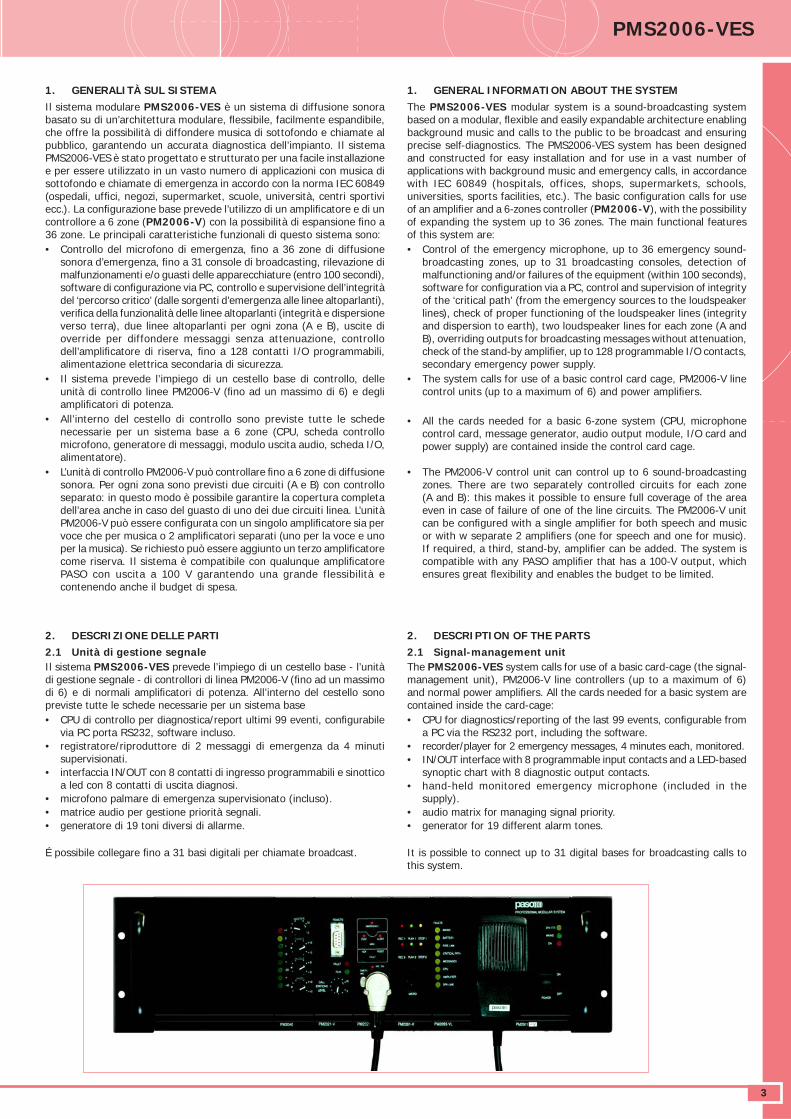
1. GENERALITÀ SUL SISTEMAIl sistema modulare PMS2006-VES è un sistema di diffusione sonora basato su di un’architettura modulare, fl essibile, facilmente espandibile, che offre la possibilità di diffondere musica di sottofondo e chiamate al pubblico, garantendo un accurata diagnostica dell’impianto. Il sistema PMS2006-VES è stato progettato e strutturato per una facile installazione e per essere utilizzato in un vasto numero di applicazioni con musica di sottofondo e chiamate di emergenza in accordo con la norma IEC 60849 (ospedali, uffi ci, negozi, supermarket, scuole, università, centri sportivi ecc.). La confi gurazione base prevede l’utilizzo di un amplifi catore e di un controllore a 6 zone (PM2006-V) con la possibilità di espansione fi no a 36 zone. Le principali caratteristiche funzionali di questo sistema sono:• Controllo del microfono di emergenza, fi no a 36 zone di diffusione
sonora d’emergenza, fi no a 31 console di broadcasting, rilevazione di malfunzionamenti e/o guasti delle apparecchiature (entro 100 secondi), software di confi gurazione via PC, controllo e supervisione dell’integrità del ‘percorso critico’ (dalle sorgenti d’emergenza alle linee altoparlanti), verifi ca della funzionalità delle linee altoparlanti (integrità e dispersione verso terra), due linee altoparlanti per ogni zona (A e B), uscite di override per diffondere messaggi senza attenuazione, controllo dell’amplifi catore di riserva, fi no a 128 contatti I/O programmabili, alimentazione elettrica secondaria di sicurezza.
• Il sistema prevede l’impiego di un cestello base di controllo, delle unità di controllo linee PM2006-V (fi no ad un massimo di 6) e degli amplifi catori di potenza.
• All’interno del cestello di controllo sono previste tutte le schede necessarie per un sistema base a 6 zone (CPU, scheda controllo microfono, generatore di messaggi, modulo uscita audio, scheda I/O, alimentatore).
• L’unità di controllo PM2006-V può controllare fi no a 6 zone di diffusione sonora. Per ogni zona sono previsti due circuiti (A e B) con controllo separato: in questo modo è possibile garantire la copertura completa dell’area anche in caso del guasto di uno dei due circuiti linea. L’unità PM2006-V può essere confi gurata con un singolo amplifi catore sia per voce che per musica o 2 amplifi catori separati (uno per la voce e uno per la musica). Se richiesto può essere aggiunto un terzo amplifi catore come riserva. Il sistema è compatibile con qualunque amplifi catore PASO con uscita a 100 V garantendo una grande flessibilità e contenendo anche il budget di spesa.
2. DESCRIZIONE DELLE PARTI2.1 Unità di gestione segnaleIl sistema PMS2006-VES prevede l’impiego di un cestello base - l’unità di gestione segnale - di controllori di linea PM2006-V (fi no ad un massimo di 6) e di normali amplifi catori di potenza. All’interno del cestello sono previste tutte le schede necessarie per un sistema base• CPU di controllo per diagnostica/report ultimi 99 eventi, confi gurabile
via PC porta RS232, software incluso. • registratore/riproduttore di 2 messaggi di emergenza da 4 minuti
supervisionati.• interfaccia IN/OUT con 8 contatti di ingresso programmabili e sinottico
a led con 8 contatti di uscita diagnosi. • microfono palmare di emergenza supervisionato (incluso).• matrice audio per gestione priorità segnali.• generatore di 19 toni diversi di allarme.
É possibile collegare fi no a 31 basi digitali per chiamate broadcast.
1. GENERAL INFORMATION ABOUT THE SYSTEMThe PMS2006-VES modular system is a sound-broadcasting system based on a modular, fl exible and easily expandable architecture enabling background music and calls to the public to be broadcast and ensuring precise self-diagnostics. The PMS2006-VES system has been designed and constructed for easy installation and for use in a vast number of applications with background music and emergency calls, in accordance with IEC 60849 (hospitals, offices, shops, supermarkets, schools, universities, sports facilities, etc.). The basic confi guration calls for use of an amplifi er and a 6-zones controller (PM2006-V), with the possibility of expanding the system up to 36 zones. The main functional features of this system are:• Control of the emergency microphone, up to 36 emergency sound-
broadcasting zones, up to 31 broadcasting consoles, detection of malfunctioning and/or failures of the equipment (within 100 seconds), software for confi guration via a PC, control and supervision of integrity of the ‘critical path’ (from the emergency sources to the loudspeaker lines), check of proper functioning of the loudspeaker lines (integrity and dispersion to earth), two loudspeaker lines for each zone (A and B), overriding outputs for broadcasting messages without attenuation, check of the stand-by amplifi er, up to 128 programmable I/O contacts, secondary emergency power supply.
• The system calls for use of a basic control card cage, PM2006-V line control units (up to a maximum of 6) and power amplifi ers.
• All the cards needed for a basic 6-zone system (CPU, microphone control card, message generator, audio output module, I/O card and power supply) are contained inside the control card cage.
• The PM2006-V control unit can control up to 6 sound-broadcasting zones. There are two separately controlled circuits for each zone (A and B): this makes it possible to ensure full coverage of the area even in case of failure of one of the line circuits. The PM2006-V unit can be confi gured with a single amplifi er for both speech and music or with w separate 2 amplifi ers (one for speech and one for music). If required, a third, stand-by, amplifi er can be added. The system is compatible with any PASO amplifi er that has a 100-V output, which ensures great fl exibility and enables the budget to be limited.
2. DESCRIPTION OF THE PARTS2.1 Signal-management unitThe PMS2006-VES system calls for use of a basic card-cage (the signal-management unit), PM2006-V line controllers (up to a maximum of 6) and normal power amplifi ers. All the cards needed for a basic system are contained inside the card-cage:• CPU for diagnostics/reporting of the last 99 events, confi gurable from
a PC via the RS232 port, including the software. • recorder/player for 2 emergency messages, 4 minutes each, monitored.• IN/OUT interface with 8 programmable input contacts and a LED-based
synoptic chart with 8 diagnostic output contacts. • hand-held monitored emergency microphone (included in the
supply).• audio matrix for managing signal priority. • generator for 19 different alarm tones.
It is possible to connect up to 31 digital bases for broadcasting calls to this system.
DATASHEETα
4
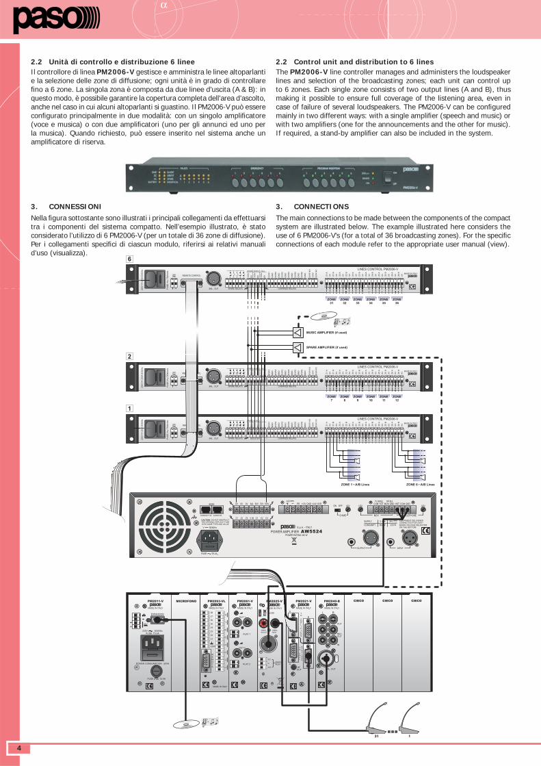
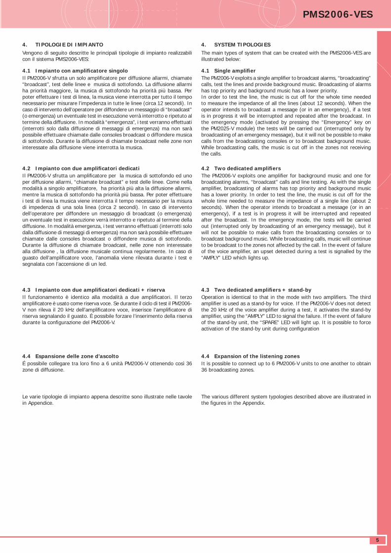
2.2 Unità di controllo e distribuzione 6 lineeIl controllore di linea PM2006-V gestisce e amministra le linee altoparlanti e la selezione delle zone di diffusione; ogni unità è in grado di controllare fi no a 6 zone. La singola zona è composta da due linee d’uscita (A & B): in questo modo, è possibile garantire la copertura completa dell’area d’ascolto, anche nel caso in cui alcuni altoparlanti si guastino. Il PM2006-V può essere confi gurato principalmente in due modalità: con un singolo amplifi catore (voce e musica) o con due amplifi catori (uno per gli annunci ed uno per la musica). Quando richiesto, può essere inserito nel sistema anche un amplifi catore di riserva.
3. CONNESSIONINella fi gura sottostante sono illustrati i principali collegamenti da effettuarsi tra i componenti del sistema compatto. Nell’esempio illustrato, è stato considerato l’utilizzo di 6 PM2006-V (per un totale di 36 zone di diffusione). Per i collegamenti specifi ci di ciascun modulo, riferirsi ai relativi manuali d’uso (visualizza).
2.2 Control unit and distribution to 6 linesThe PM2006-V line controller manages and administers the loudspeaker lines and selection of the broadcasting zones; each unit can control up to 6 zones. Each single zone consists of two output lines (A and B), thus making it possible to ensure full coverage of the listening area, even in case of failure of several loudspeakers. The PM2006-V can be confi gured mainly in two different ways: with a single amplifi er (speech and music) or with two amplifi ers (one for the announcements and the other for music). If required, a stand-by amplifi er can also be included in the system.
3. CONNECTIONSThe main connections to be made between the components of the compact system are illustrated below. The example illustrated here considers the use of 6 PM2006-V’s (for a total of 36 broadcasting zones). For the specifi c connections of each module refer to the appropriate user manual (view).
MADE IN ITALY
23
0V
25
VA
50
/60
Hz
FU
SE
T5
00
mA
L
REMOTE CONTROL24V
BAL. OUT SPARE RELAYS
0V
100V
100V
0V
100V
0V
MUSICSPARE CALL
OVERRIDE RELAYS
GN
D
OV
R1
OV
R2
GN
D
GN
D
OV
R3
OV
R4
GN
D
GN
D
OV
R5
OV
R6
GN
D
+24V
OV
RN
O
OV
RN
C
OUTPUT ZONES 100V
0V
Z1
A
Z1
B
0V
0V
Z2
A
Z2
B
0V
0V
Z4
A
Z4
B
0V
0V
Z3
A
0V
0V
Z5
A
Z5
B
0V
0V
Z6
A
Z6
B
0V
Z3
B
LINES CONTROL PM2006-V
EXPANSION
230V 50/60Hz
FUSE T0.5A
+24V
POWER CONSUMPTION 50VA
FUSE T2.5A
MADE IN ITALY
PM2061-V
OUT 1
PLAY 1
OUT 2
PLAY 2EMERG.RELAY
N.C.
C
N.O.
UNBAL.PA OUT
BUZZER
UNBAL.PA IN
MADE IN ITALY
PM2025-V
MADE IN ITALY
PM2021-V
T
O
A
M
P
L
I
F
I
E
R
S
T
O
C
A
L
L
S
T
A
T
I
O
N
S
B
A
BOUT
BF
A
MADE IN ITALY
PM2040-B
L R
OUT
REC.
OUT
IN
BAL. OUT
MICROFONO
I8
I78
7
6
5
4
3
2
1
R
E
M
O
T
E
MADE IN ITALY
+24V
I6
I5
I4
I3
I2
I1
CIECO CIECO CIECO
MADE IN ITALY
PM2093-VL
MADE IN ITALY
PM2011-V
MADE IN ITALY
23
0V
25
VA
50
/60
Hz
FU
SE
T5
00
mA
L
REMOTE CONTROL24V
BAL. OUT SPARE RELAYS BOOSTER IN
0V
100V
100V
0V
100V
0V
MUSICSPARE CALL
OVERRIDE RELAYS
GN
D
OV
R1
OV
R2
GN
D
GN
D
OV
R3
OV
R4
GN
D
GN
D
OV
R5
OV
R6
GN
D
+24V
OV
RN
O
OV
RN
C
OUTPUT ZONES 100V
0V
Z1
A
Z1
B
0V
0V
Z2
A
Z2
B
0V
0V
Z4
A
Z4
B
0V
0V
Z3
A
0V
0V
Z5
A
Z5
B
0V
0V
Z6
A
Z6
B
0V
Z3
B
LINES CONTROL PM2006-V
V 50/60Hz
EQUIPMENT DELIVERED
CONNECTED FOR 230V~.
MAINS VOLTAGE SELECTOR
ON THE BOTTOM
24V
C3C2C1V INZ3Z2Z1
100V70V50V8Ω0V0V0V OVR+24VGND+12VPR GNDCOMHOTGNDMONHOTCOM1V 600Ω 1W 8Ω
MOH TELEPHONE
LEV. LEV.LEV.
CHIME
ON OFF
S.p.A. - ITALY
POWER AMPLIFIER AW5524
CAUTION: DO NOT OBSTRUCT
THE OPENING. REPLACE FUSE
WITH SAME TYPE AND VALUE
POWER RATING 240 W
600 W 320 WCONSUMPT.
SUPPLY V 24V
CONTACT IN AUDIO IN
BASE
FUSE T6.3AL
INPUTOUTPUT
ZONE 1 • A/B Lines ZONE 6 • A/B Lines
MADE IN ITALY
23
0V
25
VA
50
/60
Hz
FU
SE
T5
00
mA
L
REMOTE CONTROL24V
BAL. OUT SPARE RELAYS
0V
100V
100V
0V
100V
0V
MUSICSPARE CALL
OVERRIDE RELAYS
GN
D
OV
R1
OV
R2
GN
D
GN
D
OV
R3
OV
R4
GN
D
GN
D
OV
R5
OV
R6
GN
D
+24V
OV
RN
O
OV
RN
C
0V
Z1
A
Z1
B
0V
0V
Z2
A
Z2
B
0V
0V
Z4
A
Z4
B
0V
0V
Z3
A
0V
0V
Z5
A
Z5
B
0V
0V
Z6
A
Z6
B
0V
Z3
B
LINES CONTROL PM2006-V
ZONE7
ZONE8
ZONE9
ZONE10
ZONE11
ZONE12
OUTPUT ZONES 100V
ZONE31
ZONE32
ZONE33
ZONE34
ZONE35
ZONE36
1
2
6
SPARE AMPLIFIER (if used)
MUSIC AMPLIFIER (if used)
DATASHEET PMS2006-VES
5
4. TIPOLOGIE DI IMPIANTOVengono di seguito descritte le principali tipologie di impianto realizzabili con il sistema PMS2006-VES:
4.1 Impianto con amplifi catore singolo Il PM2006-V sfrutta un solo amplifi catore per diffusione allarmi, chiamate “broadcast”, test delle linee e musica di sottofondo. La diffusione allarmi ha priorità maggiore, la musica di sottofondo ha priorità più bassa. Per poter effettuare i test di linea, la musica viene interrotta per tutto il tempo necessario per misurare l’impedenza in tutte le linee (circa 12 secondi). In caso di intervento dell’operatore per diffondere un messaggio di “broadcast” (o emergenza) un eventuale test in esecuzione verrà interrotto e ripetuto al termine della diffusione. In modalità “emergenza”, i test verranno effettuati (interrotti solo dalla diffusione di messaggi di emergenza) ma non sarà possibile effettuare chiamate dalle consoles broadcast o diffondere musica di sottofondo. Durante la diffusione di chiamate broadcast nelle zone non interessate alla diffusione viene interrotta la musica.
4.2 Impianto con due amplifi catori dedicati Il PM2006-V sfrutta un amplifi catore per la musica di sottofondo ed uno per diffusione allarmi, “chiamate broadcast” e test delle linee. Come nella modalità a singolo amplifi catore, ha priorità più alta la diffusione allarmi, mentre la musica di sottofondo ha priorità più bassa. Per poter effettuare i test di linea la musica viene interrotta il tempo necessario per la misura di impedenza di una sola linea (circa 2 secondi). In caso di intervento dell’operatore per diffondere un messaggio di broadcast (o emergenza) un eventuale test in esecuzione verrà interrotto e ripetuto al termine della diffusione. In modalità emergenza, i test verranno effettuati (interrotti solo dalla diffusione di messaggi di emergenza) ma non sarà possibile effettuare chiamate dalle consoles broadcast o diffondere musica di sottofondo. Durante la diffusione di chiamate broadcast, nelle zone non interessate alla diffusione , la diffusione musicale continua regolarmente. In caso di guasto dell’amplifi catore voce, l’anomalia viene rilevata durante i test e segnalata con l’accensione di un led.
4.3 Impianto con due amplifi catori dedicati + riservaIl funzionamento è identico alla modalità a due amplifi catori. Il terzo amplifi catore è usato come riserva voce. Se durante il ciclo di test il PM2006-V non rileva il 20 kHz dell’amplifi catore voce, inserisce l’amplifi catore di riserva segnalando il guasto. È possibile forzare l’inserimento della riserva durante la confi gurazione del PM2006-V.
4.4 Espansione delle zone d’ascoltoÉ possibile collegare tra loro fi no a 6 unità PM2006-V ottenendo così 36 zone di diffusione.
Le varie tipologie di impianto appena descritte sono illustrate nelle tavole in Appendice.
4. SYSTEM TIPOLOGIESThe main types of system that can be created with the PMS2006-VES are illustrated below:
4.1 Single amplifi er The PM2006-V exploits a single amplifi er to broadcast alarms, “broadcasting” calls, test the lines and provide background music. Broadcasting of alarms has top priority and background music has a lower priority.In order to test the line, the music is cut off for the whole time needed to measure the impedance of all the lines (about 12 seconds). When the operator intends to broadcast a message (or in an emergency), if a test is in progress it will be interrupted and repeated after the broadcast. In the emergency mode (activated by pressing the “Emergency” key on the PM2025-V module) the tests will be carried out (interrupted only by broadcasting of an emergency message), but it will not be possible to make calls from the broadcasting consoles or to broadcast background music. While broadcasting calls, the music is cut off in the zones not receiving the calls.
4.2 Two dedicated amplifi ers The PM2006-V exploits one amplifi er for background music and one for broadcasting alarms, “broadcast” calls and line testing. As with the single amplifi er, broadcasting of alarms has top priority and background music has a lower priority. In order to test the line, the music is cut off for the whole time needed to measure the impedance of a single line (about 2 seconds). When the operator intends to broadcast a message (or in an emergency), if a test is in progress it will be interrupted and repeated after the broadcast. In the emergency mode, the tests will be carried out (interrupted only by broadcasting of an emergency message), but it will not be possible to make calls from the broadcasting consoles or to broadcast background music. While broadcasting calls, music will continue to be broadcast to the zones not affected by the call. In the event of failure of the voice amplifi er, an upset detected during a test is signalled by the “AMPLY” LED which lights up.
4.3 Two dedicated amplifi ers + stand-byOperation is identical to that in the mode with two amplifi ers. The third amplifi er is used as a stand-by for voice. If the PM2006-V does not detect the 20 kHz of the voice amplifi er during a test, it activates the stand-by amplifi er, using the “AMPLY” LED to signal the failure. If the event of failure of the stand-by unit, the “SPARE” LED will light up. It is possible to force activation of the stand-by unit during confi guration
4.4 Expansion of the listening zonesIt is possible to connect up to 6 PM2006-V units to one another to obtain 36 broadcasting zones.
The various different system typologies described above are illustrated in the fi gures in the Appendix.
DATASHEETα
6
SEZIONE 2 • SOFTWARE DI GESTIONE
1. GENERALITÀ SUL PMS2006-VES MANAGERIl PMS2006-VES è un sistema in grado di rispondere ai requisiti richiesti dalla normativa IEC 60849 riguardante i sistemi per la gestione delle emergenze e dell’evacuazione. I sistemi che rispondono a questi requisiti sono comunemente riconosciuti con la sigla VES, Voice Evacuation System. Il sistema realizzato da PASO si compone di una serie di moduli ed apparecchiature, appositamente realizzate per rispondere ai requisiti imposti della normativa; tutte le attività sono coordinate da una unità centrale CPU nella quale si trova il fi le di confi gurazione contenente le informazioni necessarie per poter gestire autonomamente le attività dell’intero sistema.Il software di gestione PMS2006-VES Manager, sviluppato per eseguire la messa in funzione del sistema mediante l’ausilio di procedure automatizzate guidate, consente inoltre di programmare il piano d’evacuazione, monitorare eventuali guasti ed attività, effettuare la telemetria degli amplifi catori e delle consoles. Il collegamento tra il PC ed il PMS2006-VES avviene attraverso la connessione diretta tra il modulo CPU e la porta seriale RS232 del PC.Il software, oltre alla prima fase di start-up, alla programmazione delle procedure d’emergenze ed al monitoraggio dell’impianto, consente la visualizzazione del ‘logging’ delle attività legate alle emergenze ed ai guasti avvenuti. Nel logging sono riportate informazioni relative al tipo di guasto/attività avvenuto/e con ora e data dell’evento. Tali informazioni oltre che ad essere visualizzate possono anche essere salvate in un fi le formato testo (*.txt) in modo da renderle disponibili per qualsiasi consultazione successiva.
2. OPERAZIONI PRELIMINARI2.1 Requisiti minimi di sistemaPer una corretta esecuzione del software PMS2006-VES Manager, aver cura che le caratteristiche del pc soddisfi no le seguenti specifi che:• Processore Intel Pentium o equivalente.• OS: Windows ‘98, Windows 2000, Windows Me, Windows XP.• 20 MB di spazio disponibile su disco rigido.• Unità CD-ROM.• Porta seriale RS232.
2.2 Collegamento al sistemaAssicurarsi che la porta seriale RS232 del PC sia collegata tramite il cavo CV35 (o cavo standard reperibile in commercio) al modulo CPU di un Sistema PMS2006-VES completamente funzionante ed alimentato (*).
2.3 Installazione del software1) Inserire il CD nell’unità CD-ROM del computer.2) Seguire le istruzioni che appariranno sullo schermo.
Nel caso l’installazione non dovesse partire automaticamente, operare come segue:1) Premere ‘Start’ > ‘Esegui’ sul menu di avvio;2) Selezionare il fi le ‘Setup.exe’ e premere ‘OK’;3) Seguire le istruzioni che appariranno sullo schermo per concludere
l’installazione.
Al termine della procedura guidata, verrà creata un’icona sul desktop.
(*) per l’installazione, la confi gurazione e la messa in opera di un impianto, riferirsi alla documentazione relativa.
SECTION 2 • MANAGEMENT SOFTWARE
1. GENERAL INFORMATION ABOUT PMS2006-VES MANAGERIl PMS2006-VES è un sistema in grado di rispondere ai requisiti richiesti dalla normativa IEC 60849 riguardante i sistemi per la gestione delle emergenze e dell’evacuazione. I sistemi che rispondono a questi requisiti sono comunemente riconosciuti con la sigla VES, Voice Evacuation System. Il sistema realizzato da PASO si compone di una serie di moduli ed apparecchiature, appositamente realizzate per rispondere ai requisiti imposti della normativa; tutte le attività sono coordinate da una unità centrale CPU nella quale si trova il fi le di confi gurazione contenente le informazioni necessarie per poter gestire autonomamente le attività dell’intero sistema.Il software di gestione PMS2006-VES Manager, sviluppato per eseguire la messa in funzione del sistema mediante l’ausilio di procedure automatizzate guidate, consente inoltre di programmare il piano d’evacuazione, monitorare eventuali guasti ed attività, effettuare la telemetria degli amplifi catori e delle consoles. Il collegamento tra il PC ed il PMS2006-VES avviene attraverso la connessione diretta tra il modulo CPU e la porta seriale RS232 del PC.Il software, oltre alla prima fase di start-up, alla programmazione delle procedure d’emergenze ed al monitoraggio dell’impianto, consente la visualizzazione del ‘logging’ delle attività legate alle emergenze ed ai guasti avvenuti. Nel logging sono riportate informazioni relative al tipo di guasto/attività avvenuto/e con ora e data dell’evento. Tali informazioni oltre che ad essere visualizzate possono anche essere salvate in un fi le formato testo (*.txt) in modo da renderle disponibili per qualsiasi consultazione successiva.
2. PRELIMINARY OPERATIONS2.1 Minimum system requirementsTo ensure that the PMS2006-VES Manager software will run properly, make sure that the PC meets the following specifi cations:• Intel Pentium or equivalent processor.• OS: Windows ‘98, Windows 2000, Windows Me, Windows XP.• 20 MB of space available on the hard disk.• CD-ROM drive.• RS232 serial port.
2.2 Connection to the systemMake sure that the RS232 serial port of the PC is connected via the CV35 cable (or standard cable available on the market) to the PM2021-V module CPU of a fully operational and properly powered PMS2006-VES System (*).
2.3 Installing the software1) Insert the CD into the CD-ROM drive of the computer.2) Follow the instructions that appear on the screen.
If the set-up routine does not start automatically. Proceed as follows:
1) Press ‘Start’ > ‘Run’ from the start-up menu;2) Select the ‘Setup.exe’ fi le and press ‘OK’;3) Follow the instructions appearing on the screen to complete the set-
up.
Upon completion of the guided procedure, an icon will be created on your desktop.
(*) For installing, confi guring and commissioning a system, refer to the relevant documentation.
DATASHEET PMS2006-VES
7
(1) Se si verifi cano degli errori nella comunicazione vi sono una serie di cause possibili: collegamento seriale RS232 non corretto (o cavo non standard), sistema non è completamento acceso (l’alimentatore del cestello deve essere acceso) oppure la selezione della porta seriale non è corretta. Per cambiare la porta seriale, cliccare su Options > Serial port > e selezionare la porta seriale utilizzata. Il programma, a causa di questa operazione, verrà riavviato.
(2) La schermata <System Clock> appare in automatico quando nel PMS2006-VES non è presente un fi le di confi gurazione.
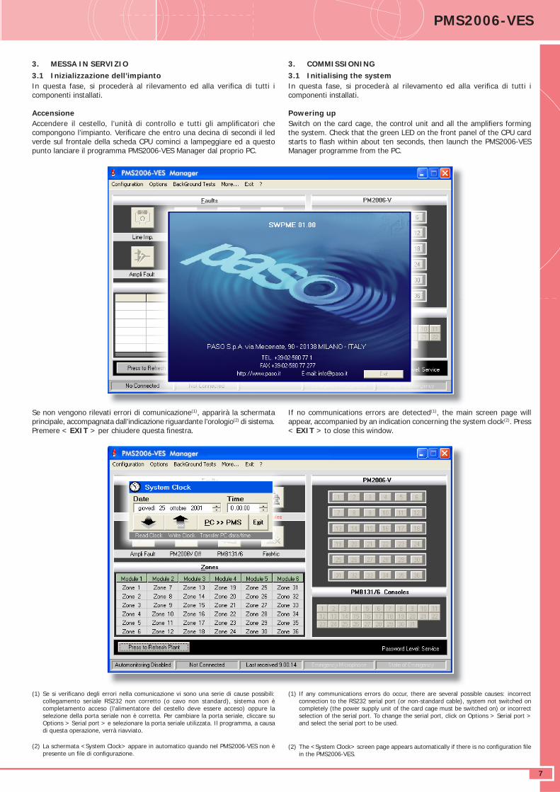
3. MESSA IN SERVIZIO3.1 Inizializzazione dell’impianto In questa fase, si procederà al rilevamento ed alla verifi ca di tutti i componenti installati.
AccensioneAccendere il cestello, l’unità di controllo e tutti gli amplifi catori che compongono l’impianto. Verifi care che entro una decina di secondi il led verde sul frontale della scheda CPU cominci a lampeggiare ed a questo punto lanciare il programma PMS2006-VES Manager dal proprio PC.
Se non vengono rilevati errori di comunicazione(1), apparirà la schermata principale, accompagnata dall’indicazione riguardante l’orologio(2) di sistema. Premere < EXIT > per chiudere questa fi nestra.
3. COMMISSIONING3.1 Initialising the system In questa fase, si procederà al rilevamento ed alla verifi ca di tutti i componenti installati.
Powering upSwitch on the card cage, the control unit and all the amplifi ers forming the system. Check that the green LED on the front panel of the CPU card starts to fl ash within about ten seconds, then launch the PMS2006-VES Manager programme from the PC.
If no communications errors are detected(1), the main screen page will appear, accompanied by an indication concerning the system clock(2). Press < EXIT > to close this window.
(1) If any communications errors do occur, there are several possible causes: incorrect connection to the RS232 serial port (or non-standard cable), system not switched on completely (the power supply unit of the card cage must be switched on) or incorrect selection of the serial port. To change the serial port, click on Options > Serial port > and select the serial port to be used.
(2) The <System Clock> screen page appears automatically if there is no confi guration fi le in the PMS2006-VES.
DATASHEETα
8
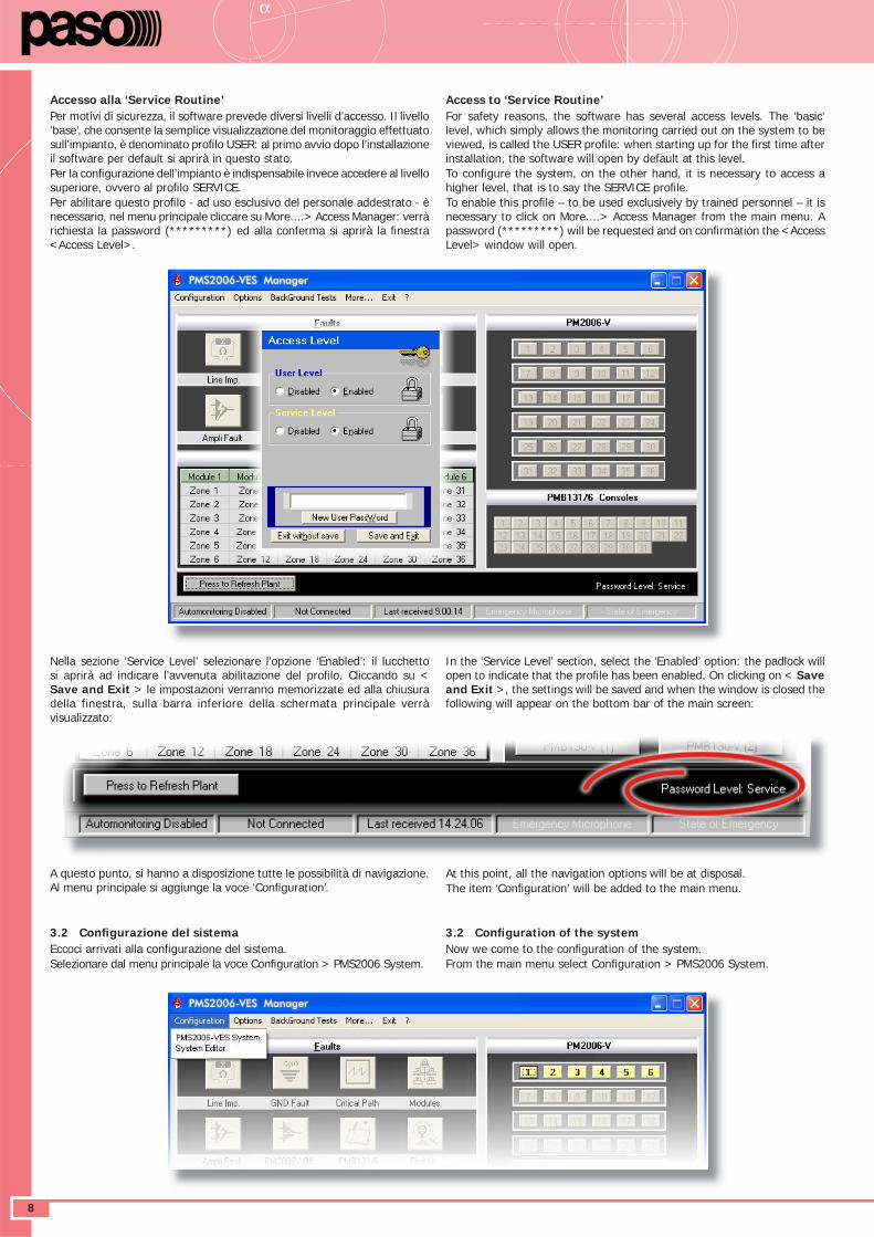
Accesso alla ‘Service Routine’ Per motivi di sicurezza, il software prevede diversi livelli d’accesso. Il livello ‘base’, che consente la semplice visualizzazione del monitoraggio effettuato sull’impianto, è denominato profi lo USER: al primo avvio dopo l’installazione il software per default si aprirà in questo stato.Per la confi gurazione dell’impianto è indispensabile invece accedere al livello superiore, ovvero al profi lo SERVICE.Per abilitare questo profi lo - ad uso esclusivo del personale addestrato - è necessario, nel menu principale cliccare su More....> Access Manager: verrà richiesta la password (*********) ed alla conferma si aprirà la fi nestra <Access Level>.
Nella sezione ‘Service Level’ selezionare l’opzione ‘Enabled’: il lucchetto si aprirà ad indicare l’avvenuta abilitazione del profi lo. Cliccando su < Save and Exit > le impostazioni verranno memorizzate ed alla chiusura della finestra, sulla barra inferiore della schermata principale verrà visualizzato:
A questo punto, si hanno a disposizione tutte le possibilità di navigazione. Al menu principale si aggiunge la voce ‘Confi guration’.
3.2 Confi gurazione del sistemaEccoci arrivati alla confi gurazione del sistema.Selezionare dal menu principale la voce Confi guration > PMS2006 System.
Access to ‘Service Routine’ For safety reasons, the software has several access levels. The ‘basic’ level, which simply allows the monitoring carried out on the system to be viewed, is called the USER profi le: when starting up for the fi rst time after installation, the software will open by default at this level.To confi gure the system, on the other hand, it is necessary to access a higher level, that is to say the SERVICE profi le.To enable this profi le – to be used exclusively by trained personnel – it is necessary to click on More....> Access Manager from the main menu. A password (*********) will be requested and on confi rmation the <Access Level> window will open.
In the ‘Service Level’ section, select the ‘Enabled’ option: the padlock will open to indicate that the profi le has been enabled. On clicking on < Save and Exit >, the settings will be saved and when the window is closed the following will appear on the bottom bar of the main screen:
At this point, all the navigation options will be at disposal.The item ‘Confi guration’ will be added to the main menu.
3.2 Confi guration of the systemNow we come to the confi guration of the system.From the main menu select Confi guration > PMS2006 System.
DATASHEET PMS2006-VES
9
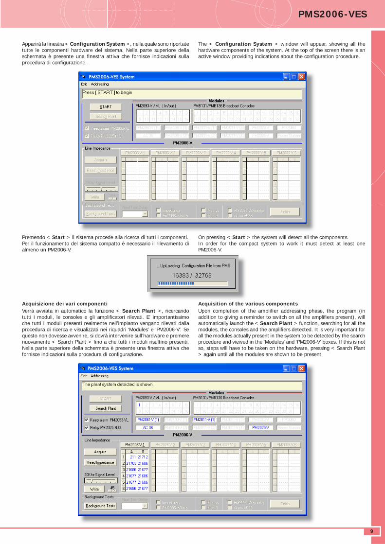
Apparirà la fi nestra < Confi guration System >, nella quale sono riportate tutte le componenti hardware del sistema. Nella parte superiore della schermata è presente una fi nestra attiva che fornisce indicazioni sulla procedura di confi gurazione.
Premendo < Start > il sistema procede alla ricerca di tutti i componenti.Per il funzionamento del sistema compatto è necessario il rilevamento di almeno un PM2006-V.
Acquisizione dei vari componentiVerrà avviata in automatico la funzione < Search Plant >, ricercando tutti i moduli, le consoles e gli amplifi catori rilevati. E’ importantissimo che tutti i moduli presenti realmente nell’impianto vengano rilevati dalla procedura di ricerca e visualizzati nei riquadri ‘Modules’ e ‘PM2006-V’. Se questo non dovesse avvenire, si dovrà intervenire sull’hardware e premere nuovamente < Search Plant > fi no a che tutti i moduli risultino presenti.Nella parte superiore della schermata è presente una fi nestra attiva che fornisce indicazioni sulla procedura di confi gurazione.
The < Confi guration System > window will appear, showing all the hardware components of the system. At the top of the screen there is an active window providing indications about the confi guration procedure.
On pressing < Start > the system will detect all the components.In order for the compact system to work it must detect at least one PM2006-V.
Acquisition of the various componentsUpon completion of the amplifi er addressing phase, the program (in addition to giving a reminder to switch on all the amplifi ers present), will automatically launch the < Search Plant > function, searching for all the modules, the consoles and the amplifi ers detected. It is very important for all the modules actually present in the system to be detected by the search procedure and viewed in the ‘Modules’ and ‘PM2006-V’ boxes. If this is not so, steps will have to be taken on the hardware, pressing < Search Plant > again until all the modules are shown to be present.
DATASHEETα
10
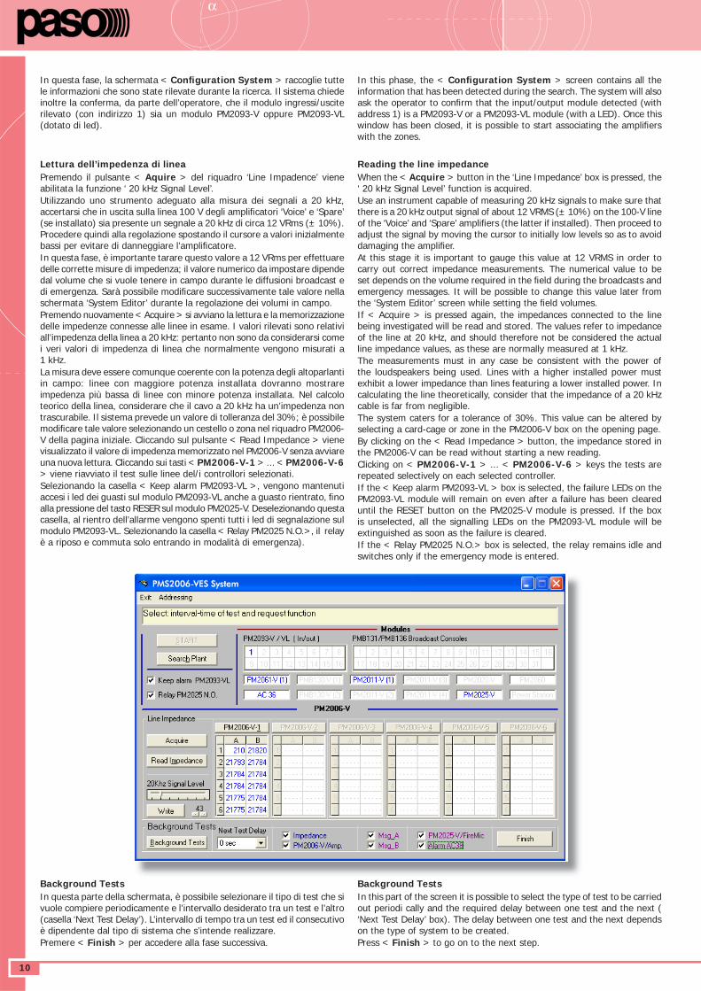
In questa fase, la schermata < Confi guration System > raccoglie tutte le informazioni che sono state rilevate durante la ricerca. Il sistema chiede inoltre la conferma, da parte dell’operatore, che il modulo ingressi/uscite rilevato (con indirizzo 1) sia un modulo PM2093-V oppure PM2093-VL (dotato di led).
Background TestsIn questa parte della schermata, è possibile selezionare il tipo di test che si vuole compiere periodicamente e l’intervallo desiderato tra un test e l’altro (casella ‘Next Test Delay’). L’intervallo di tempo tra un test ed il consecutivo è dipendente dal tipo di sistema che s’intende realizzare. Premere < Finish > per accedere alla fase successiva.
Lettura dell’impedenza di lineaPremendo il pulsante < Aquire > del riquadro ‘Line Impadence’ viene abilitata la funzione ‘ 20 kHz Signal Level’.Utilizzando uno strumento adeguato alla misura dei segnali a 20 kHz, accertarsi che in uscita sulla linea 100 V degli amplifi catori ‘Voice’ e ‘Spare’ (se installato) sia presente un segnale a 20 kHz di circa 12 VRms (± 10%). Procedere quindi alla regolazione spostando il cursore a valori inizialmente bassi per evitare di danneggiare l’amplifi catore. In questa fase, è importante tarare questo valore a 12 VRms per effettuare delle corrette misure di impedenza; il valore numerico da impostare dipende dal volume che si vuole tenere in campo durante le diffusioni broadcast e di emergenza. Sarà possibile modifi care successivamente tale valore nella schermata ‘System Editor’ durante la regolazione dei volumi in campo.Premendo nuovamente < Acquire > si avviano la lettura e la memorizzazione delle impedenze connesse alle linee in esame. I valori rilevati sono relativi all’impedenza della linea a 20 kHz: pertanto non sono da considerarsi come i veri valori di impedenza di linea che normalmente vengono misurati a 1 kHz. La misura deve essere comunque coerente con la potenza degli altoparlanti in campo: linee con maggiore potenza installata dovranno mostrare impedenza più bassa di linee con minore potenza installata. Nel calcolo teorico della linea, considerare che il cavo a 20 kHz ha un’impedenza non trascurabile. Il sistema prevede un valore di tolleranza del 30%; è possibile modifi care tale valore selezionando un cestello o zona nel riquadro PM2006-V della pagina iniziale. Cliccando sul pulsante < Read Impedance > viene visualizzato il valore di impedenza memorizzato nel PM2006-V senza avviare una nuova lettura. Cliccando sui tasti < PM2006-V-1 > ... < PM2006-V-6 > viene riavviato il test sulle linee del/i controllori selezionati. Selezionando la casella < Keep alarm PM2093-VL >, vengono mantenuti accesi i led dei guasti sul modulo PM2093-VL anche a guasto rientrato, fi no alla pressione del tasto RESER sul modulo PM2025-V. Deselezionando questa casella, al rientro dell’allarme vengono spenti tutti i led di segnalazione sul modulo PM2093-VL. Selezionando la casella < Relay PM2025 N.O.>, il relay è a riposo e commuta solo entrando in modalità di emergenza).
In this phase, the < Confi guration System > screen contains all the information that has been detected during the search. The system will also ask the operator to confi rm that the input/output module detected (with address 1) is a PM2093-V or a PM2093-VL module (with a LED). Once this window has been closed, it is possible to start associating the amplifi ers with the zones.
Reading the line impedanceWhen the < Acquire > button in the ‘Line Impedance’ box is pressed, the ‘ 20 kHz Signal Level’ function is acquired.Use an instrument capable of measuring 20 kHz signals to make sure that there is a 20 kHz output signal of about 12 VRMS (± 10%) on the 100-V line of the ‘Voice’ and ‘Spare’ amplifi ers (the latter if installed). Then proceed to adjust the signal by moving the cursor to initially low levels so as to avoid damaging the amplifi er. At this stage it is important to gauge this value at 12 VRMS in order to carry out correct impedance measurements. The numerical value to be set depends on the volume required in the fi eld during the broadcasts and emergency messages. It will be possible to change this value later from the ‘System Editor’ screen while setting the fi eld volumes.If < Acquire > is pressed again, the impedances connected to the line being investigated will be read and stored. The values refer to impedance of the line at 20 kHz, and should therefore not be considered the actual line impedance values, as these are normally measured at 1 kHz. The measurements must in any case be consistent with the power of the loudspeakers being used. Lines with a higher installed power must exhibit a lower impedance than lines featuring a lower installed power. In calculating the line theoretically, consider that the impedance of a 20 kHz cable is far from negligible. The system caters for a tolerance of 30%. This value can be altered by selecting a card-cage or zone in the PM2006-V box on the opening page.By clicking on the < Read Impedance > button, the impedance stored in the PM2006-V can be read without starting a new reading.Clicking on < PM2006-V-1 > ... < PM2006-V-6 > keys the tests are repeated selectively on each selected controller.If the < Keep alarm PM2093-VL > box is selected, the failure LEDs on the PM2093-VL module will remain on even after a failure has been cleared until the RESET button on the PM2025-V module is pressed. If the box is unselected, all the signalling LEDs on the PM2093-VL module will be extinguished as soon as the failure is cleared.If the < Relay PM2025 N.O.> box is selected, the relay remains idle and switches only if the emergency mode is entered.
Background TestsIn this part of the screen it is possible to select the type of test to be carried out periodi cally and the required delay between one test and the next ( ‘Next Test Delay’ box). The delay between one test and the next depends on the type of system to be created. Press < Finish > to go on to the next step.
DATASHEET PMS2006-VES
11
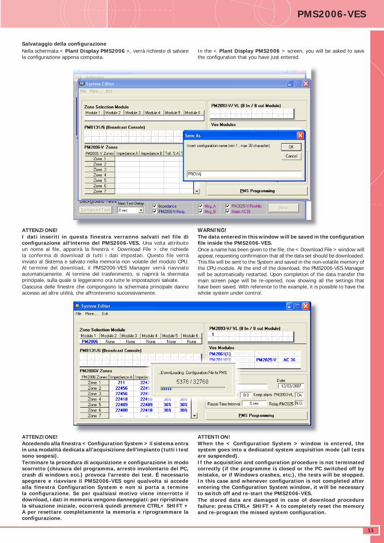
Salvataggio della confi gurazioneNella schermata < Plant Display PMS2006 >, verrà richiesto di salvare la confi gurazione appena composta.
ATTENZIONE!I dati inseriti in questa finestra verranno salvati nel file di confi gurazione all’interno del PMS2006-VES. Una volta attribuito un nome al fi le, apparirà la fi nestra < Download File > che richiede la conferma di download di tutti i dati impostati. Questo file verrà inviato al Sistema e salvato nella memoria non volatile del modulo CPU.Al termine del download, il PMS2006-VES Manager verrà riavviato automaticamente. Al termine del trasferimento, si riaprirà la shermata principale, sulla quale si leggeranno ora tutte le impostazioni salvate. Ciascuna delle fi nestre che compongono la schermata principale danno accesso ad altre utilità, che affronteremo successivamente.
ATTENZIONE!Accedendo alla fi nestra < Confi guration System > il sistema entra in una modalità dedicata all’acquisizione dell’impianto (tutti i test sono sospesi).Terminare la procedura di acquisizione e confi gurazione in modo scorretto (chiusura del programma, arresto involontario del PC, crash di windows ecc.) provoca l’arresto dei test. É necessario spegnere e riavviare il PMS2006-VES ogni qualvolta si accede alla finestra Configuration System e non si porta a termine la confi gurazione. Se per qualsiasi motivo viene interrotto il download, i dati in memoria vengono danneggiati: per ripristinare la situazione iniziale, occorrerà quindi premere CTRL+ SHIFT + A per resettare completamente la memoria e riprogrammare la confi gurazione.
In the < Plant Display PMS2006 > screen, you will be asked to save the confi guration that you have just entered.
WARNING!The data entered in this window will be saved in the confi guration fi le inside the PMS2006-VES.Once a name has been given to the fi le, the < Download File > window will appear, requesting confi rmation that all the data set should be downloaded. This fi le will be sent to the System and saved in the non-volatile memory of the CPU module. At the end of the download, the PMS2006-VES Manager will be automatically restarted. Upon completion of the data transfer the main screen page will be re-opened, now showing all the settings that have been saved. With reference to the example, it is possible to have the whole system under control.
ATTENTION!When the < Confi guration System > window is entered, the system goes into a dedicated system acquisition mode (all tests are suspended).If the acquisition and confi guration procedure is not terminated correctly (if the programme is closed or the PC switched off by mistake, or if Windows crashes, etc.), the tests will be stopped. In this case and whenever confi guration is not completed after entering the Confi guration System window, it will be necessary to switch off and re-start the PMS2006-VES.The stored data are damaged in case of download procedure failure: press CTRL+ SHIFT + A to completely reset the memory and re-program the missed system confi guration.
DATASHEETα
12
Funzione ‘Automonitoring’Nella parte sinistra della barra di stato sono presenti tre caselle, relative al monitoraggio dell’impianto. Se viene indicato <Automonitoring Disabled> la funzione è disabilitata, e sarà quindi necessario cliccare su <Press to Refresh Plant> nel caso si volesse interrogare l’impianto (interrogazione manuale). Se viceversa è indicato < Automonitoring Enabled >, la schermata viene automaticamente aggiornata ad un tempo stabilito dall’utente (ad es: ogni 3 secondi). Per abilitare/disabilitare questa funzione è suffi ciente cliccare una volta sulla casella stessa. Nelle due caselle a lato vengono indicati in tempo reale il test in corso e l’indicazione dell’orario in cui è avvenuta l’ultima interrogazione verso il PMS2006-VES .
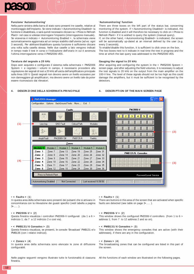
4. DESCRIZIONE DELLA SCHERMATA PRINCIPALE
• < Faults > (1)In questa area della schermata sono presenti dei pulsanti che si attivano in concomitanza con la rilevazione dei guasti specifi ci (vedi tabella a pagina 3•..... ).
• < PM2006-V > (2)Questa fi nestra visualizza i controllori PM2006-V confi gurati (da 1 a 6 > indirizzo 1; da 7 a 12 indirizzo 2 e così via).
• < PMB131/6 Consoles > (3)Questa fi nestra visualizza, se presenti, le console ‘Broadcast’ PMB131 e/o PMB136 (con i relativi indirizzi).
• < Zones > (4)In questa area della schermata sono elencate le zone di diffusione confi gurabili.
Nelle pagine seguenti vengono illustrate tutte le funzionalità di ciascuna fi nestra.
‘Automonitoring’ functionThere are three boxes on the left part of the status bar, concerning monitoring of the system. If <Automonitoring Disabled> is indicated, the function is disabled and it will therefore be necessary to click on <Press to Refresh Plant> if it is wished to query the system (manual query). If, on the other hand, <Automonitoring Enabled> is indicated, the screen will be automatically up-dated at an interval defi ned by the user (e.g. every 3 seconds).To enable/disable this function, it is suffi cient to click once on the box.The two boxes next to it indicate in real time the test in progress and the time at which the last query was addressed to the PMS2006-VES.
4. DESCRIPTION OF THE MAIN SCREEN PAGE
• < Faults > (1)There are buttons in this area of the screen that are activated when specifi c faults are detected (see table on page 3•..... ).
• < PM2006-V > (2)This window shows the confi gured PM2006-V controllers (from 1 to 6 > address 1; from 7 to 12 address 2 and so on).
• < PMB131/6 Consoles > (3)This window shows the emergency consoles that are active (with their addresses), if there are any in the confi guration.
• < Zones > (4)The broadcasting zones that can be confi gured are listed in this part of the screen.
All the functions of each window are illustrated on the following pages.
(1)
(4)
(2)
(3)
Taratura del segnale a 20 kHzDopo aver acquisito e confi gurato il sistema nella schermata < PMS2006 System > e regolato i volumi in campo, è necessario procedere alla regolazione dei segnali di test a 20 kHz all’usicta dell’amplifi catore principale sulla linea 100 V. Questi segnali non devono avere un livello eccessivo per non danneggiare gli amplifi catori, ma devono avere un livello tale da poter essere riconosciuto dai rilevatori.
Gauging the signal to 20 kHzAfter acquiring and confi guring the system in the < PMS2006 System > screen page, and after adjusting the fi eld volumes, it is necessary to adjust the test signals to 20 kHz on the output from the main amplifi er on the 100-V line. The level of these signals should not be too high as this could damage the amplifi ers, but it must be suffi cient to be recognised by the detectors.
DATASHEET PMS2006-VES
13
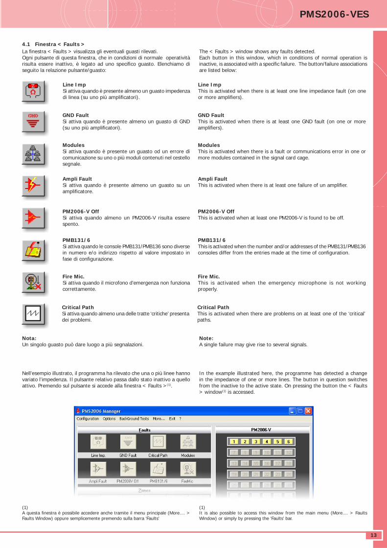
4.1 Finestra < Faults >La fi nestra < Faults > visualizza gli eventuali guasti rilevati.Ogni pulsante di questa fi nestra, che in condizioni di normale operatività risulta essere inattivo, è legato ad uno specifi co guasto. Elenchiamo di seguito la relazione pulsante/guasto:
Line ImpSi attiva quando è presente almeno un guasto impedenza di linea (su uno più amplifi catori).
GND FaultSi attiva quando è presente almeno un guasto di GND (su uno più amplifi catori).
ModulesSi attiva quando è presente un guasto od un errore di comunicazione su uno o più moduli contenuti nel cestello segnale.
Ampli FaultSi attiva quando è presente almeno un guasto su un amplifi catore.
PM2006-V OffSi attiva quando almeno un PM2006-V risulta essere spento.
PMB131/6Si attiva quando le console PMB131/PMB136 sono diverse in numero e/o indirizzo rispetto al valore impostato in fase di confi gurazione.
Fire Mic.Si attiva quando il microfono d’emergenza non funziona correttamente.
Critical PathSi attiva quando almeno una delle tratte ‘critiche’ presenta dei problemi.
Nota:Un singolo guasto può dare luogo a più segnalazioni.
Nell’esempio illustrato, il programma ha rilevato che una o più linee hanno variato l’impedenza. Il pulsante relativo passa dallo stato inattivo a quello attivo. Premendo sul pulsante si accede alla fi nestra < Faults >(1).
(1)A questa fi nestra è possibile accedere anche tramite il menu principale (More.... > Faults Window) oppure semplicemente premendo sulla barra ‘Faults’
The < Faults > window shows any faults detected.Each button in this window, which in conditions of normal operation is inactive, is associated with a specifi c failure. The button/failure associations are listed below:
Line ImpThis is activated when there is at least one line impedance fault (on one or more amplifi ers).
GND FaultThis is activated when there is at least one GND fault (on one or more amplifi ers).
ModulesThis is activated when there is a fault or communications error in one or more modules contained in the signal card cage.
Ampli FaultThis is activated when there is at least one failure of un amplifi er.
PM2006-V OffThis is activated when at least one PM2006-V is found to be off.
PMB131/6This is activated when the number and/or addresses of the PMB131/PMB136 consoles differ from the entries made at the time of confi guration.
Fire Mic.This is activated when the emergency microphone is not working properly.
Critical PathThis is activated when there are problems on at least one of the ‘critical’ paths.
Note:A single failure may give rise to several signals.
In the example illustrated here, the programme has detected a change in the impedance of one or more lines. The button in question switches from the inactive to the active state. On pressing the button the < Faults > window(1) is accessed.
(1)It is also possible to access this window from the main menu (More.... > Faults Window) or simply by pressing the ‘Faults’ bar.
DATASHEETα
14
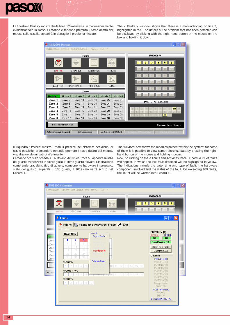
La fi nestra < Faults > mostra che la linea n°3 manifesta un malfunzionamento evidenziandolo in rosso. Cliccando e tenendo premuto il tasto destro del mouse sulla casella, apparirà in dettaglio il problema rilevato.
Il riquadro ‘Devices’ mostra i moduli presenti nel sistema: per alcuni di essi è possibile, premendo e tenendo premuto il tasto destro del mouse, visualizzare alcuni dati di riferimento. Cliccando ora sulla scheda < Faults and Activities Trace >, apparirà la lista dei guasti: evidenziato in colore giallo, l’ultimo guasto rilevato. L’indicazione comprende ora, data, tipo di guasto, componente hardware interessato, stato del guasto; superati i 100 guasti, il 101esimo verrà scritto nel Record 1.
The < Faults > window shows that there is a malfunctioning on line 3, highlighted in red. The details of the problem that has been detected can be displayed by clicking with the right-hand button of the mouse on the box and holding it down.
The ‘Devices’ box shows the modules present within the system: for some of them it is possible to view some reference data by pressing the right-hand button of the mouse and holding it down.Now, on clicking on the < Faults and Activities Trace > card, a list of faults will appear, in which the last fault detected will be highlighted in yellow. The indications include the date, time and type of fault, the hardware component involved and the status of the fault. On exceeding 100 faults, the 101st will be written into Record 1.
DATASHEET PMS2006-VES
15
Premendo sul pulsante ‘Read Trace’ si effettua un lettura in tempo reale della traccia; nel caso si volesse cancellare completamente la lista dei guasti sarà invece suffi ciente premere il pulsante ‘Clear Trace’.Nota: questa operazione è possibile unicamente nel profi lo ‘Service’.Questa fi nestra offre anche la possibilità di stampare il resoconto visualizzato (pulsante ‘Print’) e di salvarlo in un comune fi le di testo (pulsante ‘Save File’). Per uscire da questa fi nestra, cliccare sulla scheda <Exit>: si ritornerà alla schermata principale.
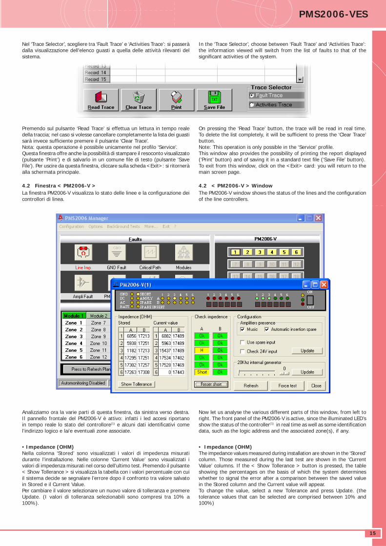
4.2 Finestra < PM2006-V >La fi nestra PM2006-V visualizza lo stato delle linee e la confi gurazione dei controllori di linea.
Analizziamo ora la varie parti di questa fi nestra, da sinistra verso destra. Il pannello frontale del PM2006-V è attivo: infatti i led accesi riportano in tempo reale lo stato del controllore(1) e alcuni dati identifi cativi come l’indirizzo logico e la/e eventuali zone associate.
• Impedance (OHM) Nella colonna ‘Stored’ sono visualizzati i valori di impedenza misurati durante l’installazione. Nelle colonne ‘Current Value’ sono visualizzati i valori di impedenza misurati nel corso dell’ultimo test. Premendo il pulsante < Show Tollerance > si visualizza la tabella con i valori percentuale con cui il sistema decide se segnalare l’errore dopo il confronto tra valore salvato in Stored e il Current Value.Per cambiare il valore selezionare un nuovo valore di tolleranza e premere Update. (I valori di tolleranza selezionabili sono compresi tra 10% a 100%).
On pressing the ‘Read Trace’ button, the trace will be read in real time. To delete the list completely, it will be suffi cient to press the ‘Clear Trace’ button. Note: This operation is only possible in the ‘Service’ profi le.This window also provides the possibility of printing the report displayed (‘Print’ button) and of saving it in a standard text fi le (‘Save File’ button).To exit from this window, click on the <Exit> card: you will return to the main screen page.
4.2 < PM2006-V > WindowThe PM2006-V window shows the status of the lines and the confi guration of the line controllers.
Now let us analyse the various different parts of this window, from left to right. The front panel of the PM2006-V is active, since the illuminated LED’s show the status of the controller(1) in real time as well as some identifi cation data, such as the logic address and the associated zone(s), if any.
• Impedance (OHM) The impedance values measured during installation are shown in the ‘Stored’ column. Those measured during the last test are shown in the ‘Current Value’ columns. If the < Show Tollerance > button is pressed, the table showing the percentages on the basis of which the system determines whether to signal the error after a comparison between the saved value in the Stored column and the Current value will appear.To change the value, select a new Tolerance and press Update. (the tolerance values that can be selected are comprised between 10% and 100%)
Nel ‘Trace Selector’, scegliere tra ‘Fault Trace’ e ‘Activities Trace’: si passerà dalla visualizzazione dell’elenco guasti a quella delle attività rilevanti del sistema.
In the ‘Trace Selector’, choose between ‘Fault Trace’ and ‘Activities Trace’: the information viewed will switch from the list of faults to that of the signifi cant activities of the system.
DATASHEETα
16
• Check Impedance Il riquadro ‘Check Impedance’ visualizza un resoconto del confronto tra impedenza misurata e ultima lettura per ogni linea. Nell’esempio della pagina precedente, la linea A3 ha misurato un impedenza più alta del 30% rispetto al valore salvato, mentre la Linea A6 è in corto circuito; dopo il rilevamento del corto-circuito la linea viene isolata. E’ possibile provare a reinserire le linee dopo il guasto premendo il pulsante < Reset short >. Questo comando ripristina tutte le linee in corto-circuito del PM2006-V. Per ripristinare singolarmente le linee, è necessario premere i tasti di ‘PROGRAM INSERTION’ direttamente sul pannello frontale del controllore.
• Confi guration Nel riquadro ‘Configuration’ è possibile impostare i parametri di confi gurazione del PM2006-V. Selezionando la casella ‘Music’ si indica la presenza dell’amplifi catore connesso all’ingresso relativo sul retro del controllore. Selezionando la casella ‘Automatic insertion spare’ si abilita il controllo della presenza e del funzionamento dell’amplifi catore connesso al morsetto ‘Spare’. In caso di guasto dell’amplifi catore ‘CALL’, verrà utilizzato l’amplifi catore di riserva ‘Spare’ fi no al ripristino dell’amplifi catore voce. Selezionando la casella ‘Use spare input’ forza l’utilizzo dell’amplifi catore di riserva al posto di quello principale. Selezionando ‘Check 24V input’ viene controllata la presenza del 24V sul morsetto ‘battery’, segnalato l’errore se il livello scende sotto i 20V e chiuso il relè AUX2 (si aprirà solo in caso di guasto). Per modifi care la confi gurazione selezionare i nuovi valori e premere il pulsante < UPDATE >.
• 20 kHz Internal Generator In questo riquadro si seleziona il livello del segnale 20 kHz miscelato all’ingresso audio del PM2006-V e presente in uscita sul connettore XLR.Premendo il pulsante < Refresh > vengono letti i parametri di confi gurazione ed impedenza; premendo il pulsante < Force test > viene eseguito il test dell’impedenza.
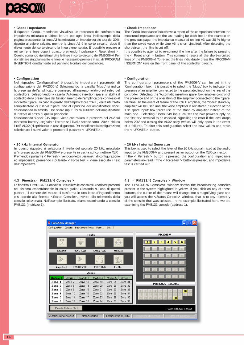
4.3 Finestra < PM131/6 Consoles >La fi nestra <PMB131/6 Consoles> visualizza le consoles Broadcast presenti nel sistema evidenziandole in colore giallo. Cliccando su uno di questi pulsanti, il cursore del mouse si trasforma in una lente d’ingrandimento e si accede alla fi nestra <Status Console>, ovvero alla telemetria della console selezionata. Nell’esempio illustrato, stiamo esaminando la console PMB131 (indirizzo 1).
• Check Impedance The ‘Check Impedance’ box shows a report of the comparison between the measured impedance and the last reading for each line. In the example on the previous page, the impedance measured on line A3 was 30 % higher than the saved value while Line A6 is short-circuited. After detecting the short-circuit the line is cut off. It is possible to attempt to re-connect the line after the failure by pressing the < Reset short > button. This command resets all the short-circuited lines of the PM2006-V. To re-set the lines individually press the ‘PROGRAM INSERTION’ keys on the front panel of the controller directly.
• Confi guration The configuration parameters of the PM2006-V can be set in the ‘Confi guration’ box. It is possible to select the ‘Music’ box to indicate the presence of an amplifi er connected to the associated input on the rear of the controller. Selecting the ‘Automatic insertion spare’ box enables control of the presence and of the operation of the amplifi er connected to the ‘Spare’ terminal. In the event of failure of the ‘CALL’ amplifi er, the ‘Spare’ stand-by amplifi er will be used until the voice amplifi er is reinstated. Selection of the ‘Use spare input’ box forces use of the stand-by amplifi er instead of the main one. Selecting ‘Check 24V input’ causes the 24V power supply on the ‘Battery’ terminal to be checked, signalling the error if the level drops below 20V and closing the AUX2 relay (which will only open in the event of a failure). To alter this confi guration select the new values and press the < UPDATE > button.
• 20 kHz Internal Generator This box is used to select the level of the 20 kHz signal mixed at the audio input to the PM2006-V and present as an output on the XLR connector.If the < Refresh > button is pressed, the confi guration and impedance parameters are read. If the < Force test > button is pressed, and impedance test is carried out.
4.3 < PM131/6 Consoles > WindowThe <PMB131/6 Consoles> window shows the broadcasting consoles present in the system highlighted in yellow. If you click on any of these buttons, the cursor of the mouse will change into a magnifying glass and you will access the <Status Console> window, that is to say telemetry of the console that was selected. In the example illustrated here, we are examining the PMB131 console (address 1).
DATASHEET PMS2006-VES
17
Questa fi nestra dà la possibilità di monitorare il funzionamento delle consoles ‘Broadcast’ e permette inoltre una serie di operazioni tra cui, ad esempio, variare il livello del segnale microfonico, abilitare o disabilitare i fi ltri, selezionare le zone d’ascolto, etc. In questa fase è anche possibile associare al tasto della console PMB131 una o più zone di diffusione: le zone ‘disponibili’, ovvero quelle presenti nell’impianto in esame, sono evidenziate in colore bianco (nell’esempio, essendoci nel sistema un solo PM2006-V, le zone sfruttabili sono 6). Per associare una zona alla console, è suffi ciente cliccare sulla zona desiderata: il pulsante diventa di colore rosso, a conferma dell’avvenuta selezione. Per selezionare tutte le zone, premere il pulsante <All On>; per disabilitarle premere <All Off>.Premendo <Reference> è possibile scrivere un commento alla console come fatto precedentemente per amplifi catori e terminazioni di linea.Al termine di tutte le modifi che, è indispensabile cliccare sul pulsante <Write Console> per far sì che vengano memorizzate e quindi messe in atto.
Nota: Per il modello PMB131, i campi ‘Monitor level’ ed ‘Intercom’ sono disabilitati in quanto relativi a funzioni non presenti sul modello stesso.
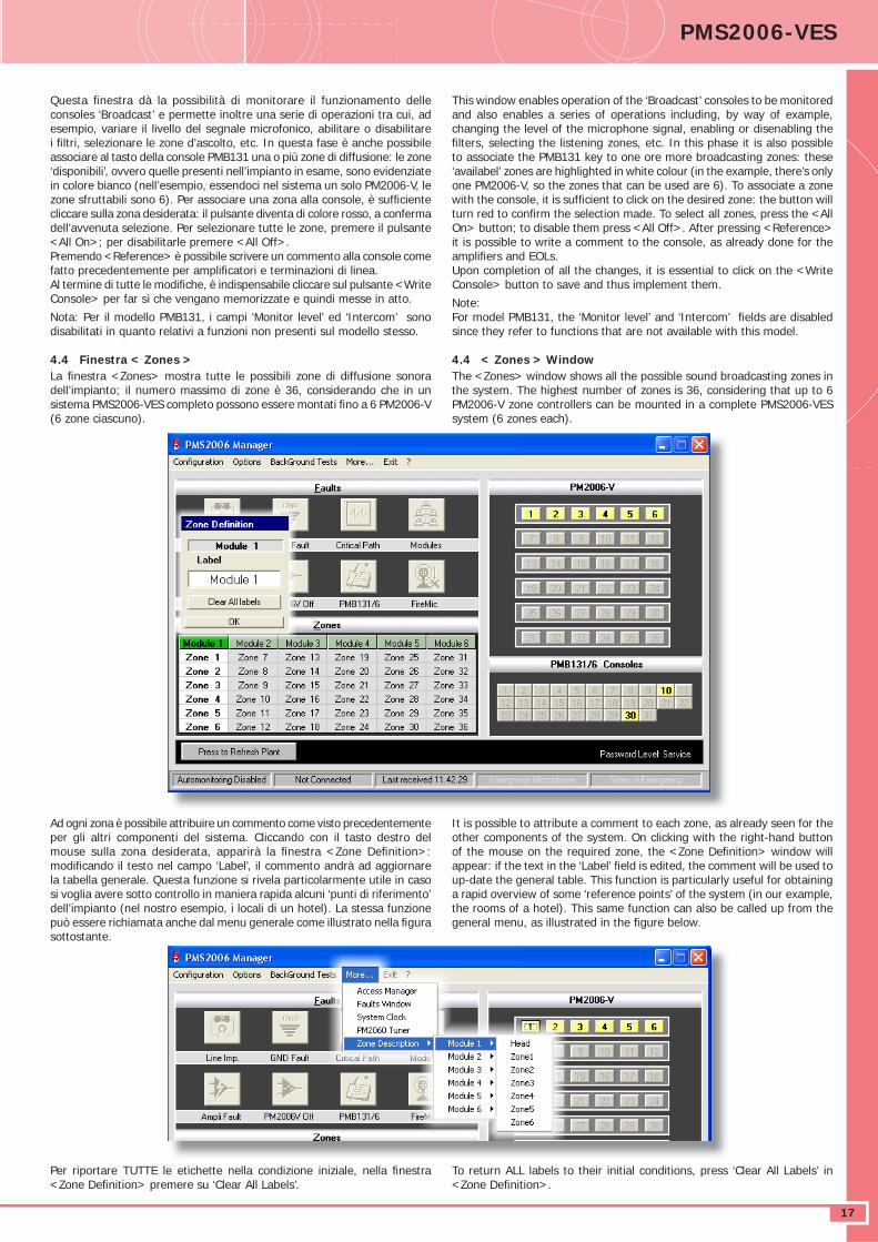
4.4 Finestra < Zones >La fi nestra <Zones> mostra tutte le possibili zone di diffusione sonora dell’impianto; il numero massimo di zone è 36, considerando che in un sistema PMS2006-VES completo possono essere montati fi no a 6 PM2006-V (6 zone ciascuno).
Ad ogni zona è possibile attribuire un commento come visto precedentemente per gli altri componenti del sistema. Cliccando con il tasto destro del mouse sulla zona desiderata, apparirà la fi nestra <Zone Defi nition>: modifi cando il testo nel campo ‘Label’, il commento andrà ad aggiornare la tabella generale. Questa funzione si rivela particolarmente utile in caso si voglia avere sotto controllo in maniera rapida alcuni ‘punti di riferimento’ dell’impianto (nel nostro esempio, i locali di un hotel). La stessa funzione può essere richiamata anche dal menu generale come illustrato nella fi gura sottostante.
Per riportare TUTTE le etichette nella condizione iniziale, nella fi nestra <Zone Defi nition> premere su ‘Clear All Labels’.
This window enables operation of the ‘Broadcast’ consoles to be monitored and also enables a series of operations including, by way of example, changing the level of the microphone signal, enabling or disenabling the fi lters, selecting the listening zones, etc. In this phase it is also possible to associate the PMB131 key to one ore more broadcasting zones: these ‘availabel’ zones are highlighted in white colour (in the example, there’s only one PM2006-V, so the zones that can be used are 6). To associate a zone with the console, it is suffi cient to click on the desired zone: the button will turn red to confi rm the selection made. To select all zones, press the <All On> button; to disable them press <All Off>. After pressing <Reference> it is possible to write a comment to the console, as already done for the amplifi ers and EOLs.Upon completion of all the changes, it is essential to click on the <Write Console> button to save and thus implement them.
Note:For model PMB131, the ‘Monitor level’ and ‘Intercom’ fi elds are disabled since they refer to functions that are not available with this model.
4.4 < Zones > WindowThe <Zones> window shows all the possible sound broadcasting zones in the system. The highest number of zones is 36, considering that up to 6 PM2006-V zone controllers can be mounted in a complete PMS2006-VES system (6 zones each).
It is possible to attribute a comment to each zone, as already seen for the other components of the system. On clicking with the right-hand button of the mouse on the required zone, the <Zone Defi nition> window will appear: if the text in the ‘Label’ fi eld is edited, the comment will be used to up-date the general table. This function is particularly useful for obtaining a rapid overview of some ‘reference points’ of the system (in our example, the rooms of a hotel). This same function can also be called up from the general menu, as illustrated in the fi gure below.
To return ALL labels to their initial conditions, press ‘Clear All Labels’ in <Zone Defi nition>.
DATASHEETα
18
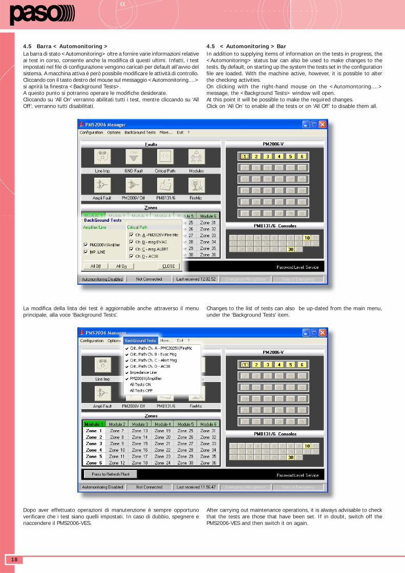
4.5 Barra < Automonitoring >La barra di stato <Automonitoring> oltre a fornire varie informazioni relative ai test in corso, consente anche la modifi ca di questi ultimi. Infatti, i test impostati nel fi le di confi gurazione vengono caricati per default all’avvio del sistema. A macchina attiva è però possibile modifi care le attività di controllo. Cliccando con il tasto destro del mouse sul messaggio <Automonitoring....> si aprirà la fi nestra <Background Tests>.A questo punto si potranno operare le modifi che desiderate.Cliccando su ‘All On’ verranno abilitati tutti i test, mentre cliccando su ‘All Off’, verranno tutti disabilitati.
La modifi ca della lista dei test è aggiornabile anche attraverso il menu principale, alla voce ‘Background Tests’.
Dopo aver effettuato operazioni di manutenzione è sempre opportuno verifi care che i test siano quelli impostati. In caso di dubbio, spegnere e riaccendere il PMS2006-VES.
4.5 < Automonitoring > BarIn addition to supplying items of information on the tests in progress, the <Automonitoring> status bar can also be used to make changes to the tests. By default, on starting up the system the tests set in the confi guration fi le are loaded. With the machine active, however, it is possible to alter the checking activities.On clicking with the right-hand mouse on the <Automontoring....> message, the <Background Tests> window will open.At this point it will be possible to make the required changes.Click on ‘All On’ to enable all the tests or on ‘All Off’ to disable them all.
Changes to the list of tests can also be up-dated from the main menu, under the ‘Background Tests’ item.
After carrying out maintenance operations, it is always advisable to check that the tests are those that have been set. If in doubt, switch off the PMS2006-VES and then switch it on again.
DATASHEET PMS2006-VES
19
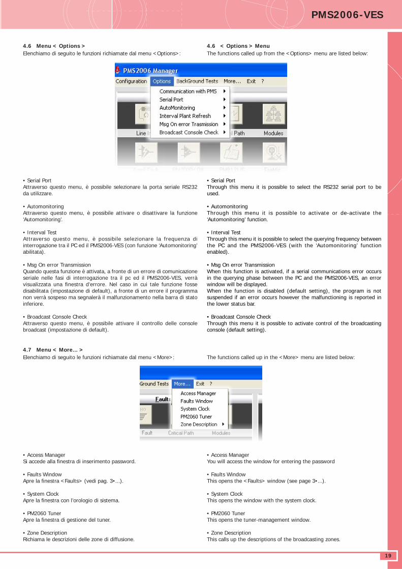
4.6 Menu < Options >Elenchiamo di seguito le funzioni richiamate dal menu <Options>:
4.7 Menu < More... >Elenchiamo di seguito le funzioni richiamate dal menu <More>:
• Access ManagerSi accede alla fi nestra di inserimento password.
• Faults WindowApre la fi nestra <Faults> (vedi pag. 3•...).
• System ClockApre la fi nestra con l’orologio di sistema.
• PM2060 TunerApre la fi nestra di gestione del tuner.
• Zone DescriptionRichiama le descrizioni delle zone di diffusione.
4.6 < Options > MenuThe functions called up from the <Options> menu are listed below:
The functions called up in the <More> menu are listed below:
• Serial PortAttraverso questo menu, è possibile selezionare la porta seriale RS232 da utilizzare.
• AutomonitoringAttraverso questo menu, è possibile attivare o disattivare la funzione ‘Automonitoring’.
• Interval TestAttraverso questo menu, è possibile selezionare la frequenza di interrogazione tra il PC ed il PMS2006-VES (con funzione ‘Automonitoring’ abilitata).
• Msg On error TransmissionQuando questa funzione è attivata, a fronte di un errore di comunicazione seriale nelle fasi di interrogazione tra il pc ed il PMS2006-VES, verrà visualizzata una fi nestra d’errore. Nel caso in cui tale funzione fosse disabilitata (impostazione di default), a fronte di un errore il programma non verrà sospeso ma segnalerà il malfunzionamento nella barra di stato inferiore.
• Broadcast Console CheckAttraverso questo menu, è possibile attivare il controllo delle console broadcast (impostazione di default).
• Serial PortThrough this menu it is possible to select the RS232 serial port to be used.
• AutomonitoringThrough this menu it is possible to activate or de-activate the ‘Automonitoring’ function.
• Interval TestThrough this menu it is possible to select the querying frequency between the PC and the PMS2006-VES (with the ‘Automonitoring’ function enabled).
• Msg On error TransmissionWhen this function is activated, if a serial communications error occurs in the querying phase between the PC and the PMS2006-VES, an error window will be displayed.When the function is disabled (default setting), the program is not suspended if an error occurs however the malfunctioning is reported in the lower status bar.
• Broadcast Console CheckThrough this menu it is possible to activate control of the broadcasting console (default setting).
• Access ManagerYou will access the window for entering the password
• Faults WindowThis opens the <Faults> window (see page 3•...).
• System ClockThis opens the window with the system clock.
• PM2060 TunerThis opens the tuner-management window.
• Zone DescriptionThis calls up the descriptions of the broadcasting zones.
DATASHEETα
20
5. PROGRAMMAZIONE5.1 Cenni sulla normativa IEC 60849 (CEI 100 55)E’ possibile riassumere brevemente quelli che sono, per la parte che riguarda la diffusione sonora, i punti focali della normativa IEC 60849.
• Il sistema deve essere in grado di operare in modalità totalmente automatizzata oppure sotto il controllo diretto del personale preposto.
• Messaggi preregistrati - Il supporto dei dati deve essere di tipo non volatile e preferibilmente
a stato solido. - I messaggi devono essere due: uno di allarme e l’altro di allerta. - I messaggi preregistrati devono essere continuamente monitorati al
fi ne di garantirne la disponibilità e l’integrità. - I messaggi non devono essere corrotti o danneggiati da sorgenti
esterne non autorizzate.
• Distribuzione dei messaggi in differenti zone di diffusione
• Informazioni in tempo reale da parte del personale preposto attraverso il ‘microfono d’emergenza’
• Indicazioni relative a malfunzionamenti del sistema - guasto alimentazione primaria. - guasto alimentazione secondaria. - guasto al circuito di ricarica e controllo stato batterie. - rottura fusibili. - guasto/malfunzionamento del microfono d’emergenza, incluso la
capsula, lo stadio di preamplifi cazione e il cavo di collegamento. - guasto/malfunzionamento di ogni tratta di collegamento tra gli
amplifi catori e le sorgenti critiche (microfono d’emergenza, generatore di messaggi).
- assenza di uno o più componenti che compongono l’impianto. - guasto relativo ai generatori di segnale d’emergenza. - guasto di ogni linea altoparlanti. - guasto di un processo software. - guasto durante una fase di verifi ca alla memoria. - eventuali guasti di comunicazione tra le varie parti del sistema. - Il sistema deve essere in grado di segnalare il guasto riscontrato
durante l’analisi entro 100 secondi.
• Monitoraggio del microprocessore - La circuiteria di monitoraggio della scheda CPU deve evitare che un
guasto attribuibile al microprocessore produca segnalazioni di guasto e verifi care il corretto svolgimento delle principali routine.
- In caso d’intervento della procedura d’inizializzazione del sistema, lo stesso deve rendersi operativo entro 10 secondi.
- Memorizzazione di almeno 100 eventi relativi a malfunzionamenti del sistema. La cancellazione di tali record potrà avvenire solo dal personale autorizzato
- La comunicazione con il sistema antincendio/emergenza deve essere continuamente verifi cata.
• Alimentazione secondaria - Deve garantire il funzionamento per un tempo pari a quello stimato
dalle autorità competenti per l’intera evacuazione dello stabile; in ogni caso non minore di 30 minuti.
- Funzionamento in stand-by: conseguentemente al fatto che sia previsto o meno un generatore d’emergenza per l’alimentazione primaria, l’alimentazione secondaria deve garantire un mantenimento in stand-by pari ad almeno 6h (con generatore) oppure 24h (senza generatore).
In entrambi i casi deve essere garantita la procedura d’emergenza per altri 30 minuti.
- Quando è attiva l’alimentazione d’emergenza, al fi ne di ridurre il consumo d’energia, è consentito eliminare le sorgenti musicali secondarie (ex: musica di sottofondo).
5. PROGRAMMING5.1 Outline of IEC standard 60849 (CEI 100 55)As far as concerns the sound-broadcasting part, it is possible to summarise briefl y here the main points of IEC standard 60849.
• The system must be capable of operating in a fully automated fashion or under the direct control of the personnel responsible for this function.
• Pre-recorded messages - IThe medium on which the data are recorded must be of the non-
volatile and preferably solid-state type. - There must be two messages: one alarm message and one alert
message. - The pre-recorded messages must be monitored continuously in order
to ensure their availability and integrity. - The messages must not be corrupted or damaged by unauthorised
outside sources.• Distribution of the messages to different broadcasting zones
• Real-time information from the personnel in charge through the ‘emergency microphone’
• Indications concerning system malfunctioning - failure of primary power supply. - failure of secondary power supply. - failure of the battery recharging and status control circuit. - breakage of fuses. - failure /malfunctioning of the emergency microphone, including the
capsule, the pre-amplifi cation stage and the connecting cable. - failure /malfunctioning of each stretch connecting the amplifi ers to
the critical sources (emergency microphone, message generator). - absence of one or more components forming the system. - failure affecting the emergency signal generators. - failure of each loudspeaker line. - failure of a software process. - failure during a memory checking phase. - possible failure of communications between the various different parts
of the system. - The system must be capable of signalling any failure found during
the analysis within 100 seconds.
• Monitoring the microprocessor - The CPU card monitoring circuitry must prevent a failure attributable
to the microprocessor from producing failure signalling and check correct performance of the main routines.
- If the system initialisation procedure is triggered off, it must become operational within 10 seconds.
- Storage of at least 100 events relating to system malfunctioning. These records may only be deleted by authorised personnel.
- Communication with the fi re-fi ghting/emergency system must be checked continuously.
• Secondary power supply - This must ensure operation for a period equal to that estimated by the
appropriate authorities as required for evacuating the while building, and in any case for not less than 30 minutes.
- Operation on stand-by: depending on whether or not an emergency generator is provided for the primary power supply, the secondary power supply must ensure up-keep of the system on stand-by for at least 6 hours (with a generator) or for 24 hours (without a generator). In both cases, the emergency procedure must be ensured for a further period of 30 minutes.
- When the emergency power supply is active, elimination of the secondary music sources (e.g. background music) is permitted in order to lower power consumption).
DATASHEET PMS2006-VES
21
5.2 Il sistema realizzato da PasoIl sistema VES realizzato da Paso può essere proposto come integrazione di un classico sistema di broadcast composto da postazioni microfoniche, musica di sottofondo, sorgenti ausiliarie etc. Durante lo svolgimento delle normali attività di diffusione, una serie di test operano in modalità background senza procurare intralci o interruzioni alla diffusione dei messaggi o della musica di sottofondo. La presenza della componentistica necessaria alla realizzazione del sistema VES, anche se continuamente verifi cata, rimane latente fi no a che non si verifi ca un evento d’emergenza. Infatti è solo in fase d’emergenza che il sistema VES manifesta la propria priorità sul sistema Broadcast.
I test che vengono svolti automaticamente dal sistema assicurano:1) Comunicazione delle schede installate all’interno del cestello con la
CPU.
2) L’integrità dei messaggi preregistrati di allarme e di allerta contenuti nel modulo PM2061-V.
3) L’integrità delle tratte critiche di collegamento (Critical Path) tra PM2006-V e le seguenti sorgenti critiche:
- PM2061-V Messaggio 1 (livello analogico e chksum) - PM2061-V Messaggio 2 (livello analogico e chksum) - modulo AC38 (generatore di toni)
4) Monitoraggio degli alimentatori PM2011-V (‘mains’ e ‘backup 24Vcc’).
5) Rilevazione della presenza delle console broadcast PMB131 e PMB136(1).
• Caratteristiche del PMS2006-VES ManagerIl sistema PMS2006-VES Manager necessita di una serie di procedure di programmazione e di controllo che richiedono l’utilizzo di un personal computer e di un software dedicato. Questo software è stato ideato e realizzato solo ed unicamente per essere utilizzato con il Sistema Modulare PMS2006-VES Paso.
Il PMS2006-VES Manager assolve principalmente a quattro scopi:• Messa in funzione del sistema• Monitoraggio, diagnosi e stampa dei guasti avvenuti• Telemetria console ed amplifi catori• Stampa/salvataggio dei guasti e delle attività dell’impianto.
• Note sull’installazioneIl progetto di un’impianto di diffusione sonora che debba soddisfare i requisiti esposti nella normativa IEC 60849, richiede principalmente che questo venga realizzato seguendo tecniche, accorgimenti e procedure che concorrano ad elevare l’affi dabilità e l’effi cienza del sistema.Ad esempio:- La disposizione dei diffusori deve garantire una buona ed omogenea
intellegibilità, questo incide sia sulla scelta dei diffusori e sia sul numero degli stessi.
- Considerare sempre un margine di riserva del 10-15% tra la potenza degli altoparlanti e la potenza dell’amplifi catore impiegato.
- Assicurarsi che sia garantita una buona ventilazione degli amplifi catori.
- L’installatore, al fi ne di garantire una buona immunità dai falsi allarmi, deve assicurarsi che i collegamenti elettrici tra i vari elementi non siano critici.
(1) Non richiesta dalla normativa.
• Limiti massimi dell’impianto VES PasoIl sistema PMS2006-VES, come indicato precedentemente, viene composto da una serie di moduli che si integrano al classico sistema PA e la cui presenza rimane latente fi no a che non si verifi ca un’emergenza. Nella tabella che segue sono evidenziati, nell’ambito della componentistica del PMS2006-VES, i moduli indispensabili per ottenere un impianto VES.
5.2 The system designed by PasoThe VES system designed by Paso may be proposed for completing a traditional broadcasting system consisting of microphone stations, background music, auxiliary sources etc. While the normal broadcasting activities are taking place, a set of tests are carried out in the background mode without causing any obstacles or interruptions in the messages or in the background music being broadcast. The presence of the components required to implement the VES is constantly checked, however these components remain latent until an emergency event occurs. It is only in emergencies that the VES system asserts its priority over the broadcasting system, meeting the requisites described in the standard.The tests carried out automatically by the system provide the following:
1) Communications between the cards installed inside the card cage with the CPU module.
2) Integrity of the pre-recorded alarm and alerting messages contained in the PM2061-V module.
3) Integrity of the critical paths (Critical Path) connecting the PM2006-V and the following critical sources:
- PM2061-V Message 1 (analogue level and chksum) - PM2061-V Message 2 (analogue level and chksum) - AC38 module (tone generator)
4) Monitoring of power supply unit (‘mains’ and ’24 VDC backup’).
5) Detection of the presence of the PMB131 and PMB136(1) broadcasting consoles.
• Specifi cations of the PMS2006-VES ManagerThe PMS2006-VES system requires a series of programming and control procedures that entail the use of a personal computer and dedicated software. This software was designed and created solely for use with the Paso PMS2006-VES Modular System.
The PMS2006-VES Manager carries out four functions:• Commissioning of the system• Monitoring, diagnosis and printing of failures that have occurred• Remote measurements for consoles and amplifi ers• Printing/saving of failures and of the system activities.
• Notes on installationIn order for the project of a sound-broadcasting system to meet the requirements et out in IEC standard 60849, the system must be made on the basis of techniques, arrangements and procedures that contribute towards raising the reliability and effi ciency of the system.For example:- The arrangement of the speaker units must ensure a good and uniform
intelligibility; this affects both the choice of the speaker units and their number.
- Always consider a margin of 10-15% between the output of the loudspeakers and the output of the amplifi er being used.
- Make sure that proper ventilation of the amplifi ers is provided.- In order to ensure a good level of immunity from false alarms, the
installer must make sure that the wiring connections between the various different components are not critical.
• Maximum limits of the Paso VES As already indicated, the PMS2006-VES system is made up of a series of modules that can be added to a traditional PA system, and the presence of which remains latent until an emergency occurs. In the framework of the components of the PMS2006-VES, the following table shows the modules that are essential for obtaining a VES.
(1) Not required according to the standard.
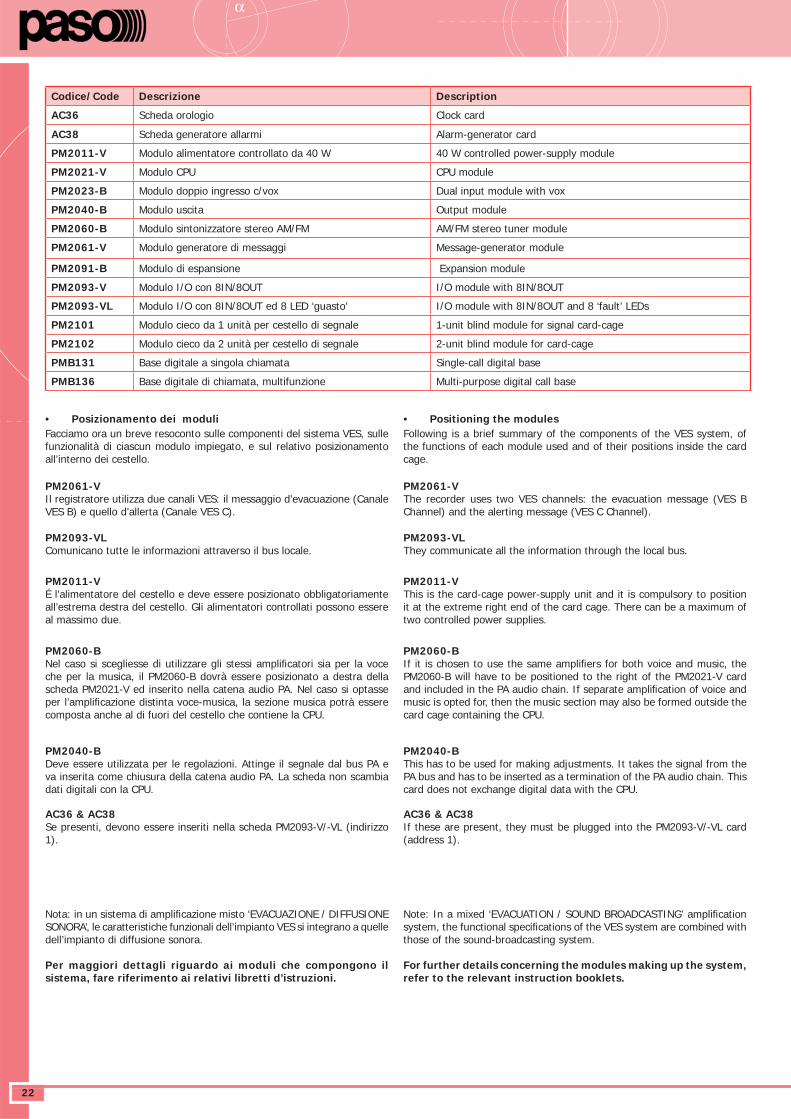
DATASHEETα
22
Codice/Code Descrizione Description
AC36 Scheda orologio Clock card
AC38 Scheda generatore allarmi Alarm-generator card
PM2011-V Modulo alimentatore controllato da 40 W 40 W controlled power-supply module
PM2021-V Modulo CPU CPU module
PM2023-B Modulo doppio ingresso c/vox Dual input module with vox
PM2040-B Modulo uscita Output module
PM2060-B Modulo sintonizzatore stereo AM/FM AM/FM stereo tuner module
PM2061-V Modulo generatore di messaggi Message-generator module
PM2091-B Modulo di espansione Expansion module
PM2093-V Modulo I/O con 8IN/8OUT I/O module with 8IN/8OUT
PM2093-VL Modulo I/O con 8IN/8OUT ed 8 LED ‘guasto’ I/O module with 8IN/8OUT and 8 ‘fault’ LEDs
PM2101 Modulo cieco da 1 unità per cestello di segnale 1-unit blind module for signal card-cage
PM2102 Modulo cieco da 2 unità per cestello di segnale 2-unit blind module for card-cage
PMB131 Base digitale a singola chiamata Single-call digital base
PMB136 Base digitale di chiamata, multifunzione Multi-purpose digital call base
• Posizionamento dei moduliFacciamo ora un breve resoconto sulle componenti del sistema VES, sulle funzionalità di ciascun modulo impiegato, e sul relativo posizionamento all’interno dei cestello.
PM2061-VIl registratore utilizza due canali VES: il messaggio d’evacuazione (Canale VES B) e quello d’allerta (Canale VES C).
PM2093-VLComunicano tutte le informazioni attraverso il bus locale.
PM2011-VÉ l’alimentatore del cestello e deve essere posizionato obbligatoriamente all’estrema destra del cestello. Gli alimentatori controllati possono essere al massimo due.
PM2060-BNel caso si scegliesse di utilizzare gli stessi amplifi catori sia per la voce che per la musica, il PM2060-B dovrà essere posizionato a destra della scheda PM2021-V ed inserito nella catena audio PA. Nel caso si optasse per l’amplifi cazione distinta voce-musica, la sezione musica potrà essere composta anche al di fuori del cestello che contiene la CPU.
PM2040-BDeve essere utilizzata per le regolazioni. Attinge il segnale dal bus PA e va inserita come chiusura della catena audio PA. La scheda non scambia dati digitali con la CPU.
AC36 & AC38Se presenti, devono essere inseriti nella scheda PM2093-V/-VL (indirizzo 1).
Nota: in un sistema di amplifi cazione misto ‘EVACUAZIONE / DIFFUSIONE SONORA’, le caratteristiche funzionali dell’impianto VES si integrano a quelle dell’impianto di diffusione sonora.
Per maggiori dettagli riguardo ai moduli che compongono il sistema, fare riferimento ai relativi libretti d’istruzioni.
• Positioning the modulesFollowing is a brief summary of the components of the VES system, of the functions of each module used and of their positions inside the card cage.
PM2061-VThe recorder uses two VES channels: the evacuation message (VES B Channel) and the alerting message (VES C Channel).
PM2093-VLThey communicate all the information through the local bus.
PM2011-VThis is the card-cage power-supply unit and it is compulsory to position it at the extreme right end of the card cage. There can be a maximum of two controlled power supplies.
PM2060-BIf it is chosen to use the same amplifi ers for both voice and music, the PM2060-B will have to be positioned to the right of the PM2021-V card and included in the PA audio chain. If separate amplifi cation of voice and music is opted for, then the music section may also be formed outside the card cage containing the CPU.
PM2040-BThis has to be used for making adjustments. It takes the signal from the PA bus and has to be inserted as a termination of the PA audio chain. This card does not exchange digital data with the CPU.
AC36 & AC38If these are present, they must be plugged into the PM2093-V/-VL card (address 1).
Note: In a mixed ‘EVACUATION / SOUND BROADCASTING’ amplifi cation system, the functional specifi cations of the VES system are combined with those of the sound-broadcasting system.
For further details concerning the modules making up the system, refer to the relevant instruction booklets.
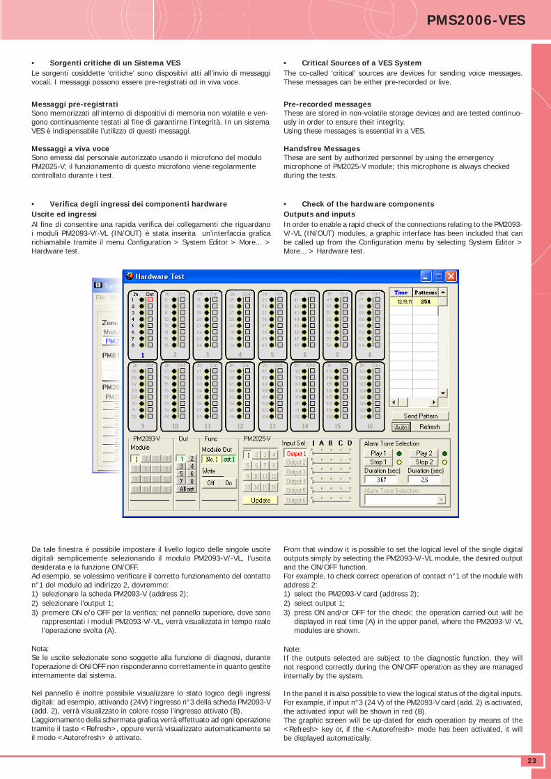
DATASHEET PMS2006-VES
23
• Sorgenti critiche di un Sistema VESLe sorgenti cosiddette ‘critiche’ sono dispositivi atti all’invio di messaggi vocali. I messaggi possono essere pre-registrati od in viva voce.
Messaggi pre-registratiSono memorizzati all’interno di dispositivi di memoria non volatile e ven-gono continuamente testati al fi ne di garantirne l’integrità. In un sistema VES è indispensabile l’utilizzo di questi messaggi.
Messaggi a viva voceSono emessi dal personale autorizzato usando il microfono del modulo PM2025-V; il funzionamento di questo microfono viene regolarmente controllato durante i test.
• Verifi ca degli ingressi dei componenti hardwareUscite ed ingressiAl fi ne di consentire una rapida verifi ca dei collegamenti che riguardano i moduli PM2093-V/-VL (IN/OUT) è stata inserita un’interfaccia grafi ca richiamabile tramite il menu Confi guration > System Editor > More... > Hardware test.
Da tale fi nestra è possibile impostare il livello logico delle singole uscite digitali semplicemente selezionando il modulo PM2093-V/-VL, l’uscita desiderata e la funzione ON/OFF.Ad esempio, se volessimo verifi care il corretto funzionamento del contatto n°1 del modulo ad indirizzo 2, dovremmo:1) selezionare la scheda PM2093-V (address 2);2) selezionare l’output 1;3) premere ON e/o OFF per la verifi ca; nel pannello superiore, dove sono
rappresentati i moduli PM2093-V/-VL, verrà visualizzata in tempo reale l’operazione svolta (A).
Nota:Se le uscite selezionate sono soggette alla funzione di diagnosi, durante l’operazione di ON/OFF non risponderanno correttamente in quanto gestite internamente dal sistema.
Nel pannello è inoltre possibile visualizzare lo stato logico degli ingressi digitali: ad esempio, attivando (24V) l’ingresso n°3 della scheda PM2093-V (add. 2), verrà visualizzato in colore rosso l’ingresso attivato (B). L’aggiornamento della schermata grafi ca verrà effettuato ad ogni operazione tramite il tasto <Refresh>, oppure verrà visualizzato automaticamente se il modo <Autorefresh> è attivato.
• Critical Sources of a VES SystemThe co-called ‘critical’ sources are devices for sending voice messages. These messages can be either pre-recorded or live.
Pre-recorded messagesThese are stored in non-volatile storage devices and are tested continuo-usly in order to ensure their integrity.Using these messages is essential in a VES.
Handsfree MessagesThese are sent by authorized personnel by using the emergency microphone of PM2025-V module; this microphone is always checked during the tests.
• Check of the hardware componentsOutputs and inputs In order to enable a rapid check of the connections relating to the PM2093-V/-VL (IN/OUT) modules, a graphic interface has been included that can be called up from the Confi guration menu by selecting System Editor > More... > Hardware test.
From that window it is possible to set the logical level of the single digital outputs simply by selecting the PM2093-V/-VL module, the desired output and the ON/OFF function.For example, to check correct operation of contact n°1 of the module with address 2:1) select the PM2093-V card (address 2);2) select output 1;3) press ON and/or OFF for the check; the operation carried out will be
displayed in real time (A) in the upper panel, where the PM2093-V/-VL modules are shown.
Note:If the outputs selected are subject to the diagnostic function, they will not respond correctly during the ON/OFF operation as they are managed internally by the system.
In the panel it is also possible to view the logical status of the digital inputs. For example, if input n°3 (24 V) of the PM2093-V card (add. 2) is activated, the activated input will be shown in red (B). The graphic screen will be up-dated for each operation by means of the <Refresh> key or, if the <Autorefresh> mode has been activated, it will be displayed automatically.
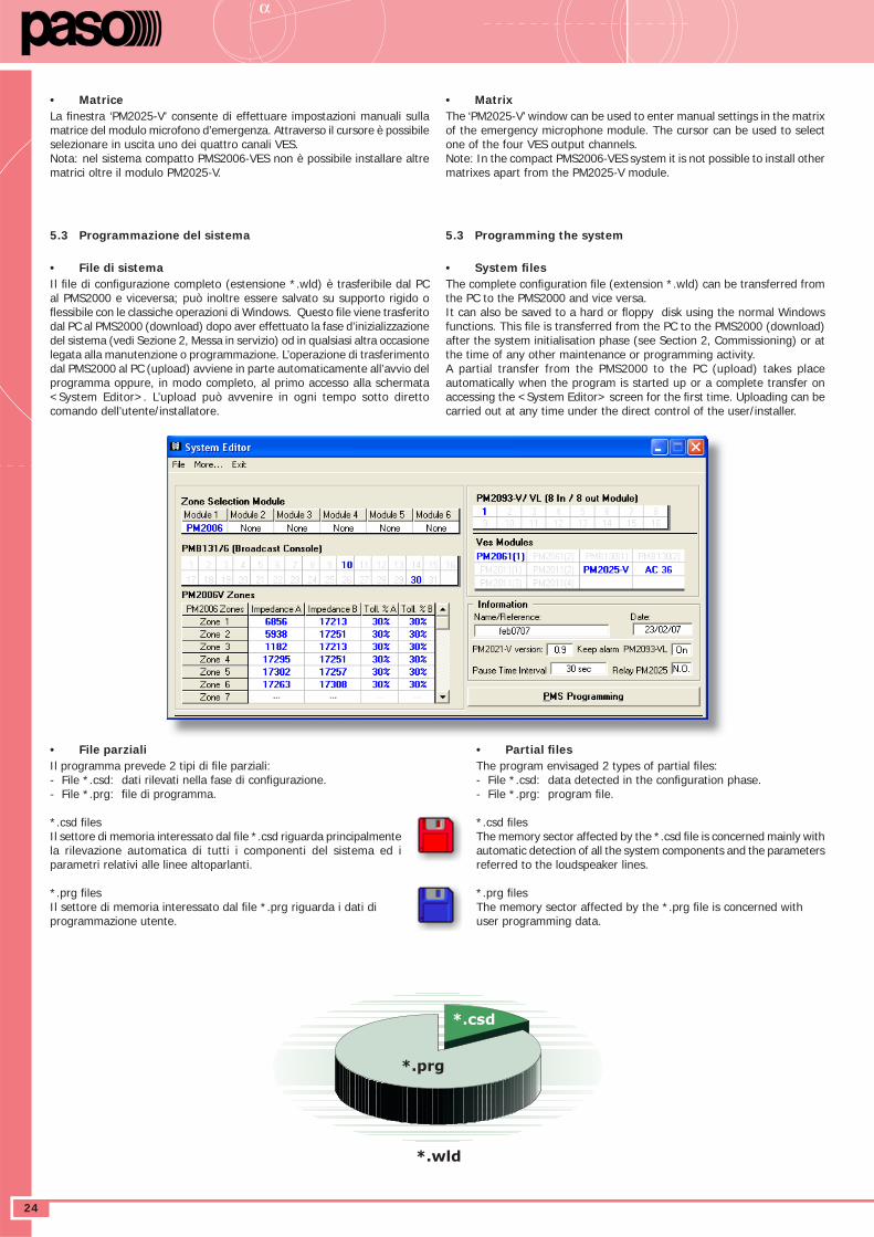
DATASHEETα
24
• MatriceLa fi nestra ‘PM2025-V’ consente di effettuare impostazioni manuali sulla matrice del modulo microfono d’emergenza. Attraverso il cursore è possibile selezionare in uscita uno dei quattro canali VES.Nota: nel sistema compatto PMS2006-VES non è possibile installare altre matrici oltre il modulo PM2025-V.
5.3 Programmazione del sistema
• File di sistemaIl fi le di confi gurazione completo (estensione *.wld) è trasferibile dal PC al PMS2000 e viceversa; può inoltre essere salvato su supporto rigido o fl essibile con le classiche operazioni di Windows. Questo fi le viene trasferito dal PC al PMS2000 (download) dopo aver effettuato la fase d’inizializzazione del sistema (vedi Sezione 2, Messa in servizio) od in qualsiasi altra occasione legata alla manutenzione o programmazione. L’operazione di trasferimento dal PMS2000 al PC (upload) avviene in parte automaticamente all’avvio del programma oppure, in modo completo, al primo accesso alla schermata <System Editor>. L’upload può avvenire in ogni tempo sotto diretto comando dell’utente/installatore.
• File parzialiIl programma prevede 2 tipi di fi le parziali:- File *.csd: dati rilevati nella fase di confi gurazione.- File *.prg: fi le di programma.
*.csd fi lesIl settore di memoria interessato dal fi le *.csd riguarda principalmente la rilevazione automatica di tutti i componenti del sistema ed i parametri relativi alle linee altoparlanti.
*.prg fi lesIl settore di memoria interessato dal fi le *.prg riguarda i dati di programmazione utente.
• MatrixThe ‘PM2025-V’ window can be used to enter manual settings in the matrix of the emergency microphone module. The cursor can be used to select one of the four VES output channels.Note: In the compact PMS2006-VES system it is not possible to install other matrixes apart from the PM2025-V module.
5.3 Programming the system
• System fi lesThe complete confi guration fi le (extension *.wld) can be transferred from the PC to the PMS2000 and vice versa.It can also be saved to a hard or fl oppy disk using the normal Windows functions. This fi le is transferred from the PC to the PMS2000 (download) after the system initialisation phase (see Section 2, Commissioning) or at the time of any other maintenance or programming activity.A partial transfer from the PMS2000 to the PC (upload) takes place automatically when the program is started up or a complete transfer on accessing the <System Editor> screen for the fi rst time. Uploading can be carried out at any time under the direct control of the user/installer.
• Partial fi lesThe program envisaged 2 types of partial fi les:- File *.csd: data detected in the confi guration phase.- File *.prg: program fi le.
*.csd fi lesThe memory sector affected by the *.csd fi le is concerned mainly with automatic detection of all the system components and the parameters referred to the loudspeaker lines.
*.prg fi lesThe memory sector affected by the *.prg fi le is concerned with user programming data.
*.prg
*.csd
*.wld
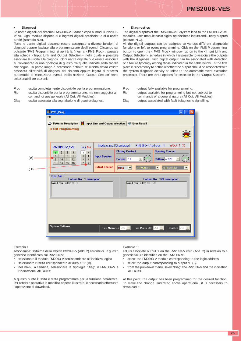
DATASHEET PMS2006-VES
25
• DiagnosiLe uscite digitali del sistema PMS2006-VES fanno capo ai moduli PM2093-V/-VL. Ogni modulo dispone di 8 ingressi digitali optoisolati e di 8 uscite a relé (scambio N.A).Tutte le uscite digitali possono essere assegnate a diverse funzioni di diagnosi oppure lasciate alla programmazione degli eventi. Cliccando sul pulsante ‘PMS Programming’ si aprirà la fi nestra <PMS_Prog>: passare alla scheda <Input Link and Output Selection> nella quale è possibile associare le uscite alla diagnosi. Ogni uscita digitale può essere associata al rilevamento di una tipologia di guasto tra quelle indicate nella tabella che segue. In primo luogo è necessario defi nire se l’uscita dovrà essere associata all’attività di diagnosi del sistema oppure legata ai processi automatici di esecuzione eventi. Nella sezione ‘Output Section’ sono selezionabili tre opzioni:
Prog uscita completamente disponibile per la programmazione.Ris uscita disponibile per la programmazione, ma non soggetta ai
comandi di uso generale (All Out, All Modules).Diag uscita associata alla segnalazione di guasto/diagnosi.
Esempio 1:Associamo l’uscita n°1 della scheda PM2093-V (Add. 2) a fronte di un guasto generico identifi cato sul PM2006-V:• selezionare il modulo PM2093-V corrispondente all’indirizzo logico • selezionare l’uscita corrispondente all’output ‘1’ (B).• nel menu a tendina, selezionare la tipologia ‘Diag’, il PM2006-V e
l’indicazione ‘All Faults’.
A questo punto l’uscita è stata programmata per la funzione desiderata. Per rendere operativa la modifi ca appena illustrata, è necessario effettuare l’operazione di download.
• DiagnosticsThe digital outputs of the PMS2006-VES system lead to the PM2093-V/-VL modules. Each module has 8 digital optoisolated inputs and 8 relay outputs (contact N.O).All the digital outputs can be assigned to various different diagnostic functions or left to event programming. Click on the ‘PMS Programming’ button to open the <PMS_Prog> window: go on to the <Input Link and Output Selection> schedule in which it is possible to associate the outputs with the diagnosis. Each digital output can be associated with detection of a failure typology among those indicated in the table below. In the fi rst place it is necessary to defi ne whether the output should be associated with the system diagnosis activity or linked to the automatic event execution processes. There are three options for selection in the ‘Output Section’:
Prog output fully available for programming.Ris output available for programming but not subject to
commands of a general nature (All Out, All Modules).Diag output associated with fault /diagnostic signalling.
Example 1:Let us associate output 1 on the PM2093-V card (Add. 2) in relation to a generic failure identifi ed on the PM2006-V: • select the PM2093-V module corresponding to the logic address • select the output corresponding to output ‘1’ (B).• from the pull-down menu, select ‘Diag’, the PM2006-V and the indication
‘All Faults’.
At this point, the output has been programmed for the desired function. To make the change illustrated above operational, it is necessary to download it.
(A)
( B
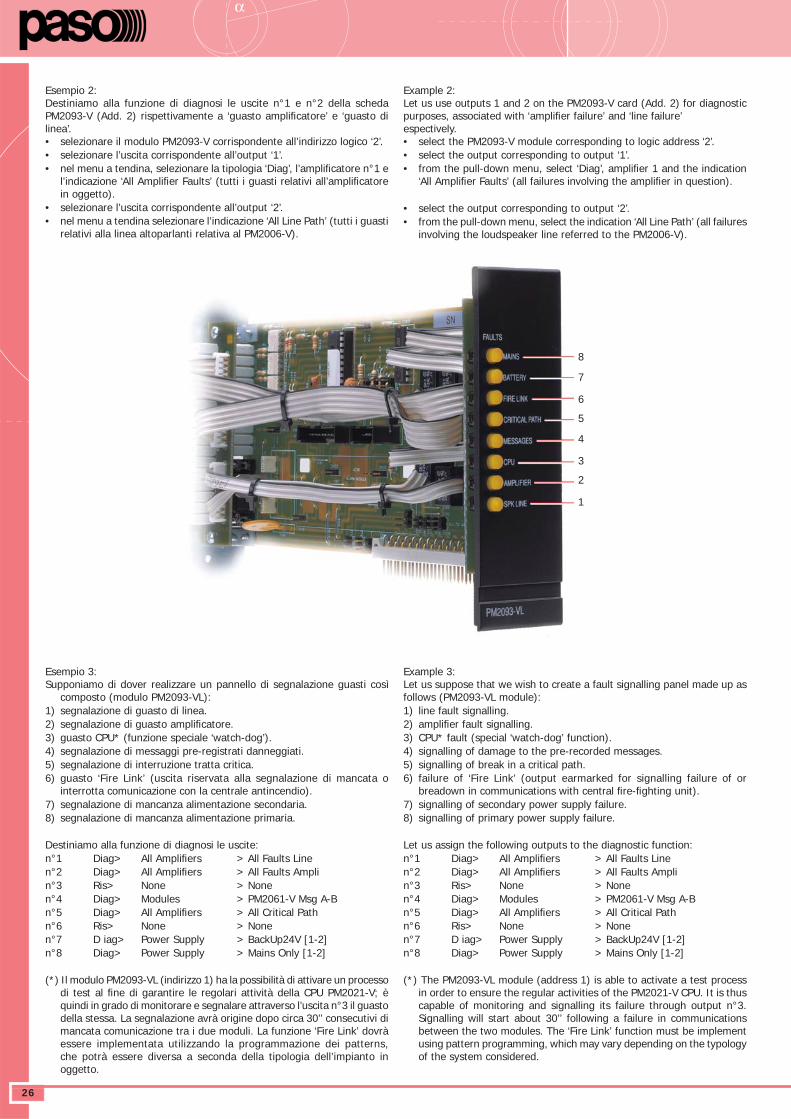
DATASHEETα
26
Esempio 2:Destiniamo alla funzione di diagnosi le uscite n°1 e n°2 della scheda PM2093-V (Add. 2) rispettivamente a ‘guasto amplifi catore’ e ‘guasto di linea’.• selezionare il modulo PM2093-V corrispondente all’indirizzo logico ‘2’.• selezionare l’uscita corrispondente all’output ‘1’.• nel menu a tendina, selezionare la tipologia ‘Diag’, l’amplifi catore n°1 e
l’indicazione ‘All Amplifi er Faults’ (tutti i guasti relativi all’amplifi catore in oggetto).
• selezionare l’uscita corrispondente all’output ‘2’.• nel menu a tendina selezionare l’indicazione ‘All Line Path’ (tutti i guasti
relativi alla linea altoparlanti relativa al PM2006-V).
Esempio 3:Supponiamo di dover realizzare un pannello di segnalazione guasti così
composto (modulo PM2093-VL):1) segnalazione di guasto di linea.2) segnalazione di guasto amplifi catore.3) guasto CPU* (funzione speciale ‘watch-dog’).4) segnalazione di messaggi pre-registrati danneggiati.5) segnalazione di interruzione tratta critica.6) guasto ‘Fire Link’ (uscita riservata alla segnalazione di mancata o
interrotta comunicazione con la centrale antincendio).7) segnalazione di mancanza alimentazione secondaria.8) segnalazione di mancanza alimentazione primaria.
Destiniamo alla funzione di diagnosi le uscite:n°1 Diag> All Amplifi ers > All Faults Linen°2 Diag> All Amplifi ers > All Faults Amplin°3 Ris> None > Nonen°4 Diag> Modules > PM2061-V Msg A-Bn°5 Diag> All Amplifi ers > All Critical Pathn°6 Ris> None > Nonen°7 D iag> Power Supply > BackUp24V [1-2]n°8 Diag> Power Supply > Mains Only [1-2]
(*) Il modulo PM2093-VL (indirizzo 1) ha la possibilità di attivare un processo di test al fi ne di garantire le regolari attività della CPU PM2021-V; è quindi in grado di monitorare e segnalare attraverso l’uscita n°3 il guasto della stessa. La segnalazione avrà origine dopo circa 30’’ consecutivi di mancata comunicazione tra i due moduli. La funzione ‘Fire Link’ dovrà essere implementata utilizzando la programmazione dei patterns, che potrà essere diversa a seconda della tipologia dell’impianto in oggetto.
Example 2:Let us use outputs 1 and 2 on the PM2093-V card (Add. 2) for diagnostic purposes, associated with ‘amplifi er failure’ and ‘line failure’ espectively.• select the PM2093-V module corresponding to logic address ‘2’.• select the output corresponding to output ‘1’.• from the pull-down menu, select ‘Diag’, amplifi er 1 and the indication
‘All Amplifi er Faults’ (all failures involving the amplifi er in question).
• select the output corresponding to output ‘2’.• from the pull-down menu, select the indication ‘All Line Path’ (all failures
involving the loudspeaker line referred to the PM2006-V).
Example 3:Let us suppose that we wish to create a fault signalling panel made up as follows (PM2093-VL module):1) line fault signalling.2) amplifi er fault signalling.3) CPU* fault (special ‘watch-dog’ function).4) signalling of damage to the pre-recorded messages.5) signalling of break in a critical path.6) failure of ‘Fire Link’ (output earmarked for signalling failure of or
breadown in communications with central fi re-fi ghting unit).7) signalling of secondary power supply failure.8) signalling of primary power supply failure.
Let us assign the following outputs to the diagnostic function:n°1 Diag> All Amplifi ers > All Faults Linen°2 Diag> All Amplifi ers > All Faults Amplin°3 Ris> None > Nonen°4 Diag> Modules > PM2061-V Msg A-Bn°5 Diag> All Amplifi ers > All Critical Pathn°6 Ris> None > Nonen°7 D iag> Power Supply > BackUp24V [1-2]n°8 Diag> Power Supply > Mains Only [1-2]
(*) The PM2093-VL module (address 1) is able to activate a test process in order to ensure the regular activities of the PM2021-V CPU. It is thus capable of monitoring and signalling its failure through output n°3. Signalling will start about 30’’ following a failure in communications between the two modules. The ‘Fire Link’ function must be implement using pattern programming, which may vary depending on the typology of the system considered.
8
7
6
5
4
3
2
1
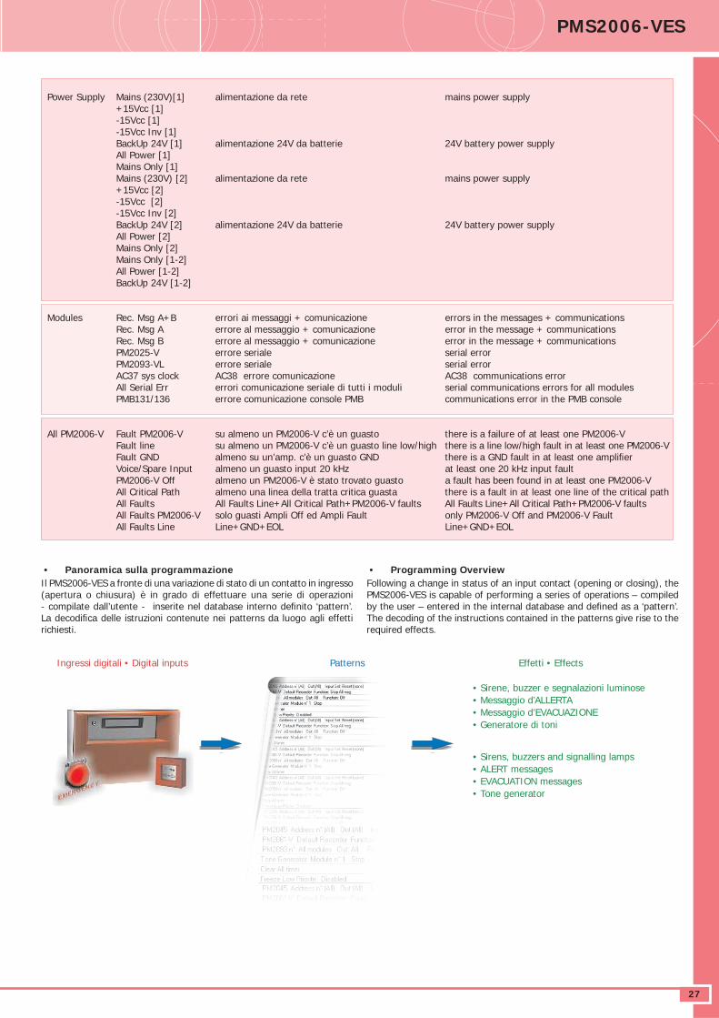
DATASHEET PMS2006-VES
27
Power Supply Mains (230V)[1] alimentazione da rete mains power supply +15Vcc [1] -15Vcc [1] -15Vcc Inv [1] BackUp 24V [1] alimentazione 24V da batterie 24V battery power supply All Power [1] Mains Only [1] Mains (230V) [2] alimentazione da rete mains power supply +15Vcc [2] -15Vcc [2] -15Vcc Inv [2] BackUp 24V [2] alimentazione 24V da batterie 24V battery power supply All Power [2] Mains Only [2] Mains Only [1-2] All Power [1-2] BackUp 24V [1-2]
Modules Rec. Msg A+B errori ai messaggi + comunicazione errors in the messages + communications Rec. Msg A errore al messaggio + comunicazione error in the message + communications Rec. Msg B errore al messaggio + comunicazione error in the message + communications PM2025-V errore seriale serial error PM2093-VL errore seriale serial error AC37 sys clock AC38 errore comunicazione AC38 communications error All Serial Err errori comunicazione seriale di tutti i moduli serial communications errors for all modules PMB131/136 errore comunicazione console PMB communications error in the PMB console
All PM2006-V Fault PM2006-V su almeno un PM2006-V c’è un guasto there is a failure of at least one PM2006-V Fault line su almeno un PM2006-V c’è un guasto line low/high there is a line low/high fault in at least one PM2006-V Fault GND almeno su un’amp. c’è un guasto GND there is a GND fault in at least one amplifi er Voice/Spare Input almeno un guasto input 20 kHz at least one 20 kHz input fault PM2006-V Off almeno un PM2006-V è stato trovato guasto a fault has been found in at least one PM2006-V All Critical Path almeno una linea della tratta critica guasta there is a fault in at least one line of the critical path All Faults All Faults Line+All Critical Path+PM2006-V faults All Faults Line+All Critical Path+PM2006-V faults All Faults PM2006-V solo guasti Ampli Off ed Ampli Fault only PM2006-V Off and PM2006-V Fault All Faults Line Line+GND+EOL Line+GND+EOL
• Panoramica sulla programmazioneIl PMS2006-VES a fronte di una variazione di stato di un contatto in ingresso (apertura o chiusura) è in grado di effettuare una serie di operazioni - compilate dall’utente - inserite nel database interno defi nito ‘pattern’. La decodifi ca delle istruzioni contenute nei patterns da luogo agli effetti richiesti.
• Programming OverviewFollowing a change in status of an input contact (opening or closing), the PMS2006-VES is capable of performing a series of operations – compiled by the user – entered in the internal database and defi ned as a ‘pattern’. The decoding of the instructions contained in the patterns give rise to the required effects.
Ingressi digitali • Digital inputs Patterns Effetti • Effects
• Sirene, buzzer e segnalazioni luminose• Messaggio d’ALLERTA• Messaggio d’EVACUAZIONE• Generatore di toni
• Sirens, buzzers and signalling lamps• ALERT messages• EVACUATION messages• Tone generator
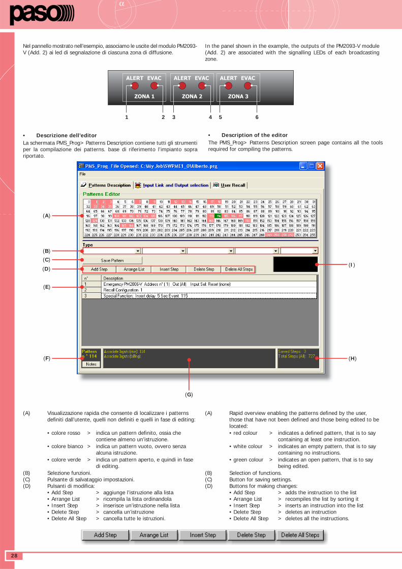
DATASHEETα
28
Nel pannello mostrato nell’esempio, associamo le uscite del modulo PM2093-V (Add. 2) ai led di segnalazione di ciascuna zona di diffusione.
• Descrizione dell’editor La schermata PMS_Prog> Patterns Description contiene tutti gli strumenti per la compilazione dei patterns. base di riferimento l’impianto sopra riportato.
(A) Visualizzazione rapida che consente di localizzare i patterns defi niti dall’utente, quelli non defi niti e quelli in fase di editing:
• colore rosso > indica un pattern defi nito, ossia che contiene almeno un’istruzione.
• colore bianco > indica un pattern vuoto, ovvero senza alcuna istruzione.
• colore verde > indica un pattern aperto, e quindi in fase di editing.
(B) Selezione funzioni.(C) Pulsante di salvataggio impostazioni.(D) Pulsanti di modifi ca: • Add Step > aggiunge l’istruzione alla lista • Arrange List > ricompila la lista ordinandola • Insert Step > inserisce un’istruzione nella lista • Delete Step > cancella un’istruzione • Delete All Step > cancella tutte le istruzioni.
In the panel shown in the example, the outputs of the PM2093-V module (Add. 2) are associated with the signalling LEDs of each broadcasting zone.
• Description of the editorThe PMS_Prog> Patterns Description screen page contains all the tools required for compiling the patterns.
(A) Rapid overview enabling the patterns defi ned by the user, those that have not been defi ned and those being edited to be located:
• red colour > indicates a defi ned pattern, that is to say containing at least one instruction.
• white colour > indicates an empty pattern, that is to say containing no instructions.
• green colour > indicates an open pattern, that is to say being edited.
(B) Selection of functions.(C) Button for saving settings.(D) Buttons for making changes: • Add Step > adds the instruction to the list • Arrange List > recompiles the list by sorting it • Insert Step > inserts an instruction into the list • Delete Step > deletes an instruction • Delete All Step > deletes all the instructions.
ON
RESET
ALERT
ZONA 1
EVAC ALERT
ZONA 2
EVAC ALERT
ZONA 3
EVAC
1 2 3 4 5 6
(A)
(B)
(C)
(D)
(E)
(F)
(G)
(H)
(I)

DATASHEET PMS2006-VES
29
(E) Lista delle istruzioni contenute nel pattern.(F) Indicazione pattern in fase di editing.(G) Indicazione dell’associazione con gli ingressi.(H) Numero di step contenuti nel pattern e indicazione della quantità
di memoria occupata.(I) Indicazione immediata delle caratteristiche del pattern puntato
dal mouse nella fi nestra (A).
• Modifi ca di un pattern esistenteAlla lista di operazioni mostrate a video è possibile aggiungere nuove istruzioni oppure effettuare inserimenti o cancellazioni in qualsiasi punto del listato. Il componimento di nuove istruzioni, sia che debbano trovare collocazione in fondo alla lista piuttosto che essere inserite in posizioni diverse, avverrà sempre utilizzando i menu guidati a tendina presenti nell’editor. Dopo aver composto l’istruzione da inserire nella lista, posizionare il mouse sulla riga immediatamente successiva (nel nostro esempio la riga n°3) e cliccare su < Insert Step >: nell’elenco di operazioni verrà aggiunta la nuova istruzione.
• Cancellazione di un patternUn pattern può dirsi ‘cancellato’ quando non contiene nessuna istruzione al suo interno. Per eliminare una singola riga di programma, è suffi ciente selezionare quest’ultima e cliccare su < Delete Step >.L’eliminazione di tutti i passi d’istruzione contenuti in un record è possibile utilizzando il comando < Delete All Steps >; il pattern verrà aggiornato automaticamente senza bisogno di premere < Save Pattern >. Il fondo della casella relativa al record diventerà bianco.
Nota:Si ricorda che al termine delle operazioni è necessario cliccare sul pulsante < Save Pattern > per salvare tutte le istruzioni impostate.
(E) List of instructions contained in the pattern.(F) Indication of pattern being edited.(G) Indication of association with inputs.(H) Number of steps contained in the pattern and indication of the
amount of memory occupied.(I) Immediate indication of the features of the pattern at which the
mouse is pointing in the window (A).
• Changing an existing patternIt is possible to add new instructions to the list shown on screen, or to insert or delete them into or from any point of the list. New instructions, whether they are meant to be added at the end of the list or to be inserted here and there, will always be composed using the guided pull-down menus present in the editor. After composing the instruction to be inserted into the list, position the mouse on the line immediately following the position in question (in our example, line n° 3) and click on < Insert Step >: the new instruction will be added to the list of operations.
• Deleting a patternA pattern can be said to have been ‘deleted’ when it does not contain any instructions inside it. To eliminate a single line of the program, it is suffi cient to select the line and click on < Delete Step >.It is possible to eliminate all the instruction steps contained in a record using the < Delete All Steps > command; the pattern will be up-dated automatically with no need to press < Save Pattern >. The background in the box for the record will turn white.
Note:It should be remembered that upon completion of the operations it is necessary to click on the < Save Pattern > button to save all the instructions entered.
Al termine delle modifi che, sarà suffi ciente cliccare su <Arrange List> perchè l’ordine progressivo delle istruzioni venga aggiornato automaticamente.
Upon completion of the changes, it will be suffi cient to click on <Arrange List> and the progressive order of the instructions will be automatically up-dated.
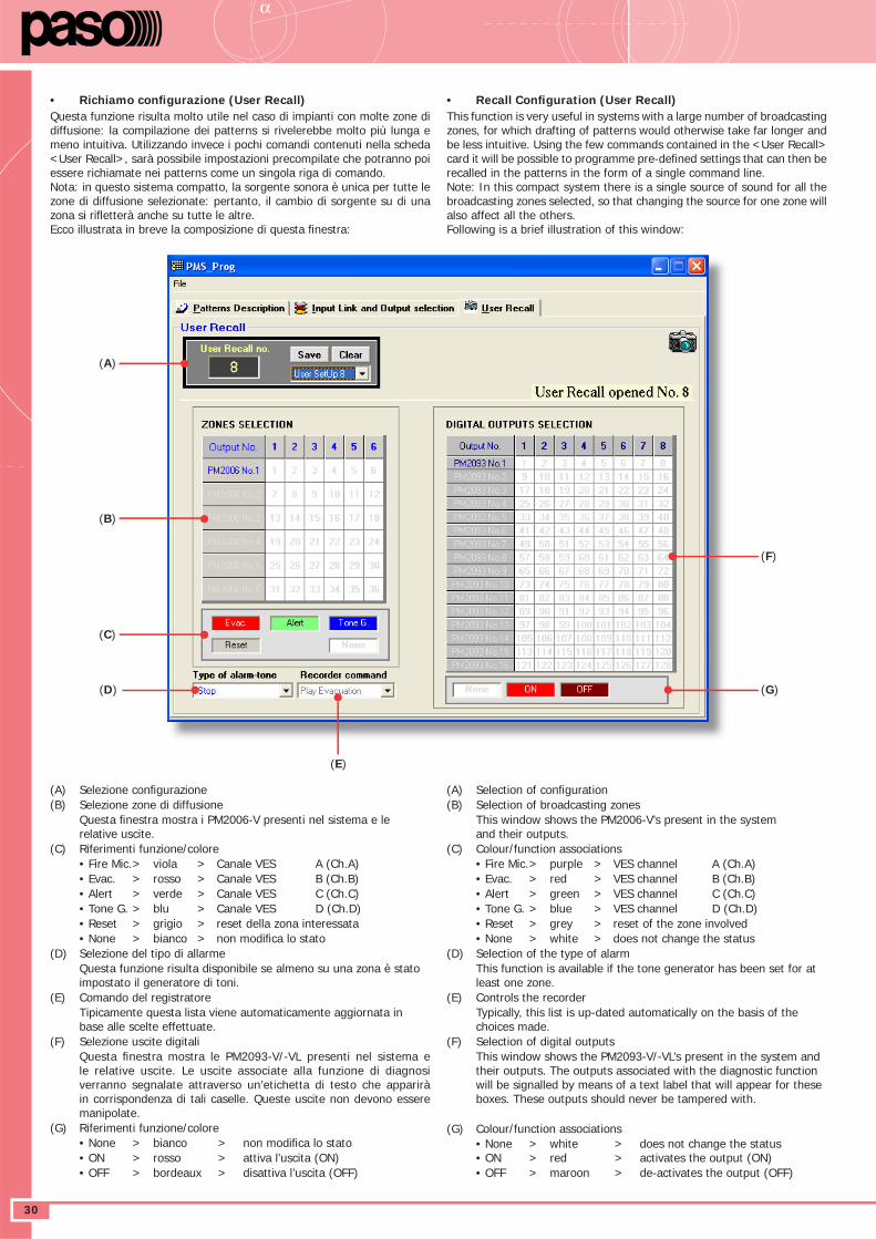
DATASHEETα
30
• Richiamo confi gurazione (User Recall)Questa funzione risulta molto utile nel caso di impianti con molte zone di diffusione: la compilazione dei patterns si rivelerebbe molto più lunga e meno intuitiva. Utilizzando invece i pochi comandi contenuti nella scheda <User Recall>, sarà possibile impostazioni precompilate che potranno poi essere richiamate nei patterns come un singola riga di comando. Nota: in questo sistema compatto, la sorgente sonora è unica per tutte le zone di diffusione selezionate: pertanto, il cambio di sorgente su di una zona si rifl etterà anche su tutte le altre.Ecco illustrata in breve la composizione di questa fi nestra:
(A) Selezione confi gurazione(B) Selezione zone di diffusione Questa fi nestra mostra i PM2006-V presenti nel sistema e le
relative uscite.(C) Riferimenti funzione/colore • Fire Mic. > viola > Canale VES A (Ch.A) • Evac. > rosso > Canale VES B (Ch.B) • Alert > verde > Canale VES C (Ch.C) • Tone G. > blu > Canale VES D (Ch.D) • Reset > grigio > reset della zona interessata • None > bianco > non modifi ca lo stato(D) Selezione del tipo di allarme Questa funzione risulta disponibile se almeno su una zona è stato
impostato il generatore di toni.(E) Comando del registratore Tipicamente questa lista viene automaticamente aggiornata in
base alle scelte effettuate.(F) Selezione uscite digitali Questa fi nestra mostra le PM2093-V/-VL presenti nel sistema e
le relative uscite. Le uscite associate alla funzione di diagnosi verranno segnalate attraverso un’etichetta di testo che apparirà in corrispondenza di tali caselle. Queste uscite non devono essere manipolate.
(G) Riferimenti funzione/colore • None > bianco > non modifi ca lo stato • ON > rosso > attiva l’uscita (ON) • OFF > bordeaux > disattiva l’uscita (OFF)
• Recall Confi guration (User Recall)This function is very useful in systems with a large number of broadcasting zones, for which drafting of patterns would otherwise take far longer and be less intuitive. Using the few commands contained in the <User Recall> card it will be possible to programme pre-defi ned settings that can then be recalled in the patterns in the form of a single command line. Note: In this compact system there is a single source of sound for all the broadcasting zones selected, so that changing the source for one zone will also affect all the others.Following is a brief illustration of this window:
(A) Selection of confi guration(B) Selection of broadcasting zones This window shows the PM2006-V’s present in the system
and their outputs.(C) Colour/function associations • Fire Mic. > purple > VES channel A (Ch.A) • Evac. > red > VES channel B (Ch.B) • Alert > green > VES channel C (Ch.C) • Tone G. > blue > VES channel D (Ch.D) • Reset > grey > reset of the zone involved • None > white > does not change the status(D) Selection of the type of alarm This function is available if the tone generator has been set for at
least one zone.(E) Controls the recorder Typically, this list is up-dated automatically on the basis of the
choices made.(F) Selection of digital outputs This window shows the PM2093-V/-VL’s present in the system and
their outputs. The outputs associated with the diagnostic function will be signalled by means of a text label that will appear for these boxes. These outputs should never be tampered with.
(G) Colour/function associations • None > white > does not change the status
• ON > red > activates the output (ON) • OFF > maroon > de-activates the output (OFF)
(A)
(B)
(C)
(D)
(F)
(G)
(E)
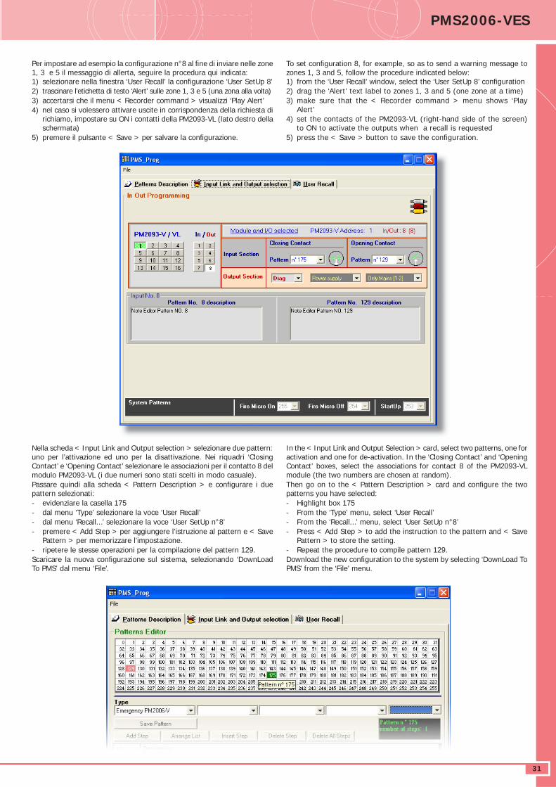
DATASHEET PMS2006-VES
31
Per impostare ad esempio la confi gurazione n°8 al fi ne di inviare nelle zone 1, 3 e 5 il messaggio di allerta, seguire la procedura qui indicata:1) selezionare nella fi nestra ‘User Recall’ la confi gurazione ‘User SetUp 8’2) trascinare l’etichetta di testo ‘Alert’ sulle zone 1, 3 e 5 (una zona alla volta)3) accertarsi che il menu < Recorder command > visualizzi ‘Play Alert’4) nel caso si volessero attivare uscite in corrispondenza della richiesta di
richiamo, impostare su ON i contatti della PM2093-VL (lato destro della schermata)
5) premere il pulsante < Save > per salvare la confi gurazione.
Nella scheda < Input Link and Output selection > selezionare due pattern: uno per l’attivazione ed uno per la disattivazione. Nei riquadri ‘Closing Contact’ e ‘Opening Contact’ selezionare le associazioni per il contatto 8 del modulo PM2093-VL (i due numeri sono stati scelti in modo casuale).Passare quindi alla scheda < Pattern Description > e confi gurare i due pattern selezionati:- evidenziare la casella 175- dal menu ‘Type’ selezionare la voce ‘User Recall’ - dal menu ‘Recall...’ selezionare la voce ‘User SetUp n°8’- premere < Add Step > per aggiungere l’istruzione al pattern e < Save
Pattern > per memorizzare l’impostazione.- ripetere le stesse operazioni per la compilazione del pattern 129.Scaricare la nuova confi gurazione sul sistema, selezionando ‘DownLoad To PMS’ dal menu ‘File’.
To set confi guration 8, for example, so as to send a warning message to zones 1, 3 and 5, follow the procedure indicated below:1) from the ‘User Recall’ window, select the ‘User SetUp 8’ confi guration2) drag the ‘Alert’ text label to zones 1, 3 and 5 (one zone at a time)3) make sure that the < Recorder command > menu shows ‘Play
Alert’4) set the contacts of the PM2093-VL (right-hand side of the screen)
to ON to activate the outputs when a recall is requested5) press the < Save > button to save the confi guration.
In the < Input Link and Output Selection > card, select two patterns, one for activation and one for de-activation. In the ‘Closing Contact’ and ‘Opening Contact’ boxes, select the associations for contact 8 of the PM2093-VL module (the two numbers are chosen at random).Then go on to the < Pattern Description > card and confi gure the two patterns you have selected:- Highlight box 175- From the ‘Type’ menu, select ‘User Recall’ - From the ‘Recall...’ menu, select ‘User SetUp n°8’- Press < Add Step > to add the instruction to the pattern and < Save
Pattern > to store the setting.- Repeat the procedure to compile pattern 129.Download the new confi guration to the system by selecting ‘DownLoad To PMS’ from the ‘File’ menu.
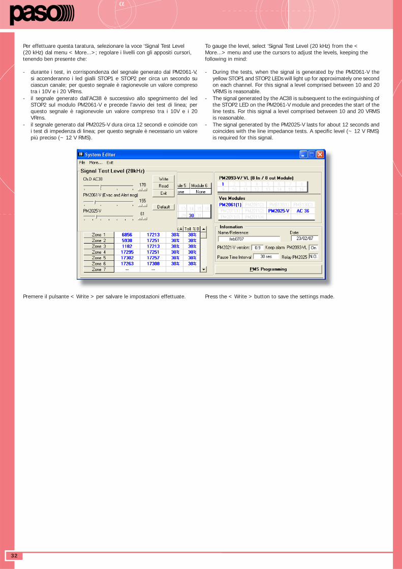
DATASHEETα
32
Per effettuare questa taratura, selezionare la voce ‘Signal Test Level (20 kHz) dal menu < More...>; regolare i livelli con gli appositi cursori, tenendo ben presente che:
- durante i test, in corrispondenza del segnale generato dal PM2061-V, si accenderanno i led gialli STOP1 e STOP2 per circa un secondo su ciascun canale; per questo segnale è ragionevole un valore compreso tra i 10V e i 20 VRms.
- il segnale generato dall’AC38 è successivo allo spegnimento del led STOP2 sul modulo PM2061-V e precede l’avvio dei test di linea; per questo segnale è ragionevole un valore compreso tra i 10V e i 20 VRms.
- il segnale generato dal PM2025-V dura circa 12 secondi e coincide con i test di impedenza di linea; per questo segnale è necessario un valore più preciso (~ 12 V RMS).
Premere il pulsante < Write > per salvare le impostazioni effettuate.
To gauge the level, select ‘Signal Test Level (20 kHz) from the < More...> menu and use the cursors to adjust the levels, keeping the following in mind:
- During the tests, when the signal is generated by the PM2061-V the yellow STOP1 and STOP2 LEDs will light up for approximately one second on each channel. For this signal a level comprised between 10 and 20 VRMS is reasonable.
- The signal generated by the AC38 is subsequent to the extinguishing of the STOP2 LED on the PM2061-V module and precedes the start of the line tests. For this signal a level comprised between 10 and 20 VRMS is reasonable.
- The signal generated by the PM2025-V lasts for about 12 seconds and coincides with the line impedance tests. A specifi c level (~ 12 V RMS) is required for this signal.
Press the < Write > button to save the settings made.
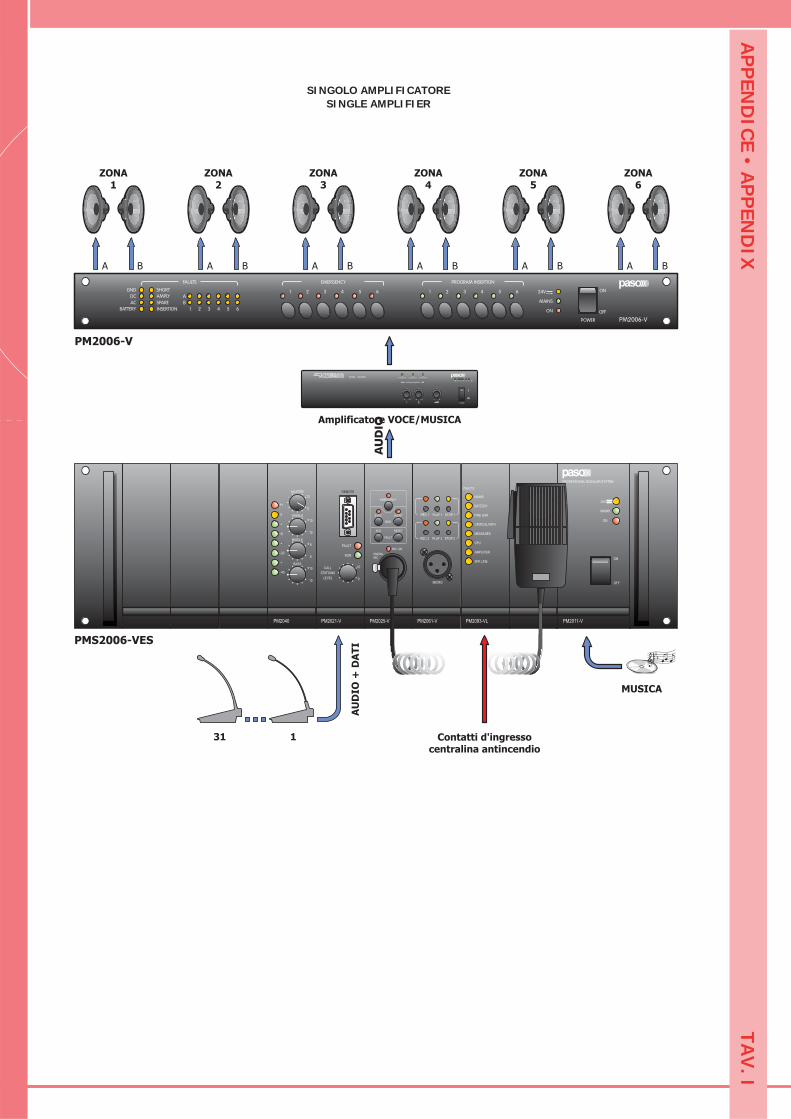
AP
PEN
DIC
E • AP
PEN
DIX
TAV
. I
SINGOLO AMPLIFICATORESINGLE AMPLIFIER
PM2093-VL
MAINS
BATTERY
FIRE LINK
CRITICAL PATH
MESSAGES
CPU
AMPLIFIER
SPK LINE
FAULTS
BASS
10+
10
10
0
MASTER
TREBLE
10
+10
6+
6
MIDDLE
40-
1+
0
6-
20-
PM2040
10
0
FAULT
REMOTE
STATIONS
LEVEL
CALL
RUN
PM2021-V PM2061-V
REC 1 PLAY 1 STOP 1
REC 2 PLAY 2 STOP 2
MICRO
PROFESSIONAL MODULAR SYSTEM
ON
MAINS
24V
OFF
ON
PM2011-V
MIC. ON
EMERG.MIC.
FAULT
ACK RESET
ALERTEVAC
EMERGENCY
MSG.
PM2025-V
PU
SH
GND
DC
AC
BATTERY
SHORT
AMPLY
SPARE
INSERTION
A
B
POWER
ON
OFFON
MAINS
24V
PM2006-V
1 2 3 4 5 6
FAULTS
1 2 3 4 5 6
EMERGENCY
1 2 3 4 5 6
PROGRAM INSERTION
ON
PROGRAM INSERTION
POWER AMPLIFIER
MUSICA
Contatti d'ingressocentralina antincendio
AU
DIO
+D
AT
I
ZONA1
A B
Amplificatore VOCE/MUSICA
AU
DIO
PM2006-V
PMS2006-VES
131
ZONA6
A B
ZONA3
A B
ZONA4
A B
ZONA5
A B
ZONA2
A B
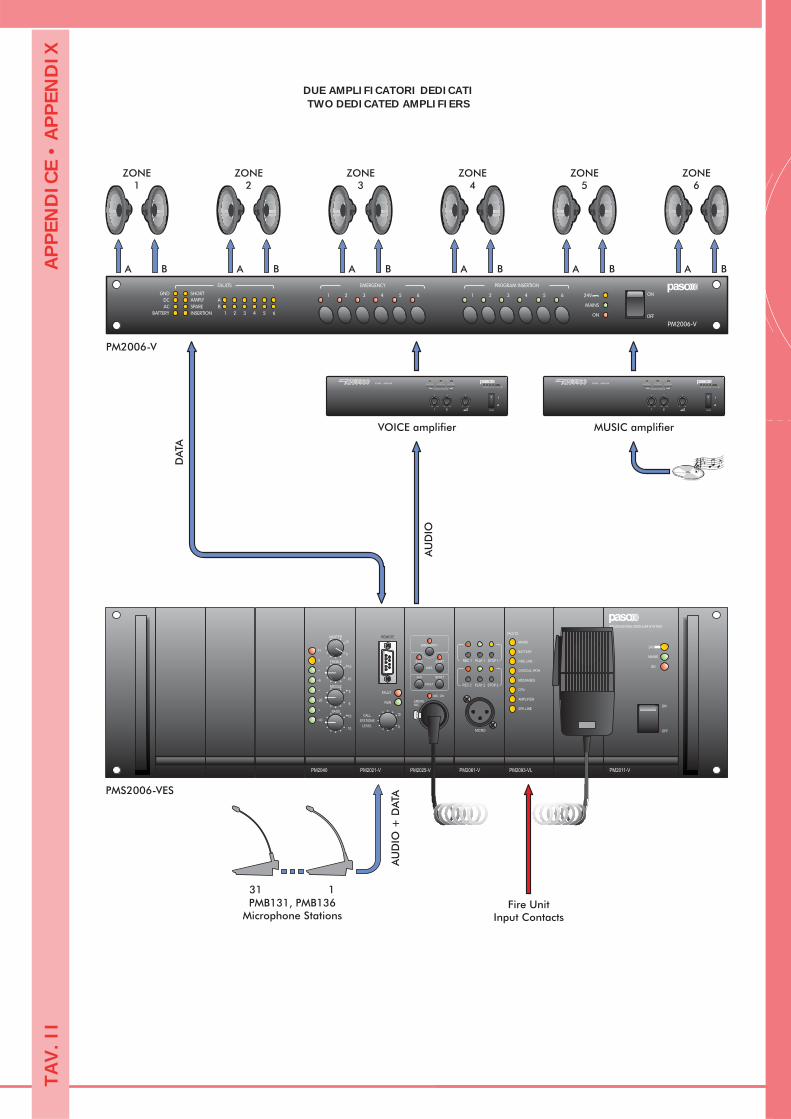
AP
PEN
DIC
E •
AP
PEN
DIX
TAV
. II
DUE AMPLIFICATORI DEDICATITWO DEDICATED AMPLIFIERS
PM2093-VL
MAINS
BATTERY
FIRE LINK
CRITICAL PATH
MESSAGES
CPU
AMPLIFIER
SPK LINE
FAULTS
BASS
10+
10
10
0
MASTER
TREBLE
10
+10
6+
6
MIDDLE
40-
1+
0
6-
20-
PM2040
10
0
FAULT
REMOTE
STATIONS
LEVEL
CALL
RUN
PM2021-V PM2061-V
REC 1 PLAY 1 STOP 1
REC 2 PLAY 2 STOP 2
MICRO
PROFESSIONAL MODULAR SYSTEM
ON
MAINS
24V
OFF
ON
PM2011-V
MIC. ON
EMERG.MIC.
FAULT
ACK RESET
ALERTEVAC
EMERGENCY
MSG.
PM2025-V
PU
SH
GND
DC
AC
BATTERY
SHORT
AMPLY
SPARE
INSERTION
A
B
ON
OFFON
MAINS
24V
PM2006-V
1 2 3 4 5 6
FAULTS
1 2 3 4 5 6
EMERGENCY
1 2 3 4 5 6
PROGRAM INSERTION
Fire UnitInput Contacts
AU
DIO
+ D
ATA
ON
PROGRAM INSERTION
POWER AMPLIFIER
VOICE amplifierA
UD
IO
DA
TA
PM2006-V
PMS2006-VES
131
ZONE6
A B
ZONE5
A B
ZONE4
A B
ZONE3
A B
ZONE2
A B
ZONE1
A B
PMB131, PMB136Microphone Stations
ON
PROGRAM INSERTION
POWER AMPLIFIER
MUSIC amplifier
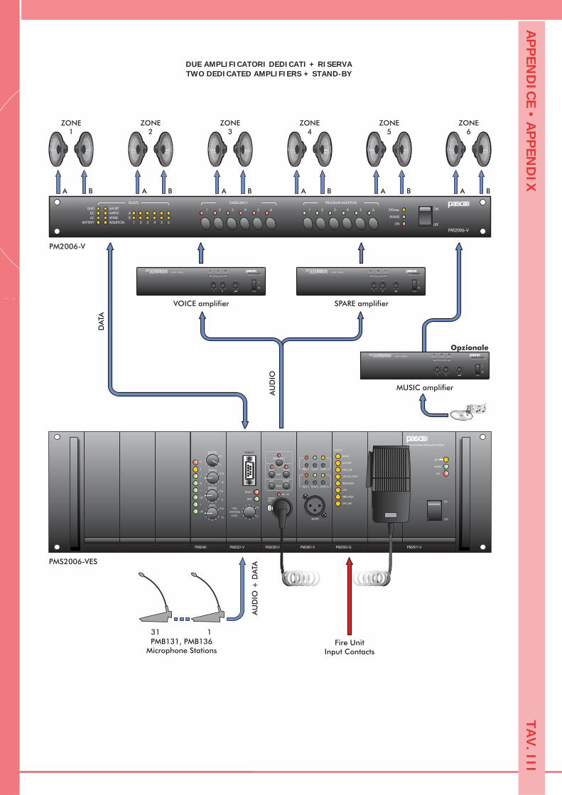
AP
PEN
DIC
E • AP
PEN
DIX
TAV
. III
DUE AMPLIFICATORI DEDICATI + RISERVATWO DEDICATED AMPLIFIERS + STAND-BY
PM2093-VL
MAINS
BATTERY
FIRE LINK
CRITICAL PATH
MESSAGES
CPU
AMPLIFIER
SPK LINE
FAULTS
BASS
10+
10
10
0
MASTER
TREBLE
10
+10
6+
6
MIDDLE
40-
1+
0
6-
20-
PM2040
10
0
FAULT
REMOTE
STATIONS
LEVEL
CALL
RUN
PM2021-V PM2061-V
REC 1 PLAY 1 STOP 1
REC 2 PLAY 2 STOP 2
MICRO
PROFESSIONAL MODULAR SYSTEM
ON
MAINS
24V
OFF
ON
PM2011-V
MIC. ON
EMERG.MIC.
FAULT
ACK RESET
ALERTEVAC
EMERGENCY
MSG.
PM2025-V
PU
SH
GND
DC
AC
BATTERY
SHORT
AMPLY
SPARE
INSERTION
A
B
ON
OFFON
MAINS
24V
PM2006-V
1 2 3 4 5 6
FAULTS
1 2 3 4 5 6
EMERGENCY
1 2 3 4 5 6
PROGRAM INSERTION
ON
PROGRAM INSERTION
POWER AMPLIFIER
Fire UnitInput Contacts
AU
DIO
+ D
ATA
VOICE amplifier
Opzionale
AU
DIO
DA
TA
PM2006-V
PMS2006-VES
131
ZONE6
A B
ZONE5
A B
ZONE4
A B
ZONE3
A B
ZONE2
A B
ZONE1
A B
PMB131, PMB136Microphone Stations
ON
PROGRAM INSERTION
POWER AMPLIFIER
SPARE amplifier
ON
PROGRAM INSERTION
POWER AMPLIFIER
MUSIC amplifier
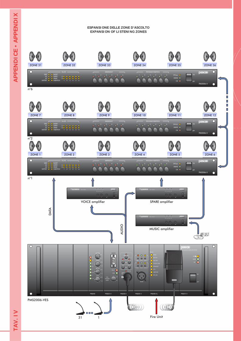
AP
PEN
DIC
E •
AP
PEN
DIX
TAV
. IV
ESPANSIONE DELLE ZONE D’ASCOLTOEXPANSION OF LISTENING ZONES
PM2093-VL
MAINS
BATTERY
FIRE LINK
CRITICAL PATH
MESSAGES
CPU
AMPLIFIER
SPK LINE
FAULTS
BASS
10+
10
10
0
MASTER
TREBLE
10
+10
6+
6
MIDDLE
40-
1+
0
6-
20-
PM2040
10
0
FAULT
REMOTE
STATIONS
LEVEL
CALL
RUN
PM2021-V PM2061-V
REC 1 PLAY 1 STOP 1
REC 2 PLAY 2 STOP 2
MICRO
PROFESSIONAL MODULAR SYSTEM
ON
MAINS
24V
OFF
ON
PM2011-V
MIC. ON
EMERG.MIC.
FAULT
ACK RESET
ALERTEVAC
EMERGENCY
MSG.
PM2025-V
PU
SH
GND
DC
AC
BATTERY
SHORT
AMPLY
SPARE
INSERTION
A
B
ON
OFFON
MAINS
24V
PM2006-V
1 2 3 4 5 6
FAULTS
1 2 3 4 5 6
EMERGENCY
1 2 3 4 5 6
PROGRAM INSERTION
ON
PROGRAM INSERTION
POWER AMPLIFIER
Fire Unit
VOICE amplifier
AU
DIO
DA
TA
n°1
PMS2006-VES
131
ON
PROGRAM INSERTION
POWER AMPLIFIER
SPARE amplifier
ON
PROGRAM INSERTION
POWER AMPLIFIER
MUSIC amplifier
ZONE 1 ZONE 2 ZONE 3 ZONE 4 ZONE 5 ZONE 6
GND
DC
AC
BATTERY
SHORT
AMPLY
SPARE
INSERTION
A
B
ON
OFFON
MAINS
24V
PM2006-V
1 2 3 4 5 6
FAULTS
1 2 3 4 5 6
EMERGENCY
1 2 3 4 5 6
PROGRAM INSERTION
ZONE 7 ZONE 8 ZONE 9 ZONE 10 ZONE 11 ZONE 12
GND
DC
AC
BATTERY
SHORT
AMPLY
SPARE
INSERTION
A
B
ON
OFFON
MAINS
24V
PM2006-V
1 2 3 4 5 6
FAULTS
1 2 3 4 5 6
EMERGENCY
1 2 3 4 5 6
PROGRAM INSERTION
ZONE 31 ZONE 32 ZONE 33 ZONE 34 ZONE 35 ZONE 36
n°2
n°6
Via Mecenate, 90 - 20138 MILANO - ITALIATEL. +39-02-580 77 1 (15 linee r.a.) - FAX +39-02-580 77 277
http://www.paso.it - UDT - 04/07 - 11/646
S.p.A
Alla fi ne della sua vita utile il prodotto non deve essere smaltito insieme ai rifi uti urbani, ma deve essere consegnato presso gli appositi centri di raccolta differenziata predisposti dalla Vostra amministrazione comunale, oppure presso i rivenditori che forniscono questo servizio. Smaltire separatamente un rifi uto elettrico e/o elettronico (RAEE) consente di evitare possibili conseguenze negative per l’ambiente e per la salute derivanti da un suo smaltimento inadeguato e permette di recuperare i materiali di cui è composto al fi ne di ottenere un importante risparmio di energia e di risorse. Su ciascun prodotto è riportato a questo scopo il marchio del contenitore di spazzatura barrato.
!Avvertenze per lo smaltimento di questo prodotto ai sensi della Direttiva Europea 2002/96/EC !
Important information for disposal of the product in accordance with EC Directive 2002/96/EC
This product must not be disposed of as urban waste at the end of its working life. It must be taken to a special waste collection centre licensed by the local authorities or to a dealer providing this service. Separate disposal of electric and/or electronic equipment (WEEE) will avoid possible negative consequences for the environment and for health resulting from inappropriate disposal, and will enable the constituent materials to be recovered, with signifi cant savings in energy and resources. As
a reminder of the need to dispose of this equipment separately, the product is marked with a crossed-out wheeled dustbin.
PASO S.p.A declina ogni responsabilità per danni a cose e/o persone derivanti dall’uso non corretto dell’apparecchio o da procedure non rispondenti a quanto riportato sul presente libretto. Nel continuo intento di migliorare i propri prodotti, la PASO S.p.A. si riserva il diritto di apportare modifi che ai disegni e alle caratteristiche tecniche in qualsiasi momento e senza alcun preavviso.
PASO S.p.A will not accept any liability for damage to property and/or persons arising out of incorrect use of the equipment or of procedures that do not comply with the instructions provided in this booklet. PASO S.p.A. strive to improve their products continuously, and therefore reserve the right to make changes to the drawings and technical specifi cations at any time and without notice.
WARRANTYThis product is warranted to be free from defects in raw materials and assembly. The warranty period is governed by the applicable provisions of law. Paso will repair the product covered by this warranty free of charge if it is faulty, provided the defect has occurred during normal use. The warranty does not cover products that are improperly used or installed, mechanically damaged or damaged by liquids or the weather. If the product is found to be faulty, it must be sent to Paso free of charges for shipment and return. This warranty does not include any others, either explicit or implicit, and does not cover consequential damage to property or personal injury. For further information concerning the warranty contact your local PASO distributor.
Important! Should the user wish to avail himself of servicing under the warranty, he must provide evidence of the purchase (invoice or receipt). The user shall also indicate the date of purchase, model and serial number indicated on the equipment. For this reason, you should complete the box below as a reminder of the data required.
Tutti gli apparecchi PASO sono costruiti nel rispetto delle più severe normative internazionali di sicurezza ed in ottemperanza ai requisiti della Comunità Europea. Per un corretto ed effi cace uso dell’apparecchio è importante prendere conoscenza di tutte le caratteristiche leggendo attentamente le presenti istruzioni ed in particolare le note di sicurezza.
All PASO equipment is manufactured in accordance with the most stringent international safety standards and in compliance with European Community requisites. In order to use the equipment correctly and effectively, it is important to be aware of all its characteristics by reading these instructions and in particular the safety notes carefully.
GARANZIAQuesto prodotto è garantito esente da difetti nelle sue materie prime e nel suo montaggio; il periodo di garanzia è regolamentato dalle norme vigenti. La Paso riparerà gratuitamente il prodotto difettoso qui garantito se il difetto risulterà essersi verifi cato durante l’uso normale; la garanzia non si estende quindi a prodotti usati ed installati in modo errato, danneggiati meccanicamente, danneggiati da liquidi o da agenti atmosferici. Il prodotto, risultato difettoso, dovrà essere inviato alla Paso franco di spese di spedizione e ritorno. Questa garanzia non ne comprende altre, esplicite od implicite, e non comprende danni o incidenti conseguenti a persone o cose. Contattare i distributori PASO della zona per maggiori informazioni sulla garanzia.
Importante! L’utente ha la responsabilità di produrre una prova d’acquisto (fattura o ricevuta) se vuole servirsi dell’assistenza coperta da garanzia. Dovrà inoltre fornire data di acquisto, modello e numero di serie riportati sull’apparecchio; a questo scopo, compilare come promemoria dei dati richiesti lo spazio qui sotto.
MODELLO / MODEL: .............................................................................................................................................................................................
NUMERO DI SERIE / SERIAL NUMBER: ..................................................................................................................................................................
DATA D’ACQUISTO / PURCHASE DATE: ..................................................................................................................................................................
Questo prodotto è conforme alle Direttive della Comunità Europea sotto le quali lo stesso ricade.
This product is in keeping with the relevant European Community Directives.