LUX : A Liquid Xenon Dark Matter Detector Masahiro Morii Harvard University August 24, 2010 1.
Upload
inoxent-khanCategory
view
226download
7
Control system
Automatic street light control system using PI controller
Aroosa
Sheher
Sidra Ali
Mrayam
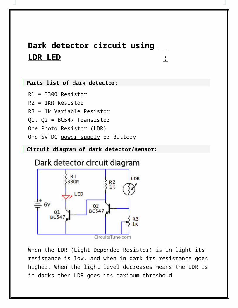
Dark detector circuit using LDR
LED :
Parts list of dark detector:
R1 = 330Ω ResistorR2 = 1KΩ ResistorR3 = 1k Variable ResistorQ1, Q2 = BC547 TransistorOne Photo Resistor (LDR)One 5V DC power supply or Battery
Circuit diagram of dark detector/sensor:
When the LDR (Light Depended Resistor) is in light its resistance is low, and when in dark its resistance goes higher. When the light level decreases means the LDR is in darks then LDR goes its maximum threshold resistance, then the circuit automatically switches on the LED. Here I used a 1K variable resistor as R3 to adjust the dark/light sensitivity of the circuit.
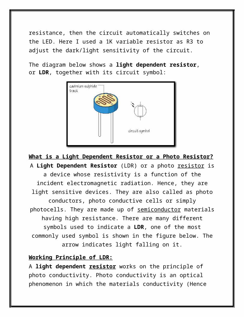
The diagram below shows a light dependent resistor, or LDR, together with its circuit symbol:
What is a Light Dependent Resistor or a Photo Resistor?A Light Dependent Resistor (LDR) or a photo resistor is a device whose resistivity
is a function of the incident electromagnetic radiation. Hence, they are light sensitive devices. They are also called as photo conductors, photo conductive cells
or simply photocells. They are made up of semiconductor materials having high resistance. There are many different symbols used to indicate a LDR, one of the most commonly used symbol is shown in the figure below. The arrow indicates
light falling on it.
Working Principle of LDR:A light dependent resistor works on the principle of photo conductivity. Photo conductivity is an optical phenomenon in which the materials conductivity (Hence resistivity) reduces when light is absorbed by the material.
When light falls i.e. when the photons fall on the device, the electrons in the valence band of the semiconductor material are excited to the conduction band. These photons in the incident light should have energy greater than the band gap of the semiconductor material to make the electrons jump from the valence band
to the conduction band. Hence when light having enough energy is incident on the device more & more electrons are excited to the conduction band which
results in large number of charge carriers. The result of this process is more and
more current starts flowing and hence it is said that the resistance of the device has decreased.This is the most common working principle of LDR
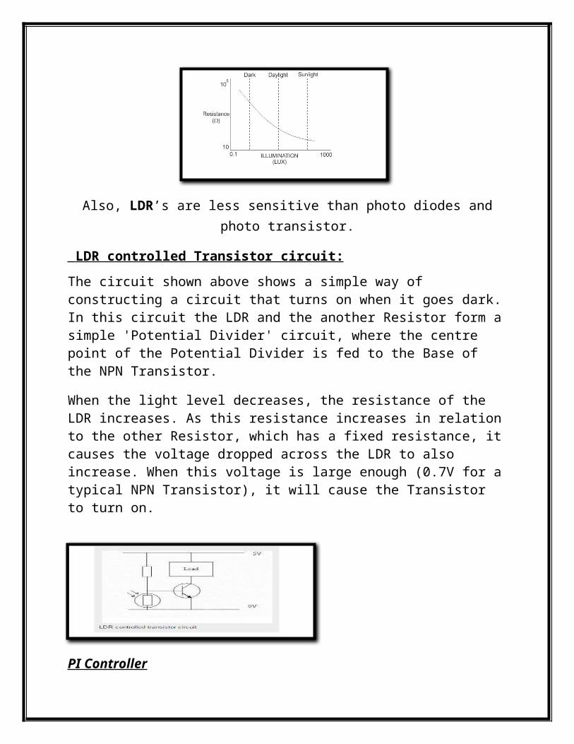
Characteristics of LDR:LDR’s are light dependent devices whose resistance decreases when light falls on them and increases in the dark. When a light dependent resistor is kept in dark, its resistance is very high. This resistance is called as dark resistance. It can be as high as 1012 Ω. And if the device is allowed to absorb light its resistance will decrease drastically. If a constant voltage is applied to it and intensity of light is increased the current starts increasing. Figure below shows resistance vs. illumination curve for a particular LDR.
Also, LDR’s are less sensitive than photo diodes and photo transistor.
LDR controlled Transistor circuit:
The circuit shown above shows a simple way of constructing a circuit that turns on when it goes dark. In this circuit the LDR and the another Resistor form a simple 'Potential Divider' circuit, where the centre point of the Potential Divider is fed to the Base of the NPN Transistor.
When the light level decreases, the resistance of the LDR increases. As this resistance increases in relation to the other Resistor, which has a fixed resistance, it causes the voltage dropped across the LDR to also increase. When this voltage is large enough (0.7V for a typical NPN Transistor), it will cause the Transistor to turn on.
PI Controller
The Proportional-Integral (PI) algorithm computes and transmits a controller output (CO) signal every sample time, T, to the final control element (e.g., valve, variable speed pump). The computed CO from the PI algorithm is influenced by the controller tuning parameters and the controller error, e (t)
Integral action enables PI controllers to eliminate offset, a major weakness of a P-only controller.
PI controllers provide a balance of complexity and capability that makes them by far the most widely used algorithm in process control applications.
Pi controller are use to increase the speed of the response and also to eliminate the steady state error
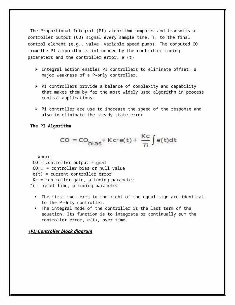
The PI Algorithm
Where: CO = controller output signal CObias = controller bias or null value e(t) = current controller error Kc = controller gain, a tuning parameter Ti = reset time, a tuning parameter
The first two terms to the right of the equal sign are identical to the P-Only controller.
The integral mode of the controller is the last term of the equation. Its function is to integrate or continually sum the controller error, e(t), over time.
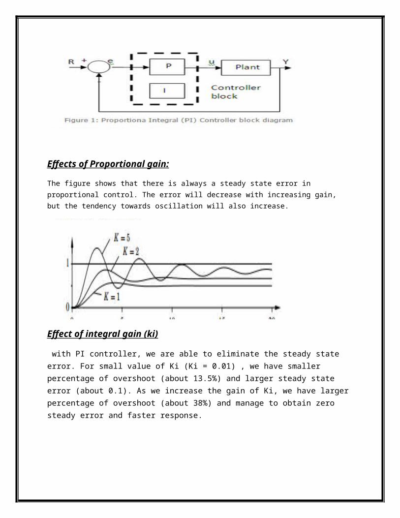
( PI) Controller block diagram
Effects of Proportional gain:
The figure shows that there is always a steady state error in proportional control. The error will decrease with increasing gain, but the tendency towards oscillation will also increase.
Effect of integral gain (ki)
with PI controller, we are able to eliminate the steady state error. For small value of Ki (Ki = 0.01) , we have smaller percentage of overshoot (about 13.5%) and larger steady state error (about 0.1). As we increase the gain of Ki, we have larger percentage of overshoot (about 38%) and manage to obtain zero steady error and faster response.
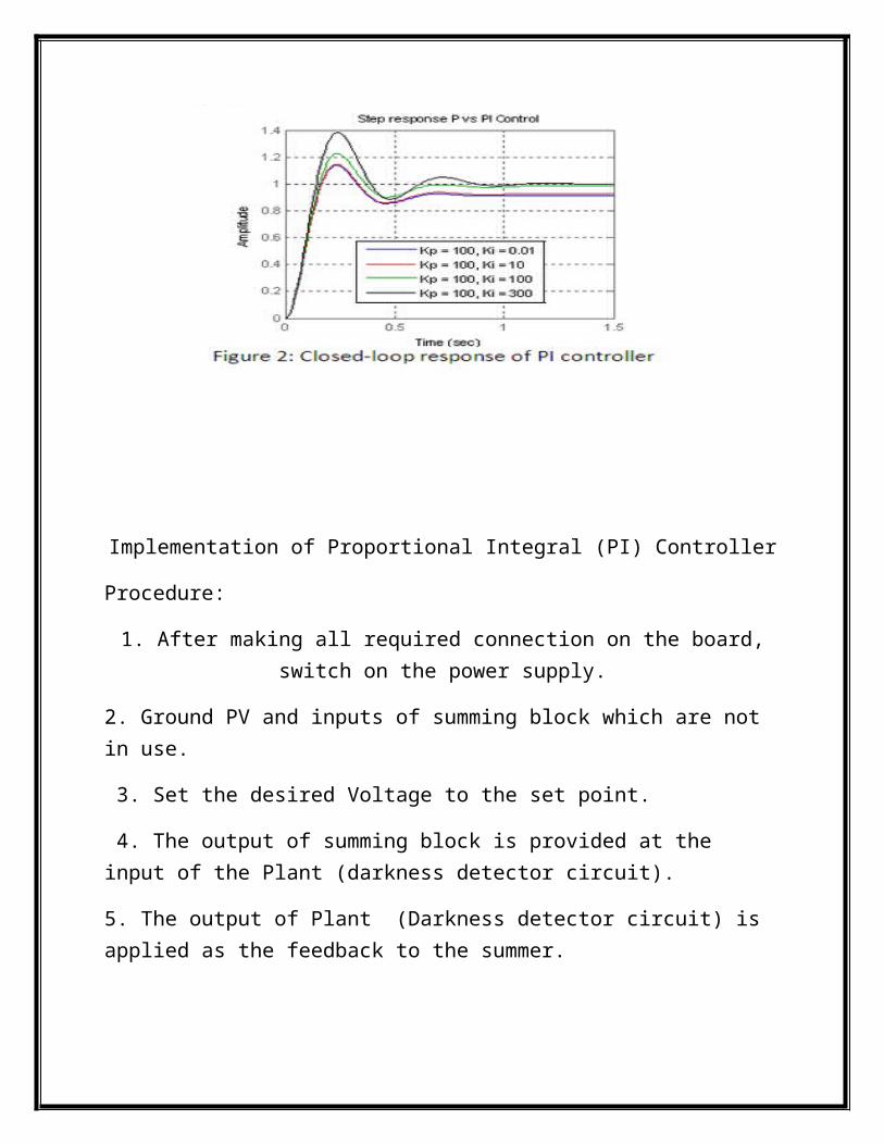
Implementation of Proportional Integral (PI) Controller
Procedure:
1. After making all required connection on the board, switch on the power supply.
2. Ground PV and inputs of summing block which are not in use.
3. Set the desired Voltage to the set point.
4. The output of summing block is provided at the input of the Plant (darkness detector circuit).
5. The output of Plant (Darkness detector circuit) is applied as the feedback to the summer.
6. Vary slowly the Kp & Ki value and observe the changes in the output.
Table:
Sr.no
Set Point(V)
GainKp
GainKi
Output(V)
1. 5 3.5 3.5 4.92. 4.5 3.5 3.43 4.33. 3.6 2.4 3.5 3.4