µC/USB-Device User’s Manual - analog.com · μC/USB DeviceTM Universal Serial Bus Device Stack...
546
μC/ USB Device TM Universal Serial Bus Device Stack User’s Manual V4.00
Transcript of µC/USB-Device User’s Manual - analog.com · μC/USB DeviceTM Universal Serial Bus Device Stack...
μC/ USB DeviceTM
Universal Serial Bus Device Stack
User’s ManualV4.00

Micriμm1290 Weston Road, Suite 306Weston, FL 33326USAwww.micrium.com
Designations used by companies to distinguish their products are often claimed as trademarks.In all instances where Micriμm Press is aware of a trademark claim, the product name appears ininitial capital letters, in all capital letters, or in accordance with the vendor’s capitalizationpreference. Readers should contact the appropriate companies for more complete informationon trademarks and trademark registrations. All trademarks and registered trademarks in thisbook are the property of their respective holders.
Copyright © 2012 by Micriμm except where noted otherwise. All rights reserved. Printed in theUnited States of America. No part of this publication may be reproduced or distributed in anyform or by any means, or stored in a database or retrieval system, without the prior writtenpermission of the publisher; with the exception that the program listings may be entered, stored,and executed in a computer system, but they may not be reproduced for publication.
The programs and code examples in this book are presented for instructional value. Theprograms and examples have been carefully tested, but are not guaranteed to any particularpurpose. The publisher does not offer any warranties and does not guarantee the accuracy,adequacy, or completeness of any information herein and is not responsible for any errors oromissions. The publisher assumes no liability for damages resulting from the use of theinformation in this book or for any infringement of the intellectual property rights of third partiesthat would result from the use of this information.
100-uC-USB-Device-001
3
Table of Contents
Chapter 1 About USB ............................................................................................ 151-1 Introduction .......................................................................................... 151-1-1 Bus Topology ....................................................................................... 151-1-2 USB Host .............................................................................................. 161-1-3 USB Device .......................................................................................... 161-2 Data Flow Model .................................................................................. 171-2-1 Endpoint ............................................................................................... 171-2-2 Pipes ..................................................................................................... 181-2-3 Transfer Types ..................................................................................... 181-3 Physical Interface and Power Management ....................................... 211-3-1 Speed ................................................................................................... 211-3-2 Power Distribution ............................................................................... 221-4 Device Structure and Enumeration ..................................................... 221-4-1 USB Device Structure .......................................................................... 221-4-2 Device States ....................................................................................... 241-4-3 Enumeration ......................................................................................... 25
Chapter 2 Getting Started ..................................................................................... 272-1 Prerequisites ........................................................................................ 282-2 Downloading the Source Code Files ................................................... 282-3 Installing the Files ................................................................................ 302-4 Building the Sample Application ......................................................... 312-4-1 Understanding Micrium Examples ...................................................... 312-4-2 Copying and Modifying Template Files .............................................. 332-4-3 Including USB Device Stack Source Code ......................................... 372-4-4 Modifying Application Configuration File ............................................ 382-5 Running the Sample Application ......................................................... 40
4
Table of Contents
Chapter 3 Host Operating Systems ...................................................................... 453-1 Microsoft Windows .............................................................................. 463-1-1 About INF Files ..................................................................................... 463-1-2 Using GUIDs ......................................................................................... 51
Chapter 4 Architecture .......................................................................................... 534-1 Modules Relationship .......................................................................... 554-1-1 Application ........................................................................................... 554-1-2 Libraries ................................................................................................ 554-1-3 USB Class Layer .................................................................................. 564-1-4 USB Core Layer ................................................................................... 564-1-5 Endpoint Management Layer .............................................................. 564-1-6 Real-Time Operating System (RTOS) Abstraction Layer ................... 574-1-7 Hardware Abstraction Layer ................................................................ 574-1-8 CPU Layer ............................................................................................ 584-2 Task Model ........................................................................................... 584-2-1 Sending and Receiving Data ............................................................... 594-2-2 Processing USB Requests and Bus Events ....................................... 614-2-3 Processing Debug Events ................................................................... 63
Chapter 5 Configuration ........................................................................................ 655-1 Static Stack Configuration ................................................................... 655-1-1 Generic Configuration .......................................................................... 665-1-2 USB Device Configuration ................................................................... 665-1-3 Interface Configuration ........................................................................ 665-1-4 String Configuration ............................................................................. 675-1-5 Debug Configuration ............................................................................ 685-1-6 Communication Device Class (CDC) Configuration ........................... 685-1-7 CDC Abstract Control Model (ACM) Serial Class Configuration ....... 685-1-8 Human Interface Device (HID) Class Configuration ........................... 685-1-9 Mass Storage Class (MSC) Configuration .......................................... 695-1-10 Personal Healthcare Device Class (PHDC) Configuration ................. 695-1-11 Vendor Class Configuration ................................................................. 695-2 Application Specific Configuration ..................................................... 695-2-1 Task Priorities ...................................................................................... 695-2-2 Task Stack Sizes .................................................................................. 705-3 Device and Device Controller Driver Configuration ........................... 715-4 Configuration Examples ...................................................................... 71
5
5-4-1 Simple Full-Speed USB device ........................................................... 725-4-2 Composite High-Speed USB device ................................................... 735-4-3 Complex Composite High-Speed USB device ................................... 74
Chapter 6 Device Driver Guide ............................................................................. 776-1 Device Driver Architecture ................................................................... 776-2 Device Driver Model ............................................................................. 786-3 Device Driver API ................................................................................. 786-4 Interrupt Handling ................................................................................ 816-4-1 Single USB ISR Vector with ISR Handler Argument ........................... 816-4-2 Single USB ISR Vector ......................................................................... 826-4-3 Multiple USB ISR Vectors with ISR Handler Arguments .................... 826-4-4 Multiple USB ISR Vectors .................................................................... 836-4-5 USBD_DrvISR_Handler() ...................................................................... 836-5 Device Configuration ........................................................................... 856-5-1 Endpoint Information Table ................................................................. 866-6 Memory Allocation ............................................................................... 886-7 CPU and Board Support ...................................................................... 886-8 USB Device Driver Functional Model .................................................. 896-8-1 Device Synchronous Receive .............................................................. 896-8-2 Device Asynchronous Receive ............................................................ 916-8-3 Device Synchronous Transmit ............................................................ 936-8-4 Device Asynchronous Transmit ........................................................... 956-8-5 Device Set Address ............................................................................. 97
Chapter 7 USB Classes ......................................................................................... 997-1 Class Instance Concept ....................................................................... 997-2 Class Instance Structures .................................................................. 1087-3 Class and Core Layers Interaction through Callbacks ..................... 111
Chapter 8 Communications Device Class .......................................................... 1158-1 Overview ............................................................................................. 1168-2 Architecture ........................................................................................ 1198-3 Configuration ...................................................................................... 1208-3-1 General Configuration ........................................................................ 1208-4 ACM Subclass .................................................................................... 1218-4-1 Overview ............................................................................................. 121
6
Table of Contents
8-4-2 General Configuration ........................................................................ 1238-4-3 Subclass Instance Configuration ...................................................... 1238-4-4 Subclass Notification and Management ........................................... 1278-4-5 Subclass Instance Communication ................................................... 1288-4-6 Using the Demo Application .............................................................. 129
Chapter 9 Human Interface Device Class .......................................................... 1359-1 Overview ............................................................................................. 1369-1-1 Report ................................................................................................. 1369-2 Architecture ........................................................................................ 1429-3 Configuration ...................................................................................... 1439-3-1 General Configuration ........................................................................ 1439-3-2 Class Instance Configuration ............................................................ 1449-3-3 Class Instance Communication ......................................................... 1509-3-4 Synchronous Communication ........................................................... 1509-3-5 Asynchronous Communication ......................................................... 1529-4 Using the Demo Application .............................................................. 1549-4-1 Configuring PC and Device Applications .......................................... 1549-4-2 Running the Demo Application ......................................................... 1569-5 Porting the HID Class to a RTOS ...................................................... 1609-6 Periodic Input Reports Task .............................................................. 161
Chapter 10 Mass Storage Class ........................................................................... 16510-1 Overview ............................................................................................. 16610-1-1 Mass Storage Class Protocol ............................................................ 16610-1-2 Endpoints ........................................................................................... 16710-1-3 Mass Storage Class Requests .......................................................... 16710-1-4 Small Computer System Interface (SCSI) ......................................... 16810-2 Architecture ........................................................................................ 16910-2-1 MSC Architecture ............................................................................... 16910-2-2 SCSI Commands ................................................................................ 17010-2-3 Storage Layer and Storage Medium ................................................. 17110-3 RTOS Layer ........................................................................................ 17110-3-1 Mass Storage Task Handler .............................................................. 17110-4 Configuration ...................................................................................... 17310-4-1 General Configuration ........................................................................ 17310-4-2 Class Instance Configuration ............................................................ 17410-5 Using the Demo Application .............................................................. 176
7
10-5-1 USB Device Application ..................................................................... 17710-5-2 USB Host Application ........................................................................ 17910-6 Porting MSC to a Storage Layer ....................................................... 18010-7 Porting MSC to a RTOS ..................................................................... 181
Chapter 11 Personal Healthcare Device Class .................................................... 18311-1 Overview ............................................................................................. 18411-1-1 Data characteristics ........................................................................... 18411-1-2 Operational model ............................................................................. 18511-2 Configuration ...................................................................................... 18711-2-1 General configuration ........................................................................ 18711-2-2 Class instance configuration ............................................................. 18911-3 Class Instance Communication ......................................................... 19211-3-1 Communication with metadata preamble ......................................... 19211-3-2 Communication without metadata preamble ................................... 19611-4 RTOS QoS-based scheduler ............................................................. 19611-5 Using the Demo Application .............................................................. 20011-5-1 Setup the Application ........................................................................ 20011-5-2 Running the Demo Application ......................................................... 20211-6 Porting PHDC to a RTOS ................................................................... 203
Chapter 12 Vendor Class ...................................................................................... 20512-1 Overview ............................................................................................. 20612-2 Configuration ...................................................................................... 20712-2-1 General Configuration ........................................................................ 20712-2-2 Class Instance Configuration ............................................................ 20812-2-3 Class Instance Communication ......................................................... 21012-2-4 Synchronous Communication ........................................................... 21112-2-5 Asynchronous Communication ......................................................... 21212-3 USBDev_API ....................................................................................... 21412-3-1 Device and Pipe Management .......................................................... 21512-3-2 Device Communication ...................................................................... 21812-4 Using the Demo Application .............................................................. 22012-4-1 Configuring PC and Device Applications .......................................... 22012-4-2 Editing an INF File .............................................................................. 22212-4-3 Running the Demo Application ......................................................... 22412-4-4 GUID ................................................................................................... 228
8
Table of Contents
Chapter 13 Debug and Trace ............................................................................... 23113-1 Using Debug Traces .......................................................................... 23213-1-1 Debug Configuration .......................................................................... 23213-1-2 Debug Trace Output .......................................................................... 23213-1-3 Debug Format .................................................................................... 23313-2 Handling Debug Events ..................................................................... 23413-2-1 Debug Event Pool .............................................................................. 23413-2-2 Debug Task ........................................................................................ 23413-2-3 Debug Macros .................................................................................... 234
Chapter 14 Porting μC/USB-Device to your RTOS .............................................. 23714-1 Overview ............................................................................................. 23814-2 Porting Modules to a RTOS ............................................................... 23914-3 Core Layer RTOS Model .................................................................... 24014-3-1 Synchronous Transfer Completion Signals ...................................... 24014-3-2 Core Events Management ................................................................. 24114-3-3 Debug Events Management .............................................................. 24114-4 Porting The Core Layer to a RTOS .................................................... 242
Appendix A Core API Reference ........................................................................... 245A-1 Device Functions ............................................................................... 246A-1-1 USBD_Init() ......................................................................................... 246A-1-2 USBD_DevStart() ................................................................................ 247A-1-3 USBD_DevStop() ................................................................................ 248A-1-4 USBD_DevGetState() ......................................................................... 249A-1-5 USBD_DevAdd() ................................................................................. 251A-2 Configuration Functions .................................................................... 253A-2-1 USBD_CfgAdd() .................................................................................. 253A-3 Interface functions ............................................................................. 255A-3-1 USBD_IF_Add() ................................................................................... 255A-3-2 USBD_IF_AltAdd() .............................................................................. 257A-3-3 USBD_IF_Grp() ................................................................................... 259A-4 Endpoints Functions .......................................................................... 261A-4-1 USBD_CtrlTx() .................................................................................... 261A-4-2 USBD_CtrlRx() .................................................................................... 263A-4-3 USBD_BulkAdd() ................................................................................ 265A-4-4 USBD_BulkRx() .................................................................................. 267
9
A-4-5 USBD_BulkRxAsync() ........................................................................ 269A-4-6 USBD_BulkTx() ................................................................................... 271A-4-7 USBD_BulkTxAsync() ......................................................................... 273A-4-8 USBD_IntrAdd() .................................................................................. 276A-4-9 USBD_IntrRx() .................................................................................... 278A-4-10 USBD_IntrRxAsync() .......................................................................... 280A-4-11 USBD_IntrTx() ..................................................................................... 282A-4-12 USBD_IntrTxAsync() ........................................................................... 284A-4-13 USBD_EP_RxZLP() ............................................................................. 287A-4-14 USBD_EP_TxZLP() ............................................................................. 289A-4-15 USBD_EP_Abort() ............................................................................... 291A-4-16 USBD_EP_Stall() ................................................................................. 292A-4-17 USBD_EP_IsStalled() .......................................................................... 294A-4-18 USBD_EP_GetMaxPktSize() .............................................................. 295A-4-19 USBD_EP_GetMaxPhyNbr() .............................................................. 296A-4-20 USBD_EP_GetMaxNbrOpen() ............................................................ 297A-5 Core OS Functions ............................................................................. 298A-5-1 USBD_OS_Init() .................................................................................. 298A-5-2 USBD_CoreTaskHandler() .................................................................. 300A-5-3 USBD_DbgTaskHandler() ................................................................... 301A-5-4 USBD_OS_EP_SignalCreate() ............................................................ 302A-5-5 USBD_OS_EP_SignalDel() ................................................................. 304A-5-6 USBD_OS_EP_SignalPend() .............................................................. 305A-5-7 USBD_OS_EP_SignalAbort() .............................................................. 307A-5-8 USBD_OS_EP_SignalPost() ............................................................... 308A-5-9 USBD_OS_CoreEventPut() ................................................................ 309A-5-10 USBD_OS_CoreEventGet() ................................................................ 310A-5-11 USBD_OS_DbgEventRdy() ................................................................. 311A-5-12 USBD_OS_DbgEventWait () ............................................................... 312A-6 Device Drivers Callbacks Functions ................................................. 313A-6-1 USBD_EP_RxCmpl() ........................................................................... 313A-6-2 USBD_EP_TxCmpl() ........................................................................... 314A-6-3 USBD_EventConn() ............................................................................ 315A-6-4 USBD_EventDisconn() ....................................................................... 316A-6-5 USBD_EventReset() ........................................................................... 317A-6-6 USBD_EventHS() ................................................................................ 318A-6-7 USBD_EventSuspend() ...................................................................... 319
10
Table of Contents
A-6-8 USBD_EventResume() ....................................................................... 320A-7 Trace Functions ................................................................................. 321A-7-1 USBD_Trace() ..................................................................................... 321
Appendix B Device Controller Driver API Reference ............................................ 323B-1 Device Driver Functions ..................................................................... 324B-1-1 USBD_DrvInit() ................................................................................... 324B-1-2 USBD_DrvStart() ................................................................................. 326B-1-3 USBD_DrvStop() ................................................................................. 328B-1-4 USBD_DrvAddrSet() ........................................................................... 329B-1-5 USBD_DrvAddrEn() ............................................................................ 330B-1-6 USBD_DrvCfgSet() ............................................................................. 331B-1-7 USBD_DrvCfgClr() .............................................................................. 332B-1-8 USBD_DrvGetFrameNbr() .................................................................. 333B-1-9 USBD_DrvEP_Open() ......................................................................... 334B-1-10 USBD_DrvEP_Close() ......................................................................... 336B-1-11 USBD_DrvEP_RxStart() ...................................................................... 337B-1-12 USBD_DrvEP_Rx() .............................................................................. 339B-1-13 USBD_DrvEP_RxZLP() ....................................................................... 341B-1-14 USBD_DrvEP_Tx() .............................................................................. 342B-1-15 USBD_DrvEP_TxStart() ...................................................................... 344B-1-16 USBD_DrvEP_TxZLP() ....................................................................... 346B-1-17 USBD_DrvEP_Abort() ......................................................................... 347B-1-18 USBD_DrvEP_Stall() ........................................................................... 348B-1-19 USBD_DrvISR_Handler() .................................................................... 349B-2 Device Driver BSP Functions ............................................................ 350B-2-1 USBD_BSP_Init() ................................................................................ 350B-2-2 USBD_BSP_Conn() ............................................................................ 351B-2-3 USBD_BSP_Disconn() ........................................................................ 352
Appendix C CDC API Reference ............................................................................ 353C-1 CDC Functions ................................................................................... 354C-1-1 USBD_CDC_Init() ................................................................................ 354C-1-2 USBD_CDC_Add() .............................................................................. 355C-1-3 USBD_CDC_CfgAdd() ........................................................................ 358C-1-4 USBD_CDC_IsConn() ......................................................................... 360C-1-5 USBD_CDC_DataIF_Add() ................................................................. 361C-1-6 USBD_CDC_DataRx() ........................................................................ 363
11
C-1-7 USBD_CDC_DataTx() ......................................................................... 365C-1-8 USBD_CDC_Notify() ........................................................................... 367C-2 CDC ACM Subclass Functions .......................................................... 369C-2-1 USBD_ACM_SerialInit() ...................................................................... 369C-2-2 USBD_ACM_SerialAdd() .................................................................... 370C-2-3 USBD_ACM_SerialCfgAdd() .............................................................. 371C-2-4 USBD_ACM_SerialIsConn() ............................................................... 373C-2-5 USBD_ACM_SerialRx() ....................................................................... 374C-2-6 USBD_ACM_SerialTx() ....................................................................... 376C-2-7 USBD_ACM_SerialLineCtrlGet() ........................................................ 378C-2-8 USBD_ACM_SerialLineCtrlReg() ....................................................... 379C-2-9 USBD_ACM_SerialLineCodingGet() .................................................. 381C-2-10 USBD_ACM_SerialLineCodingSet() .................................................. 382C-2-11 USBD_ACM_SerialLineCodingReg() ................................................. 383C-2-12 USBD_ACM_SerialLineStateSet() ...................................................... 385C-2-13 USBD_ACM_SerialLineStateClr() ....................................................... 386
Appendix D HID API Reference ............................................................................. 387D-1 HID Class Functions .......................................................................... 388D-1-1 USBD_HID_Init() ................................................................................. 388D-1-2 USBD_HID_Add() ................................................................................ 389D-1-3 USBD_HID_CfgAdd() .......................................................................... 391D-1-4 USBD_HID_IsConn() ........................................................................... 393D-1-5 USBD_HID_Rd() .................................................................................. 394D-1-6 USBD_HID_RdAsync() ....................................................................... 396D-1-7 USBD_HID_Wr() .................................................................................. 398D-1-8 USBD_HID_WrAsync() ........................................................................ 400D-2 HID OS Functions ............................................................................... 402D-2-1 USBD_HID_OS_Init() .......................................................................... 402D-2-2 USBD_HID_OS_InputLock() ............................................................... 403D-2-3 USBD_HID_OS_InputUnlock() ........................................................... 404D-2-4 USBD_HID_OS_InputDataPend() ...................................................... 405D-2-5 USBD_HID_OS_InputDataPendAbort() ............................................. 407D-2-6 USBD_HID_OS_InputDataPost() ........................................................ 408D-2-7 USBD_HID_OS_OutputLock() ............................................................ 409D-2-8 USBD_HID_OS_OutputUnlock() ........................................................ 410D-2-9 USBD_HID_OS_OutputDataPend() .................................................... 411D-2-10 USBD_HID_OS_OutputDataPendAbort() .......................................... 413
12
Table of Contents
D-2-11 USBD_HID_OS_OutputDataPost() ..................................................... 414D-2-12 USBD_HID_OS_TxLock() ................................................................... 415D-2-13 USBD_HID_OS_TxUnlock() ................................................................ 416D-2-14 USBD_HID_OS_TmrTask() ................................................................. 417
Appendix E MSC API Reference ........................................................................... 419E-1 Mass Storage Class Functions .......................................................... 420E-1-1 USBD_MSC_Init() ............................................................................... 420E-1-2 USBD_MSC_Add() .............................................................................. 421E-1-3 USBD_MSC_CfgAdd() ........................................................................ 422E-1-4 USBD_MSC_LunAdd() ....................................................................... 424E-1-5 USBD_MSC_IsConn() ......................................................................... 426E-1-6 USBD_MSC_TaskHandler() ................................................................ 427E-2 MSC OS Functions ............................................................................. 428E-2-1 USBD_MSC_OS_Init() ........................................................................ 428E-2-2 USBD_MSC_OS_CommSignalPost() ................................................. 429E-2-3 USBD_MSC_OS_CommSignalPend() ................................................ 430E-2-4 USBD_MSC_OS_CommSignalDel() ................................................... 431E-2-5 USBD_MSC_OS_EnumSignalPost() .................................................. 432E-2-6 USBD_MSC_OS_EnumSignalPend() ................................................. 433E-3 MSC Storage Layer Functions .......................................................... 434E-3-1 USBD_StorageInit() ............................................................................ 434E-3-2 USBD_StorageCapacityGet() ............................................................. 435E-3-3 USBD_StorageRd() ............................................................................. 436E-3-4 USBD_StorageWr() ............................................................................. 437E-3-5 USBD_StorageStatusGet() ................................................................. 439
Appendix F PHDC API Reference ......................................................................... 441F-1 PHDC Functions ................................................................................. 442F-1-1 USBD_PHDC_Init() ............................................................................. 442F-1-2 USBD_PHDC_Add() ............................................................................ 443F-1-3 USBD_PHDC_CfgAdd() ...................................................................... 445F-1-4 USBD_PHDC_IsConn() ....................................................................... 447F-1-5 USBD_PHDC_RdCfg() ........................................................................ 448F-1-6 USBD_PHDC_WrCfg() ........................................................................ 450F-1-7 USBD_PHDC_11073_ExtCfg() ........................................................... 452F-1-8 USBD_PHDC_RdPreamble() .............................................................. 454F-1-9 USBD_PHDC_Rd() .............................................................................. 456
13
F-1-10 USBD_PHDC_Wrpreamble() .............................................................. 458F-1-11 USBD_PHDC_Wr() .............................................................................. 460F-1-12 USBD_PHDC_Reset() ......................................................................... 462F-2 PHDC OS Layer Functions ................................................................ 463F-2-1 USBD_PHDC_OS_Init() ...................................................................... 463F-2-2 USBD_PHDC_OS_RdLock() ............................................................... 464F-2-3 USBD_PHDC_OS_RdUnLock() .......................................................... 466F-2-4 USBD_PHDC_OS_WrIntrLock() ......................................................... 467F-2-5 USBD_PHDC_OS_WrIntrUnLock() ..................................................... 468F-2-6 USBD_PHDC_OS_WrBulkLock() ....................................................... 469F-2-7 USBD_PHDC_OS_WrBulkUnLock() ................................................... 471
Appendix G Vendor Class API Reference ............................................................. 473G-1 Vendor Class Functions ..................................................................... 474G-1-1 USBD_Vendor_Init() ............................................................................ 474G-1-2 USBD_Vendor_Add() .......................................................................... 475G-1-3 USBD_Vendor_CfgAdd() .................................................................... 477G-1-4 USBD_Vendor_IsConn() ..................................................................... 479G-1-5 USBD_Vendor_Rd() ............................................................................ 481G-1-6 USBD_Vendor_Wr() ............................................................................ 483G-1-7 USBD_Vendor_RdAsync() .................................................................. 485G-1-8 USBD_Vendor_WrAsync() .................................................................. 487G-1-9 USBD_Vendor_IntrRd() ....................................................................... 489G-1-10 USBD_Vendor_IntrWr() ....................................................................... 491G-1-11 USBD_Vendor_IntrRdAsync() ............................................................ 493G-1-12 USBD_Vendor_IntrWrAsync() ............................................................. 495G-2 USBDev_API Functions ..................................................................... 497G-2-1 USBDev_GetNbrDev() ........................................................................ 497G-2-2 USBDev_Open() ................................................................................. 499G-2-3 USBDev_Close() ................................................................................. 500G-2-4 USBDev_GetNbrAltSetting() .............................................................. 501G-2-5 USBDev_GetNbrAssociatedIF() ......................................................... 503G-2-6 USBDev_SetAltSetting() ..................................................................... 504G-2-7 USBDev_GetCurAltSetting() .............................................................. 506G-2-8 USBDev_IsHighSpeed() ..................................................................... 508G-2-9 USBDev_BulkIn_Open() ..................................................................... 509G-2-10 USBDev_BulkOut_Open() .................................................................. 510G-2-11 USBDev_IntrIn_Open() ....................................................................... 511
14
Table of Contents
G-2-12 USBDev_IntrOut_Open() .................................................................... 512G-2-13 USBDev_PipeGetAddr() ..................................................................... 513G-2-14 USBDev_PipeClose() .......................................................................... 514G-2-15 USBDev_PipeStall() ............................................................................ 515G-2-16 USBDev_PipeAbort() .......................................................................... 516G-2-17 USBDev_CtrlReq() .............................................................................. 517G-2-18 USBDev_PipeWr() .............................................................................. 520G-2-19 USBDev_PipeRd() .............................................................................. 522G-2-20 USBDev_PipeRdAsync() .................................................................... 524
Appendix H Error Codes ........................................................................................ 527H-1 Generic Error Codes .......................................................................... 528H-2 Device Error Codes ............................................................................ 528H-3 Configuration Error Codes ................................................................. 528H-4 Interface Error Codes ........................................................................ 529H-5 Endpoint Error Codes ........................................................................ 529H-6 OS Layer Error Codes ........................................................................ 529
Appendix I Memory Footprint .............................................................................. 531I-0-1 Communications Device Class .......................................................... 532I-0-2 Human Interface Device Class .......................................................... 533I-0-3 Mass Storage Class ........................................................................... 534I-0-4 Personal Healthcare Device Class .................................................... 535I-0-5 Vendor Class ...................................................................................... 537
15
Chapter
1About USB
This chapter presents a quick introduction to USB. The first section in this chapter
introduces the basic concepts of the USB specification Revision 2.0. The second section
explores the data flow model. The third section gives details about the device operation.
Lastly, the fourth section describes USB device logical organization.
The full protocol is described extensively in the USB Specification Revision 2.0 at
http://www.usb.org.
1-1 INTRODUCTION
The Universal Serial Bus (USB) is an industry standard maintained by the USB Implementers
Forum (USB-IF) for serial bus communication. The USB specification contains all the
information about the protocol such as the electrical signaling, the physical dimension of
the connector, the protocol layer, and other important aspects. USB provides several
benefits compared to other communication interfaces such as ease of use, low cost, low
power consumption and, fast and reliable data transfer.
1-1-1 BUS TOPOLOGY
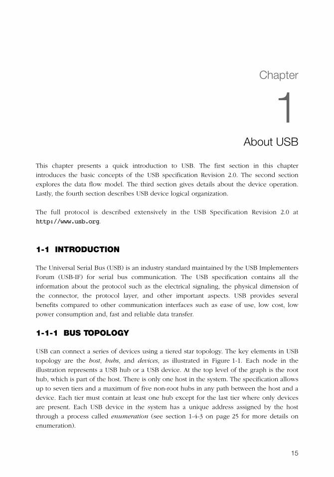
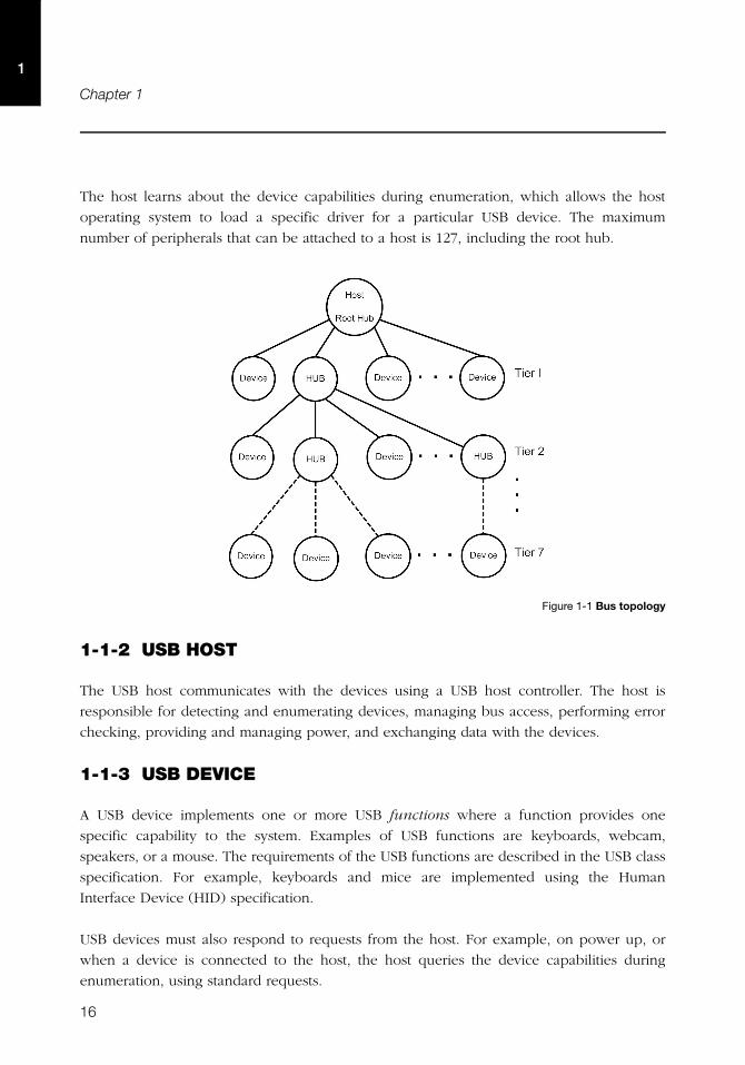
USB can connect a series of devices using a tiered star topology. The key elements in USB
topology are the host, hubs, and devices, as illustrated in Figure 1-1. Each node in the
illustration represents a USB hub or a USB device. At the top level of the graph is the root
hub, which is part of the host. There is only one host in the system. The specification allows
up to seven tiers and a maximum of five non-root hubs in any path between the host and a
device. Each tier must contain at least one hub except for the last tier where only devices
are present. Each USB device in the system has a unique address assigned by the host
through a process called enumeration (see section 1-4-3 on page 25 for more details on
enumeration).
16
Chapter 1
1
The host learns about the device capabilities during enumeration, which allows the host
operating system to load a specific driver for a particular USB device. The maximum
number of peripherals that can be attached to a host is 127, including the root hub.
Figure 1-1 Bus topology
1-1-2 USB HOST
The USB host communicates with the devices using a USB host controller. The host is
responsible for detecting and enumerating devices, managing bus access, performing error
checking, providing and managing power, and exchanging data with the devices.
1-1-3 USB DEVICE
A USB device implements one or more USB functions where a function provides one
specific capability to the system. Examples of USB functions are keyboards, webcam,
speakers, or a mouse. The requirements of the USB functions are described in the USB class
specification. For example, keyboards and mice are implemented using the Human
Interface Device (HID) specification.
USB devices must also respond to requests from the host. For example, on power up, or
when a device is connected to the host, the host queries the device capabilities during
enumeration, using standard requests.
17
Data Flow Model
1
1-2 DATA FLOW MODEL
This section defines the elements involved in the transmission of data across USB.
1-2-1 ENDPOINT
Endpoints function as the point of origin or the point of reception for data. An endpoint is a
logical entity identified using an endpoint address. The endpoint address of a device is
fixed, and is assigned when the device is designed, as opposed to the device address,
which is assigned by the host dynamically during enumeration. An endpoint address
consists of an endpoint number field (0 to 15), and a direction bit that indicates if the
endpoint sends data to the host (IN) or receives data from the host (OUT). The maximum
number of endpoints allowed on a single device is 32.
Endpoints contain configurable characteristics that define the behavior of a USB device:
■ Bus access requirements
■ Bandwidth requirement
■ Error handling
■ Maximum packet size that the endpoint is able to send or receive
■ Transfer type
■ Direction in which data is sent and receive from the host
ENDPOINT ZERO REQUIREMENT
Endpoint zero (also known as Default Endpoint) is a bi-directional endpoint used by the
USB host system to get information, and configure the device via standard requests. All
devices must implement an endpoint zero configured for control transfers (see section
“Control Transfers” on page 18 for more information).
18
Chapter 1
1
1-2-2 PIPES
A USB pipe is a logical association between an endpoint and a software structure in the USB
host software system. USB pipes are used to send data from the host software to the
device’s endpoints. A USB pipe is associated to a unique endpoint address, type of transfer,
maximum packet size, and interval for transfers.
The USB specification defines two types of pipes based on the communication mode:
■ Stream Pipes: Data carried over the pipe is unstructured.
■ Message Pipes: Data carried over the pipe has a defined structure.
The USB specification requires a default control pipe for each device. A default control pipe
uses endpoint zero. The default control pipe is a bi-directional message pipe.
1-2-3 TRANSFER TYPES
The USB specification defines four transfer types that match the bandwidth and services
requirements of the host and the device application using a specific pipe. Each USB transfer
encompasses one or more transactions that sends data to and from the endpoint. The
notion of transactions is related to the maximum payload size defined by each endpoint
type in that when a transfer is greater than this maximum, it will be split into one or more
transactions to fulfill the action.
CONTROL TRANSFERS
Control transfers are used to configure and retrieve information about the device
capabilities. They are used by the host to send standard requests during and after
enumeration. Standard requests allow the host to learn about the device capabilities; for
example, how many and which functions the device contains. Control transfers are also
used for class-specific and vendor-specific requests.
A control transfer contains three stages: Setup, Data, and Status. These stages are detailed in
Table 1-1.
19
Data Flow Model
1
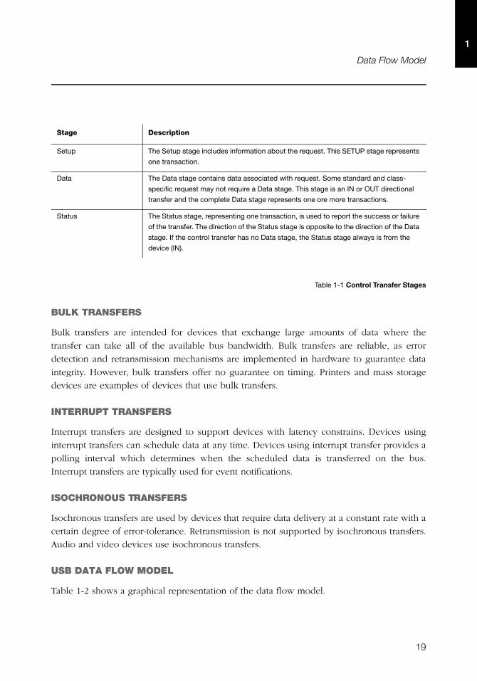
Table 1-1 Control Transfer Stages
BULK TRANSFERS
Bulk transfers are intended for devices that exchange large amounts of data where the
transfer can take all of the available bus bandwidth. Bulk transfers are reliable, as error
detection and retransmission mechanisms are implemented in hardware to guarantee data
integrity. However, bulk transfers offer no guarantee on timing. Printers and mass storage
devices are examples of devices that use bulk transfers.
INTERRUPT TRANSFERS
Interrupt transfers are designed to support devices with latency constrains. Devices using
interrupt transfers can schedule data at any time. Devices using interrupt transfer provides a
polling interval which determines when the scheduled data is transferred on the bus.
Interrupt transfers are typically used for event notifications.
ISOCHRONOUS TRANSFERS
Isochronous transfers are used by devices that require data delivery at a constant rate with a
certain degree of error-tolerance. Retransmission is not supported by isochronous transfers.
Audio and video devices use isochronous transfers.
USB DATA FLOW MODEL
Table 1-2 shows a graphical representation of the data flow model.
Stage Description
Setup The Setup stage includes information about the request. This SETUP stage represents
one transaction.
Data The Data stage contains data associated with request. Some standard and class-
specific request may not require a Data stage. This stage is an IN or OUT directional
transfer and the complete Data stage represents one ore more transactions.
Status The Status stage, representing one transaction, is used to report the success or failure
of the transfer. The direction of the Status stage is opposite to the direction of the Data
stage. If the control transfer has no Data stage, the Status stage always is from the
device (IN).
20
Chapter 1
1
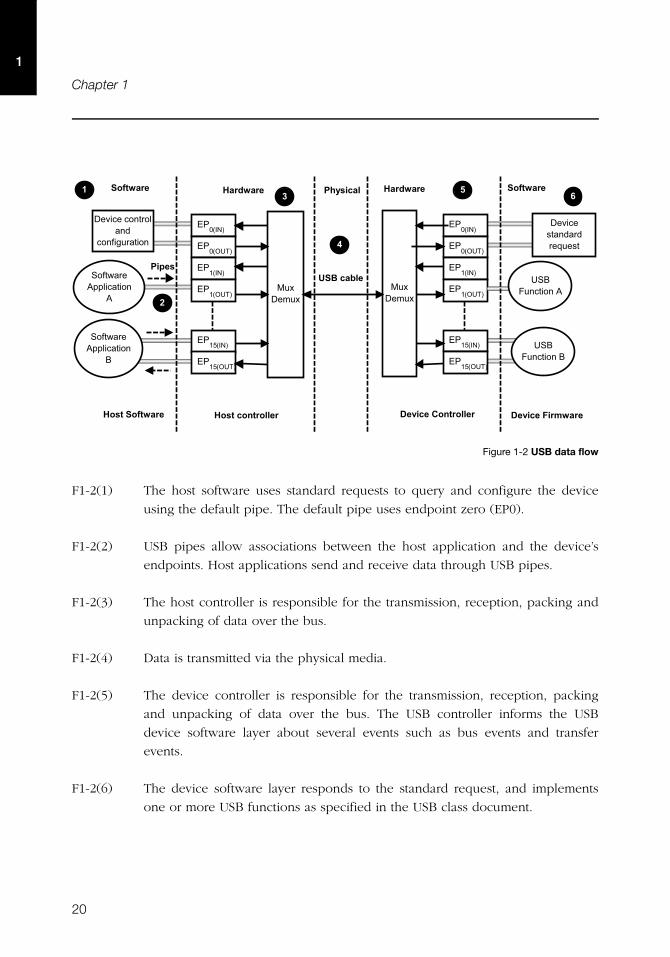
Figure 1-2 USB data flow
F1-2(1) The host software uses standard requests to query and configure the device
using the default pipe. The default pipe uses endpoint zero (EP0).
F1-2(2) USB pipes allow associations between the host application and the device’s
endpoints. Host applications send and receive data through USB pipes.
F1-2(3) The host controller is responsible for the transmission, reception, packing and
unpacking of data over the bus.
F1-2(4) Data is transmitted via the physical media.
F1-2(5) The device controller is responsible for the transmission, reception, packing
and unpacking of data over the bus. The USB controller informs the USB
device software layer about several events such as bus events and transfer
events.
F1-2(6) The device software layer responds to the standard request, and implements
one or more USB functions as specified in the USB class document.
�������
�� ��
��������
�������
��������
��������
���������
�������
��������
�������
��������
��������
���������
�� ��
������� ����������
!
������� ����������
�
�����������
�� ��� �������
��!" ���� #�
��!" ���� #!
� $�� #�� ����� %
�� ��&�����
������������
������� �������
��������
������������� �������������
�����
�
� $�� '�� %��%� ( '�
�
!
"#
�� ���
21
Physical Interface and Power Management
1
TRANSFER COMPLETION
The notion of transfer completion is only relevant for control, bulk and interrupt transfers as
isochronous transfers occur continuously and periodically by nature. In general, control,
bulk and interrupt endpoints must transmit data payload sizes that are less than or equal to
the endpoint’s maximum data payload size. When a transfer’s data payload is greater than
the maximum data payload size, the transfer is split into several transactions whose payload
is maximum-sized except the last transaction which contains the remaining data. A transfer
is deemed complete when:
■ The endpoint transfers exactly the amount of data expected.
■ The endpoint transfers a short packet, that is a packet with a payload size less than the
maximum.
■ The endpoint transfers a zero-length packet.
1-3 PHYSICAL INTERFACE AND POWER MANAGEMENT
USB transfers data and provides power using four-wire cables. The four wires are: Vbus, D+,
D- and Ground. Signaling occurs on the D+ and D- wires.
1-3-1 SPEED
The USB 2.0 specification defines three different speeds.
■ Low Speed: 1.5 Mb/s
■ Full Speed: 12 Mb/s
■ High Speed: 480 Mb/s
22
Chapter 1
1
1-3-2 POWER DISTRIBUTION
The host can supply power to USB devices that are directly connected to the host. USB
devices may also have their own power supplies. USB devices that use power from the
cable are called bus-powered devices. Bus-powered device can draw a maximum of 500
mA from the host. USB devices that have alternative source of power are called self-
powered devices.
1-4 DEVICE STRUCTURE AND ENUMERATION
Before the host application can communicate with a device, the host needs to understand
the capabilities of the device. This process takes place during device enumeration. After
enumeration, the host can assign and load a specific driver to allow communication
between the application and the device.
During enumeration, the host assigns an address to the device, reads descriptors from the
device, and selects a configuration that specifies power and interface requirements. In order
for the host learns about the device’s capabilities, the device must provide information
about itself in the form of descriptors.
This section describes the device logical organization from the USB host’s point of view.
1-4-1 USB DEVICE STRUCTURE
From the host point of view, USB devices are internally organized as a collection of
configurations, interfaces and endpoints.
CONFIGURATION
A USB configuration specifies the capabilities of a device. A configuration consists of a
collection of USB interfaces that implement one or more USB functions. Typically only one
configuration is required for a given device. However, the USB specification allows up to
255 different configurations. During enumeration, the host selects a configuration. Only one
configuration can be active at a time. The device uses a configuration descriptor to inform
the host about a specific configuration’s capabilities.
23
Device Structure and Enumeration
1
INTERFACE
A USB interface or a group of interfaces provides information about a function or class
implemented by the device. An interface can contain multiple mutually exclusive settings
called alternate settings. The device uses an interface descriptor to inform the host about a
specific interface’s capabilities. Each interface descriptor contains a class, subclass, and
protocol codes defined by the USB-IF, and the number of endpoints required for a
particular class implementation.
ALTERNATE SETTINGS
Alternate settings are used by the device to specify mutually exclusive settings for each
interface. The default alternate settings contain the default settings of the device. The device
also uses an interface descriptor to inform the host about an interface’s alternate settings.
ENDPOINT
An interface requires a set of endpoints to communicate with the host. Each interface has
different requirements in terms of the number of endpoints, transfer type, direction,
maximum packet size, and maximum polling interval. The device sends an endpoint
descriptor to notify the host about endpoint capabilities.
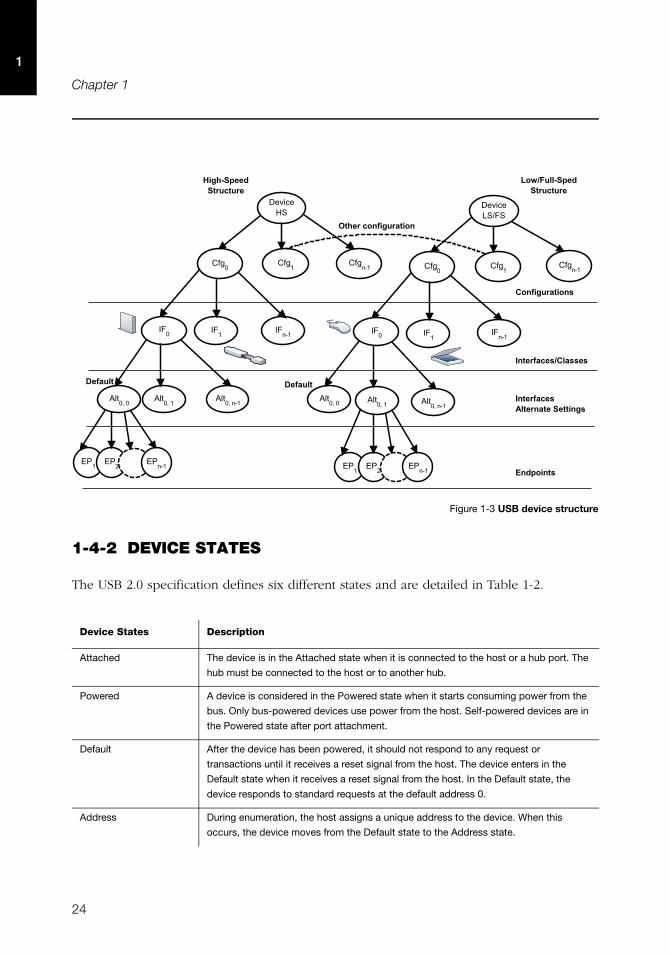
Figure 1-3 shows the hierarchical organization of a USB device. Configurations are grouped
based on the device’s speed. A high-speed device might have a particular configuration in
both high-speed and low/full speed.
24
Chapter 1
1
Figure 1-3 USB device structure
1-4-2 DEVICE STATES
The USB 2.0 specification defines six different states and are detailed in Table 1-2.
Device States Description
Attached The device is in the Attached state when it is connected to the host or a hub port. The
hub must be connected to the host or to another hub.
Powered A device is considered in the Powered state when it starts consuming power from the
bus. Only bus-powered devices use power from the host. Self-powered devices are in
the Powered state after port attachment.
Default After the device has been powered, it should not respond to any request or
transactions until it receives a reset signal from the host. The device enters in the
Default state when it receives a reset signal from the host. In the Default state, the
device responds to standard requests at the default address 0.
Address During enumeration, the host assigns a unique address to the device. When this
occurs, the device moves from the Default state to the Address state.
����$�����$�
� $�� )�
����*#�
��%�&���� ��$��$�
+�&�
+�&�
�"� �"
,�
����*#�
����* ,�
�"�
+�& ,�
'��(�$&��� ��$��$�
� $�� -�."�
����*#�
+�&�
+�&�
�"� �"
,�
����*#� ���
�* ,�
�"�
+�& ,�
���
��/
�� ,�
)���������%$�����
�����%$������
*��������(������
���
��/
�� ,� +� ������
*��������,�������������%�
25
Device Structure and Enumeration
1
Table 1-2 USB Device States
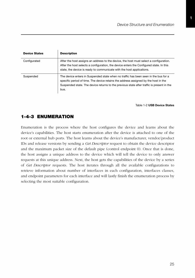
1-4-3 ENUMERATION
Enumeration is the process where the host configures the device and learns about the
device’s capabilities. The host starts enumeration after the device is attached to one of the
root or external hub ports. The host learns about the device’s manufacturer, vendor/product
IDs and release versions by sending a Get Descriptor request to obtain the device descriptor
and the maximum packet size of the default pipe (control endpoint 0). Once that is done,
the host assigns a unique address to the device which will tell the device to only answer
requests at this unique address. Next, the host gets the capabilities of the device by a series
of Get Descriptor requests. The host iterates through all the available configurations to
retrieve information about number of interfaces in each configuration, interfaces classes,
and endpoint parameters for each interface and will lastly finish the enumeration process by
selecting the most suitable configuration.
Configurated After the host assigns an address to the device, the host must select a configuration.
After the host selects a configuration, the device enters the Configured state. In this
state, the device is ready to communicate with the host applications.
Suspended The device enters in Suspended state when no traffic has been seen in the bus for a
specific period of time. The device retains the address assigned by the host in the
Suspended state. The device returns to the previous state after traffic is present in the
bus.
Device States Description

26
Chapter 1
1
27
Chapter
2Getting Started
This chapter gives you some insight into how to install and use the μC/USB-Device stack.
The following topics are explained in this chapter:
■ Prerequisites
■ Downloading the source code files
■ Installing the files
■ Building the sample application
■ Running the sample application
After the completion of this chapter, you should be able to build and run your first USB
application using the μC/USB-Device stack.
28
Chapter 22
2-1 PREREQUISITES
Before running your first application, you must ensure that you have the minimal set of
required tools and components:
■ Toolchain for your specific microcontroller.
■ Development board.
■ μC/USB-Device stack with the source code of at least one of the Micriμm USB classes.
■ USB device controller driver compatible with your hardware for the μC/USB-Device
stack.
■ Board support package (BSP) for your development board.
■ Example project for your selected RTOS (that is μC/OS-II or μC/OS-III).
If Micriμm does not support your USB device controller or BSP, you will have to write your
own device driver. Refer to Chapter 6, “Device Driver Guide” on page 77 for more
information on writing your own USB device driver.
2-2 DOWNLOADING THE SOURCE CODE FILES
μC/USB-Device can be downloaded from the Micriμm customer portal. The distribution
package includes the full source code and documentation. You can log into the Micriμm
customer portal at the address below to begin your download (you must have a valid
license to gain access to the file):
http://micrium.com/login
μC/USB-Device depends on other modules, and you need to install all the required
modules before building your application. Depending on the availability of support for your
hardware platform, ports and drivers may or may not be available for download from the
customer portal. Table 2-1 shows the module dependency for μC/USB-Device.
29
Downloading the Source Code Files 2
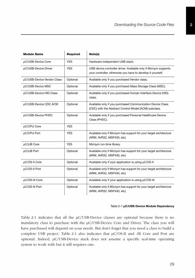
Table 2-1 μC/USB-Device Module Dependency
Table 2-1 indicates that all the μC/USB-Device classes are optional because there is no
mandatory class to purchase with the μC/USB-Device Core and Driver. The class you will
have purchased will depend on your needs. But don’t forget that you need a class to build a
complete USB project. Table 2-1 also indicates that μC/OS-II and -III Core and Port are
optional. Indeed, μC/USB-Device stack does not assume a specific real-time operating
system to work with but it still requires one.
Module Name Required Note(s)
μC/USB-Device Core YES Hardware independent USB stack.
μC/USB-Device Driver YES USB device controller driver. Available only if Micriμm supports
your controller, otherwise you have to develop it yourself.
μC/USB-Device Vendor Class Optional Available only if you purchased Vendor class.
μC/USB-Device MSC Optional Available only if you purchased Mass Storage Class (MSC).
μC/USB-Device HID Class Optional Available only if you purchased Human Interface Device (HID)
class.
μC/USB-Device CDC ACM Optional Available only if you purchased Communication Device Class
(CDC) with the Abstract Control Model (ACM) subclass.
μC/USB-Device PHDC Optional Available only if you purchased Personal Healthcare Device
Class (PHDC).
μC/CPU Core YES
μC/CPU Port YES Available only if Micriμm has support for your target architecture
(ARM, AVR32, MSP430, etc)
μC/LIB Core YES Micriμm run-time library.
μC/LIB Port Optional Available only if Micriμm has support for your target architecture
(ARM, AVR32, MSP430, etc)
μC/OS-II Core Optional Available only if your application is using μC/OS-II
μC/OS-II Port Optional Available only if Micriμm has support for your target architecture
(ARM, AVR32, MSP430, etc)
μC/OS-III Core Optional Available only if your application is using μC/OS-III
μC/OS-III Port Optional Available only if Micriμm has support for your target architecture
(ARM, AVR32, MSP430, etc)
30
Chapter 22
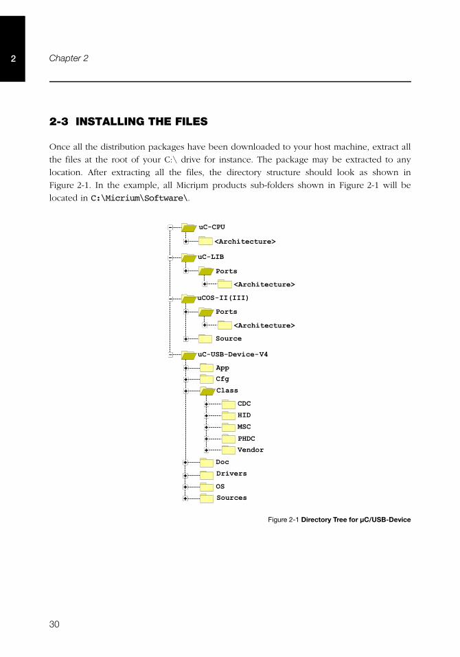
2-3 INSTALLING THE FILES
Once all the distribution packages have been downloaded to your host machine, extract all
the files at the root of your C:\ drive for instance. The package may be extracted to any
location. After extracting all the files, the directory structure should look as shown in
Figure 2-1. In the example, all Micriμm products sub-folders shown in Figure 2-1 will be
located in C:\Micrium\Software\.
Figure 2-1 Directory Tree for μC/USB-Device
���������� � ���
������
���� � ����� �
�������������� �
�������������������
������� !��
���"��#���"����$%�
�������
�����
��
���� � ���
31
Building the Sample Application 2
2-4 BUILDING THE SAMPLE APPLICATION
This section describes all the steps required to build a USB-based application. The
instructions provided in this section are not intended for any particular toolchain, but
instead are described in a generic way that can be adapted to any toolchain.
The best way to start building a USB-based project is to start from an existing project. If you
are using μC/OS-II or μC/OS-III, Micriμm provides example projects for multiple
development boards and compilers. If your target board is not listed on Micriμm’s web site,
you can download an example project for a similar board or microcontroller.
The purpose of the sample project is to allow a host to enumerate your device. You will add
a USB class instance to both, full-speed and high-speed configurations (if both are
supported by your controller). Refer to section 7-1 “Class Instance Concept” on page 99 for
more details about the class instance concept. After you have successfully completed and
run the sample project, you can use it as a starting point to run other USB class demos you
may have purchased.
μC/USB-Device requires a Real-Time Operating System (RTOS). The following assumes that
you have a working example project running on μC/OS-II or μC/OS-III.
2-4-1 UNDERSTANDING MICRIUM EXAMPLES
A Micriμm example project is usually placed in the following directory structure.
\Micrium
\Software
\EvalBoards
\<manufacturer>
\<board_name>
\<compiler>
\<project name>
\*.*
Note that Micriμm does not provide by default an example project with the μC/USB-Device
distribution package. Micriμm examples are provided to customers in specific situations. If it
happens that you receive a Micriμm example, the directory structure shown above is
generally used by Micriμm. You may use a different directory structure to store the
application and toolchain projects files.
32
Chapter 22
\Micrium
This is where Micriμm places all software components and projects. This directory is
generally located at the root directory.
\Software
This sub-directory contains all software components and projects.
\EvalBoards
This sub-directory contains all projects related to evaluation boards supported by Micriμm.
\<manufacturer>
This is the name of the manufacturer of the evaluation board. In some cases this can be also
the name of the microcontroller manufacturer.
\<board name>
This is the name of the evaluation board.
\<compiler>
This is the name of the compiler or compiler manufacturer used to build the code for the
evaluation board.
\<project name>
The name of the project that will be demonstrated. For example a simple μC/USB-Device
with μC/OS-III project might have the project name ‘uCOS-III-USBD’.
\*.*
These are the source files for the project. This directory contains configuration files
app_cfg.h, os_cfg.h, os_cfg_app.h, cpu_cfg.h and other project-required sources files.
os_cfg.h is a configuration file used to configure μC/OS-III (or μC/OS-II) parameters
such as the maximum number of tasks, events, objects, which μC/OS-III services are
enabled (semaphores, mailboxes, queues), and so on. os_cfg.h is a required file for
any μC/OS-III application. See the μC/OS-III documentation and books for further
information.
app.c contains the application code for the example project. As with most C programs,
code execution starts at main(). At a minimum, app.c initializes μC/OS-III and creates
a startup task that initializes other Micriμm modules.
33
Building the Sample Application 2
app_cfg.h is a configuration file for your application. This file contains #defines to
configure the priorities and stack sizes of your application and the Micriμm modules’
tasks.
app_<module>.c and app_<module>.h These optional files contain the Micriμm
modules’ (μC/TCP-IP, μC/FS, μC/USB-Host, etc) initialization code. They may or may
not be present in the example projects.
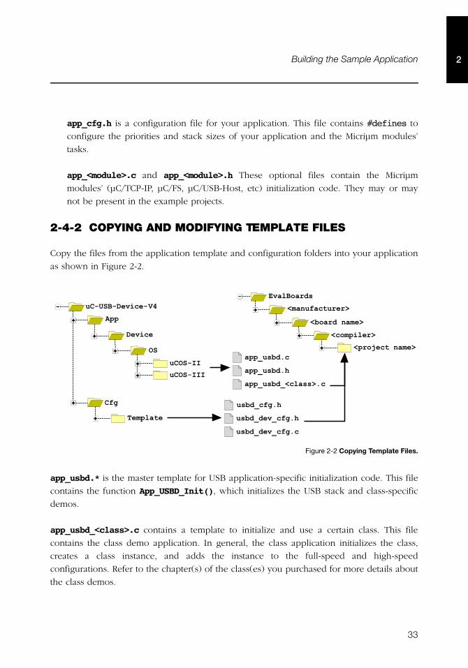
2-4-2 COPYING AND MODIFYING TEMPLATE FILES
Copy the files from the application template and configuration folders into your application
as shown in Figure 2-2.
Figure 2-2 Copying Template Files.
app_usbd.* is the master template for USB application-specific initialization code. This file
contains the function App_USBD_Init(), which initializes the USB stack and class-specific
demos.
app_usbd_<class>.c contains a template to initialize and use a certain class. This file
contains the class demo application. In general, the class application initializes the class,
creates a class instance, and adds the instance to the full-speed and high-speed
configurations. Refer to the chapter(s) of the class(es) you purchased for more details about
the class demos.
������������������
���
���������
&�'� ! �
��������
(�! ��!%��'!$��! ���
�)�!%*$!'����'�� ��
���+� *$!'��
*!��,��)%,� !���-*!��,��)%-�*!��,��)%-
��)%,%��,��-��)%,%��,��-���)%,��-�
�����
34
Chapter 22
usbd_cfg.h is a configuration file used to setup μC/USB-Device stack parameters such as
the maximum number of configurations, interfaces, or class-related parameters.
usbd_dev_cfg.c and usbd_dev_cfg.h are configuration files used to set device parameters
such as vendor ID, product ID, and device release number. They also serve to configure the
USB device controller driver parameters, such as base address, dedicated memory base
address and size, controller’s speed, and endpoint capabilities.
MODIFY DEVICE CONFIGURATION
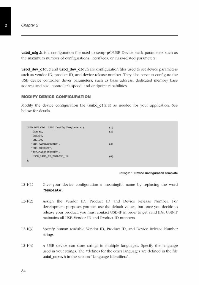
Modify the device configuration file (usbd_cfg.c) as needed for your application. See
below for details.
Listing 2-1 Device Configuration Template
L2-1(1) Give your device configuration a meaningful name by replacing the word
“Template”.
L2-1(2) Assign the Vendor ID, Product ID and Device Release Number. For
development purposes you can use the default values, but once you decide to
release your product, you must contact USB-IF in order to get valid IDs. USB-IF
maintains all USB Vendor ID and Product ID numbers.
L2-1(3) Specify human readable Vendor ID, Product ID, and Device Release Number
strings.
L2-1(4) A USB device can store strings in multiple languages. Specify the language
used in your strings. The #defines for the other languages are defined in the file
usbd_core.h in the section “Language Identifiers”.
USBD_DEV_CFG USBD_DevCfg_Template = { (1)
0xFFFE, (2)
0x1234,
0x0100,
"OEM MANUFACTURER", (3)
"OEM PRODUCT",
"1234567890ABCDEF",
USBD_LANG_ID_ENGLISH_US (4)
};
35
Building the Sample Application 2
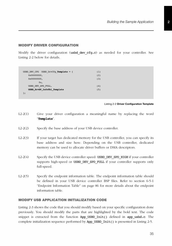
MODIFY DRIVER CONFIGURATION
Modify the driver configuration (usbd_dev_cfg.c) as needed for your controller. See
Listing 2-2 below for details.
Listing 2-2 Driver Configuration Template
L2-2(1) Give your driver configuration a meaningful name by replacing the word
“Template”.
L2-2(2) Specify the base address of your USB device controller.
L2-2(3) If your target has dedicated memory for the USB controller, you can specify its
base address and size here. Depending on the USB controller, dedicated
memory can be used to allocate driver buffers or DMA descriptors.
L2-2(4) Specify the USB device controller speed: USBD_DEV_SPD_HIGH if your controller
supports high-speed or USBD_DEV_SPD_FULL if your controller supports only
full-speed.
L2-2(5) Specify the endpoint information table. The endpoint information table should
be defined in your USB device controller BSP files. Refer to section 6-5-1
“Endpoint Information Table” on page 86 for more details about the endpoint
information table.
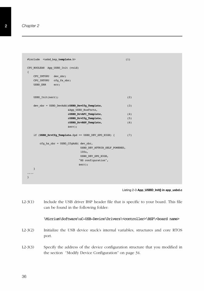
MODIFY USB APPLICATION INITIALIZATION CODE
Listing 2-3 shows the code that you should modify based on your specific configuration done
previously. You should modify the parts that are highlighted by the bold text. The code
snippet is extracted from the function App_USBD_Init() defined in app_usbd.c. The
complete initialization sequence performed by App_USBD_Init() is presented in Listing 2-5.
USBD_DRV_CFG USBD_DrvCfg_Template = { (1)
0x00000000, (2)
0x00000000, (3)
0u,
USBD_DEV_SPD_FULL, (4)
USBD_DrvEP_InfoTbl_Template (5)
};
36
Chapter 22
Listing 2-3 App_USBD_Init() in app_usbd.c
L2-3(1) Include the USB driver BSP header file that is specific to your board. This file
can be found in the following folder:
\Micrium\Software\uC-USB-Device\Drivers\<controller>\BSP\<board name>
L2-3(2) Initialize the USB device stack’s internal variables, structures and core RTOS
port.
L2-3(3) Specify the address of the device configuration structure that you modified in
the section “Modify Device Configuration” on page 34.
#include <usbd_bsp_template.h> (1)
CPU_BOOLEAN App_USBD_Init (void)
{
CPU_INT08U dev_nbr;
CPU_INT08U cfg_fs_nbr;
USBD_ERR err;
USBD_Init(&err); (2)
dev_nbr = USBD_DevAdd(&USBD_DevCfg_Template, (3)
&App_USBD_BusFncts,
&USBD_DrvAPI_Template, (4)
&USBD_DrvCfg_Template, (5)
&USBD_DrvBSP_Template, (6)
&err);
if (USBD_DrvCfg_Template.Spd == USBD_DEV_SPD_HIGH) { (7)
cfg_hs_nbr = USBD_CfgAdd( dev_nbr,
USBD_DEV_ATTRIB_SELF_POWERED,
100u,
USBD_DEV_SPD_HIGH,
"HS configuration",
&err);
}
....
}
37
Building the Sample Application 2
L2-3(4) Specify the address of the driver API structure. The driver’s API structure is
defined in the driver’s header file named usbd_drv_<controller>.h.
L2-3(5) Specify the address of the driver configuration structure that you modified in
the section “Modify Driver Configuration” on page 35.
L2-3(6) Specify the endpoint information table. The endpoint information table should
be defined in your USB device controller BSP files.
L2-3(7) If the device controller supports high-speed, create a high-speed configuration
for the specified device.
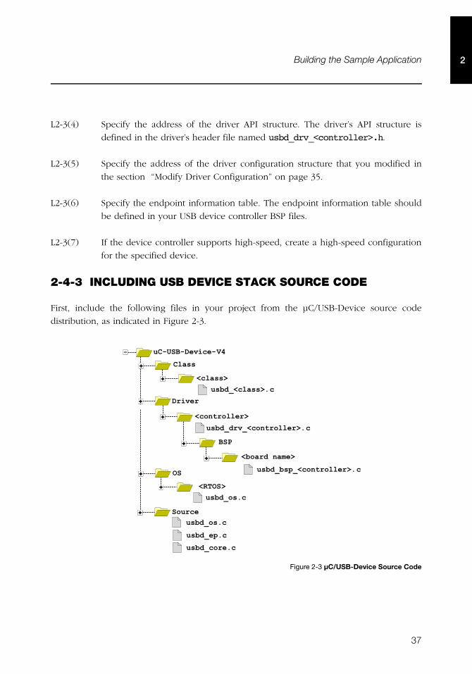
2-4-3 INCLUDING USB DEVICE STACK SOURCE CODE
First, include the following files in your project from the μC/USB-Device source code
distribution, as indicated in Figure 2-3.
Figure 2-3 μC/USB-Device Source Code
���������������� !��
����
� !���
��$ � ��
��)%,� !���-
��)%,%�,��$ � ��-���
��)%,)��,��$ � ��-�)�!%*$!'��
���.&�����)%,��-
������)%,��-��)%,��-��)%,��-
38
Chapter 22
Second, add the following include paths to your project settings:
\Micrium\Software\uC-USB-Device\Source\
\Micrium\Software\uC-USB-Device\Class\<class>\
\Micrium\Software\uC-USB-Device\Drivers\<controller>
\Micrium\Software\uC-USB-Device\Drivers\<controller>\BSP\<board name>
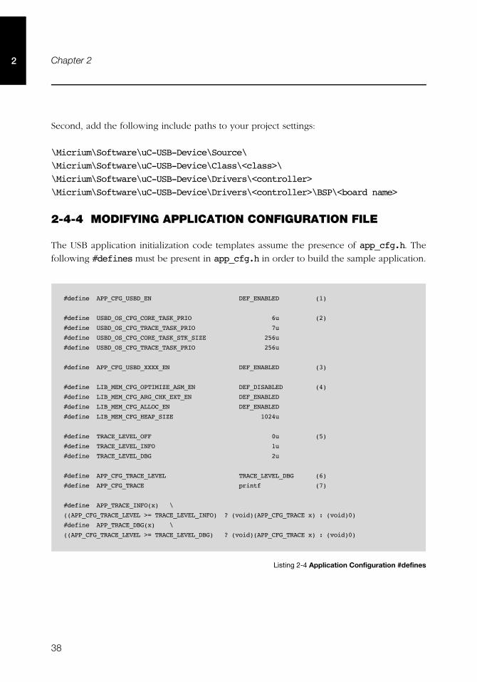
2-4-4 MODIFYING APPLICATION CONFIGURATION FILE
The USB application initialization code templates assume the presence of app_cfg.h. The
following #defines must be present in app_cfg.h in order to build the sample application.
Listing 2-4 Application Configuration #defines
#define APP_CFG_USBD_EN DEF_ENABLED (1)
#define USBD_OS_CFG_CORE_TASK_PRIO 6u (2)
#define USBD_OS_CFG_TRACE_TASK_PRIO 7u
#define USBD_OS_CFG_CORE_TASK_STK_SIZE 256u
#define USBD_OS_CFG_TRACE_TASK_PRIO 256u
#define APP_CFG_USBD_XXXX_EN DEF_ENABLED (3)
#define LIB_MEM_CFG_OPTIMIZE_ASM_EN DEF_DISABLED (4)
#define LIB_MEM_CFG_ARG_CHK_EXT_EN DEF_ENABLED
#define LIB_MEM_CFG_ALLOC_EN DEF_ENABLED
#define LIB_MEM_CFG_HEAP_SIZE 1024u
#define TRACE_LEVEL_OFF 0u (5)
#define TRACE_LEVEL_INFO 1u
#define TRACE_LEVEL_DBG 2u
#define APP_CFG_TRACE_LEVEL TRACE_LEVEL_DBG (6)
#define APP_CFG_TRACE printf (7)
#define APP_TRACE_INFO(x) \
((APP_CFG_TRACE_LEVEL >= TRACE_LEVEL_INFO) ? (void)(APP_CFG_TRACE x) : (void)0)
#define APP_TRACE_DBG(x) \
((APP_CFG_TRACE_LEVEL >= TRACE_LEVEL_DBG) ? (void)(APP_CFG_TRACE x) : (void)0)
39
Building the Sample Application 2
L2-4(1) APP_CFG_USBD_EN enables or disables the USB application initialization code.
L2-4(2) These #defines relate to the μC/USB-Device OS port. The μC/USB-Device core
requires only one task to manage control requests and asynchronous transfers,
and a second, optional task to output trace events (if trace capability is
enabled). To properly set the priority of the core and debug tasks, refer to
section 5-2-1 “Task Priorities” on page 69.
L2-4(3) This #define enables the USB class-specific demo. The token XXXX in the
constant APP_CFG_USBD_XXXX_EN is the name of the class and can be replaced
by CDC, HID, MSC, PHDC or VENDOR.
L2-4(4) Configure the desired size of the heap memory. Heap memory is only used for
μC/USB-Device drivers that use internal buffers and DMA descriptors which are
allocated at run-time. Refer to the μC/LIB documentation for more details on
the other μC/LIB constants.
L2-4(5) Most Micriμm examples contain application trace macros to output human-
readable debugging information. Two levels of tracing are enabled: INFO and
DBG. INFO traces high-level operations, and DBG traces high-level operations
and return errors. Application-level tracing is different from μC/USB-Device
tracing (refer to Chapter 13, “Debug and Trace” on page 231 for more details).
L2-4(6) Define the application trace level.
L2-4(7) Specify which function should be used to redirect the output of human-
readable application tracing. You can select the standard output via printf(),
or another output such as a text terminal using a serial interface.
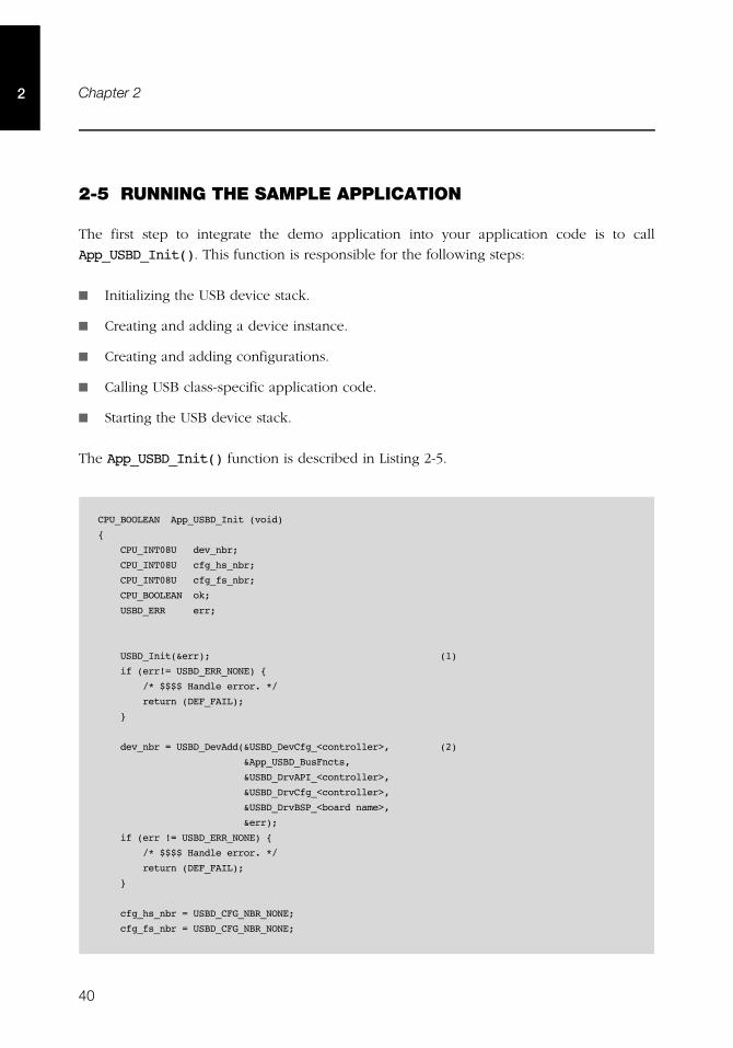
40
Chapter 22
2-5 RUNNING THE SAMPLE APPLICATION
The first step to integrate the demo application into your application code is to call
App_USBD_Init(). This function is responsible for the following steps:
■ Initializing the USB device stack.
■ Creating and adding a device instance.
■ Creating and adding configurations.
■ Calling USB class-specific application code.
■ Starting the USB device stack.
The App_USBD_Init() function is described in Listing 2-5.
CPU_BOOLEAN App_USBD_Init (void)
{
CPU_INT08U dev_nbr;
CPU_INT08U cfg_hs_nbr;
CPU_INT08U cfg_fs_nbr;
CPU_BOOLEAN ok;
USBD_ERR err;
USBD_Init(&err); (1)
if (err!= USBD_ERR_NONE) {
/* $$$$ Handle error. */
return (DEF_FAIL);
}
dev_nbr = USBD_DevAdd(&USBD_DevCfg_<controller>, (2)
&App_USBD_BusFncts,
&USBD_DrvAPI_<controller>,
&USBD_DrvCfg_<controller>,
&USBD_DrvBSP_<board name>,
&err);
if (err != USBD_ERR_NONE) {
/* $$$$ Handle error. */
return (DEF_FAIL);
}
cfg_hs_nbr = USBD_CFG_NBR_NONE;
cfg_fs_nbr = USBD_CFG_NBR_NONE;
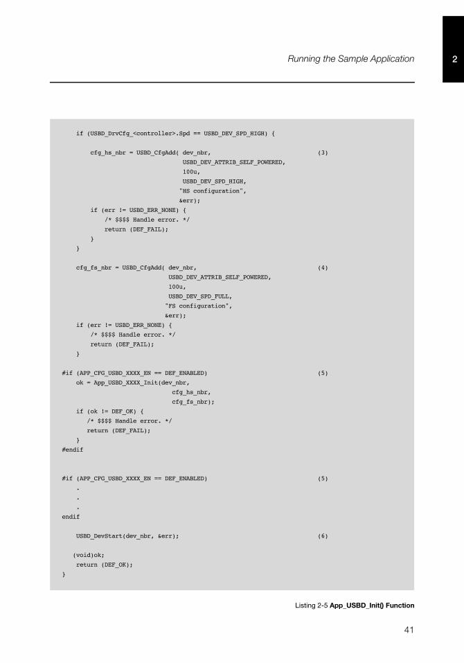
41
Running the Sample Application 2
Listing 2-5 App_USBD_Init() Function
if (USBD_DrvCfg_<controller>.Spd == USBD_DEV_SPD_HIGH) {
cfg_hs_nbr = USBD_CfgAdd( dev_nbr, (3)
USBD_DEV_ATTRIB_SELF_POWERED,
100u,
USBD_DEV_SPD_HIGH,
"HS configuration",
&err);
if (err != USBD_ERR_NONE) {
/* $$$$ Handle error. */
return (DEF_FAIL);
}
}
cfg_fs_nbr = USBD_CfgAdd( dev_nbr, (4)
USBD_DEV_ATTRIB_SELF_POWERED,
100u,
USBD_DEV_SPD_FULL,
"FS configuration",
&err);
if (err != USBD_ERR_NONE) {
/* $$$$ Handle error. */
return (DEF_FAIL);
}
#if (APP_CFG_USBD_XXXX_EN == DEF_ENABLED) (5)
ok = App_USBD_XXXX_Init(dev_nbr,
cfg_hs_nbr,
cfg_fs_nbr);
if (ok != DEF_OK) {
/* $$$$ Handle error. */
return (DEF_FAIL);
}
#endif
#if (APP_CFG_USBD_XXXX_EN == DEF_ENABLED) (5)
.
.
.
endif
USBD_DevStart(dev_nbr, &err); (6)
(void)ok;
return (DEF_OK);
}
42
Chapter 22
L2-5(1) USBD_Init() initializes the USB device stack. This must be the first USB
function called by your application’s initialization code. If μC/USB-Device is
used with μC/OS-II or -III, OSInit() must be called prior to USBD_Init() in
order to intialize the kernel services.
L2-5(2) USBD_DevAdd() creates and adds a USB device instance. A given USB device
instance is associated with a single USB device controller. μC/USB-Device can
support multiple USB device controllers concurrently. If your target supports
multiple controllers, you can create multiple USB device instances for them.
The function USBD_DevAdd() returns a device instance number; this number is
used as a parameter for all subsequent operations.
L2-5(3) Create and add a high-speed configuration to your device. USBD_CfgAdd()
creates and adds a configuration to the USB device stack. At a minimum, your
USB device application only needs one full-speed and one high-speed
configuration if your device is a high-speed capable device. For a full-speed
device, only a full-speed configuration will be required. You can create as
many configurations as needed by your application, and you can associate
multiple instances of USB classes to these configurations. For example, you can
create a configuration to contain a mass storage device, and another
configuration for a human interface device such as a keyboard, and a vendor
specific device.
L2-5(4) Create and add a full-speed configuration to your device.
L2-5(5) Initialize the class-specific application demos by calling the function
App_USBD_XXXX_Init() where XXXX can be CDC, HID, MSC, PHDC or
VENDOR. Class-specific demos are enabled and disabled using the
APP_CFG_USB_XXXX_EN #define.
L2-5(6) After all the class instances are created and added to the device configurations,
the application should call USBD_DevStart(). This function connects the
device with the host by enabling the pull-up resistor on the D+ line.
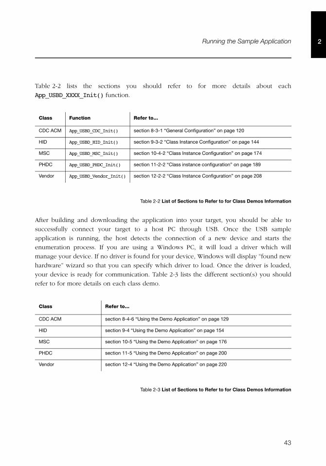
43
Running the Sample Application 2
Table 2-2 lists the sections you should refer to for more details about each
App_USBD_XXXX_Init() function.
Table 2-2 List of Sections to Refer to for Class Demos Information
After building and downloading the application into your target, you should be able to
successfully connect your target to a host PC through USB. Once the USB sample
application is running, the host detects the connection of a new device and starts the
enumeration process. If you are using a Windows PC, it will load a driver which will
manage your device. If no driver is found for your device, Windows will display “found new
hardware” wizard so that you can specify which driver to load. Once the driver is loaded,
your device is ready for communication. Table 2-3 lists the different section(s) you should
refer to for more details on each class demo.
Table 2-3 List of Sections to Refer to for Class Demos Information
Class Function Refer to...
CDC ACM App_USBD_CDC_Init() section 8-3-1 “General Configuration” on page 120
HID App_USBD_HID_Init() section 9-3-2 “Class Instance Configuration” on page 144
MSC App_USBD_MSC_Init() section 10-4-2 “Class Instance Configuration” on page 174
PHDC App_USBD_PHDC_Init() section 11-2-2 “Class instance configuration” on page 189
Vendor App_USBD_Vendor_Init() section 12-2-2 “Class Instance Configuration” on page 208
Class Refer to...
CDC ACM section 8-4-6 “Using the Demo Application” on page 129
HID section 9-4 “Using the Demo Application” on page 154
MSC section 10-5 “Using the Demo Application” on page 176
PHDC section 11-5 “Using the Demo Application” on page 200
Vendor section 12-4 “Using the Demo Application” on page 220

44
Chapter 22
45
Chapter
3Host Operating Systems
The major host operating systems (OS), such as Microsoft Windows, Apple Mac OS and
Linux, recognize a wide range of USB devices belonging to standard classes defined by the
USB Implementers Forum. Upon connection of the USB device, any host operating systems
perform the following general steps:
1 Enumerating the USB device to learn about its characteristics.
2 Loading a proper driver according to its characteristics’ analysis in order to manage the
device.
3 Communicating with the device.
Step 2, where a driver is loaded to handle the device is performed differently by each major
host operating system. Usually, a native driver provided by the operating system manages a
device complying to a standard class (for instance, Audio, HID, MSC, Video, etc.) In this
case, the native driver loading is transparent to you. In general, the OS won’t ask you for
specific actions during the driver loading process. On the other hand, a vendor-specific
device requires a vendor-specific driver provided by the device manufacturer. Vendor-
specific devices don’t fit into any standard class or don’t use the standard protocols for an
existing standard class. In this situation, the OS may explicitly ask your intervention during
the driver loading process.
During step 3, your application may have to find the USB device attached to the OS before
communication with it. Each major OS uses a different method to allow you to find a
specific device.
This chapter gives you the necessary information in case your intervention is required
during the USB device driver loading and in case your application needs to find a device
attached to the computer. For the moment, this chapter describes this process only for the
Windows operating system.
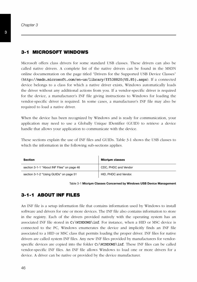
46
Chapter 3
3
3-1 MICROSOFT WINDOWS
Microsoft offers class drivers for some standard USB classes. These drivers can also be
called native drivers. A complete list of the native drivers can be found in the MSDN
online documentation on the page titled “Drivers for the Supported USB Device Classes”
(http://msdn.microsoft.com/en-us/library/ff538820(VS.85).aspx). If a connected
device belongs to a class for which a native driver exists, Windows automatically loads
the driver without any additional actions from you. If a vendor-specific driver is required
for the device, a manufacturer’s INF file giving instructions to Windows for loading the
vendor-specific driver is required. In some cases, a manufacturer’s INF file may also be
required to load a native driver.
When the device has been recognized by Windows and is ready for communication, your
application may need to use a Globally Unique IDentifier (GUID) to retrieve a device
handle that allows your application to communicate with the device.
These sections explain the use of INF files and GUIDs. Table 3-1 shows the USB classes to
which the information in the following sub-sections applies.
Table 3-1 Micriμm Classes Concerned by Windows USB Device Management
3-1-1 ABOUT INF FILES
An INF file is a setup information file that contains information used by Windows to install
software and drivers for one or more devices. The INF file also contains information to store
in the registry. Each of the drivers provided natively with the operating system has an
associated INF file stored in C:\WINDOWS\inf. For instance, when a HID or MSC device is
connected to the PC, Windows enumerates the device and implicitly finds an INF file
associated to a HID or MSC class that permits loading the proper driver. INF files for native
drivers are called system INF files. Any new INF files provided by manufacturers for vendor-
specific devices are copied into the folder C:\WINDOWS\inf. These INF files can be called
vendor-specific INF files. An INF file allows Windows to load one or more drivers for a
device. A driver can be native or provided by the device manufacturer.
Section Micriμm classes
section 3-1-1 “About INF Files” on page 46 CDC, PHDC and Vendor
section 3-1-2 “Using GUIDs” on page 51 HID, PHDC and Vendor.
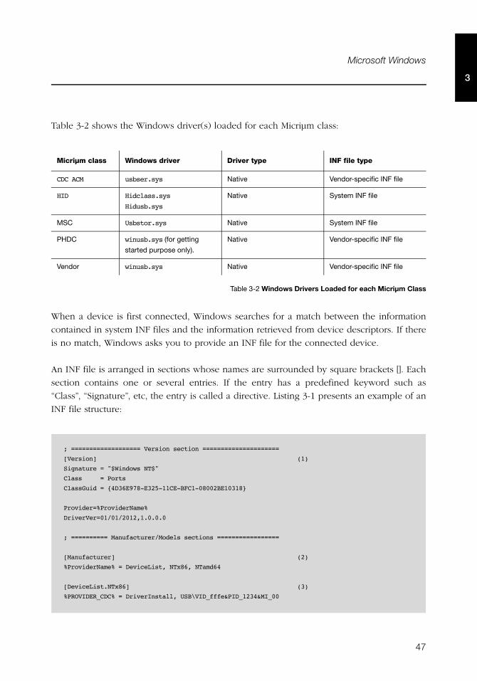
47
Microsoft Windows
3
Table 3-2 shows the Windows driver(s) loaded for each Micriμm class:
Table 3-2 Windows Drivers Loaded for each Micriμm Class
When a device is first connected, Windows searches for a match between the information
contained in system INF files and the information retrieved from device descriptors. If there
is no match, Windows asks you to provide an INF file for the connected device.
An INF file is arranged in sections whose names are surrounded by square brackets []. Each
section contains one or several entries. If the entry has a predefined keyword such as
“Class”, “Signature”, etc, the entry is called a directive. Listing 3-1 presents an example of an
INF file structure:
Micriμm class Windows driver Driver type INF file type
CDC ACM usbser.sys Native Vendor-specific INF file
HID Hidclass.sys
Hidusb.sys
Native System INF file
MSC Usbstor.sys Native System INF file
PHDC winusb.sys (for getting
started purpose only).
Native Vendor-specific INF file
Vendor winusb.sys Native Vendor-specific INF file
; =================== Version section =====================
[Version] (1)
Signature = "$Windows NT$"
Class = Ports
ClassGuid = {4D36E978-E325-11CE-BFC1-08002BE10318}
Provider=%ProviderName%
DriverVer=01/01/2012,1.0.0.0
; ========== Manufacturer/Models sections =================
[Manufacturer] (2)
%ProviderName% = DeviceList, NTx86, NTamd64
[DeviceList.NTx86] (3)
%PROVIDER_CDC% = DriverInstall, USB\VID_fffe&PID_1234&MI_00
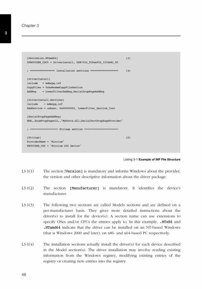
48
Chapter 3
3
Listing 3-1 Example of INF File Structure
L3-1(1) The section [Version] is mandatory and informs Windows about the provider,
the version and other descriptive information about the driver package.
L3-1(2) The section [Manufacturer] is mandatory. It identifies the device’s
manufacturer.
L3-1(3) The following two sections are called Models sections and are defined on a
per-manufacturer basis. They gives more detailed instructions about the
driver(s) to install for the device(s). A section name can use extensions to
specify OSes and/or CPUs the entries apply to. In this example, .NTx86 and
.NTamd64 indicate that the driver can be installed on an NT-based Windows
(that is Windows 2000 and later), on x86- and x64-based PC respectively.
L3-1(4) The installation sections actually install the driver(s) for each device described
in the Model section(s). The driver installation may involve reading existing
information from the Windows registry, modifying existing entries of the
registry or creating new entries into the registry.
[DeviceList.NTamd64] (3)
%PROVIDER_CDC% = DriverInstall, USB\VID_fffe&PID_1234&MI_00
; ================ Installation sections ================== (4)
[DriverInstall]
include = mdmcpq.inf
CopyFiles = FakeModemCopyFileSection
AddReg = LowerFilterAddReg,SerialPropPageAddReg
[DriverInstall.Services]
include = mdmcpq.inf
AddService = usbser, 0x00000002, LowerFilter_Service_Inst
[SerialPropPageAddReg]
HKR,,EnumPropPages32,,"MsPorts.dll,SerialPortPropPageProvider"
; ================== Strings section ======================
[Strings] (5)
ProviderName = "Micrium"
PROVIDER_CDC = "Micrium CDC Device"
49
Microsoft Windows
3
L3-1(5) The section [Strings] is mandatory and it is used to define each string key
token indicated by %string name% in the INF file.
Refer to the MSDN online documentation on this web page for more details about INF
sections and directives: http://msdn.microsoft.com/en-us/library/ff549520.aspx.
You will be able to modify some sections in order to match the INF file to your device
characteristics, such as Vendor ID, Product ID and human-readable strings describing the
device. The sections are:
■ Models section
■ [Strings] section
To identify possible drivers for a device, Windows looks in the Models section for a device
identification string that matches a string created from information in the device’s
descriptors. Every USB device has a device ID, that is a hardware ID created by the
Windows USB host stack from information contained in the Device descriptor. A device ID
has the following form:
USB\Vid_xxxx&Pid_yyyy
xxxx, yyyy, represent the value of the Device descriptor fields “idVendor” and “idProduct”
respectively (refer to the Universal Serial Bus Specification, revision 2.0, section 9.6.1 for
more details about the Device descriptor fields). This string allows Windows to load a driver
for the device. You can modify xxxx and yyyy to match your device’s Vendor and Product
IDs. In Listing 2-1, the hardware ID defines the Vendor ID 0xFFFE and the Product ID
0x1234.
Composite devices, formed of several functions, can specify a driver for each function. In
this case, the device has a device ID for each interface that represents a function. A device
ID for an interface has the following form:
USB\Vid_xxxx&Pid_yyyy&MI_ww
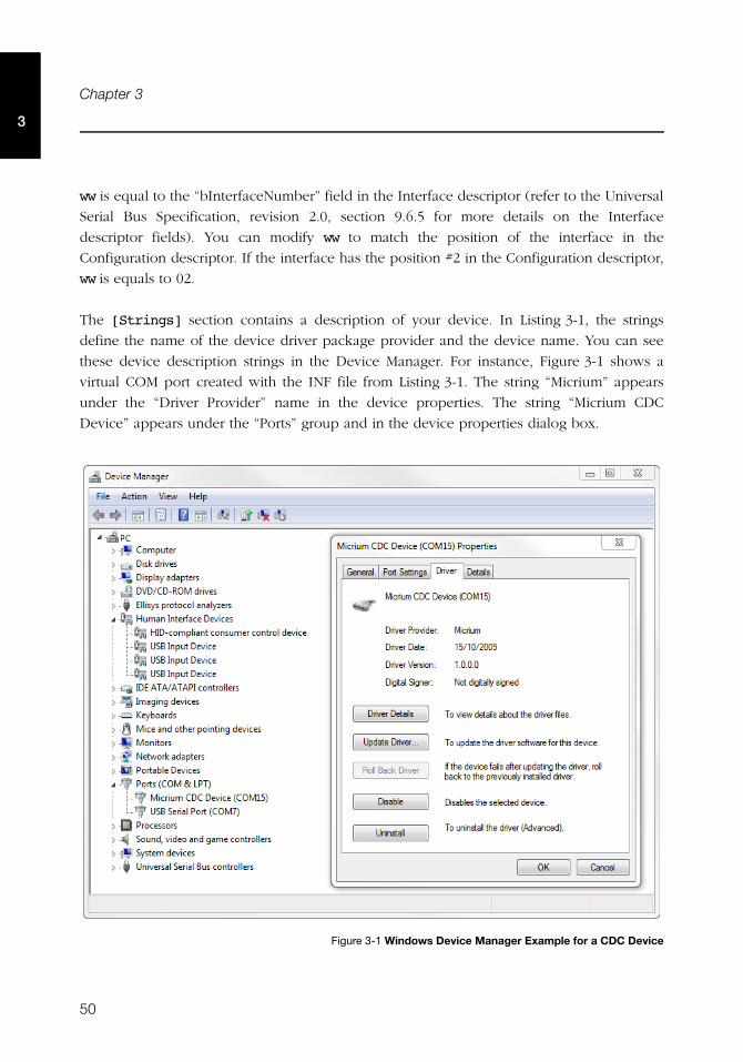
50
Chapter 3
3
ww is equal to the “bInterfaceNumber” field in the Interface descriptor (refer to the Universal
Serial Bus Specification, revision 2.0, section 9.6.5 for more details on the Interface
descriptor fields). You can modify ww to match the position of the interface in the
Configuration descriptor. If the interface has the position #2 in the Configuration descriptor,
ww is equals to 02.
The [Strings] section contains a description of your device. In Listing 3-1, the strings
define the name of the device driver package provider and the device name. You can see
these device description strings in the Device Manager. For instance, Figure 3-1 shows a
virtual COM port created with the INF file from Listing 3-1. The string “Micrium” appears
under the “Driver Provider” name in the device properties. The string “Micrium CDC
Device” appears under the “Ports” group and in the device properties dialog box.
Figure 3-1 Windows Device Manager Example for a CDC Device
51
Microsoft Windows
3
3-1-2 USING GUIDS
A Globally Unique IDentifier (GUID) is a 128-bit value that uniquely identifies a class or
other entity. Windows uses GUIDs for identifying two types of device classes:
■ Device setup class
■ Device interface class
A device setup GUID encompasses devices that Windows installs in the same way and using
the same class installer and co-installers. Class installers and co-installers are DLLs that
provide functions related to device installation. There is a GUID associated with each device
setup class. System-defined setup class GUIDs are defined in devguid.h. The device setup
class GUID defines the ..\CurrentControlSet\Control\Class\ClassGuid registry key
under which to create a new subkey for any particular device of a standard setup class. A
complete list of system-defined device setup classes offered by Microsoft Windows® is
available on MSDN online documentation (http://msdn.microsoft.com/en-us/
library/windows/hardware/ff553426(v=vs.85).aspx).
A device interface class GUID provides a mechanism for applications to communicate with
a driver assigned to devices in a class. A class or device driver can register one or more
device interface classes to enable applications to learn about and communicate with devices
that use the driver. Each device interface class has a device interface GUID. Upon a device;s
first attachment to the PC, the Windows I/O manager associates the device and the device
interface class GUID with a symbolic link name, also called a device path. The device path
is stored in the registry and persists across system reboot. An application can retrieve all the
connected devices within a device interface class. If the application has gotten a device path
for a connected device, this device path can be passed to a function that will return a
handle. This handle is passed to other functions in order to communicate with the
corresponding device.
Three of Micriμm’s USB classes are provided with Visual Studio 2010 projects. These Visual
Studio projects build applications that interact with a USB device. They use a device
interface class GUID to detect any attached device belonging to the class. Table 3-3 shows
the Micriμm class and the corresponding device interface class GUID used in the class
Visual Studio project.
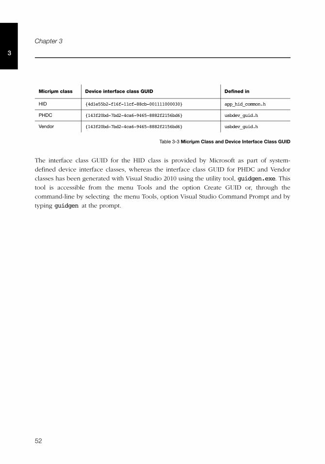
52
Chapter 3
3
Table 3-3 Micriμm Class and Device Interface Class GUID
The interface class GUID for the HID class is provided by Microsoft as part of system-
defined device interface classes, whereas the interface class GUID for PHDC and Vendor
classes has been generated with Visual Studio 2010 using the utility tool, guidgen.exe. This
tool is accessible from the menu Tools and the option Create GUID or, through the
command-line by selecting the menu Tools, option Visual Studio Command Prompt and by
typing guidgen at the prompt.
Micriμm class Device interface class GUID Defined in
HID {4d1e55b2-f16f-11cf-88cb-001111000030} app_hid_common.h
PHDC {143f20bd-7bd2-4ca6-9465-8882f2156bd6} usbdev_guid.h
Vendor {143f20bd-7bd2-4ca6-9465-8882f2156bd6} usbdev_guid.h
53
Chapter
4Architecture
μC/USB-Device was designed to be modular and easy to adapt to a variety of Central
Processing Units (CPUs), Real-Time Operating Systems (RTOS), USB device controllers, and
compilers.
Figure 4-1 shows a simplified block diagram of all the μC/USB-Device modules and their
relationships.
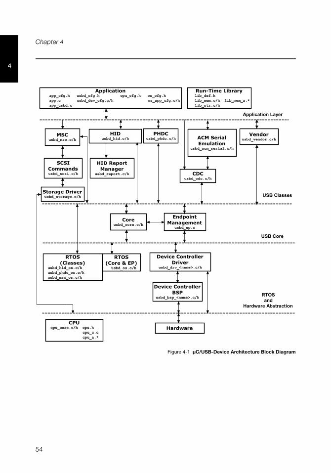
54
Chapter 4
4
Figure 4-1 μC/USB-Device Architecture Block Diagram
�������������������� �� ����� ������� ������
���� �� ����������� ���������������������� ��
�� �� �������
� �� ������� ��������
��������������� �����������
� �� �������
� ���������������
�� ��������������
����� ������
��� �� ������� ����
�� ����������
���� ��������
�������������
�� �����
������� ������������
�� ��������������
������� ���������
�� �� �����������
���������������
�� ����������
�� �! ���"���#
�� ������
�� �! ������#
�� ����������� ������������ ����������
����$���
����������
�������
-.)���
�� ����,���������
,����������'���
��%�����&�'���(����� ��������� ���������� ������������ ������
�)���������� ���
������������
55
Modules Relationship
4
4-1 MODULES RELATIONSHIP
4-1-1 APPLICATION
Your application layer needs to provide configuration information to μC/USB-Device in the
form of four C files: app_cfg.h, usbd_cfg.h, usbd_dev_cfg.c and usbd_dev_cfg.h:
■ app_cfg.h is an application-specific configuration file. It contains #defines to specify
task priorities and the stack size of each of the task within the application and the task
required by μC/USB-Device. Some small Micriμm modules like μC/LIB (run-time
library) use app_cfg.h to configure parameters such as the heap size.
■ Configuration data in usbd_cfg.h consists of specifying the number of devices
supported in the stack, the maximum number of configurations, the maximum number
of interfaces and alternate interfaces, maximum number of opened endpoints per
device, class-specific configuration parameters and more. In all, there are approximately
20 #defines to set.
■ Finally, usbd_dev_cfg.c/.h consists of device-specific configuration requirements
such as vendor ID, product ID, device release number and its respective strings. It also
contains device controller specific configurations such as base address, dedicated
memory base address and size, and endpoint management table.
Refer to Chapter 5, “Configuration” on page 65 for more information on how to configure
μC/USB-Device.
4-1-2 LIBRARIES
Given that μC/USB-Device is designed to be used in safety critical applications, some of the
“standard” library functions such as strcpy(), memset(), etc. have been rewritten to
conform to the same quality standards as the rest of the USB device stack. All these standard
functions are part of a separate Micriμm’s product, μC/LIB. μC/USB-Device depends on this
product. In addition, some data objects in USB controller drivers are created at run-time
which implies the use of memory allocation from the heap function Mem_HeapAlloc().
56
Chapter 4
4
4-1-3 USB CLASS LAYER
Your application will interface with μC/USB-Device using the class layer API. In this layer,
four classes defined by the USB-IF are implemented. In case you need to implement a
vendor-specific class, a fifth class, the “vendor” class, is available. This class provides
functions for simple communication via endpoints. The classes that μC/USB-Device
currently supports are the following:
■ Communication Device Class (CDC)
■ CDC Abstract Control Model (ACM) subclass
■ Human Interface Device Class (HID)
■ Mass Storage Class (MSC)
■ Personal Healthcare Device Class (PHDC)
■ Vendor Class
You can also create other classes defined by the USB-IF. Refer to Chapter 7, “USB Classes”
on page 99 for more information on how a USB class interacts with the core layer.
4-1-4 USB CORE LAYER
USB core layer is responsible for creating and maintaining the logical structure of a USB
device. The core layer manages the USB configurations, interfaces, alternate interfaces and
allocation of endpoints based on the application or USB classes requirements and the USB
controller endpoints available. Standard requests, bus events (reset, suspend, connect and
disconnect) and enumeration process are also handled by the Core layer.
4-1-5 ENDPOINT MANAGEMENT LAYER
The endpoint management layer is responsible for sending and receiving data using
endpoints. Control, interrupt and bulk transfers are implemented in this layer. This layer
provides synchronous API for control, bulk and interrupt I/O operations and asynchronous
API for bulk and interrupt I/O operations.
57
Modules Relationship
4
4-1-6 REAL-TIME OPERATING SYSTEM (RTOS) ABSTRACTION LAYER
μC/USB-Device assumes the presence of a RTOS, and a RTOS abstraction layer allows μC/
USB-Device to be independent of a specific RTOS. The RTOS abstraction layer is composed
of several RTOS ports, a core layer port and some class layer ports.
CORE LAYER PORT
At the very least, the RTOS for the core layer:
■ Create at least one task for the core operation and one optional task for the debug trace
feature.
■ Provide semaphore management (or the equivalent). Semaphores are used to signal
completion or error in synchronous I/O operations and trace events.
■ Provide queue management for I/O and bus events.
μC/USB-Device is provided with ports for μC/OS-II and μC/OS-III. If a different RTOS is
used, you can use the files for μC/OS-II or μC/OS-III as template to interface to the RTOS
chosen. For more information on how to port μC/USB-Device to a RTOS, see Chapter 14,
“Porting μC/USB-Device to your RTOS” on page 237.
CLASS LAYER PORTS
Some classes requires a RTOS port (i.e., MSC, PHDC and HID). Refer to Table 14-2 on
page 239 for a list of sections containing more informations on the RTOS port of each of
these classes.
4-1-7 HARDWARE ABSTRACTION LAYER
μC/USB-Device works with nearly any USB device controller. This layer handles the
specifics of the hardware, e.g., how to initialize the device, how to open and configure
endpoints, how to start reception and transmission of USB packets, how to read and write
USB packets, how to report USB events to the core, etc. The USB device driver controller
functions are encapsulated and implemented in the usbd_drv_<controller>.c file.
58
Chapter 4
4
In order to have independent configuration for clock gating, interrupt controller and general
purpose I/O, a USB device controller driver needs an additional file. This file is called a
Board Support Package (BSP). The name of this file is usbd_bsp_<controller>.c. This file
contains all the details that are closely related to the hardware on which the product is used.
This file also defines the endpoints information table. This table is used by the core layer to
allocate endpoints according to the hardware capabilities.
4-1-8 CPU LAYER
μC/USB-Device can work with either an 8, 16, 32 or even 64-bit CPU, but it must have
information about the CPU used. The CPU layer defines such information as the C data type
corresponding to 16-bit and 32-bit variables, whether the CPU has little or big endian
memory organization, and how interrupts are disabled and enabled on the CPU.
CPU-specific files are found in the \uC-CPU directory and are used to adapt μC/USB-Device
to a different CPU.
4-2 TASK MODEL
μC/USB-Device requires two tasks: One core task and one optional task for tracing debug
events. The core task has three main responsibilities:
■ Process USB bus events: Bus events such as reset, suspend, connect and disconnect are
processed by the core task. Based on the type of bus event, the core task sets the state
of the device.
■ Process USB requests: USB requests are sent by the host using the default control
endpoint. The core task processes all USB requests. Some requests are handled by the
USB class driver, for those requests the core calls the class-specific request handler.
■ Process I/O asynchronous transfers: Asynchronous I/O transfers are handled by the
core. Under completion, the core task invokes the respective callback for the transfer.
Figure 4-2 shows a simplified task model of μC/USB-Device along with application tasks.
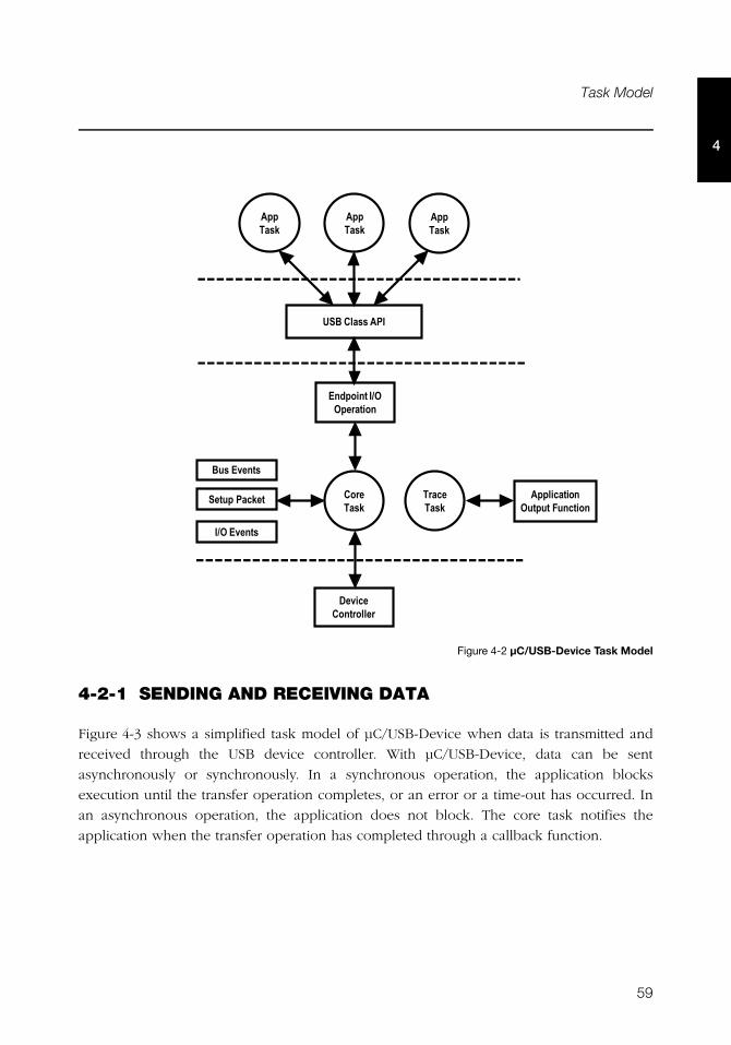
59
Task Model
4
Figure 4-2 μC/USB-Device Task Model
4-2-1 SENDING AND RECEIVING DATA
Figure 4-3 shows a simplified task model of μC/USB-Device when data is transmitted and
received through the USB device controller. With μC/USB-Device, data can be sent
asynchronously or synchronously. In a synchronous operation, the application blocks
execution until the transfer operation completes, or an error or a time-out has occurred. In
an asynchronous operation, the application does not block. The core task notifies the
application when the transfer operation has completed through a callback function.
AppTask
AppTask
AppTask
CoreTask
TraceTask
Bus Events
Endpoint I/OOperation
USB Class API
Setup Packet
I/O Events
DeviceController
ApplicationOutput Function
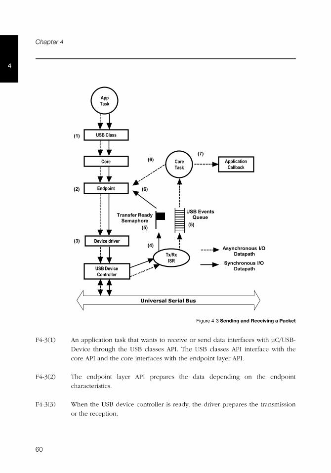
60
Chapter 4
4
Figure 4-3 Sending and Receiving a Packet
F4-3(1) An application task that wants to receive or send data interfaces with μC/USB-
Device through the USB classes API. The USB classes API interface with the
core API and the core interfaces with the endpoint layer API.
F4-3(2) The endpoint layer API prepares the data depending on the endpoint
characteristics.
F4-3(3) When the USB device controller is ready, the driver prepares the transmission
or the reception.
AppTask
USB Class
Core
Endpoint
USB DeviceController
Tx/RxISR
CoreTask
ApplicationCallback
(2)
(3)(4)
(5) (5)
(6)
(6)
(7)
USB EventsQueueTransfer Ready
Semaphore
Asynchronous I/ODatapath
Synchronous I/ODatapath
(1)
Device driver
Universal Serial Bus
61
Task Model
4
F4-3(4) Once the transfer has completed, the USB device controller generates an
interrupt. Depending of the operation (transmission or reception) the USB
device controller’s driver ISR invokes the transmit complete or receive complete
function from the core.
F4-3(5) If the operation is synchronous, the transmit or receive complete function will
signal the transfer ready counting semaphore. If the operation is asynchronous,
the transmit or receive complete function will put a message in the USB core
event queue for deferred processing by the USB core task.
F4-3(6) If the operation is synchronous, the endpoint layer will wait on the counting
semaphore. The operation repeats steps 2 to 5 until the whole transfer has
completed.
F4-3(7) The core task waits on events to be put in the core event queue. In
asynchronous transfers, the core task will call the endpoint layer until the
operation is completed.
F4-3(8) In asynchronous mode, after the transfer has completed the core task will call
the application completion callback to notify the end of the I/O operation.
4-2-2 PROCESSING USB REQUESTS AND BUS EVENTS
USB requests are processed by the core task. Figure 4-4 shows a simplified task diagram of
a USB request processing. USB bus events such as reset, resume, connect, disconnect, and
suspend are processed in the same way as the USB requests. The core process the USB bus
events to modify and update the current state of the device.
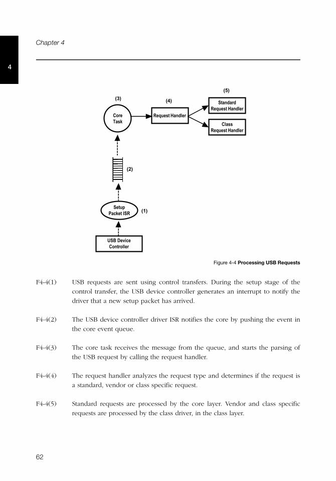
62
Chapter 4
4
Figure 4-4 Processing USB Requests
F4-4(1) USB requests are sent using control transfers. During the setup stage of the
control transfer, the USB device controller generates an interrupt to notify the
driver that a new setup packet has arrived.
F4-4(2) The USB device controller driver ISR notifies the core by pushing the event in
the core event queue.
F4-4(3) The core task receives the message from the queue, and starts the parsing of
the USB request by calling the request handler.
F4-4(4) The request handler analyzes the request type and determines if the request is
a standard, vendor or class specific request.
F4-4(5) Standard requests are processed by the core layer. Vendor and class specific
requests are processed by the class driver, in the class layer.
USB DeviceController
SetupPacket ISR
CoreTask
Request Handler
(1)
(2)
StandardRequest Handler
ClassRequest Handler
(3) (4)
(5)
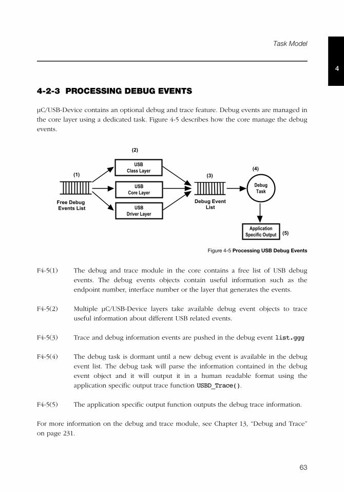
63
Task Model
4
4-2-3 PROCESSING DEBUG EVENTS
μC/USB-Device contains an optional debug and trace feature. Debug events are managed in
the core layer using a dedicated task. Figure 4-5 describes how the core manage the debug
events.
Figure 4-5 Processing USB Debug Events
F4-5(1) The debug and trace module in the core contains a free list of USB debug
events. The debug events objects contain useful information such as the
endpoint number, interface number or the layer that generates the events.
F4-5(2) Multiple μC/USB-Device layers take available debug event objects to trace
useful information about different USB related events.
F4-5(3) Trace and debug information events are pushed in the debug event list.ggg
F4-5(4) The debug task is dormant until a new debug event is available in the debug
event list. The debug task will parse the information contained in the debug
event object and it will output it in a human readable format using the
application specific output trace function USBD_Trace().
F4-5(5) The application specific output function outputs the debug trace information.
For more information on the debug and trace module, see Chapter 13, “Debug and Trace”
on page 231.
�����������
���������
/�0
�������������������������
/ 0/!0
����� ����
���� ��� ���
���$%�+����'���
/"0
�������$%+������'���
/�0

64
Chapter 4
4
65
Chapter
5Configuration
Prior to usage, μC/USB-Device must be properly configured. There are three groups of
configuration parameters:
■ Static stack configuration
■ Application specific configuration
■ Device and device controller driver configuration
This chapter explains how to setup all these groups of configuration. The last section of this
chapter also provides examples of configuration following examples of typical usage.
5-1 STATIC STACK CONFIGURATION
μC/USB-Device is configurable at compile time via approximately 20 #defines in the
application’s copy of usbd_cfg.h. μC/USB-Device uses #defines when possible because
they allow code and data sizes to be scaled at compile time based on enabled features and
the configured number of USB objects. This allows the Read-Only Memory (ROM) and
Random-Access Memory (RAM) footprints of μC/USB-Device to be adjusted based on
application requirements.
It is recommended that the configuration process begins with the recommended or default
configuration values which in the next sections will be shown in bold.
The sections in this chapter are organized following the order in μC/USB-Device’s template
configuration file, usbd_cfg.h.
66
Chapter 5
5
5-1-1 GENERIC CONFIGURATION
USBD_CFG_OPTIMIZE_SPD
Selected portions of μC/USB-Device code may be optimized for either better performance
or for smallest code size by configuring USBD_CFG_OPTIMIZE_SPD:
DEF_ENABLED Optimizes μC/USB-Device for best speed performance
DEF_DISABLED Optimizes μC/USB-Device for best binary image size
USBD_CFG_MAX_NBR_DEV
USBD_CFG_MAX_NBR_DEV configures the maximum number of devices. This value should be
set to the number of device controllers used on your platform. Default value is 1.
5-1-2 USB DEVICE CONFIGURATION
USBD_CFG_MAX_NBR_CFG
USBD_CFG_MAX_NBR_CFG sets the maximum number of USB configurations used by your
device. Keep in mind that if you use a high-speed USB device controller, you will need at
least two USB configurations, one for low and full-speed and another for high-speed. Refer
to the Universal Serial Bus specification, Revision 2.0, section 9.2.3 for more details on USB
configuration. Default value is 2.
5-1-3 INTERFACE CONFIGURATION
USBD_CFG_MAX_NBR_IF
USBD_CFG_MAX_NBR_IF configures the maximum number of interfaces available. This value
should at least be equal to USBD_CFG_MAX_NBR_CFG and greatly depends on the USB
class(es) used. Each class instance requires at least one interface, while CDC-ACM requires
two. Refer to the Universal Serial Bus specification, Revision 2.0, section 9.2.3 for more
details on USB interfaces. Default value is 2.
67
Static Stack Configuration
5USBD_CFG_MAX_NBR_IF_ALT
USBD_CFG_MAX_NBR_IF_ALT defines the maximum number of alternate interfaces (alternate
settings) available. This value should at least be equal to USBD_CFG_MAX_NBR_IF. Refer to
the Universal Serial Bus specification, Revision 2.0, section 9.2.3 for more details on
alternate settings. Default value is 2.
USBD_CFG_MAX_NBR_IF_GRP
USBD_CFG_MAX_NBR_IF_GRP sets the maximum number of interface groups or associations
available. For the moment, Micriμm offers only one USB class (CDC-ACM) that requires
interface groups. Refer to the Interface Association Descriptors USB Engineering Change
Notice for more details about interface associations. Default value is 0 (should be equal to
the number of instances of CDC-ACM).
USBD_CFG_MAX_NBR_EP_DESC
USBD_CFG_MAX_NBR_EP_DESC sets the maximum number of endpoint descriptors available.
This value greatly depends on the USB class(es) used. For information on how many
endpoints are needed for each class, refer to the class specific chapter. Keep in mind that
control endpoints do not need any endpoint descriptors. Default value is 2.
USBD_CFG_MAX_NBR_EP_OPEN
USBD_CFG_MAX_NBR_EP_OPEN configures the maximum number of opened endpoints per
device. If you use more than one device, set this value to the worst case. This value greatly
depends on the USB class(es) used. For information on how many endpoints are needed for
each class, refer to the class specific chapter. Default value is 4 (2 control plus 2 other
endpoints).
5-1-4 STRING CONFIGURATION
USBD_CFG_MAX_NBR_STR
USBD_CFG_MAX_NBR_STR configures the maximum number of string descriptors supported.
Default value is 3 (1 Manufacturer string, 1 product string and 1 serial number string). This
value can be increased if, for example, you plan to add interface specific strings.
68
Chapter 5
5
5-1-5 DEBUG CONFIGURATION
Configurations in this section only need to be set if you use the core debugging service. For
more information on that service, see Chapter 13, “Debug and Trace” on page 231.
USBD_CFG_DBG_TRACE_EN
USBD_CFG_DBG_TRACE_EN enables or disables the core debug trace engine.
DEF_ENABLED Core debug trace engine is enabled.
DEF_DISABLED Core debug trace engine is disabled.
USBD_CFG_DBG_TRACE_NBR_EVENTS
USBD_CFG_DBG_TRACE_NBR_EVENTS indicates the maximum number of debug trace events
that can be queued by the core debug trace engine. Default value is 10.
This configuration constant has no effect and will not allocate any memory if
USBD_CFG_DBG_TRACE_EN is set to DEF_DISABLED.
5-1-6 COMMUNICATION DEVICE CLASS (CDC) CONFIGURATION
For information on CDC configuration, refer to section 8-3 “Configuration” on page 120.
5-1-7 CDC ABSTRACT CONTROL MODEL (ACM) SERIAL CLASS CONFIGURATION
For information on CDC-ACM class configuration, refer to section 8-4-2 “General
Configuration” on page 123.
5-1-8 HUMAN INTERFACE DEVICE (HID) CLASS CONFIGURATION
For information on HID class configuration, refer to Section 9-3, “Configuration” on
page 143.
69
Application Specific Configuration
5
5-1-9 MASS STORAGE CLASS (MSC) CONFIGURATION
For information on MSC configuration, refer to Section 10-4, “Configuration” on page 173.
5-1-10 PERSONAL HEALTHCARE DEVICE CLASS (PHDC) CONFIGURATION
For information on PHDC configuration, refer to section 11-2 “Configuration” on page 187.
5-1-11 VENDOR CLASS CONFIGURATION
For information on vendor class configuration, refer to Section 12-2, “Configuration” on
page 207.
5-2 APPLICATION SPECIFIC CONFIGURATION
This section defines the configuration constants related to μC/USB-Device but that are
application-specific. All these configuration constants relate to the RTOS. For many OSs, the
μC/USB-Device task priorities and stack sizes will need to be explicitly configured for the
particular OS (consult the specific OS’s documentation for more information).
These configuration constants should be defined in an application’s app_cfg.h file.
5-2-1 TASK PRIORITIES
As mentioned in section 4-2 “Task Model” on page 58, μC/USB-Device needs one core task
and one optional debug task for its proper operation. The priority of μC/USB-Device’s core
task greatly depends on the USB requirements of your application. For some applications, it
might be better to set it at a high priority, especially if your application requires a lot of
tasks and is CPU intensive. In that case, if the core task has a low priority, it might not be
able to process the bus and control requests on time. On the other hand, for some
applications, you might want to give the core task a low priority, especially if you plan using
asynchronous communication and if you know you will have quite a lot of code in your
callback functions. For more information on the core task, see section 4-2 “Task Model” on
page 58.
70
Chapter 5
5The priority of the debug task should generally be low since it is not critical and the task
performed can be executed in the background.
For the μC/OS-II and μC/OS-III RTOS ports, the following macros must be configured
within app_cfg.h:
■ USBD_OS_CFG_CORE_TASK_PRIO
■ USBD_OS_CFG_TRACE_TASK_PRIO
Note: if USBD_CFG_DBG_TRACE_EN is set to DEF_DISABLED, USBD_OS_CFG_TRACE_TASK_PRIO
should not be defined.
5-2-2 TASK STACK SIZES
For the μC/OS-II and μC/OS-III RTOS ports, the following macros must be configured
within app_cfg.h to set the internal task stack sizes:
■ USBD_OS_CFG_CORE_TASK_STK_SIZE 1000
■ USBD_OS_CFG_TRACE_TASK_STK_SIZE 1000
Note: if USBD_CFG_DBG_TRACE_EN is set to DEF_DISABLED, USBD_OS_CFG_TRACE_TASK_STK_SIZE
should not be defined.
The arbitrary stack size of 1000 is a good starting point for most applications.
The only guaranteed method of determining the required task stack sizes is to calculate the
maximum stack usage for each task. Obviously, the maximum stack usage for a task is the
total stack usage along the task’s most-stack-greedy function path plus the (maximum) stack
usage for interrupts. Note that the most-stack-greedy function path is not necessarily the
longest or deepest function path.
The easiest and best method for calculating the maximum stack usage for any task/function
should be performed statically by the compiler or by a static analysis tool since these can
calculate function/task maximum stack usage based on the compiler’s actual code
generation and optimization settings. So for optimal task stack configuration, we
recommend to invest in a task stack calculator tool compatible with your build toolchain.
71
Device and Device Controller Driver Configuration
5
5-3 DEVICE AND DEVICE CONTROLLER DRIVER CONFIGURATION
In order to finalize the configuration of your device, you need to declare two structures, one
will contain information about your device (Vendor ID, Product ID, etc.) and another that
will contain information useful to the device controller driver. A reference to both of these
structures needs to be passed to the USBD_DevAdd() function, which allocates a device
controller.
For more information on how to modify device and device controller driver configuration,
see section 2-4-2 “Copying and Modifying Template Files” on page 33.
5-4 CONFIGURATION EXAMPLES
This section provides examples of configuration for μC/USB-Device stack based on some
typical usages. This section will only give examples of static stack configuration, as the
application-specific configuration greatly depends on your application. Also, the device
configuration is related to your product’s context, and the device controller driver
configuration depends on the hardware you use.
The examples of typical usage that will be treated are the following:
■ A simple full-speed USB device. This device uses Micriμm’s vendor class.
■ A composite high-speed USB device. This device uses Micriμm’s PHDC and MSC
classes.
■ A complex composite high-speed USB device. This device uses an instance of Micriμm’s
HID class in two different configurations plus a different instance of Micriμm’s CDC-
ACM class in each configuration. This device also uses an instance of Micriμm’s vendor
class in the second configuration.
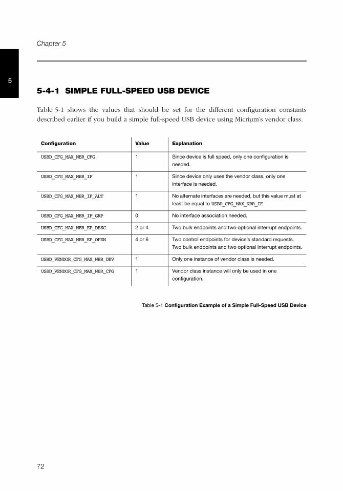
72
Chapter 5
5
5-4-1 SIMPLE FULL-SPEED USB DEVICE
Table 5-1 shows the values that should be set for the different configuration constants
described earlier if you build a simple full-speed USB device using Micriμm’s vendor class.
Table 5-1 Configuration Example of a Simple Full-Speed USB Device
Configuration Value Explanation
USBD_CFG_MAX_NBR_CFG 1 Since device is full speed, only one configuration is
needed.
USBD_CFG_MAX_NBR_IF 1 Since device only uses the vendor class, only one
interface is needed.
USBD_CFG_MAX_NBR_IF_ALT 1 No alternate interfaces are needed, but this value must at
least be equal to USBD_CFG_MAX_NBR_IF.
USBD_CFG_MAX_NBR_IF_GRP 0 No interface association needed.
USBD_CFG_MAX_NBR_EP_DESC 2 or 4 Two bulk endpoints and two optional interrupt endpoints.
USBD_CFG_MAX_NBR_EP_OPEN 4 or 6 Two control endpoints for device’s standard requests.
Two bulk endpoints and two optional interrupt endpoints.
USBD_VENDOR_CFG_MAX_NBR_DEV 1 Only one instance of vendor class is needed.
USBD_VENDOR_CFG_MAX_NBR_CFG 1 Vendor class instance will only be used in one
configuration.
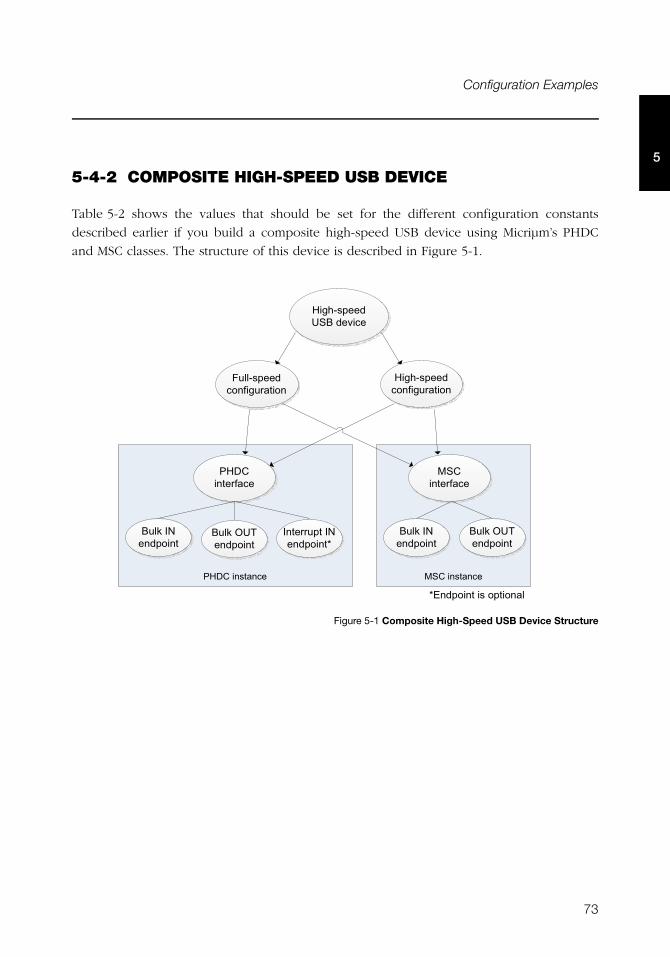
73
Configuration Examples
5
5-4-2 COMPOSITE HIGH-SPEED USB DEVICE
Table 5-2 shows the values that should be set for the different configuration constants
described earlier if you build a composite high-speed USB device using Micriμm’s PHDC
and MSC classes. The structure of this device is described in Figure 5-1.
Figure 5-1 Composite High-Speed USB Device Structure
�+#� '�� � �)�+#� '�� �
)�&0,'� %#��!#% $��
"��,'� %#�� ��&�����
)�&0,'� %#�� ��&�����
�)�+� � ����
�+� � ����
!�1#�� %��� �
!�1#��� %��� �
!�1#�� %��� �
� � ����#�� %��� �2
!�1#��� %��� �
2� %��� �#�'#����� ��
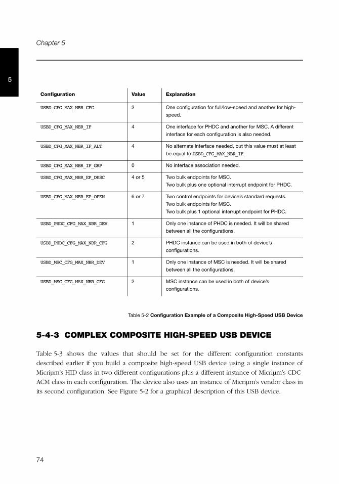
74
Chapter 5
5
Table 5-2 Configuration Example of a Composite High-Speed USB Device
5-4-3 COMPLEX COMPOSITE HIGH-SPEED USB DEVICE
Table 5-3 shows the values that should be set for the different configuration constants
described earlier if you build a composite high-speed USB device using a single instance of
Micriμm’s HID class in two different configurations plus a different instance of Micriμm’s CDC-
ACM class in each configuration. The device also uses an instance of Micriμm’s vendor class in
its second configuration. See Figure 5-2 for a graphical description of this USB device.
Configuration Value Explanation
USBD_CFG_MAX_NBR_CFG 2 One configuration for full/low-speed and another for high-
speed.
USBD_CFG_MAX_NBR_IF 4 One interface for PHDC and another for MSC. A different
interface for each configuration is also needed.
USBD_CFG_MAX_NBR_IF_ALT 4 No alternate interface needed, but this value must at least
be equal to USBD_CFG_MAX_NBR_IF.
USBD_CFG_MAX_NBR_IF_GRP 0 No interface association needed.
USBD_CFG_MAX_NBR_EP_DESC 4 or 5 Two bulk endpoints for MSC.
Two bulk plus one optional interrupt endpoint for PHDC.
USBD_CFG_MAX_NBR_EP_OPEN 6 or 7 Two control endpoints for device’s standard requests.
Two bulk endpoints for MSC.
Two bulk plus 1 optional interrupt endpoint for PHDC.
USBD_PHDC_CFG_MAX_NBR_DEV 1 Only one instance of PHDC is needed. It will be shared
between all the configurations.
USBD_PHDC_CFG_MAX_NBR_CFG 2 PHDC instance can be used in both of device’s
configurations.
USBD_MSC_CFG_MAX_NBR_DEV 1 Only one instance of MSC is needed. It will be shared
between all the configurations.
USBD_MSC_CFG_MAX_NBR_CFG 2 MSC instance can be used in both of device’s
configurations.
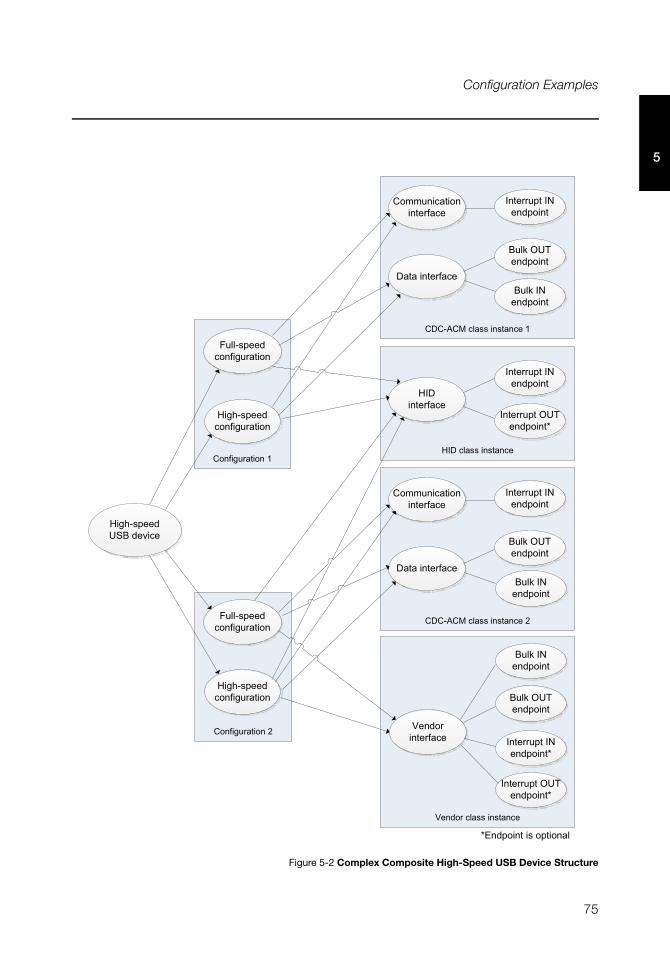
75
Configuration Examples
5
Figure 5-2 Complex Composite High-Speed USB Device Structure
+� ��&����� #�
+� ��&����� #/
)��#���''#� '�� �
)�&0,'� %#��!#% $��
"��,'� %#�� ��&�����
)�&0,'� %#�� ��&�����
)��� � ����
� � ����#�� %��� �
� � ����#��� %��� �2
2� %��� �#�'#����� ��
"��,'� %#�� ��&�����
)�&0,'� %#�� ��&�����
+�+,�+#���''#� '�� � #�
+��� ������ � � ����
!�1#�� %��� �
� � ����#�� %��� �
!�1#��� %��� �
����#� � ����
+�+,�+#���''#� '�� � #/
+��� ������ � � ����
!�1#�� %��� �
� � ����#�� %��� �
!�1#��� %��� �
����#� � ����
3 %��#���''#� '�� �
3 %��� � ���� � � ����#��
%��� �2
� � ����#��� %��� �2
!�1#�� %��� �
!�1#��� %��� �
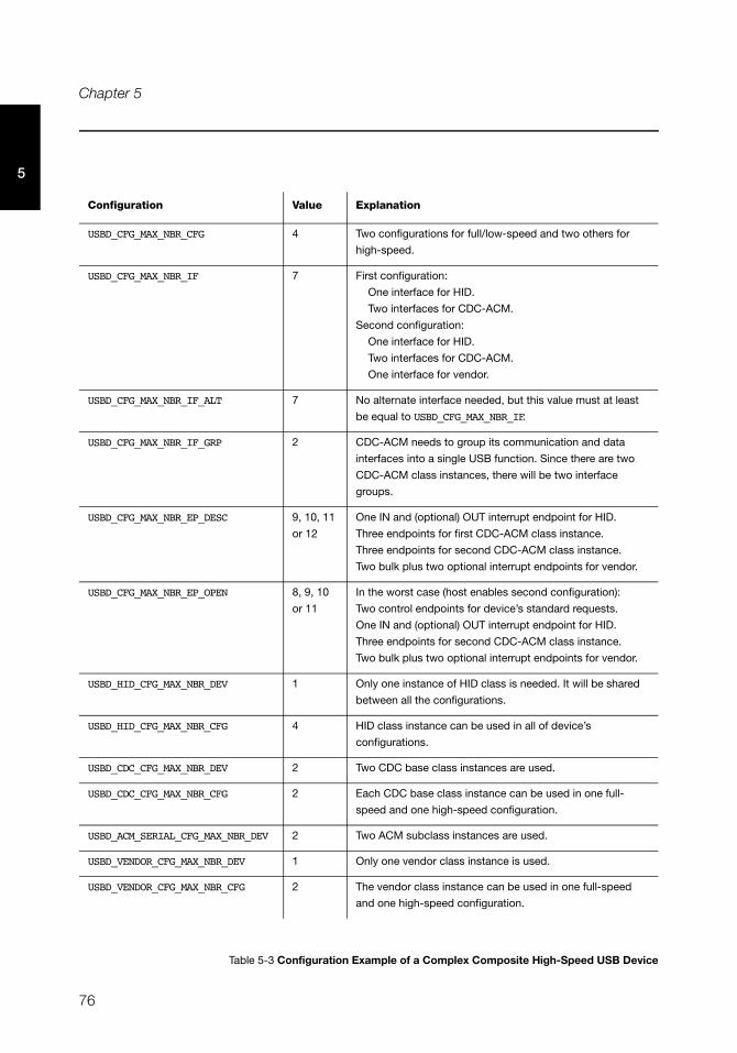
76
Chapter 5
5
Table 5-3 Configuration Example of a Complex Composite High-Speed USB Device
Configuration Value Explanation
USBD_CFG_MAX_NBR_CFG 4 Two configurations for full/low-speed and two others for
high-speed.
USBD_CFG_MAX_NBR_IF 7 First configuration:
One interface for HID.
Two interfaces for CDC-ACM.
Second configuration:
One interface for HID.
Two interfaces for CDC-ACM.
One interface for vendor.
USBD_CFG_MAX_NBR_IF_ALT 7 No alternate interface needed, but this value must at least
be equal to USBD_CFG_MAX_NBR_IF.
USBD_CFG_MAX_NBR_IF_GRP 2 CDC-ACM needs to group its communication and data
interfaces into a single USB function. Since there are two
CDC-ACM class instances, there will be two interface
groups.
USBD_CFG_MAX_NBR_EP_DESC 9, 10, 11
or 12
One IN and (optional) OUT interrupt endpoint for HID.
Three endpoints for first CDC-ACM class instance.
Three endpoints for second CDC-ACM class instance.
Two bulk plus two optional interrupt endpoints for vendor.
USBD_CFG_MAX_NBR_EP_OPEN 8, 9, 10
or 11
In the worst case (host enables second configuration):
Two control endpoints for device’s standard requests.
One IN and (optional) OUT interrupt endpoint for HID.
Three endpoints for second CDC-ACM class instance.
Two bulk plus two optional interrupt endpoints for vendor.
USBD_HID_CFG_MAX_NBR_DEV 1 Only one instance of HID class is needed. It will be shared
between all the configurations.
USBD_HID_CFG_MAX_NBR_CFG 4 HID class instance can be used in all of device’s
configurations.
USBD_CDC_CFG_MAX_NBR_DEV 2 Two CDC base class instances are used.
USBD_CDC_CFG_MAX_NBR_CFG 2 Each CDC base class instance can be used in one full-
speed and one high-speed configuration.
USBD_ACM_SERIAL_CFG_MAX_NBR_DEV 2 Two ACM subclass instances are used.
USBD_VENDOR_CFG_MAX_NBR_DEV 1 Only one vendor class instance is used.
USBD_VENDOR_CFG_MAX_NBR_CFG 2 The vendor class instance can be used in one full-speed
and one high-speed configuration.
77
Chapter
6Device Driver Guide
There are many USB device controllers available on the market and each requires a driver to
work with μC/USB-Device. The amount of code necessary to port a specific device to μC/
USB-Device greatly depends on the device’s complexity.
If not already available, a driver can be developed, as described in this chapter. However, it
is recommended to modify an already existing device driver with the new device’s specific
code following the Micriμm coding convention for consistency. It is also possible to adapt
drivers written for other USB device stacks, especially if the driver is short and it is a matter
of simply copying data to and from the device.
6-1 DEVICE DRIVER ARCHITECTURE
This section describes the hardware (device) driver architecture for μC/USB-Device,
including:
■ Device Driver API Definition(s)
■ Device Configuration
■ Memory Allocation
■ CPU and Board Support
Micriμm provides sample configuration code free of charge; however, the sample code will
likely require modification depending on the combination of processor, evaluation board,
and USB device controller(s).
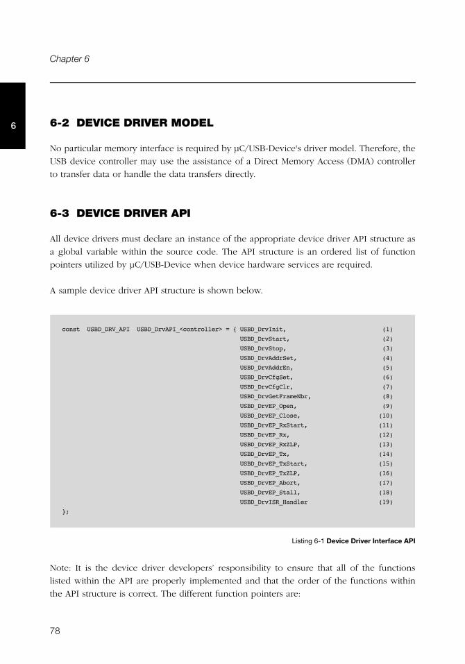
78
Chapter 6
6 6-2 DEVICE DRIVER MODEL
No particular memory interface is required by μC/USB-Device's driver model. Therefore, the
USB device controller may use the assistance of a Direct Memory Access (DMA) controller
to transfer data or handle the data transfers directly.
6-3 DEVICE DRIVER API
All device drivers must declare an instance of the appropriate device driver API structure as
a global variable within the source code. The API structure is an ordered list of function
pointers utilized by μC/USB-Device when device hardware services are required.
A sample device driver API structure is shown below.
Listing 6-1 Device Driver Interface API
Note: It is the device driver developers’ responsibility to ensure that all of the functions
listed within the API are properly implemented and that the order of the functions within
the API structure is correct. The different function pointers are:
const USBD_DRV_API USBD_DrvAPI_<controller> = { USBD_DrvInit, (1)
USBD_DrvStart, (2)
USBD_DrvStop, (3)
USBD_DrvAddrSet, (4)
USBD_DrvAddrEn, (5)
USBD_DrvCfgSet, (6)
USBD_DrvCfgClr, (7)
USBD_DrvGetFrameNbr, (8)
USBD_DrvEP_Open, (9)
USBD_DrvEP_Close, (10)
USBD_DrvEP_RxStart, (11)
USBD_DrvEP_Rx, (12)
USBD_DrvEP_RxZLP, (13)
USBD_DrvEP_Tx, (14)
USBD_DrvEP_TxStart, (15)
USBD_DrvEP_TxZLP, (16)
USBD_DrvEP_Abort, (17)
USBD_DrvEP_Stall, (18)
USBD_DrvISR_Handler (19)
};
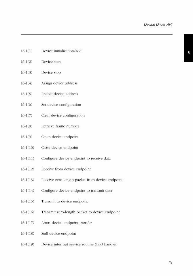
79
Device Driver API
6L6-1(1) Device initialization/add
L6-1(2) Device start
L6-1(3) Device stop
L6-1(4) Assign device address
L6-1(5) Enable device address
L6-1(6) Set device configuration
L6-1(7) Clear device configuration
L6-1(8) Retrieve frame number
L6-1(9) Open device endpoint
L6-1(10) Close device endpoint
L6-1(11) Configure device endpoint to receive data
L6-1(12) Receive from device endpoint
L6-1(13) Receive zero-length packet from device endpoint
L6-1(14) Configure device endpoint to transmit data
L6-1(15) Transmit to device endpoint
L6-1(16) Transmit zero-length packet to device endpoint
L6-1(17) Abort device endpoint transfer
L6-1(18) Stall device endpoint
L6-1(19) Device interrupt service routine (ISR) handler
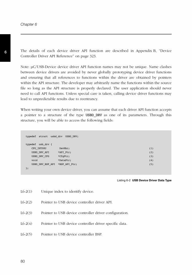
80
Chapter 6
6 The details of each device driver API function are described in Appendix B, “Device
Controller Driver API Reference” on page 323.
Note: μC/USB-Device device driver API function names may not be unique. Name clashes
between device drivers are avoided by never globally prototyping device driver functions
and ensuring that all references to functions within the driver are obtained by pointers
within the API structure. The developer may arbitrarily name the functions within the source
file so long as the API structure is properly declared. The user application should never
need to call API functions. Unless special care is taken, calling device driver functions may
lead to unpredictable results due to reentrancy.
When writing your own device driver, you can assume that each driver API function accepts
a pointer to a structure of the type USBD_DRV as one of its parameters. Through this
structure, you will be able to access the following fields:
Listing 6-2 USB Device Driver Data Type
L6-2(1) Unique index to identify device.
L6-2(2) Pointer to USB device controller driver API.
L6-2(3) Pointer to USB device controller driver configuration.
L6-2(4) Pointer to USB device controller driver specific data.
L6-2(5) Pointer to USB device controller BSP.
typedef struct usbd_drv USBD_DRV;
typedef usb_drv {
CPU_INT08U DevNbr; (1)
USBD_DRV_API *API_Ptr; (2)
USBD_DRV_CFG *CfgPtr; (3)
void *DataPtr; (4)
USBD_DRV_BSP_API *BSP_API_Ptr; (5)
};
81
Interrupt Handling
66-4 INTERRUPT HANDLING
Interrupt handling is accomplished using the following multi-level scheme.
1 Processor level kernel-aware interrupt handler
2 Device driver interrupt handler
During initialization, the device driver registers all necessary interrupt sources with the BSP
interrupt management code. You can also accomplish this by plugging an interrupt vector
table during compile time. Once the global interrupt vector sources are configured and an
interrupt occurs, the system will call the first-level interrupt handler. The first-level interrupt
handler is responsible for performing all kernel required steps prior to calling the USB
device driver interrupt handler: USBD_DrvISR_Handler(). Depending on the platform
architecture (that is the way the kernel handles interrupts) and the USB device controller
interrupt vectors, the device driver interrupt handler implementation may follow the models
below.
6-4-1 SINGLE USB ISR VECTOR WITH ISR HANDLER ARGUMENT
If the platform architecture allows parameters to be passed to ISR handlers and the USB
device controller has a single interrupt vector for the USB device, the first-level interrupt
handler may be defined as:
PROTOTYPE
void USBD_BSP_<controller>_IntHandler (void *p_arg);
ARGUMENTS
p_arg Pointer to USB device driver structure that must be typecast to a pointer to
USBD_DRV.
82
Chapter 6
6 6-4-2 SINGLE USB ISR VECTOR
If the platform architecture does not allow parameters to be passed to ISR handlers and the
USB device controller has a single interrupt vector for the USB device, the first-level
interrupt handler may be defined as:
PROTOTYPE
void USBD_BSP_<controller>_IntHandler (void);
ARGUMENTS
None.
NOTES / WARNINGS
In this configuration, the pointer to the USB device driver structure must be stored globally
in the driver. Since the pointer to the USB device structure is never modified, the BSP
initialization function, USBD_BSP_Init(), can save its address for later use.
6-4-3 MULTIPLE USB ISR VECTORS WITH ISR HANDLER ARGUMENTS
If the platform architecture allows parameters to be passed to ISR handlers and the USB
device controller has multiple interrupt vectors for the USB device (e.g., USB events, DMA
transfers), the first-level interrupt handler may need to be split into multiple sub-handlers.
Each sub-handler would be responsible for managing the status reported to the different
vectors. For example, the first-level interrupt handlers for a USB device controller that
redirects USB events to one interrupt vector and the status of DMA transfers to a second
interrupt vector may be defined as:
PROTOTYPE
void USBD_BSP_<controller>_EventIntHandler (void *p_arg);
void USBD_BSP_<controller>_DMAIntHandler (void *p_arg);
ARGUMENTS
p_arg Pointer to USB device driver structure that must be typecast to a pointer to
USBD_DRV.
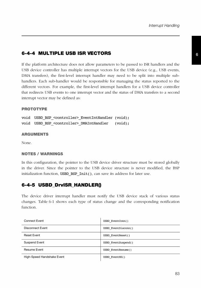
83
Interrupt Handling
66-4-4 MULTIPLE USB ISR VECTORS
If the platform architecture does not allow parameters to be passed to ISR handlers and the
USB device controller has multiple interrupt vectors for the USB device (e.g., USB events,
DMA transfers), the first-level interrupt handler may need to be split into multiple sub-
handlers. Each sub-handler would be responsible for managing the status reported to the
different vectors. For example, the first-level interrupt handlers for a USB device controller
that redirects USB events to one interrupt vector and the status of DMA transfers to a second
interrupt vector may be defined as:
PROTOTYPE
void USBD_BSP_<controller>_EventIntHandler (void);
void USBD_BSP_<controller>_DMAIntHandler (void);
ARGUMENTS
None.
NOTES / WARNINGS
In this configuration, the pointer to the USB device driver structure must be stored globally
in the driver. Since the pointer to the USB device structure is never modified, the BSP
initialization function, USBD_BSP_Init(), can save its address for later use.
6-4-5 USBD_DrvISR_HANDLER()
The device driver interrupt handler must notify the USB device stack of various status
changes. Table 6-1 shows each type of status change and the corresponding notification
function.
Connect Event USBD_EventConn()
Disconnect Event USBD_EventDisconn()
Reset Event USBD_EventReset()
Suspend Event USBD_EventSuspend()
Resume Event USBD_EventResume()
High-Speed Handshake Event USBD_EventHS()

84
Chapter 6
6
Table 6-1 Status Notification API
Each status notification API queues the event type to be processed by the USB stack’s event
processing task. Upon reception of an USB event, the interrupt service routine may perform
some operations associated to the event before notifying the stack. For example, the USB
device controller driver must perform the proper actions for the bus reset when an interrupt
request for that event is triggered. Additionally, it must also notify the USB device stack
about the bus reset event by invoking the proper status notification API. In general, the
device driver interrupt handler must perform the following functions:
1 Determine which type of interrupt event occurred by reading an interrupt status
register.
2 If a receive event has occurred, the driver must post the successful completion or the
error status to the USB device stack by calling USBD_EP_RxCmpl() for each transfer
received.
3 If a transmit complete event has occurred, the driver must post the successful
completion or the error status to the USB device stack by calling USBD_EP_TxCmpl() for
each transfer transmitted.
4 If a setup packet event has occurred, the driver must post the setup packet data in little-
endian format to the USB device stack by calling USBD_EventSetup().
5 All other events must be posted to the USB device stack by a call to their corresponding
status notification API from Table 1. This allows the USB device stack to broadcast these
event notifications to the classes.
6 Clear local interrupt flags.
Setup Packet USBD_EventSetup()
Receive Packet Completed USBD_EP_RxCmpl()
Transmit Packet Completed USBD_EP_TxCmpl()
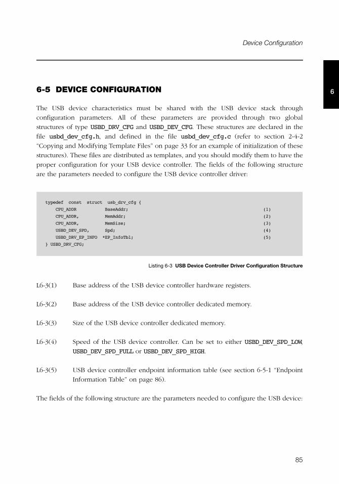
85
Device Configuration
66-5 DEVICE CONFIGURATION
The USB device characteristics must be shared with the USB device stack through
configuration parameters. All of these parameters are provided through two global
structures of type USBD_DRV_CFG and USBD_DEV_CFG. These structures are declared in the
file usbd_dev_cfg.h, and defined in the file usbd_dev_cfg.c (refer to section 2-4-2
“Copying and Modifying Template Files” on page 33 for an example of initialization of these
structures). These files are distributed as templates, and you should modify them to have the
proper configuration for your USB device controller. The fields of the following structure
are the parameters needed to configure the USB device controller driver:
Listing 6-3 USB Device Controller Driver Configuration Structure
L6-3(1) Base address of the USB device controller hardware registers.
L6-3(2) Base address of the USB device controller dedicated memory.
L6-3(3) Size of the USB device controller dedicated memory.
L6-3(4) Speed of the USB device controller. Can be set to either USBD_DEV_SPD_LOW,
USBD_DEV_SPD_FULL or USBD_DEV_SPD_HIGH.
L6-3(5) USB device controller endpoint information table (see section 6-5-1 “Endpoint
Information Table” on page 86).
The fields of the following structure are the parameters needed to configure the USB device:
typedef const struct usb_drv_cfg {
CPU_ADDR BaseAddr; (1)
CPU_ADDR, MemAddr; (2)
CPU_ADDR, MemSize; (3)
USBD_DEV_SPD, Spd; (4)
USBD_DRV_EP_INFO *EP_InfoTbl; (5)
} USBD_DRV_CFG;
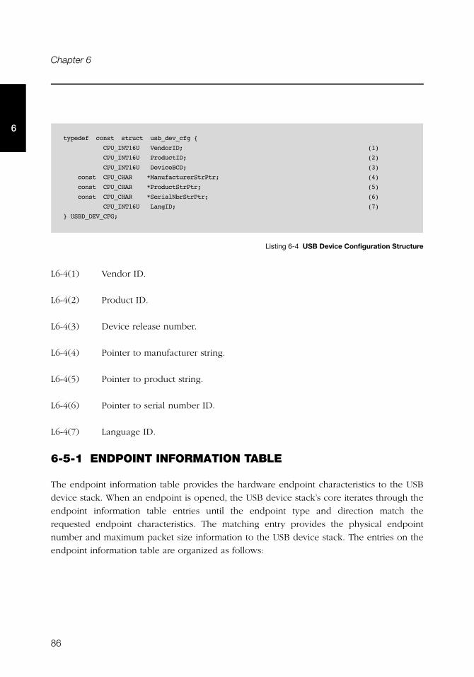
86
Chapter 6
6
Listing 6-4 USB Device Configuration Structure
L6-4(1) Vendor ID.
L6-4(2) Product ID.
L6-4(3) Device release number.
L6-4(4) Pointer to manufacturer string.
L6-4(5) Pointer to product string.
L6-4(6) Pointer to serial number ID.
L6-4(7) Language ID.
6-5-1 ENDPOINT INFORMATION TABLE
The endpoint information table provides the hardware endpoint characteristics to the USB
device stack. When an endpoint is opened, the USB device stack’s core iterates through the
endpoint information table entries until the endpoint type and direction match the
requested endpoint characteristics. The matching entry provides the physical endpoint
number and maximum packet size information to the USB device stack. The entries on the
endpoint information table are organized as follows:
typedef const struct usb_dev_cfg {
CPU_INT16U VendorID; (1)
CPU_INT16U ProductID; (2)
CPU_INT16U DeviceBCD; (3)
const CPU_CHAR *ManufacturerStrPtr; (4)
const CPU_CHAR *ProductStrPtr; (5)
const CPU_CHAR *SerialNbrStrPtr; (6)
CPU_INT16U LangID; (7)
} USBD_DEV_CFG;
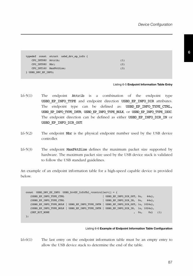
87
Device Configuration
6
Listing 6-5 Endpoint Information Table Entry
L6-5(1) The endpoint Attrib is a combination of the endpoint type
USBD_EP_INFO_TYPE and endpoint direction USBD_EP_INFO_DIR attributes.
The endpoint type can be defined as: USBD_EP_INFO_TYPE_CTRL,
USBD_EP_INFO_TYPE_INTR, USBD_EP_INFO_TYPE_BULK, or USBD_EP_INFO_TYPE_ISOC.
The endpoint direction can be defined as either USBD_EP_INFO_DIR_IN or
USBD_EP_INFO_DIR_OUT.
L6-5(2) The endpoint Nbr is the physical endpoint number used by the USB device
controller.
L6-5(3) The endpoint MaxPktSize defines the maximum packet size supported by
hardware. The maximum packet size used by the USB device stack is validated
to follow the USB standard guidelines.
An example of an endpoint information table for a high-speed capable device is provided
below.
Listing 6-6 Example of Endpoint Information Table Configuration
L6-6(1) The last entry on the endpoint information table must be an empty entry to
allow the USB device stack to determine the end of the table.
typedef const struct usbd_drv_ep_info {
CPU_INT08U Attrib; (1)
CPU_INT08U Nbr; (2)
CPU_INT16U MaxPktSize; (3)
} USBD_DRV_EP_INFO;
const USBD_DRV_EP_INFO USBD_DrvEP_InfoTbl_<controller>[] = {
{USBD_EP_INFO_TYPE_CTRL | USBD_EP_INFO_DIR_OUT, 0u, 64u},
{USBD_EP_INFO_TYPE_CTRL | USBD_EP_INFO_DIR_IN, 0u, 64u},
{USBD_EP_INFO_TYPE_BULK | USBD_EP_INFO_TYPE_INTR | USBD_EP_INFO_DIR_OUT, 1u, 1024u},
{USBD_EP_INFO_TYPE_BULK | USBD_EP_INFO_TYPE_INTR | USBD_EP_INFO_DIR_IN, 1u, 1024u},
{DEF_BIT_NONE , 0u, 0u} (1)
};
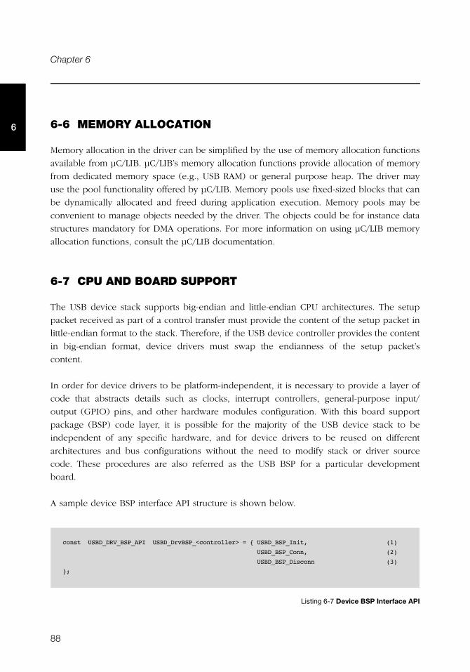
88
Chapter 6
6 6-6 MEMORY ALLOCATION
Memory allocation in the driver can be simplified by the use of memory allocation functions
available from μC/LIB. μC/LIB’s memory allocation functions provide allocation of memory
from dedicated memory space (e.g., USB RAM) or general purpose heap. The driver may
use the pool functionality offered by μC/LIB. Memory pools use fixed-sized blocks that can
be dynamically allocated and freed during application execution. Memory pools may be
convenient to manage objects needed by the driver. The objects could be for instance data
structures mandatory for DMA operations. For more information on using μC/LIB memory
allocation functions, consult the μC/LIB documentation.
6-7 CPU AND BOARD SUPPORT
The USB device stack supports big-endian and little-endian CPU architectures. The setup
packet received as part of a control transfer must provide the content of the setup packet in
little-endian format to the stack. Therefore, if the USB device controller provides the content
in big-endian format, device drivers must swap the endianness of the setup packet’s
content.
In order for device drivers to be platform-independent, it is necessary to provide a layer of
code that abstracts details such as clocks, interrupt controllers, general-purpose input/
output (GPIO) pins, and other hardware modules configuration. With this board support
package (BSP) code layer, it is possible for the majority of the USB device stack to be
independent of any specific hardware, and for device drivers to be reused on different
architectures and bus configurations without the need to modify stack or driver source
code. These procedures are also referred as the USB BSP for a particular development
board.
A sample device BSP interface API structure is shown below.
Listing 6-7 Device BSP Interface API
const USBD_DRV_BSP_API USBD_DrvBSP_<controller> = { USBD_BSP_Init, (1)
USBD_BSP_Conn, (2)
USBD_BSP_Disconn (3)
};
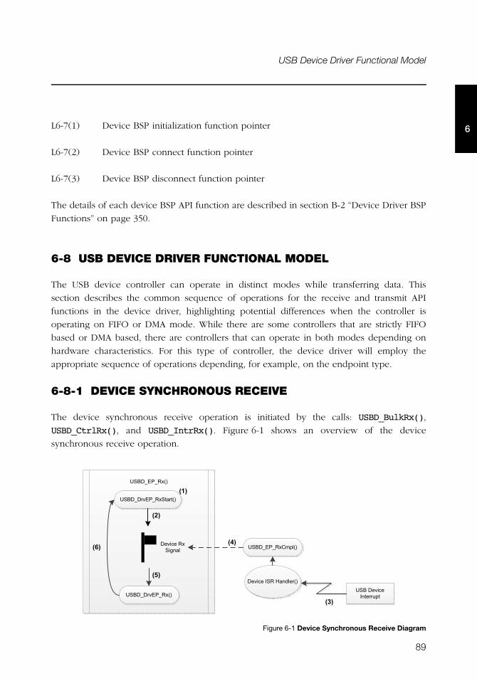
89
USB Device Driver Functional Model
6L6-7(1) Device BSP initialization function pointer
L6-7(2) Device BSP connect function pointer
L6-7(3) Device BSP disconnect function pointer
The details of each device BSP API function are described in section B-2 “Device Driver BSP
Functions” on page 350.
6-8 USB DEVICE DRIVER FUNCTIONAL MODEL
The USB device controller can operate in distinct modes while transferring data. This
section describes the common sequence of operations for the receive and transmit API
functions in the device driver, highlighting potential differences when the controller is
operating on FIFO or DMA mode. While there are some controllers that are strictly FIFO
based or DMA based, there are controllers that can operate in both modes depending on
hardware characteristics. For this type of controller, the device driver will employ the
appropriate sequence of operations depending, for example, on the endpoint type.
6-8-1 DEVICE SYNCHRONOUS RECEIVE
The device synchronous receive operation is initiated by the calls: USBD_BulkRx(),
USBD_CtrlRx(), and USBD_IntrRx(). Figure 6-1 shows an overview of the device
synchronous receive operation.
Figure 6-1 Device Synchronous Receive Diagram
����������
������ ������� ���
������ ������
��������������
���
���
���
���
��������������� ���
���������������� ��
��������������
���
��
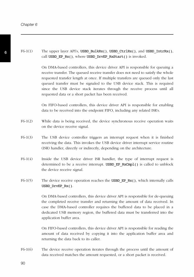
90
Chapter 6
6 F6-1(1) The upper layer API’s, USBD_BulkRx(), USBD_CtrlRx(), and USBD_IntrRx(),
call USBD_EP_Rx(), where USBD_DrvEP_RxStart() is invoked.
On DMA-based controllers, this device driver API is responsible for queuing a
receive transfer. The queued receive transfer does not need to satisfy the whole
requested transfer length at once. If multiple transfers are queued only the last
queued transfer must be signaled to the USB device stack. This is required
since the USB device stack iterates through the receive process until all
requested data or a short packet has been received.
On FIFO-based controllers, this device driver API is responsible for enabling
data to be received into the endpoint FIFO, including any related ISR’s.
F6-1(2) While data is being received, the device synchronous receive operation waits
on the device receive signal.
F6-1(3) The USB device controller triggers an interrupt request when it is finished
receiving the data. This invokes the USB device driver interrupt service routine
(ISR) handler, directly or indirectly, depending on the architecture.
F6-1(4) Inside the USB device driver ISR handler, the type of interrupt request is
determined to be a receive interrupt. USBD_EP_RxCmpl() is called to unblock
the device receive signal.
F6-1(5) The device receive operation reaches the USBD_EP_Rx(), which internally calls
USBD_DrvEP_Rx().
On DMA-based controllers, this device driver API is responsible for de-queuing
the completed receive transfer and returning the amount of data received. In
case the DMA-based controller requires the buffered data to be placed in a
dedicated USB memory region, the buffered data must be transferred into the
application buffer area.
On FIFO-based controllers, this device driver API is responsible for reading the
amount of data received by copying it into the application buffer area and
returning the data back to its caller.
F6-1(6) The device receive operation iterates through the process until the amount of
data received matches the amount requested, or a short packet is received.
91
USB Device Driver Functional Model
66-8-2 DEVICE ASYNCHRONOUS RECEIVE
The device asynchronous receive operation is initiated by the calls: USBD_BulkRxAsync()
and USBD_IntrRxAsync(). Figure 6-2 shows an overview of the device asynchronous
receive operation.
Figure 6-2 Device Asynchronous Receive Diagram
F6-2(1) The upper layer API’s, USBD_BulkRxAsync() and USBD_IntrRxAsync(), call
USBD_EP_Rx() passing a receive complete callback function as an argument. In
USBD_EP_Rx(), the USBD_DrvEP_RxStart() function is invoked in the same
way as for the synchronous operation.
On DMA-based controllers, this device driver API is responsible for queuing a
receive transfer. The queued receive transfer does not need to satisfy the whole
requested transfer length at once. If multiple transfers are queued only the last
queued transfer must be signaled to the USB device stack. This is required
since the USB device stack iterates through the receive process until all
requested data or a short packet has been received.
On FIFO-based controllers, this device driver API is responsible for enabling
data to be received into the endpoint FIFO, including any related ISRs.
The call to USBD_EP_Rx() returns immediately to the application (without
blocking) while data is being received.
����������
������ ������� ���
���
��������������� ���
���������������� ��
��������������
���
����� �� �!"
������ ������
������ ������� ���
��������������������#��"
��
���
���
���$����
92
Chapter 6
6 F6-2(2) The USB device controller triggers an interrupt request when it is finished
receiving the data. This invokes the USB device driver interrupt service routine
(ISR) handler, directly or indirectly, depending on the architecture.
F6-2(3) Inside the USB device driver ISR handler, the type of interrupt request is
determined to be a receive interrupt. USBD_EP_RxCmpl() is called to queue the
endpoint that had its transfer completed.
F6-2(4) The core task de-queues the endpoint that completed a transfer and invokes
USBD_EP_Process(), which internally calls USBD_DrvEP_Rx().
On DMA-based controllers, this device driver API is responsible for de-queuing
the completed receive transfer and returning the amount of data received. In
case the DMA-based controller requires the buffered data to be placed in a
dedicated USB memory region, the buffered data must be transferred into the
application buffer area.
On FIFO-based controllers, this device driver API is responsible for reading the
amount of data received by copying it into the application buffer area and
returning the data back to its caller.
F6-2(5) If the overall amount of data received is less than the amount requested and
the current transfer is not a short packet, USBD_DrvEP_RxStart() is called to
request the remaining data.
On DMA-based controllers, this device driver API is responsible for queuing a
receive transfer. The queued receive transfer does not need to satisfy the whole
requested transfer length at once. If multiple transfers are queued only the last
queued transfer must be signaled to the USB device stack. This is required
since the USB device stack iterates through the receive process until all
requested data or a short packet has been received.
On FIFO-based controllers, this device driver API is responsible for enabling
data to be received into the endpoint FIFO, including any related ISRs.
F6-2(6) The receive operation finishes when the amount of data received matches the
amount requested, or a short packet is received. The receive complete callback
is invoked to notify the application about the completion of the process.
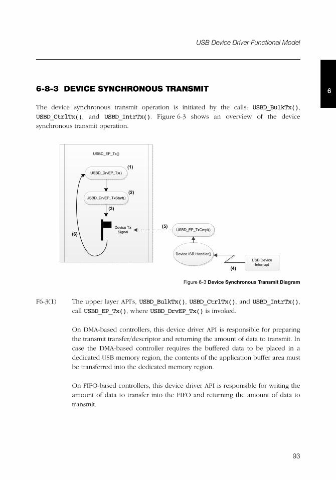
93
USB Device Driver Functional Model
66-8-3 DEVICE SYNCHRONOUS TRANSMIT
The device synchronous transmit operation is initiated by the calls: USBD_BulkTx(),
USBD_CtrlTx(), and USBD_IntrTx(). Figure 6-3 shows an overview of the device
synchronous transmit operation.
Figure 6-3 Device Synchronous Transmit Diagram
F6-3(1) The upper layer API’s, USBD_BulkTx(), USBD_CtrlTx(), and USBD_IntrTx(),
call USBD_EP_Tx(), where USBD_DrvEP_Tx() is invoked.
On DMA-based controllers, this device driver API is responsible for preparing
the transmit transfer/descriptor and returning the amount of data to transmit. In
case the DMA-based controller requires the buffered data to be placed in a
dedicated USB memory region, the contents of the application buffer area must
be transferred into the dedicated memory region.
On FIFO-based controllers, this device driver API is responsible for writing the
amount of data to transfer into the FIFO and returning the amount of data to
transmit.
�������� ��
������ ���� ��
������� �������
���
���
���
��������������� ���
���������������� ��
�������� ������
��
���
������ ���� ��� ���
���
94
Chapter 6
6 F6-3(2) The USBD_DrvEP_TxStart() API starts the transmit process.
On DMA-based controllers, this device driver API is responsible for queuing the
DMA transmit descriptor and enabling DMA transmit complete ISR’s.
On FIFO-based controllers, this device driver API is responsible for enabling
transmit complete ISR’s.
F6-3(3) While data is being transmitted, the device synchronous transmit operation
waits on the device transmit signal.
F6-3(4) The USB device controller triggers an interrupt request when it is finished
transmitting the data. This invokes the USB device driver interrupt service
routine (ISR) handler, directly or indirectly, depending on the architecture.
F6-3(5) Inside the USB device driver ISR handler, the type of interrupt request is
determined as a transmit interrupt. USBD_EP_TxCmpl() is called to unblock the
device transmit signal.
On DMA-based controllers, the transmit transfer is de-queued from a list of
completed transfers.
F6-3(6) The device transmit operation iterates through the process until the amount of
data transmitted matches the requested amount.
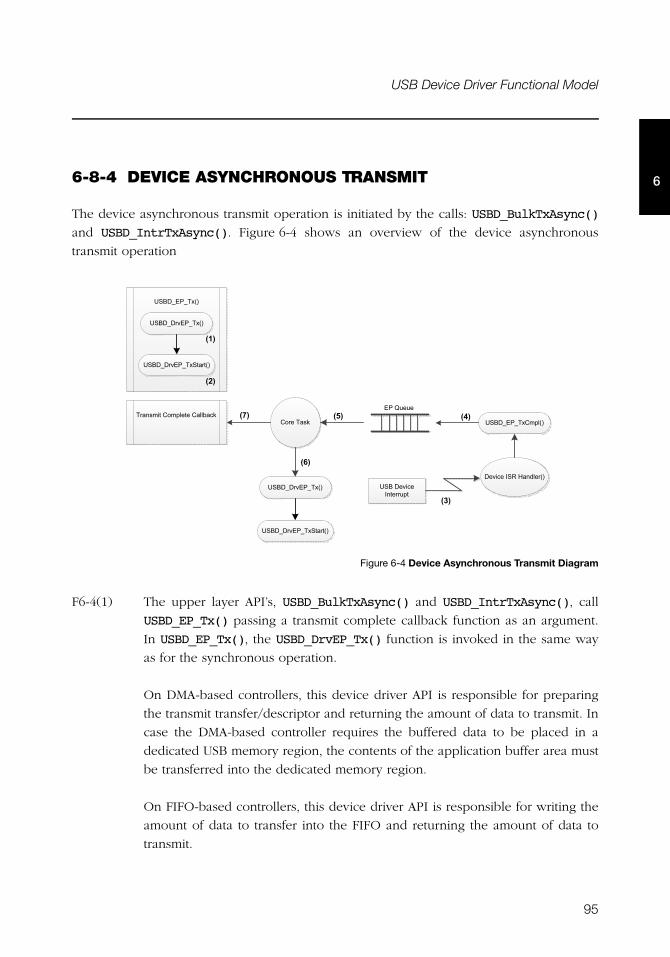
95
USB Device Driver Functional Model
66-8-4 DEVICE ASYNCHRONOUS TRANSMIT
The device asynchronous transmit operation is initiated by the calls: USBD_BulkTxAsync()
and USBD_IntrTxAsync(). Figure 6-4 shows an overview of the device asynchronous
transmit operation
.
Figure 6-4 Device Asynchronous Transmit Diagram
F6-4(1) The upper layer API’s, USBD_BulkTxAsync() and USBD_IntrTxAsync(), call
USBD_EP_Tx() passing a transmit complete callback function as an argument.
In USBD_EP_Tx(), the USBD_DrvEP_Tx() function is invoked in the same way
as for the synchronous operation.
On DMA-based controllers, this device driver API is responsible for preparing
the transmit transfer/descriptor and returning the amount of data to transmit. In
case the DMA-based controller requires the buffered data to be placed in a
dedicated USB memory region, the contents of the application buffer area must
be transferred into the dedicated memory region.
On FIFO-based controllers, this device driver API is responsible for writing the
amount of data to transfer into the FIFO and returning the amount of data to
transmit.
�������� ��
������ ���� ��
���
��������������� ���
���������������� ��
�������� ������
���
���� �� �!"
������ ���� ��
��!�����������������#��" �����
���
���$����
���
������ ���� ��� ���
������ ���� ��� ���
96
Chapter 6
6 F6-4(2) The USBD_DrvEP_TxStart() API starts the transmit process.
On DMA-based controllers, this device driver API is responsible for queuing the
DMA transmit descriptor and enabling DMA transmit complete ISR’s.
On FIFO-based controllers, this device driver API is responsible for enabling
transmit complete ISR’s.
The call to USBD_EP_Tx() returns immediately to the application (without
blocking) while data is being transmitted.
F6-4(3) The USB device controller triggers an interrupt request when it is finished
transmitting the data. This invokes the USB device driver interrupt service
routine (ISR) handler, directly or indirectly, depending on the architecture.
F6-4(4) Inside the USB device driver ISR handler, the type of interrupt request is
determined as a transmit interrupt. USBD_EP_TxCmpl() is called to queue the
endpoint that had its transfer completed.
On DMA-based controllers, the transmit transfer is de-queued from the list of
completed transfers.
F6-4(5) The core task de-queues the endpoint that completed a transfer.
F6-4(6) If the overall amount of data transmitted is less than the amount requested,
USBD_DrvEP_Tx() and USBD_DrvEP_TxStart() are called to transmit the
remaining amount of data.
F6-4(7) The device transmit operation finishes when the amount of data transmitted
matches the amount requested. The transmit complete callback is invoked to
notify the application about the completion of the process.
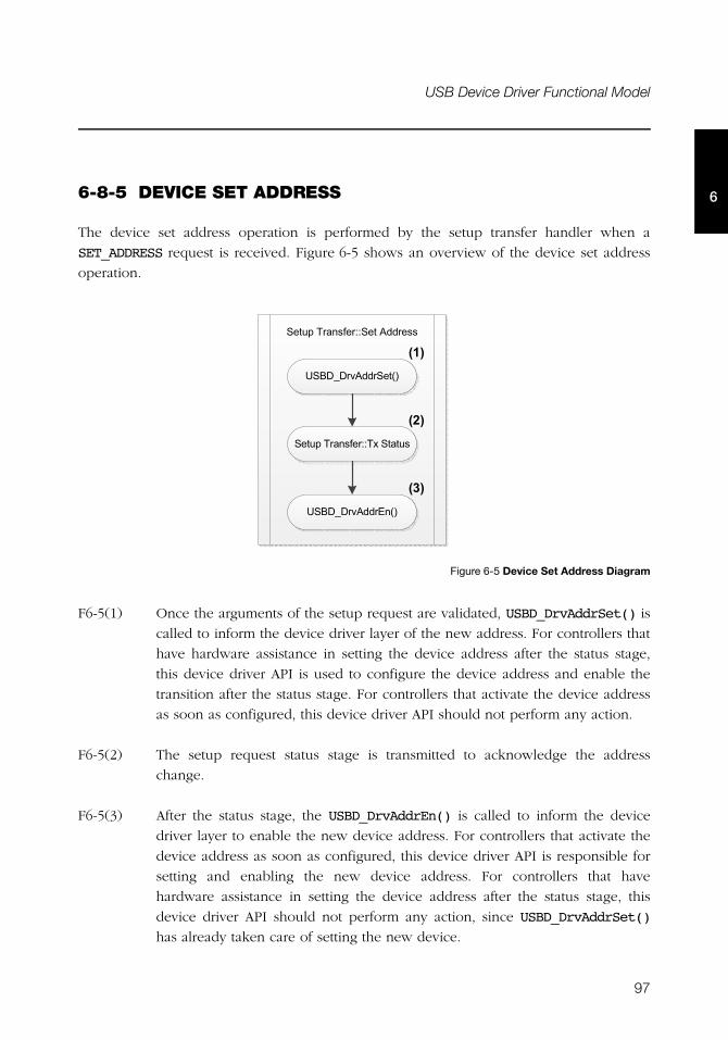
97
USB Device Driver Functional Model
66-8-5 DEVICE SET ADDRESS
The device set address operation is performed by the setup transfer handler when a
SET_ADDRESS request is received. Figure 6-5 shows an overview of the device set address
operation.
Figure 6-5 Device Set Address Diagram
F6-5(1) Once the arguments of the setup request are validated, USBD_DrvAddrSet() is
called to inform the device driver layer of the new address. For controllers that
have hardware assistance in setting the device address after the status stage,
this device driver API is used to configure the device address and enable the
transition after the status stage. For controllers that activate the device address
as soon as configured, this device driver API should not perform any action.
F6-5(2) The setup request status stage is transmitted to acknowledge the address
change.
F6-5(3) After the status stage, the USBD_DrvAddrEn() is called to inform the device
driver layer to enable the new device address. For controllers that activate the
device address as soon as configured, this device driver API is responsible for
setting and enabling the new device address. For controllers that have
hardware assistance in setting the device address after the status stage, this
device driver API should not perform any action, since USBD_DrvAddrSet()
has already taken care of setting the new device.
������ ��!%� &&����'�� �!!
������ �'�� �����
���
������ ��!%� && ������!
������ �'�� ����
���
���

98
Chapter 6
6
99
Chapter
7USB Classes
The USB classes available for the μC/USB-Device stack have some common characteristics.
This chapter explains these characteristics and the interactions with the core layer allowing
you to better understand the operation of classes.
7-1 CLASS INSTANCE CONCEPT
The USB classes available with the μC/USB-Device stack implement the concept of class
instances. A class instance represents one function within a device. The function can be
described by one interface or by a group of interfaces and belongs to a certain class.
Each USB class implementation has some configuration and functions in common based on
the concept of class instance. The common configuration and functions are presented in
Table 7-1. In the column heading 'Constants or Function', XXXX below can be replaced by
the name of the class: CDC, HID, MSC, PHDC or VENDOR (Vendor for function names). .
Table 7-1 Constants and Functions Related to the Concept of Multiple Class Instances
In terms of code implementation, the class will declare a local global table that contains a
class control structure. The size of the table is determined by the constant
USBD_XXXX_CFG_MAX_NBR_DEV. This class control structure is associated with one class
Constant or function Description
USBD_XXXX_CFG_MAX_NBR_DEV Configures the maximum number of class instances.
USBD_XXXX_CFG_MAX_NBR_CFG Configures the maximum number of configurations per device. During the class
initialization, a created class instance will be added to one or more
configurations.
USBD_XXXX_Add() Creates a new class instance.
USBD_XXXX_CfgAdd() Adds an existing class instance to the specified device configuration.
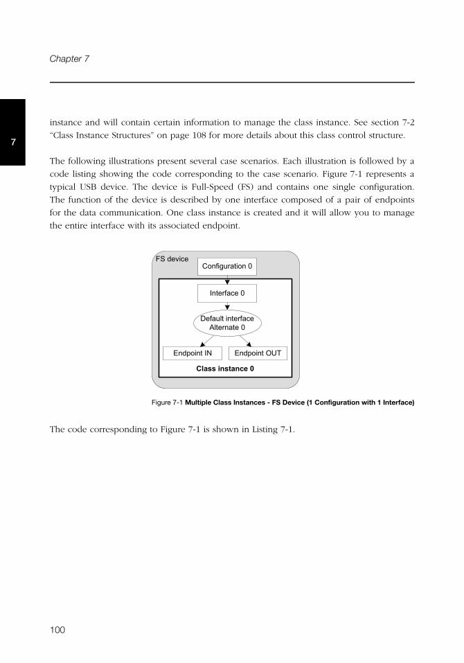
100
Chapter 7
7
instance and will contain certain information to manage the class instance. See section 7-2
“Class Instance Structures” on page 108 for more details about this class control structure.
The following illustrations present several case scenarios. Each illustration is followed by a
code listing showing the code corresponding to the case scenario. Figure 7-1 represents a
typical USB device. The device is Full-Speed (FS) and contains one single configuration.
The function of the device is described by one interface composed of a pair of endpoints
for the data communication. One class instance is created and it will allow you to manage
the entire interface with its associated endpoint.
Figure 7-1 Multiple Class Instances - FS Device (1 Configuration with 1 Interface)
The code corresponding to Figure 7-1 is shown in Listing 7-1.
(��������
�� ������� �����
���%��� ������)
���� %����)
��%��������� %���'��� �����)
����������* ���������+�

101
Class Instance Concept
7
Listing 7-1 Multiple Class Instances - FS Device (1 Configuration with 1 Interface) - Code
L7-1(1) Initialize the class. Any internal variables, structures, and class Real-Time
Operating System (RTOS) port will be initialized.
L7-1(2) Create the class instance, class_0. The function USBD_XXXX_Add() allocates a
class control structure associated to class_0. Depending on the class, besides
the parameter for an error code, USBD_XXXX_Add() may have additional
parameters representing class-specific information stored in the class control
structure.
L7-1(3) Add the class instance, class_0, to the specified configuration number, cfg_0.
USBD_XXXX_CfgAdd() will create the interface 0 and its associated endpoints
IN and OUT. Hence, the class instance encompasses the interface 0 and its
endpoints. Any communication done on the interface 0 will use the class
instance number, class_0.
Figure 7-2 represents an example of a high-speed capable device. The device can support
High-Speed (HS) and Full-Speed (FS). The device will contain two configurations: one valid
if the device operates at full-speed and another if it operates at high-speed. In each
configuration, interface 0 is the same but its associated endpoints are different. The
difference will be the endpoint maximum packet size which varies according to the speed.
USBD_ERR err;
CPU_INT08U class_0;
USBD_XXXX_Init(&err); (1)
if (err != USBD_ERR_NONE) {
/* $$$$ Handle the error. */
}
class_0 = USBD_XXXX_Add(&err); (2)
if (err != USBD_ERR_NONE) {
/* $$$$ Handle the error. */
}
USBD_XXXX_CfgAdd(class_0, dev_nbr, cfg_0, &err); (3)
if (err != USBD_ERR_NONE) {
/* $$$$ Handle the error. */
}
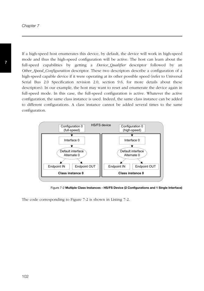
102
Chapter 7
7
If a high-speed host enumerates this device, by default, the device will work in high-speed
mode and thus the high-speed configuration will be active. The host can learn about the
full-speed capabilities by getting a Device_Qualifier descriptor followed by an
Other_Speed_Configuration descriptor. These two descriptors describe a configuration of a
high-speed capable device if it were operating at its other possible speed (refer to Universal
Serial Bus 2.0 Specification revision 2.0, section 9.6, for more details about these
descriptors). In our example, the host may want to reset and enumerate the device again in
full-speed mode. In this case, the full-speed configuration is active. Whatever the active
configuration, the same class instance is used. Indeed, the same class instance can be added
to different configurations. A class instance cannot be added several times to the same
configuration.
Figure 7-2 Multiple Class Instances - HS/FS Device (2 Configurations and 1 Single Interface)
The code corresponding to Figure 7-2 is shown in Listing 7-2.
��,(��������
�� ������� �����
���%��� ������)�%���-!�����
���� %����)
��%��������� %���'��� �����)
����������* ���������+�
�� ������� �����
���%��� ������)�.��.-!�����
���� %����)
��%��������� %���'��� �����)
����������* ���������+�
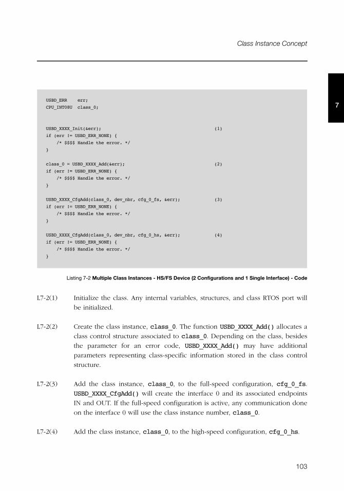
103
Class Instance Concept
7
Listing 7-2 Multiple Class Instances - HS/FS Device (2 Configurations and 1 Single Interface) - Code
L7-2(1) Initialize the class. Any internal variables, structures, and class RTOS port will
be initialized.
L7-2(2) Create the class instance, class_0. The function USBD_XXXX_Add() allocates a
class control structure associated to class_0. Depending on the class, besides
the parameter for an error code, USBD_XXXX_Add() may have additional
parameters representing class-specific information stored in the class control
structure.
L7-2(3) Add the class instance, class_0, to the full-speed configuration, cfg_0_fs.
USBD_XXXX_CfgAdd() will create the interface 0 and its associated endpoints
IN and OUT. If the full-speed configuration is active, any communication done
on the interface 0 will use the class instance number, class_0.
L7-2(4) Add the class instance, class_0, to the high-speed configuration, cfg_0_hs.
USBD_ERR err;
CPU_INT08U class_0;
USBD_XXXX_Init(&err); (1)
if (err != USBD_ERR_NONE) {
/* $$$$ Handle the error. */
}
class_0 = USBD_XXXX_Add(&err); (2)
if (err != USBD_ERR_NONE) {
/* $$$$ Handle the error. */
}
USBD_XXXX_CfgAdd(class_0, dev_nbr, cfg_0_fs, &err); (3)
if (err != USBD_ERR_NONE) {
/* $$$$ Handle the error. */
}
USBD_XXXX_CfgAdd(class_0, dev_nbr, cfg_0_hs, &err); (4)
if (err != USBD_ERR_NONE) {
/* $$$$ Handle the error. */
}
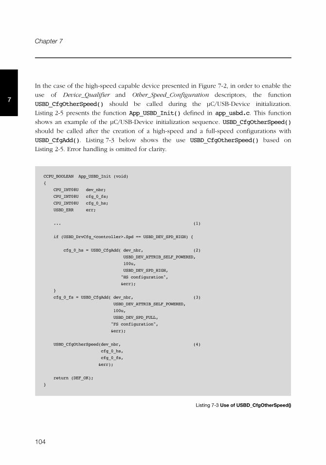
104
Chapter 7
7
In the case of the high-speed capable device presented in Figure 7-2, in order to enable the
use of Device_Qualifier and Other_Speed_Configuration descriptors, the function
USBD_CfgOtherSpeed() should be called during the μC/USB-Device initialization.
Listing 2-5 presents the function App_USBD_Init() defined in app_usbd.c. This function
shows an example of the μC/USB-Device initialization sequence. USBD_CfgOtherSpeed()
should be called after the creation of a high-speed and a full-speed configurations with
USBD_CfgAdd(). Listing 7-3 below shows the use USBD_CfgOtherSpeed() based on
Listing 2-5. Error handling is omitted for clarity.
Listing 7-3 Use of USBD_CfgOtherSpeed()
CCPU_BOOLEAN App_USBD_Init (void)
{
CPU_INT08U dev_nbr;
CPU_INT08U cfg_0_fs;
CPU_INT08U cfg_0_hs;
USBD_ERR err;
... (1)
if (USBD_DrvCfg_<controller>.Spd == USBD_DEV_SPD_HIGH) {
cfg_0_hs = USBD_CfgAdd( dev_nbr, (2)
USBD_DEV_ATTRIB_SELF_POWERED,
100u,
USBD_DEV_SPD_HIGH,
"HS configuration",
&err);
}
cfg_0_fs = USBD_CfgAdd( dev_nbr, (3)
USBD_DEV_ATTRIB_SELF_POWERED,
100u,
USBD_DEV_SPD_FULL,
"FS configuration",
&err);
USBD_CfgOtherSpeed(dev_nbr, (4)
cfg_0_hs,
cfg_0_fs,
&err);
return (DEF_OK);
}
105
Class Instance Concept
7
L7-3(1) Refer to Listing 2-5 for the beginning of the initialization.
L7-3(2) Create the high-speed configuration, cfg_0_hs, to your high-speed capable
device.
L7-3(3) Create the full-speed configuration, cfg_0_fs, to your high-speed capable
device.
L7-3(4) Associate the high-speed configuration cfg_0_hs with its other-speed
counterpart, cfg_0_fs.
Figure 7-3 represents a more complex example. A full-speed device is composed of two
configurations. The device has two functions which belong to the same class. Each function
is described by two interfaces. Each interface has a pair of bidirectional endpoints. In this
example, two class instances are created. Each class instance is associated with a group of
interfaces as opposed to Figure 7-1 and Figure 7-2 where the class instance was associated
to a single interface.
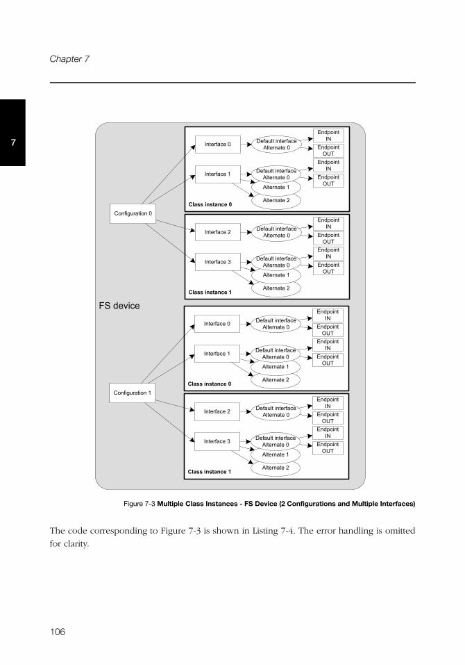
106
Chapter 7
7
Figure 7-3 Multiple Class Instances - FS Device (2 Configurations and Multiple Interfaces)
The code corresponding to Figure 7-3 is shown in Listing 7-4. The error handling is omitted
for clarity.
(��������
�� ������� �����'��� �����/
'��� �����0
���%��� ������)
���� %����) ��%��������� %���'��� �����)
����������*
���������+�
���� %����0 ��%��������� %���'��� �����)
����������*
���������+�
�� ������� �����'��� �����/
'��� �����0
���� %����/ ��%��������� %���'��� �����)
����������*
���������+�
���� %����1 ��%��������� %���'��� �����)
����������*
���������+�
�� ������� �����'��� �����/
'��� �����0
���%��� ������0
���� %����) ��%��������� %���'��� �����)
����������*
���������+�
���� %����0 ��%��������� %���'��� �����)
����������*
���������+�
�� ������� �����'��� �����/
'��� �����0
���� %����/ ��%��������� %���'��� �����)
����������*
���������+�
���� %����1 ��%��������� %���'��� �����)
����������*
���������+�
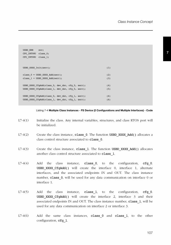
107
Class Instance Concept
7
Listing 7-4 Multiple Class Instances - FS Device (2 Configurations and Multiple Interfaces) - Code
L7-4(1) Initialize the class. Any internal variables, structures, and class RTOS port will
be initialized.
L7-4(2) Create the class instance, class_0. The function USBD_XXXX_Add() allocates a
class control structure associated to class_0.
L7-4(3) Create the class instance, class_1. The function USBD_XXXX_Add() allocates
another class control structure associated to class_1.
L7-4(4) Add the class instance, class_0, to the configuration, cfg_0.
USBD_XXXX_CfgAdd() will create the interface 0, interface 1, alternate
interfaces, and the associated endpoints IN and OUT. The class instance
number, class_0, will be used for any data communication on interface 0 or
interface 1.
L7-4(5) Add the class instance, class_1, to the configuration, cfg_0.
USBD_XXXX_CfgAdd() will create the interface 2, interface 3 and their
associated endpoints IN and OUT. The class instance number, class_1, will be
used for any data communication on interface 2 or interface 3.
L7-4(6) Add the same class instances, class_0 and class_1, to the other
configuration, cfg_1.
USBD_ERR err;
CPU_INT08U class_0;
CPU_INT08U class_1;
USBD_XXXX_Init(&err); (1)
class_0 = USBD_XXXX_Add(&err); (2)
class_1 = USBD_XXXX_Add(&err); (3)
USBD_XXXX_CfgAdd(class_0, dev_nbr, cfg_0, &err); (4)
USBD_XXXX_CfgAdd(class_1, dev_nbr, cfg_0, &err); (5)
USBD_XXXX_CfgAdd(class_0, dev_nbr, cfg_1, &err); (6)
USBD_XXXX_CfgAdd(class_1, dev_nbr, cfg_1, &err); (6)
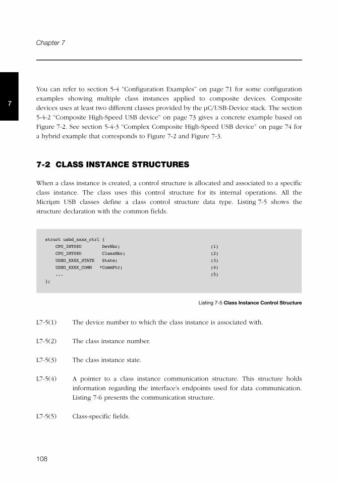
108
Chapter 7
7
You can refer to section 5-4 “Configuration Examples” on page 71 for some configuration
examples showing multiple class instances applied to composite devices. Composite
devices uses at least two different classes provided by the μC/USB-Device stack. The section
5-4-2 “Composite High-Speed USB device” on page 73 gives a concrete example based on
Figure 7-2. See section 5-4-3 “Complex Composite High-Speed USB device” on page 74 for
a hybrid example that corresponds to Figure 7-2 and Figure 7-3.
7-2 CLASS INSTANCE STRUCTURES
When a class instance is created, a control structure is allocated and associated to a specific
class instance. The class uses this control structure for its internal operations. All the
Micriμm USB classes define a class control structure data type. Listing 7-5 shows the
structure declaration with the common fields.
Listing 7-5 Class Instance Control Structure
L7-5(1) The device number to which the class instance is associated with.
L7-5(2) The class instance number.
L7-5(3) The class instance state.
L7-5(4) A pointer to a class instance communication structure. This structure holds
information regarding the interface’s endpoints used for data communication.
Listing 7-6 presents the communication structure.
L7-5(5) Class-specific fields.
struct usbd_xxxx_ctrl {
CPU_INT08U DevNbr; (1)
CPU_INT08U ClassNbr; (2)
USBD_XXXX_STATE State; (3)
USBD_XXXX_COMM *CommPtr; (4)
... (5)
};
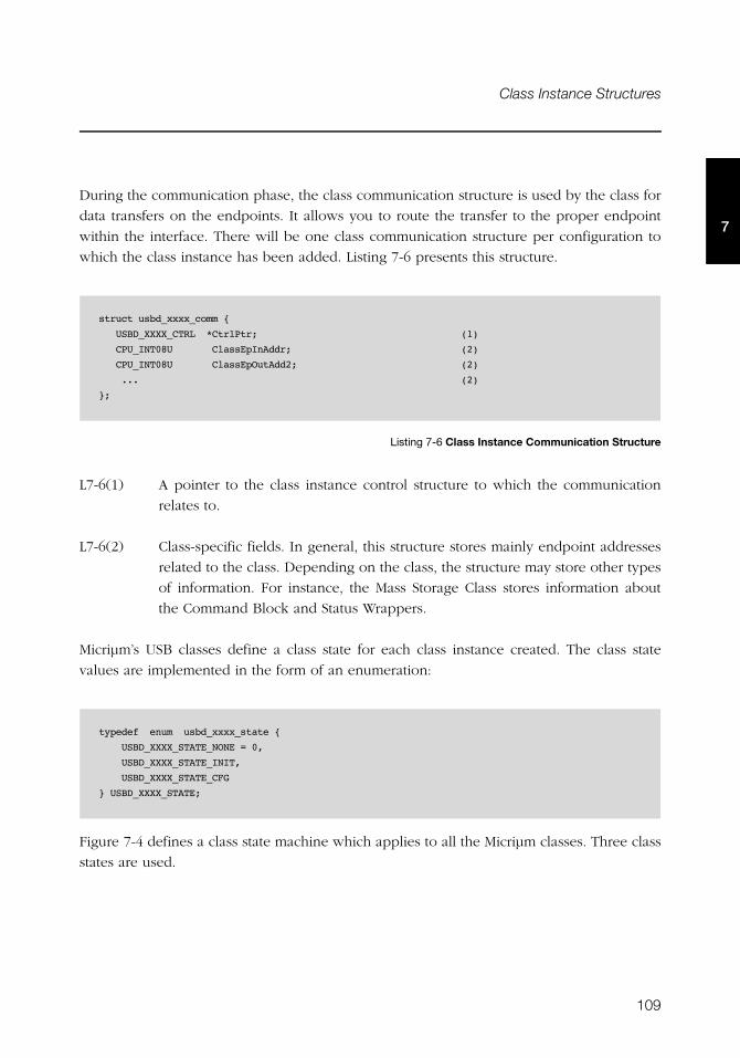
109
Class Instance Structures
7
During the communication phase, the class communication structure is used by the class for
data transfers on the endpoints. It allows you to route the transfer to the proper endpoint
within the interface. There will be one class communication structure per configuration to
which the class instance has been added. Listing 7-6 presents this structure.
Listing 7-6 Class Instance Communication Structure
L7-6(1) A pointer to the class instance control structure to which the communication
relates to.
L7-6(2) Class-specific fields. In general, this structure stores mainly endpoint addresses
related to the class. Depending on the class, the structure may store other types
of information. For instance, the Mass Storage Class stores information about
the Command Block and Status Wrappers.
Micriμm’s USB classes define a class state for each class instance created. The class state
values are implemented in the form of an enumeration:
Figure 7-4 defines a class state machine which applies to all the Micriμm classes. Three class
states are used.
struct usbd_xxxx_comm {
USBD_XXXX_CTRL *CtrlPtr; (1)
CPU_INT08U ClassEpInAddr; (2)
CPU_INT08U ClassEpOutAdd2; (2)
... (2)
};
typedef enum usbd_xxxx_state {
USBD_XXXX_STATE_NONE = 0,
USBD_XXXX_STATE_INIT,
USBD_XXXX_STATE_CFG
} USBD_XXXX_STATE;
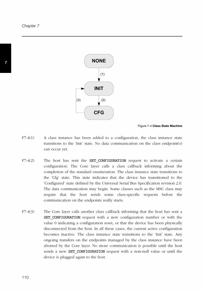
110
Chapter 7
7
Figure 7-4 Class State Machine
F7-4(1) A class instance has been added to a configuration, the class instance state
transitions to the ‘Init’ state. No data communication on the class endpoint(s)
can occur yet.
F7-4(2) The host has sent the SET_CONFIGURATION request to activate a certain
configuration. The Core layer calls a class callback informing about the
completion of the standard enumeration. The class instance state transitions to
the ‘Cfg’ state. This state indicates that the device has transitioned to the
‘Configured’ state defined by the Universal Serial Bus Specification revision 2.0.
The data communication may begin. Some classes such as the MSC class may
require that the host sends some class-specific requests before the
communication on the endpoints really starts.
F7-4(3) The Core layer calls another class callback informing that the host has sent a
SET_CONFIGURATION request with a new configuration number or with the
value 0 indicating a configuration reset, or that the device has been physically
disconnected from the host. In all these cases, the current active configuration
becomes inactive. The class instance state transitions to the ‘Init’ state. Any
ongoing transfers on the endpoints managed by the class instance have been
aborted by the Core layer. No more communication is possible until the host
sends a new SET_CONFIGURATION request with a non-null value or until the
device is plugged again to the host.
����
����
���
�0�
�/��1�
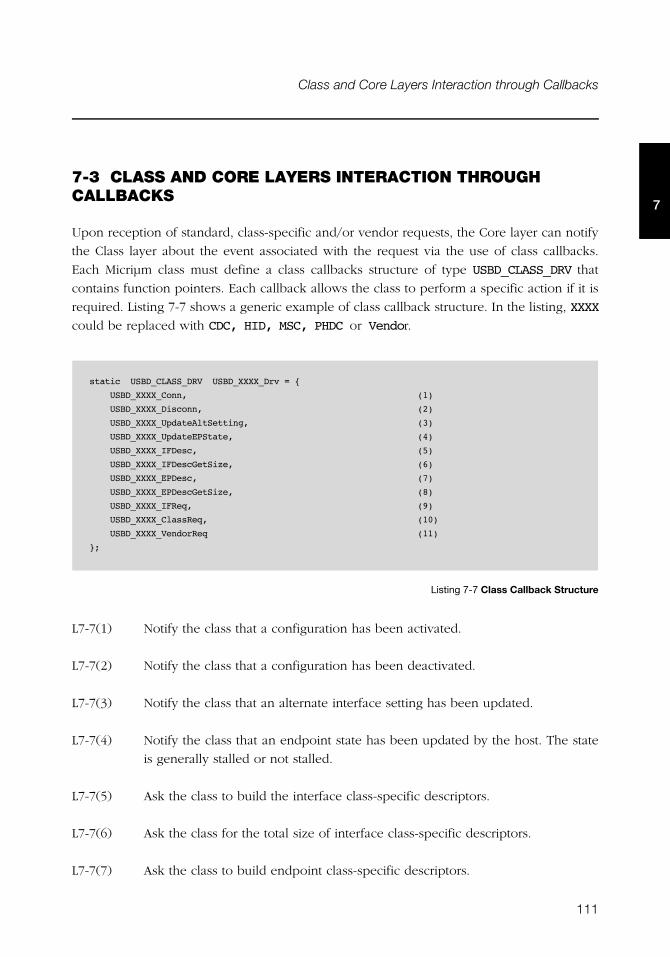
111
Class and Core Layers Interaction through Callbacks
7
7-3 CLASS AND CORE LAYERS INTERACTION THROUGH CALLBACKS
Upon reception of standard, class-specific and/or vendor requests, the Core layer can notify
the Class layer about the event associated with the request via the use of class callbacks.
Each Micriμm class must define a class callbacks structure of type USBD_CLASS_DRV that
contains function pointers. Each callback allows the class to perform a specific action if it is
required. Listing 7-7 shows a generic example of class callback structure. In the listing, XXXX
could be replaced with CDC, HID, MSC, PHDC or Vendor.
Listing 7-7 Class Callback Structure
L7-7(1) Notify the class that a configuration has been activated.
L7-7(2) Notify the class that a configuration has been deactivated.
L7-7(3) Notify the class that an alternate interface setting has been updated.
L7-7(4) Notify the class that an endpoint state has been updated by the host. The state
is generally stalled or not stalled.
L7-7(5) Ask the class to build the interface class-specific descriptors.
L7-7(6) Ask the class for the total size of interface class-specific descriptors.
L7-7(7) Ask the class to build endpoint class-specific descriptors.
static USBD_CLASS_DRV USBD_XXXX_Drv = {
USBD_XXXX_Conn, (1)
USBD_XXXX_Disconn, (2)
USBD_XXXX_UpdateAltSetting, (3)
USBD_XXXX_UpdateEPState, (4)
USBD_XXXX_IFDesc, (5)
USBD_XXXX_IFDescGetSize, (6)
USBD_XXXX_EPDesc, (7)
USBD_XXXX_EPDescGetSize, (8)
USBD_XXXX_IFReq, (9)
USBD_XXXX_ClassReq, (10)
USBD_XXXX_VendorReq (11)
};
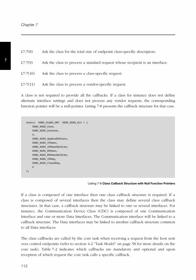
112
Chapter 7
7
L7-7(8) Ask the class for the total size of endpoint class-specific descriptors.
L7-7(9) Ask the class to process a standard request whose recipient is an interface.
L7-7(10) Ask the class to process a class-specific request.
L7-7(11) Ask the class to process a vendor-specific request.
A class is not required to provide all the callbacks. If a class for instance does not define
alternate interface settings and does not process any vendor requests, the corresponding
function pointer will be a null-pointer. Listing 7-8 presents the callback structure for that case.
Listing 7-8 Class Callback Structure with Null Function Pointers
If a class is composed of one interface then one class callback structure is required. If a
class is composed of several interfaces then the class may define several class callback
structures. In that case, a callback structure may be linked to one or several interfaces. For
instance, the Communication Device Class (CDC) is composed of one Communication
Interface and one or more Data Interfaces. The Communication interface will be linked to a
callback structure. The Data interfaces may be linked to another callback structure common
to all Data interfaces.
The class callbacks are called by the core task when receiving a request from the host sent
over control endpoints (refer to section 4-2 “Task Model” on page 58 for more details on the
core task). Table 7-2 indicates which callbacks are mandatory and optional and upon
reception of which request the core task calls a specific callback.
static USBD_CLASS_DRV USBD_XXXX_Drv = {
USBD_XXXX_Conn,
USBD_XXXX_Disconn,
0,
USBD_XXXX_UpdateEPState,
USBD_XXXX_IFDesc,
USBD_XXXX_IFDescGetSize,
USBD_XXXX_EPDesc,
USBD_XXXX_EPDescGetSize,
USBD_XXXX_IFReq,
USBD_XXXX_ClassReq,
0
};
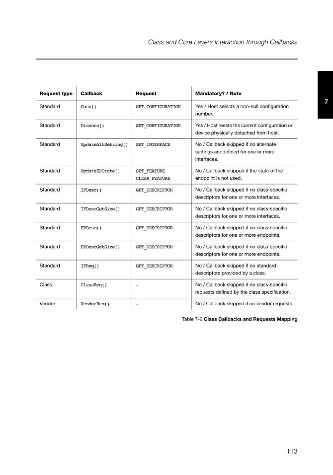
113
Class and Core Layers Interaction through Callbacks
7
Table 7-2 Class Callbacks and Requests Mapping
Request type Callback Request Mandatory? / Note
Standard Conn() SET_CONFIGURATION Yes / Host selects a non-null configuration
number.
Standard Disconn() SET_CONFIGURATION Yes / Host resets the current configuration or
device physically detached from host.
Standard UpdateAltSetting() SET_INTERFACE No / Callback skipped if no alternate
settings are defined for one or more
interfaces.
Standard UpdateEPState() SET_FEATURE
CLEAR_FEATURE
No / Callback skipped if the state of the
endpoint is not used.
Standard IFDesc() GET_DESCRIPTOR No / Callback skipped if no class-specific
descriptors for one or more interfaces.
Standard IFDescGetSize() GET_DESCRIPTOR No / Callback skipped if no class-specific
descriptors for one or more interfaces.
Standard EPDesc() GET_DESCRIPTOR No / Callback skipped if no class-specific
descriptors for one or more endpoints.
Standard EPDescGetSize() GET_DESCRIPTOR No / Callback skipped if no class-specific
descriptors for one or more endpoints.
Standard IFReq() GET_DESCRIPTOR No / Callback skipped if no standard
descriptors provided by a class.
Class ClassReq() - No / Callback skipped if no class-specific
requests defined by the class specification.
Vendor VendorReq() - No / Callback skipped if no vendor requests.

114
Chapter 7
7
115
Chapter
8Communications Device Class
This chapter describes the Communications Device Class (CDC) class and the associated
CDC subclass supported by μC/USB-Device. μC/USB-Device currently supports the Abstract
Control Model (ACM) subclass, which is especially used for serial emulation.
The CDC and the associated subclass implementation complies with the following
specifications:
■ Universal Serial Bus, Class Definitions for Communications Devices, Revision 1.2,
November 3 2010.
■ Universal Serial Bus, Communications, Subclass for PSTN Devices, revision 1.2,
February 9, 2007.
CDC includes various telecommunication and networking devices. Telecommunication
devices encompass analog modems, analog and digital telephones, ISDN terminal adapters,
etc. Networking devices contain, for example, ADSL and cable modems, Ethernet adapters
and hubs. CDC defines a framework to encapsulate existing communication services
standards, such as V.250 (for modems over telephone network) and Ethernet (for local area
network devices), using a USB link. A communication device is in charge of device
management, call management when needed and data transmission. CDC defines seven
major groups of devices. Each group belongs to a model of communication which may
include several subclasses. Each group of devices has its own specification besides the CDC
base class. The seven groups are:
■ Public Switched Telephone Network (PSTN), devices including voiceband modems,
telephones and serial emulation devices.
■ Integrated Services Digital Network (ISDN) devices, including terminal adaptors and
telephones.
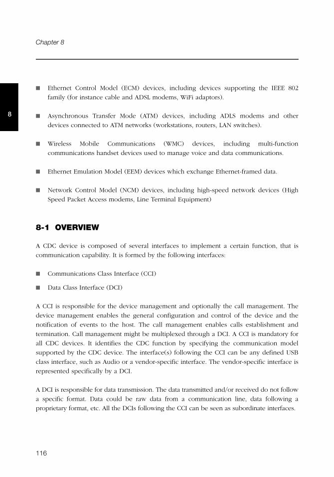
116
Chapter 8
8
■ Ethernet Control Model (ECM) devices, including devices supporting the IEEE 802
family (for instance cable and ADSL modems, WiFi adaptors).
■ Asynchronous Transfer Mode (ATM) devices, including ADLS modems and other
devices connected to ATM networks (workstations, routers, LAN switches).
■ Wireless Mobile Communications (WMC) devices, including multi-function
communications handset devices used to manage voice and data communications.
■ Ethernet Emulation Model (EEM) devices which exchange Ethernet-framed data.
■ Network Control Model (NCM) devices, including high-speed network devices (High
Speed Packet Access modems, Line Terminal Equipment)
8-1 OVERVIEW
A CDC device is composed of several interfaces to implement a certain function, that is
communication capability. It is formed by the following interfaces:
■ Communications Class Interface (CCI)
■ Data Class Interface (DCI)
A CCI is responsible for the device management and optionally the call management. The
device management enables the general configuration and control of the device and the
notification of events to the host. The call management enables calls establishment and
termination. Call management might be multiplexed through a DCI. A CCI is mandatory for
all CDC devices. It identifies the CDC function by specifying the communication model
supported by the CDC device. The interface(s) following the CCI can be any defined USB
class interface, such as Audio or a vendor-specific interface. The vendor-specific interface is
represented specifically by a DCI.
A DCI is responsible for data transmission. The data transmitted and/or received do not follow
a specific format. Data could be raw data from a communication line, data following a
proprietary format, etc. All the DCIs following the CCI can be seen as subordinate interfaces.
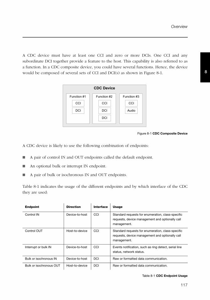
117
Overview
8
A CDC device must have at least one CCI and zero or more DCIs. One CCI and any
subordinate DCI together provide a feature to the host. This capability is also referred to as
a function. In a CDC composite device, you could have several functions. Hence, the device
would be composed of several sets of CCI and DCI(s) as shown in Figure 8-1.
Figure 8-1 CDC Composite Device
A CDC device is likely to use the following combination of endpoints:
■ A pair of control IN and OUT endpoints called the default endpoint.
■ An optional bulk or interrupt IN endpoint.
■ A pair of bulk or isochronous IN and OUT endpoints.
Table 8-1 indicates the usage of the different endpoints and by which interface of the CDC
they are used:
Table 8-1 CDC Endpoint Usage
Endpoint Direction Interface Usage
Control IN Device-to-host CCI Standard requests for enumeration, class-specific
requests, device management and optionally call
management.
Control OUT Host-to-device CCI Standard requests for enumeration, class-specific
requests, device management and optionally call
management.
Interrupt or bulk IN Device-to-host CCI Events notification, such as ring detect, serial line
status, network status.
Bulk or isochronous IN Device-to-host DCI Raw or formatted data communication.
Bulk or isochronous OUT Host-to-device DCI Raw or formatted data communication.
����������
(��������2/
���
���
���
(��������20
���
���
(��������21
���
'����
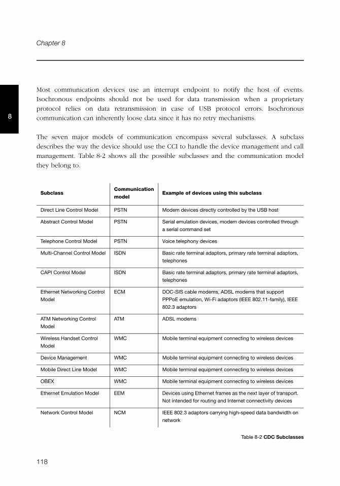
118
Chapter 8
8
Most communication devices use an interrupt endpoint to notify the host of events.
Isochronous endpoints should not be used for data transmission when a proprietary
protocol relies on data retransmission in case of USB protocol errors. Isochronous
communication can inherently loose data since it has no retry mechanisms.
The seven major models of communication encompass several subclasses. A subclass
describes the way the device should use the CCI to handle the device management and call
management. Table 8-2 shows all the possible subclasses and the communication model
they belong to.
Table 8-2 CDC Subclasses
SubclassCommunication
modelExample of devices using this subclass
Direct Line Control Model PSTN Modem devices directly controlled by the USB host
Abstract Control Model PSTN Serial emulation devices, modem devices controlled through
a serial command set
Telephone Control Model PSTN Voice telephony devices
Multi-Channel Control Model ISDN Basic rate terminal adaptors, primary rate terminal adaptors,
telephones
CAPI Control Model ISDN Basic rate terminal adaptors, primary rate terminal adaptors,
telephones
Ethernet Networking Control
Model
ECM DOC-SIS cable modems, ADSL modems that support
PPPoE emulation, Wi-Fi adaptors (IEEE 802.11-family), IEEE
802.3 adaptors
ATM Networking Control
Model
ATM ADSL modems
Wireless Handset Control
Model
WMC Mobile terminal equipment connecting to wireless devices
Device Management WMC Mobile terminal equipment connecting to wireless devices
Mobile Direct Line Model WMC Mobile terminal equipment connecting to wireless devices
OBEX WMC Mobile terminal equipment connecting to wireless devices
Ethernet Emulation Model EEM Devices using Ethernet frames as the next layer of transport.
Not intended for routing and Internet connectivity devices
Network Control Model NCM IEEE 802.3 adaptors carrying high-speed data bandwidth on
network
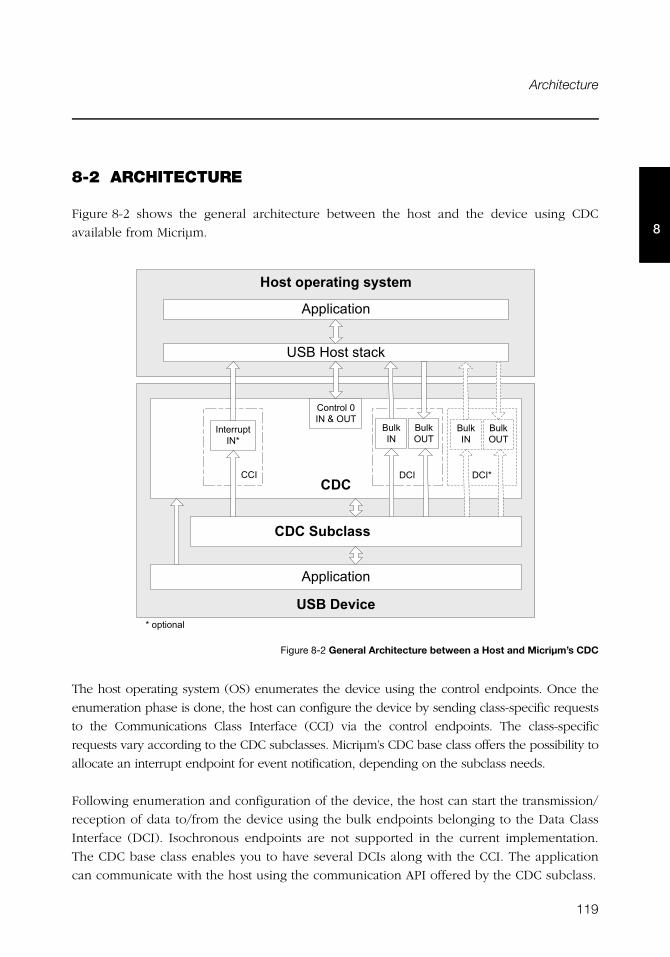
119
Architecture
8
8-2 ARCHITECTURE
Figure 8-2 shows the general architecture between the host and the device using CDC
available from Micriμm.
Figure 8-2 General Architecture between a Host and Micriμm’s CDC
The host operating system (OS) enumerates the device using the control endpoints. Once the
enumeration phase is done, the host can configure the device by sending class-specific requests
to the Communications Class Interface (CCI) via the control endpoints. The class-specific
requests vary according to the CDC subclasses. Micriμm’s CDC base class offers the possibility to
allocate an interrupt endpoint for event notification, depending on the subclass needs.
Following enumeration and configuration of the device, the host can start the transmission/
reception of data to/from the device using the bulk endpoints belonging to the Data Class
Interface (DCI). Isochronous endpoints are not supported in the current implementation.
The CDC base class enables you to have several DCIs along with the CCI. The application
can communicate with the host using the communication API offered by the CDC subclass.
� ��� !�" ���#��$���%
'����������
������!��!���"
&'(�������
���
���� ���)�*�3�+�
���� ����*4
���
���"��*
���"�+�
���4���
���"��*
���"�+�
����')*�� ��
'����������
4���������
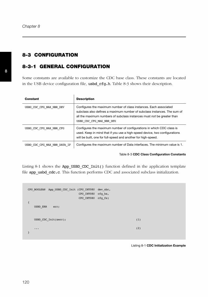
120
Chapter 8
8
8-3 CONFIGURATION
8-3-1 GENERAL CONFIGURATION
Some constants are available to customize the CDC base class. These constants are located
in the USB device configuration file, usbd_cfg.h. Table 8-3 shows their description.
Table 8-3 CDC Class Configuration Constants
Listing 8-1 shows the App_USBD_CDC_Init() function defined in the application template
file app_usbd_cdc.c. This function performs CDC and associated subclass initialization.
Listing 8-1 CDC Initialization Example
Constant Description
USBD_CDC_CFG_MAX_NBR_DEV Configures the maximum number of class instances. Each associated
subclass also defines a maximum number of subclass instances. The sum of
all the maximum numbers of subclass instances must not be greater than
USBD_CDC_CFG_MAX_NBR_DEV.
USBD_CDC_CFG_MAX_NBR_CFG Configures the maximum number of configurations in which CDC class is
used. Keep in mind that if you use a high-speed device, two configurations
will be built, one for full-speed and another for high-speed.
USBD_CDC_CFG_MAX_NBR_DATA_IF Configures the maximum number of Data interfaces. The minimum value is 1.
CPU_BOOLEAN App_USBD_CDC_Init (CPU_INT08U dev_nbr,
CPU_INT08U cfg_hs,
CPU_INT08U cfg_fs)
{
USBD_ERR err;
USBD_CDC_Init(&err); (1)
... (2)
}
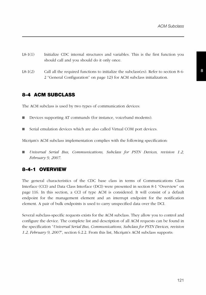
121
ACM Subclass
8
L8-1(1) Initialize CDC internal structures and variables. This is the first function you
should call and you should do it only once.
L8-1(2) Call all the required functions to initialize the subclass(es). Refer to section 8-4-
2 “General Configuration” on page 123 for ACM subclass initialization.
8-4 ACM SUBCLASS
The ACM subclass is used by two types of communication devices:
■ Devices supporting AT commands (for instance, voiceband modems).
■ Serial emulation devices which are also called Virtual COM port devices.
Micriμm’s ACM subclass implementation complies with the following specification:
■ Universal Serial Bus, Communications, Subclass for PSTN Devices, revision 1.2,
February 9, 2007.
8-4-1 OVERVIEW
The general characteristics of the CDC base class in terms of Communications Class
Interface (CCI) and Data Class Interface (DCI) were presented in section 8-1 “Overview” on
page 116. In this section, a CCI of type ACM is considered. It will consist of a default
endpoint for the management element and an interrupt endpoint for the notification
element. A pair of bulk endpoints is used to carry unspecified data over the DCI.
Several subclass-specific requests exists for the ACM subclass. They allow you to control and
configure the device. The complete list and description of all ACM requests can be found in
the specification “Universal Serial Bus, Communications, Subclass for PSTN Devices, revision
1.2, February 9, 2007”, section 6.2.2. From this list, Micriμm’s ACM subclass supports:
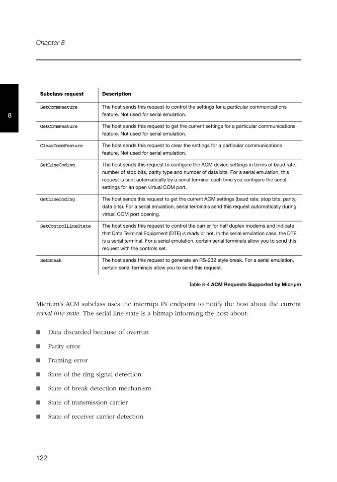
122
Chapter 8
8
Table 8-4 ACM Requests Supported by Micriμm
Micriμm’s ACM subclass uses the interrupt IN endpoint to notify the host about the current
serial line state. The serial line state is a bitmap informing the host about:
■ Data discarded because of overrun
■ Parity error
■ Framing error
■ State of the ring signal detection
■ State of break detection mechanism
■ State of transmission carrier
■ State of receiver carrier detection
Subclass request Description
SetCommFeature The host sends this request to control the settings for a particular communications
feature. Not used for serial emulation.
GetCommFeature The host sends this request to get the current settings for a particular communications
feature. Not used for serial emulation.
ClearCommFeature The host sends this request to clear the settings for a particular communications
feature. Not used for serial emulation.
SetLineCoding The host sends this request to configure the ACM device settings in terms of baud rate,
number of stop bits, parity type and number of data bits. For a serial emulation, this
request is sent automatically by a serial terminal each time you configure the serial
settings for an open virtual COM port.
GetLineCoding The host sends this request to get the current ACM settings (baud rate, stop bits, parity,
data bits). For a serial emulation, serial terminals send this request automatically during
virtual COM port opening.
SetControlLineState The host sends this request to control the carrier for half duplex modems and indicate
that Data Terminal Equipment (DTE) is ready or not. In the serial emulation case, the DTE
is a serial terminal. For a serial emulation, certain serial terminals allow you to send this
request with the controls set.
SetBreak The host sends this request to generate an RS-232 style break. For a serial emulation,
certain serial terminals allow you to send this request.
123
ACM Subclass
8
8-4-2 GENERAL CONFIGURATION
Table 8-5 shows the constant available to customize the ACM serial emulation subclass. This
constant is located in the USB device configuration file, usbd_cfg.h.
Table 8-5 ACM Serial Emulation Subclass Configuration Constants
8-4-3 SUBCLASS INSTANCE CONFIGURATION
Before starting the communication phase, your application needs to initialize and configure
the class to suit its needs. Table 8-6 summarizes the initialization functions provided by the
ACM subclass. For more details about the functions’ parameters, refer to section C-2 “CDC
ACM Subclass Functions” on page 369.
Table 8-6 ACM Subclass Initialization API Summary
Constant Description
USBD_ACM_SERIAL_CFG_MAX_NBR_DEV Configures the maximum number of subclass instances. The constant
value cannot be greater than USBD_CDC_CFG_MAX_NBR_DEV. Unless you
plan on having multiple configurations or interfaces using different
class instances, this can be set to 1.
Function name Operation
USBD_ACM_SerialInit() Initializes ACM subclass internal structures and variables.
USBD_ACM_SerialAdd() Creates a new instance of ACM subclass.
USBD_ACM_SerialCfgAdd() Adds an existing ACM instance to the specified device configuration.
USBD_ACM_SerialLineCodingReg() Registers line coding notification callback.
USBD_ACM_SerialLineCtrlReg() Registers line control notification callback.
124
Chapter 8
8
You need to call these functions in the order shown below to successfully initialize the ACM
subclass:
1 Call USBD_ACM_SerialInit()
This function initializes all internal structures and variables that the ACM subclass needs.
You should call this function only once even if you use multiple class instances.
2 Call USBD_ACM_SerialAdd()
This function allocates an ACM subclass instance. Internally, this function allocates a
CDC class instance. It also allows you to specify the line state notification interval
expressed in milliseconds.
3 Call USBD_ACM_SerialLineCodingReg()
This function allows you to register a callback used by the ACM subclass to notify the
application about a change in the serial line coding settings (that is baud rate, number
of stop bits, parity and number of data bits).
4 Call USBD_ACM_SerialLineCtrlReg()
This function allows you to register a callback used by the ACM subclass to notify the
application about a change in the serial line state (that is carrier control and a flag
indicating that data equipment terminal is present or not).
5 Call USBD_ACM_SerialCfgAdd()
Finally, once the ACM subclass instance has been created, you must add it to a specific
configuration.
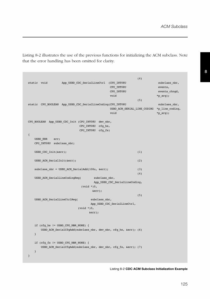
125
ACM Subclass
8
Listing 8-2 illustrates the use of the previous functions for initializing the ACM subclass. Note
that the error handling has been omitted for clarity.
Listing 8-2 CDC ACM Subclass Initialization Example
(4)
static void App_USBD_CDC_SerialLineCtrl (CPU_INT08U subclass_nbr,
CPU_INT08U events,
CPU_INT08U events_chngd,
void *p_arg);
(5)
static CPU_BOOLEAN App_USBD_CDC_SerialLineCoding(CPU_INT08U subclass_nbr,
USBD_ACM_SERIAL_LINE_CODING *p_line_coding,
void *p_arg);
CPU_BOOLEAN App_USBD_CDC_Init (CPU_INT08U dev_nbr,
CPU_INT08U cfg_hs,
CPU_INT08U cfg_fs)
{
USBD_ERR err;
CPU_INT08U subclass_nbr;
USBD_CDC_Init(&err); (1)
USBD_ACM_SerialInit(&err); (2)
subclass_nbr = USBD_ACM_SerialAdd(100u, &err); (3)
(4)
USBD_ACM_SerialLineCodingReg( subclass_nbr,
App_USBD_CDC_SerialLineCoding,
(void *)0,
&err);
(5)
USBD_ACM_SerialLineCtrlReg( subclass_nbr,
App_USBD_CDC_SerialLineCtrl,
(void *)0,
&err);
if (cfg_hs != USBD_CFG_NBR_NONE) {
USBD_ACM_SerialCfgAdd(subclass_nbr, dev_nbr, cfg_hs, &err); (6)
}
if (cfg_fs != USBD_CFG_NBR_NONE) {
USBD_ACM_SerialCfgAdd(subclass_nbr, dev_nbr, cfg_fs, &err); (7)
}
}
126
Chapter 8
8
L8-2(1) Initialize CDC internal structures and variables.
L8-2(2) Initialize CDC ACM internal structures and variables.
L8-2(3) Create a new CDC ACM subclass instance. In this example, the line state
notification interval is 100 ms. In the CCI, an interrupt IN endpoint is used to
asynchronously notify the host of the status of the different signals forming the
serial line. The line state notification interval corresponds to the interrupt
endpoint’s polling interval.
L8-2(4) Register the application callback, App_USBD_CDC_SerialLineCoding(). It is
called by the ACM subclass when the class-specific request SET_LINE_CODING
has been received by the device. This request allows the host to specify the
serial line settings (baud rate, stop bits, parity and data bits). Refer to “CDC
PSTN Subclass, revision 1.2”, section 6.3.10 for more details about this class-
specific request.
L8-2(5) Register the application callback, App_USBD_CDC_SerialLineCtrl(). It is
called by the ACM subclass when the class-specific request
SET_CONTROL_LINE_STATE has been received by the device. This request
generates RS-232/V.24 style control signals. Refer to “CDC PSTN Subclass,
revision 1.2”, section 6.3.12 for more details about this class-specific request.
L8-2(6) Check if the high-speed configuration is active and proceed to add the ACM
subclass instance to this configuration.
L8-2(7) Check if the full-speed configuration is active and proceed to add the ACM
subclass instance to this configuration.
Listing 8-2 also illustrates an example of multiple configurations. The functions
USBD_ACM_SerialAdd() and USBD_ACM_SerialCfgAdd() allow you to create multiple
configurations and multiple instances architecture. Refer to section 7-1 “Class Instance
Concept” on page 99 for more details about multiple class instances.
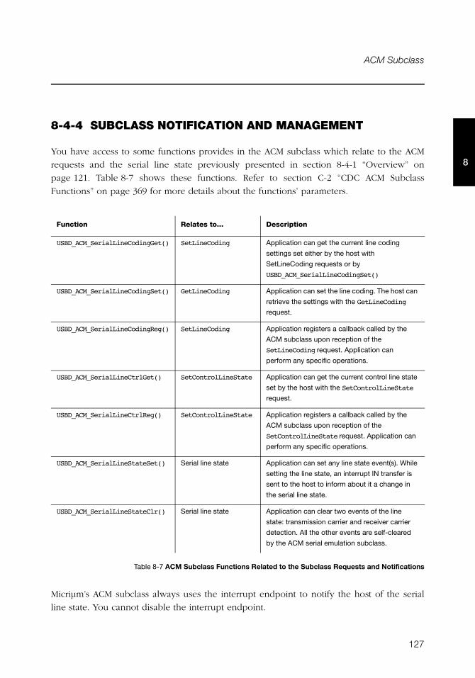
127
ACM Subclass
8
8-4-4 SUBCLASS NOTIFICATION AND MANAGEMENT
You have access to some functions provides in the ACM subclass which relate to the ACM
requests and the serial line state previously presented in section 8-4-1 “Overview” on
page 121. Table 8-7 shows these functions. Refer to section C-2 “CDC ACM Subclass
Functions” on page 369 for more details about the functions’ parameters.
Table 8-7 ACM Subclass Functions Related to the Subclass Requests and Notifications
Micriμm’s ACM subclass always uses the interrupt endpoint to notify the host of the serial
line state. You cannot disable the interrupt endpoint.
Function Relates to... Description
USBD_ACM_SerialLineCodingGet() SetLineCoding Application can get the current line coding
settings set either by the host with
SetLineCoding requests or by
USBD_ACM_SerialLineCodingSet()
USBD_ACM_SerialLineCodingSet() GetLineCoding Application can set the line coding. The host can
retrieve the settings with the GetLineCoding
request.
USBD_ACM_SerialLineCodingReg() SetLineCoding Application registers a callback called by the
ACM subclass upon reception of the
SetLineCoding request. Application can
perform any specific operations.
USBD_ACM_SerialLineCtrlGet() SetControlLineState Application can get the current control line state
set by the host with the SetControlLineState
request.
USBD_ACM_SerialLineCtrlReg() SetControlLineState Application registers a callback called by the
ACM subclass upon reception of the
SetControlLineState request. Application can
perform any specific operations.
USBD_ACM_SerialLineStateSet() Serial line state Application can set any line state event(s). While
setting the line state, an interrupt IN transfer is
sent to the host to inform about it a change in
the serial line state.
USBD_ACM_SerialLineStateClr() Serial line state Application can clear two events of the line
state: transmission carrier and receiver carrier
detection. All the other events are self-cleared
by the ACM serial emulation subclass.
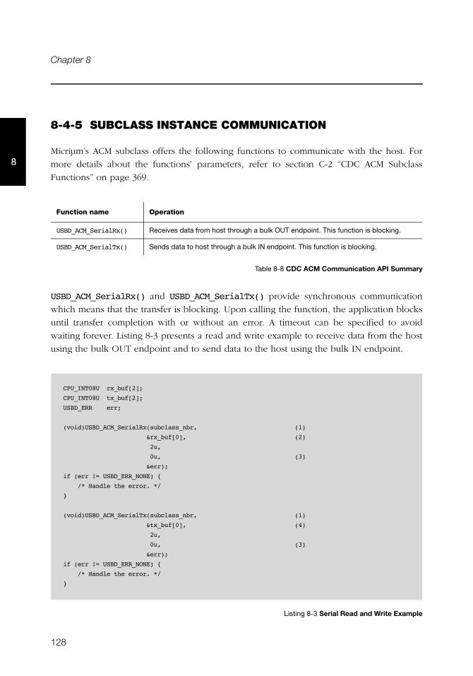
128
Chapter 8
8
8-4-5 SUBCLASS INSTANCE COMMUNICATION
Micriμm’s ACM subclass offers the following functions to communicate with the host. For
more details about the functions’ parameters, refer to section C-2 “CDC ACM Subclass
Functions” on page 369.
Table 8-8 CDC ACM Communication API Summary
USBD_ACM_SerialRx() and USBD_ACM_SerialTx() provide synchronous communication
which means that the transfer is blocking. Upon calling the function, the application blocks
until transfer completion with or without an error. A timeout can be specified to avoid
waiting forever. Listing 8-3 presents a read and write example to receive data from the host
using the bulk OUT endpoint and to send data to the host using the bulk IN endpoint.
Listing 8-3 Serial Read and Write Example
Function name Operation
USBD_ACM_SerialRx() Receives data from host through a bulk OUT endpoint. This function is blocking.
USBD_ACM_SerialTx() Sends data to host through a bulk IN endpoint. This function is blocking.
CPU_INT08U rx_buf[2];
CPU_INT08U tx_buf[2];
USBD_ERR err;
(void)USBD_ACM_SerialRx(subclass_nbr, (1)
&rx_buf[0], (2)
2u,
0u, (3)
&err);
if (err != USBD_ERR_NONE) {
/* Handle the error. */
}
(void)USBD_ACM_SerialTx(subclass_nbr, (1)
&tx_buf[0], (4)
2u,
0u, (3)
&err);
if (err != USBD_ERR_NONE) {
/* Handle the error. */
}
129
ACM Subclass
8
L8-3(1) The class instance number created with USBD_ACM_SerialAdd() will serve
internally to the ACM subclass to route the transfer to the proper bulk OUT or
IN endpoint.
L8-3(2) The application must ensure that the buffer provided to the function is large
enough to accommodate all the data. Otherwise, synchronization issues might
happen.
L8-3(3) In order to avoid an infinite blocking situation, a timeout expressed in
milliseconds can be specified. A value of ‘0’ makes the application task wait
forever.
L8-3(4) The application provides the initialized transmit buffer.
8-4-6 USING THE DEMO APPLICATION
Micriμm provides a demo application that lets you test and evaluate the class
implementation. Source template files are provided for the device.
CONFIGURING DEVICE APPLICATION
The serial demo allows you to send and/or receive serial data to and/or from the device
through a virtual COM port. The demo is implemented in the application file,
app_usbd_cdc.c, provided for μC/OS-II and μC/OS-III. app_usbd_cdc.c is located in
these two folders:
■ \Micrium\Software\uC-USB-Device-V4\App\Device\OS\uCOS-II
■ \Micrium\Software\uC-USB-Device-V4\App\Device\OS\uCOS-III
130
Chapter 8
8
Table 8-9 describes the constants usually defined in app_cfg.h which allows you to use the
serial demo.
Table 8-9 Device Application Configuration Constants
RUNNING THE DEMO APPLICATION
In this section, we will assume Windows as the host operating system. Upon connection of
your CDC ACM device, Windows will enumerate your device and load the native driver
usbser.sys to handle the device communication. The first time you connect your device to
the host, you will have to indicate to Windows which driver to load using an INF file (refer
to section 3-1-1 “About INF Files” on page 46 for more details about INF). The INF file tells
Windows to load the usbser.sys driver. Indicating the INF file to Windows has to be done
only once. Windows will then automatically recognize the CDC ACM device and load the
proper driver for any new connection. The process of indicating the INF file may vary
according to the Windows operating system version:
■ Windows XP directly opens the Found New Hardware Wizard. Follow the different steps
of the wizard until you reach the page where you can indicate the path of the INF file.
■ Windows Vista and later won’t open a “Found New Hardware Wizard”. It will just
indicate that no driver was found for the vendor device. You have to manually open the
wizard. When you open the Device Manager, your CDC ACM device should appear
with a yellow icon. Right-click on your device and choose ‘Update Driver Software...’ to
open the wizard. Follow the different steps of the wizard until the page where you can
indicate the path of the INF file.
Constant Description
APP_CFG_USBD_CDC_EN General constant to enable the CDC ACM demo application.
Must be set to DEF_ENABLED.
APP_CFG_USBD_CDC_SERIAL_TEST_EN Constant to enable the serial demo. Must be set to
DEF_ENABLED.
APP_CFG_USBD_CDC_SERIAL_TASK_PRIO Priority of the task used by the serial demo.
APP_CFG_USBD_CDC_SERIAL_TASK_STK_SIZE Stack size of the task used by the serial demo. A default
value can be 256.
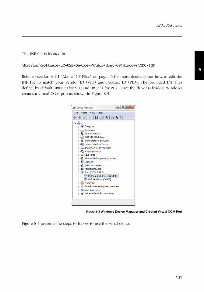
131
ACM Subclass
8
The INF file is located in:
\Micrium\Software\uC-USB-Device-V4\App\Host\OS\Windows\CDC\INF
Refer to section 3-1-1 “About INF Files” on page 46 for more details about how to edit the
INF file to match your Vendor ID (VID) and Product ID (PID). The provided INF files
define, by default, 0xFFFE for VID and 0x1234 for PID. Once the driver is loaded, Windows
creates a virtual COM port as shown in Figure 8-3.
Figure 8-3 Windows Device Manager and Created Virtual COM Port
Figure 8-4 presents the steps to follow to use the serial demo.
132
Chapter 8
8
Figure 8-4 Serial Demo
F8-4(1) Open a serial terminal (for instance, HyperTerminal). Open the COM port
matching to your CDC ACM device with the serial settings (baud rate, stop
bits, parity and data bits) you want. This operation will send a series of CDC
ACM class-specific requests (GET_LINE_CODING, SET_LINE_CODING,
SET_CONTROL_LINE_STATE) to your device. Note that Windows Vista and later
don’t provide HyperTerminal anymore. You may use other free serial
terminals such TeraTerm (http://ttssh2.sourceforge.jp/), Hercules
(http://www.hw-group.com/products/hercules/index_en.html),
RealTerm (http://realterm.sourceforge.net/), etc.
F8-4(2) In order to start the communication with the serial task on the device side, the
Data Terminal Ready (DTR) signal must be set and sent to the device. The DTR
signal prevents the serial task from sending characters if the terminal is not
ready to receive data. Sending the DTR signal may vary depending on your
serial terminal. For example, HyperTerminal sends a properly set DTR signal
automatically upon opening of the COM port. Hercules terminal allows you to
set and clear the DTR signal from the graphical user interface (GUI) with a
checkbox. Other terminals do not permit to set/clear DTR or the DTR set/
clear’s functionality is difficult to find and to use.
F8-4(3) Once the serial task receives the DTR signal, the task sends a menu to the serial
terminal with two options as presented in Figure 8-5.
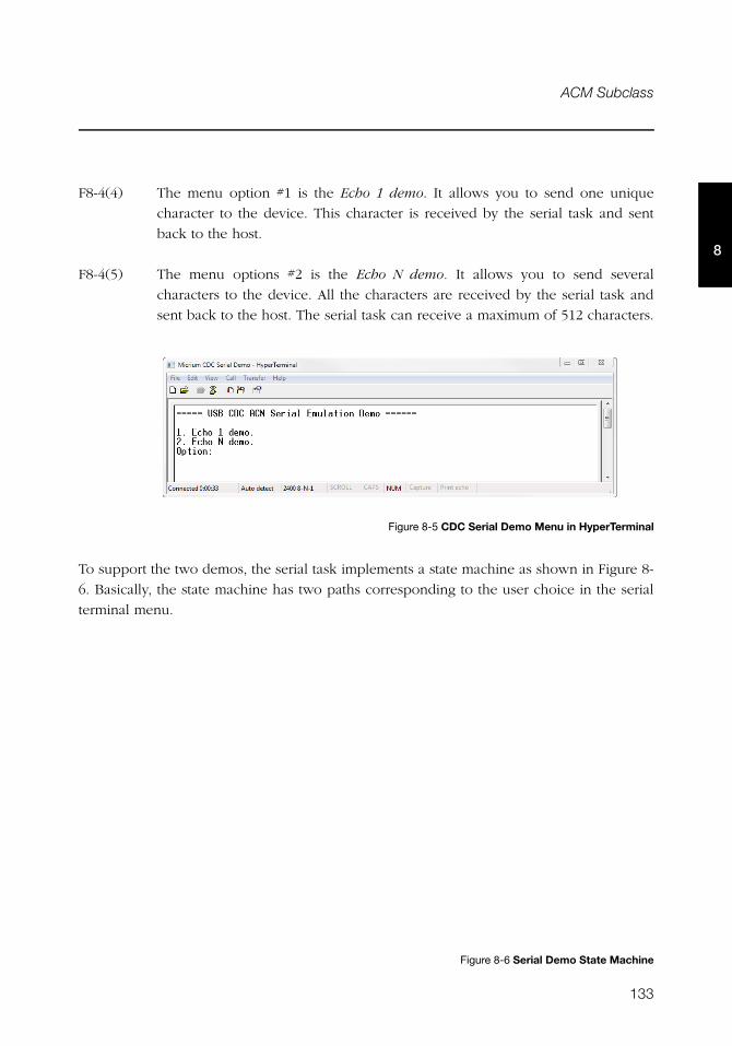
133
ACM Subclass
8
F8-4(4) The menu option #1 is the Echo 1 demo. It allows you to send one unique
character to the device. This character is received by the serial task and sent
back to the host.
F8-4(5) The menu options #2 is the Echo N demo. It allows you to send several
characters to the device. All the characters are received by the serial task and
sent back to the host. The serial task can receive a maximum of 512 characters.
Figure 8-5 CDC Serial Demo Menu in HyperTerminal
To support the two demos, the serial task implements a state machine as shown in Figure 8-
6. Basically, the state machine has two paths corresponding to the user choice in the serial
terminal menu.
Figure 8-6 Serial Demo State Machine
134
Chapter 8
8
F8-6(1) Once the DTR signal has been received, the serial task is in the MENU state.
F8-6(2) If you choose the menu option #1, the serial task will echo back any single
character sent by the serial terminal as long as “Ctrl+C” is not pressed.
F8-6(3) If you choose the menu option #2, the serial task will echo all the received
characters sent by the serial terminal as long as “Ctrl+C” is not pressed.
Table 8-10 shows four possible serial terminals which you may use to test the CDC ACM
class.
Table 8-10 Serial Terminals and CDC Serial Demo
Terminal DTR set/clearMenu option(s)
usable
HyperTerminal Yes (properly set DTR signal automatically sent upon COM port
opening)
1 and 2
Hercules Yes (a checkbox in the GUI allows you to set/clear DTR) 1 and 2
RealTerm Yes (Set/Clear DTR buttons in the GUI) 1 and 2
TeraTerm Yes (DTR can be set using a macro. GUI does NOT allows you to set/
clear DTR easily)
1 and 2
135
Chapter
9Human Interface Device Class
This chapter describes the Human Interface Device (HID) class supported by
μC/USB-Device. The HID implementation complies with the following specifications:
■ Device Class Definition for Human Interface Devices (HID), 6/27/01, Version 1.11.
■ Universal Serial Bus HID Usage Tables, 10/28/2004, Version 1.12.
The HID class encompasses devices used by humans to control computer operations.
Keyboards, mice, pointing devices, game devices are some examples of typical HID devices.
The HID class can also be used in a composite device that contains some controls such as
knobs, switches, buttons and sliders. For instance, mute and volume controls in an audio
headset are controlled by the HID function of the headset. The headset also has an audio
function. HID data can exchange data for any purpose using only control and interrupt
transfers. The HID class is one of the oldest and most popular USB classes. All the major
host operating systems provide a native driver to manage HID devices. That’s why a variety
of vendor-specific devices work with the HID class. This class also includes various types of
output directed to the user information (e.g. LEDs on a keyboard).
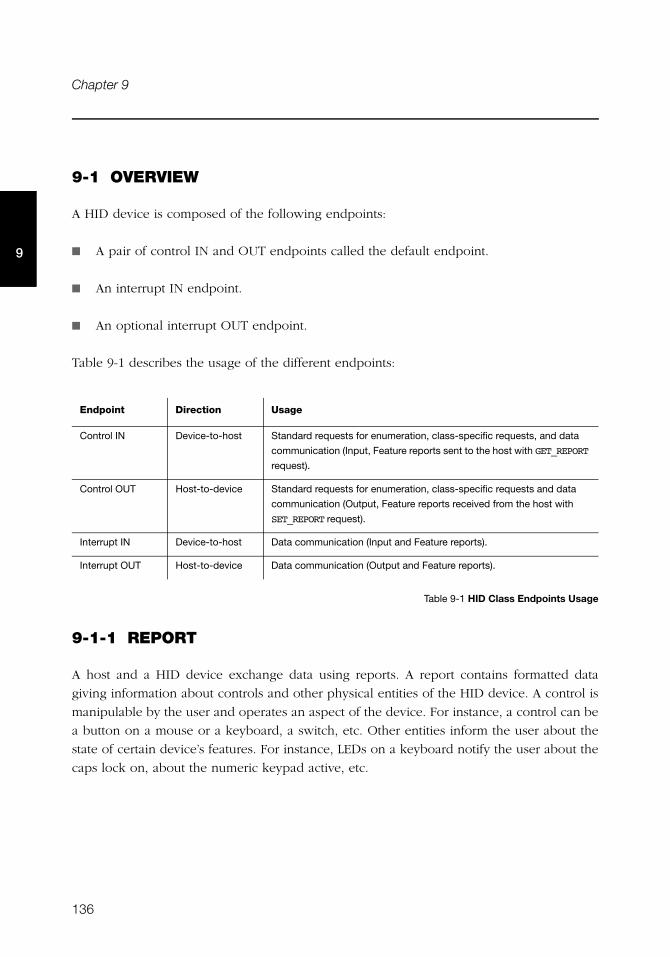
136
Chapter 9
9
9-1 OVERVIEW
A HID device is composed of the following endpoints:
■ A pair of control IN and OUT endpoints called the default endpoint.
■ An interrupt IN endpoint.
■ An optional interrupt OUT endpoint.
Table 9-1 describes the usage of the different endpoints:
Table 9-1 HID Class Endpoints Usage
9-1-1 REPORT
A host and a HID device exchange data using reports. A report contains formatted data
giving information about controls and other physical entities of the HID device. A control is
manipulable by the user and operates an aspect of the device. For instance, a control can be
a button on a mouse or a keyboard, a switch, etc. Other entities inform the user about the
state of certain device’s features. For instance, LEDs on a keyboard notify the user about the
caps lock on, about the numeric keypad active, etc.
Endpoint Direction Usage
Control IN Device-to-host Standard requests for enumeration, class-specific requests, and data
communication (Input, Feature reports sent to the host with GET_REPORT
request).
Control OUT Host-to-device Standard requests for enumeration, class-specific requests and data
communication (Output, Feature reports received from the host with
SET_REPORT request).
Interrupt IN Device-to-host Data communication (Input and Feature reports).
Interrupt OUT Host-to-device Data communication (Output and Feature reports).
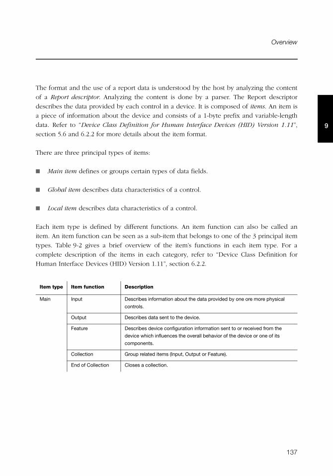
137
Overview
9
The format and the use of a report data is understood by the host by analyzing the content
of a Report descriptor. Analyzing the content is done by a parser. The Report descriptor
describes the data provided by each control in a device. It is composed of items. An item is
a piece of information about the device and consists of a 1-byte prefix and variable-length
data. Refer to “Device Class Definition for Human Interface Devices (HID) Version 1.11”,
section 5.6 and 6.2.2 for more details about the item format.
There are three principal types of items:
■ Main item defines or groups certain types of data fields.
■ Global item describes data characteristics of a control.
■ Local item describes data characteristics of a control.
Each item type is defined by different functions. An item function can also be called an
item. An item function can be seen as a sub-item that belongs to one of the 3 principal item
types. Table 9-2 gives a brief overview of the item’s functions in each item type. For a
complete description of the items in each category, refer to “Device Class Definition for
Human Interface Devices (HID) Version 1.11”, section 6.2.2.
Item type Item function Description
Main Input Describes information about the data provided by one ore more physical
controls.
Output Describes data sent to the device.
Feature Describes device configuration information sent to or received from the
device which influences the overall behavior of the device or one of its
components.
Collection Group related items (Input, Output or Feature).
End of Collection Closes a collection.
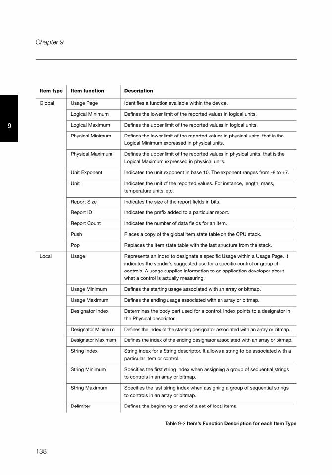
138
Chapter 9
9
Table 9-2 Item’s Function Description for each Item Type
Global Usage Page Identifies a function available within the device.
Logical Minimum Defines the lower limit of the reported values in logical units.
Logical Maximum Defines the upper limit of the reported values in logical units.
Physical Minimum Defines the lower limit of the reported values in physical units, that is the
Logical Minimum expressed in physical units.
Physical Maximum Defines the upper limit of the reported values in physical units, that is the
Logical Maximum expressed in physical units.
Unit Exponent Indicates the unit exponent in base 10. The exponent ranges from -8 to +7.
Unit Indicates the unit of the reported values. For instance, length, mass,
temperature units, etc.
Report Size Indicates the size of the report fields in bits.
Report ID Indicates the prefix added to a particular report.
Report Count Indicates the number of data fields for an item.
Push Places a copy of the global item state table on the CPU stack.
Pop Replaces the item state table with the last structure from the stack.
Local Usage Represents an index to designate a specific Usage within a Usage Page. It
indicates the vendor’s suggested use for a specific control or group of
controls. A usage supplies information to an application developer about
what a control is actually measuring.
Usage Minimum Defines the starting usage associated with an array or bitmap.
Usage Maximum Defines the ending usage associated with an array or bitmap.
Designator Index Determines the body part used for a control. Index points to a designator in
the Physical descriptor.
Designator Minimum Defines the index of the starting designator associated with an array or bitmap.
Designator Maximum Defines the index of the ending designator associated with an array or bitmap.
String Index String index for a String descriptor. It allows a string to be associated with a
particular item or control.
String Minimum Specifies the first string index when assigning a group of sequential strings
to controls in an array or bitmap.
String Maximum Specifies the last string index when assigning a group of sequential strings
to controls in an array or bitmap.
Delimiter Defines the beginning or end of a set of local items.
Item type Item function Description
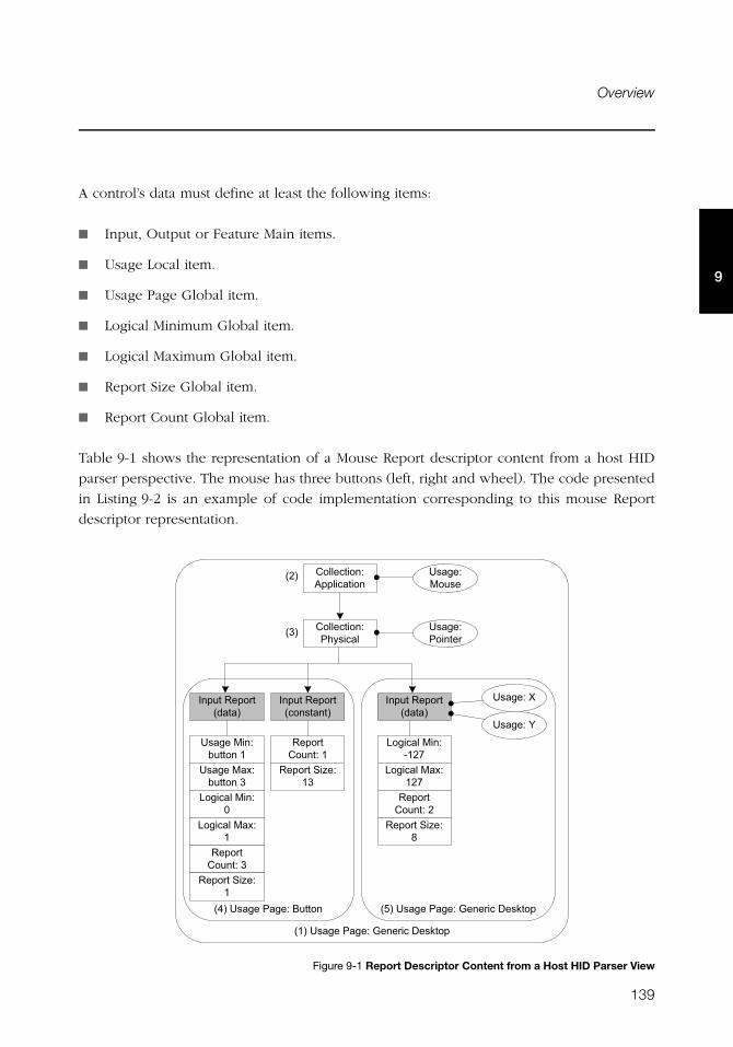
139
Overview
9
A control’s data must define at least the following items:
■ Input, Output or Feature Main items.
■ Usage Local item.
■ Usage Page Global item.
■ Logical Minimum Global item.
■ Logical Maximum Global item.
■ Report Size Global item.
■ Report Count Global item.
Table 9-1 shows the representation of a Mouse Report descriptor content from a host HID
parser perspective. The mouse has three buttons (left, right and wheel). The code presented
in Listing 9-2 is an example of code implementation corresponding to this mouse Report
descriptor representation.
Figure 9-1 Report Descriptor Content from a Host HID Parser View
�0���!��������&�9��� �����!"���
�:���!��������&������� �;���!��������&�9��� �����!"���
����������&'����������
����������&��.<!����
�!���&�6��!�
�!���&�������
��������� ��������
��������� �����!�����
��������� �������
�!���&�=
�!���&�>
?�������6��&�-0/@
?�������6�&�0/@
��� �������&�/
��� ����A�&�B
��� �������&�0
��� ����A�&�01
�!����6��&�#������0
�!����6�&�#������1
?�������6��&�)
?�������6�&�0
��� �������&�1
��� ����A�&�0
�/�
�1�
140
Chapter 9
9
F9-1(1) The Usage Page item function specifies the general function of the device. In
this example, the HID device belongs to a generic desktop control.
F9-1(2) The Collection Application groups Main items that have a common purpose
and may be familiar to applications. In the diagram, the group is composed of
three Input Main items. For this collection, the suggested use for the controls is
a mouse as indicated by the Usage item.
F9-1(3) Nested collections may be used to give more details about the use of a single
control or group of controls to applications. In this example, the Collection
Physical, nested into the Collection Application, is composed of the same 3
Input items forming the Collection Application. The Collection Physical is used
for a set of data items that represent data points collected at one geometric
point. In the example, the suggested use is a pointer as indicated by the Usage
item. Here the pointer usage refers to the mouse position coordinates and the
system software will translate the mouse coordinates in movement of the
screen cursor.
F9-1(4) Nested usage pages are also possible and give more details about a certain
aspect within the general function of the device. In this case, two Inputs items
are grouped and correspond to the buttons of the mouse. One Input item
defines the three buttons of the mouse (right, left and wheel) in terms of
number of data fields for the item (Report Count item), size of a data field
(Report Size item) and possible values for each data field (Usage Minimum and
Maximum, Logical Minimum and Maximum items). The other Input item is a
13-bit constant allowing the Input report data to be aligned on a byte
boundary. This Input item is used only for padding purpose.
F9-1(5) Another nested usage page referring to a generic desktop control is defined for the
mouse position coordinates. For this usage page, the Input item describes the data
fields corresponding to the x- and y-axis as specified by the two Usage items.
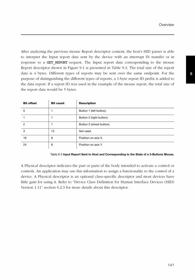
141
Overview
9
After analyzing the previous mouse Report descriptor content, the host’s HID parser is able
to interpret the Input report data sent by the device with an interrupt IN transfer or in
response to a GET_REPORT request. The Input report data corresponding to the mouse
Report descriptor shown in Figure 9-1 is presented in Table 9-3. The total size of the report
data is 4 bytes. Different types of reports may be sent over the same endpoint. For the
purpose of distinguishing the different types of reports, a 1-byte report ID prefix is added to
the data report. If a report ID was used in the example of the mouse report, the total size of
the report data would be 5 bytes.
Table 9-3 Input Report Sent to Host and Corresponding to the State of a 3-Buttons Mouse.
A Physical descriptor indicates the part or parts of the body intended to activate a control or
controls. An application may use this information to assign a functionality to the control of a
device. A Physical descriptor is an optional class-specific descriptor and most devices have
little gain for using it. Refer to “Device Class Definition for Human Interface Devices (HID)
Version 1.11” section 6.2.3 for more details about this descriptor.
Bit offset Bit count Description
0 1 Button 1 (left button).
1 1 Button 2 (right button).
2 1 Button 3 (wheel button).
3 13 Not used.
16 8 Position on axis X.
24 8 Position on axis Y.
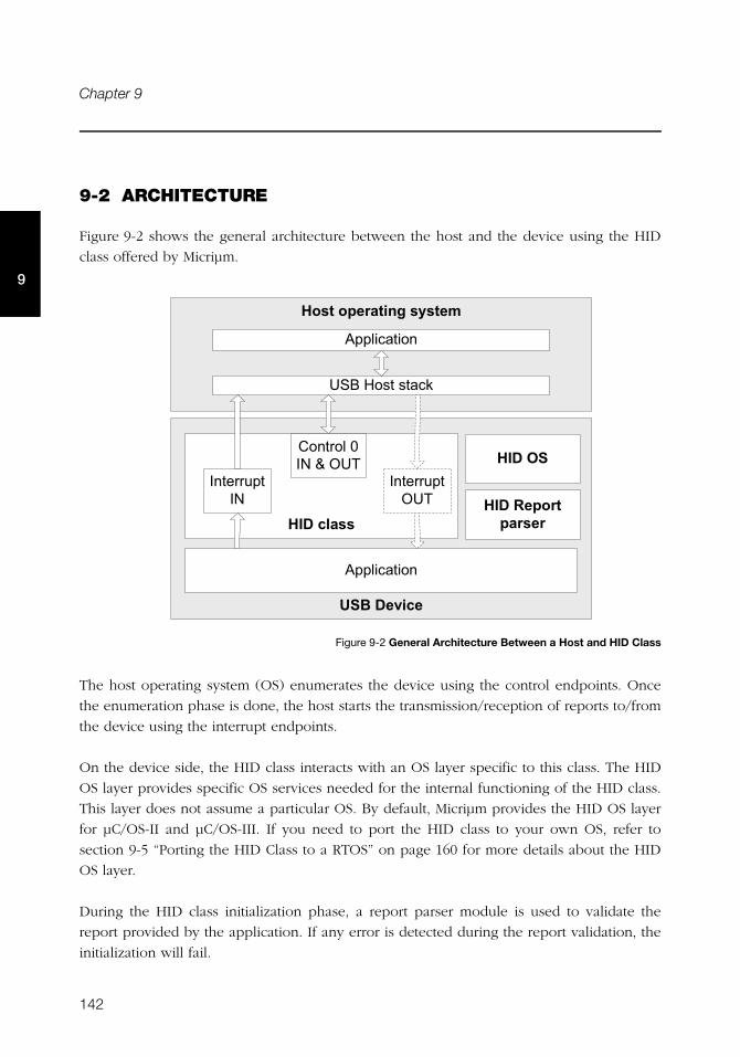
142
Chapter 9
9
9-2 ARCHITECTURE
Figure 9-2 shows the general architecture between the host and the device using the HID
class offered by Micriμm.
Figure 9-2 General Architecture Between a Host and HID Class
The host operating system (OS) enumerates the device using the control endpoints. Once
the enumeration phase is done, the host starts the transmission/reception of reports to/from
the device using the interrupt endpoints.
On the device side, the HID class interacts with an OS layer specific to this class. The HID
OS layer provides specific OS services needed for the internal functioning of the HID class.
This layer does not assume a particular OS. By default, Micriμm provides the HID OS layer
for μC/OS-II and μC/OS-III. If you need to port the HID class to your own OS, refer to
section 9-5 “Porting the HID Class to a RTOS” on page 160 for more details about the HID
OS layer.
During the HID class initialization phase, a report parser module is used to validate the
report provided by the application. If any error is detected during the report validation, the
initialization will fail.
� ��� !�" ���#��$���%
'����������
������!��!���"
&'(�������
'����������
������ ��
���� ����*
���� �����+�
���� ���)�*�3�+�
����0�! "��! "��"
�����'
143
Configuration
9
9-3 CONFIGURATION
9-3-1 GENERAL CONFIGURATION
Some constants are available to customize the class. These constants are located in the USB
device configuration file, usbd_cfg.h . Table 9-4 shows their description.
Table 9-4 HID Class Configuration Constants
The HID class uses an internal class to manage periodic input reports. The task priority and
stack size shown in Table 9-5 are defined in the application configuration file, app_cfg.h.
Refer to section 9-6 “Periodic Input Reports Task” on page 161 for more details about the
HID internal task.
Table 9-5 HID Internal Task’s Configuration Constants
Constant Description
USBD_HID_CFG_MAX_NBR_DEV Configures the maximum number of class instances. Unless you plan
on having multiple configurations or interfaces using different class
instances, this can be set to 1.
USBD_HID_CFG_MAX_NBR_CFG Configures the maximum number of configurations in which HID class
is used. Keep in mind that if you use a high-speed device, two
configurations will be built, one for full-speed and another for
high-speed.
USBD_HID_CFG_MAX_NBR_REPORT_ID Configures the maximum number of report IDs allowed in a report. The
value should be set properly to accommodate the number of report ID
to be used in the report. The minimum value is 1.
USBD_HID_CFG_MAX_NBR_REPORT_PUSHPOP Configures the maximum number of Push and Pop items used in a
report. If the constant is set to 0, no Push and Pop items are present in
the report.
Constant Description
USBD_HID_OS_CFG_TMR_TASK_PRIO Configures the priority of the HID periodic input reports task.
USBD_HID_OS_CFG_TMR_TASK_STK_SIZE Configures the stack size of the HID periodic input reports task.
144
Chapter 9
9
9-3-2 CLASS INSTANCE CONFIGURATION
Before starting the communication phase, your application needs to initialize and configure
the class to suit its needs. Table 9-6 summarizes the initialization functions provided by the
HID class. For more details about the functions parameters, refer to Appendix D, “HID API
Reference” on page 387.
Table 9-6 HID Class Initialization API Summary
You need to call these functions in the order shown below to successfully initialize the HID
class:
1 Call USBD_HID_Init()
This is the first function you should call and you should do it only once even if you use
multiple class instances. This function initializes all internal structures and variables that
the class needs and also the HID OS layer.
2 Call USBD_HID_Add()
This function allocates an HID class instance. It also allows you to specify the following
instance characteristics:
■ The country code of the localized HID hardware.
■ The Report descriptor content and size.
■ The Physical descriptor content and size.
■ The polling internal for the interrupt IN endpoint.
■ The polling internal for the interrupt OUT endpoint.
Function name Operation
USBD_HID_Init() Initializes HID class internal structures, variables and the OS layer.
USBD_HID_Add() Creates a new instance of HID class.
USBD_HID_CfgAdd() Adds an existing HID instance to the specified device configuration.
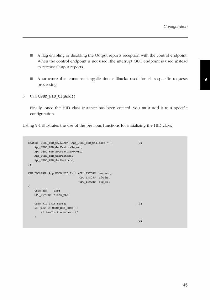
145
Configuration
9
■ A flag enabling or disabling the Output reports reception with the control endpoint.
When the control endpoint is not used, the interrupt OUT endpoint is used instead
to receive Output reports.
■ A structure that contains 4 application callbacks used for class-specific requests
processing.
3 Call USBD_HID_CfgAdd()
Finally, once the HID class instance has been created, you must add it to a specific
configuration.
Listing 9-1 illustrates the use of the previous functions for initializing the HID class.
static USBD_HID_CALLBACK App_USBD_HID_Callback = { (3)
App_USBD_HID_GetFeatureReport,
App_USBD_HID_SetFeatureReport,
App_USBD_HID_GetProtocol,
App_USBD_HID_SetProtocol,
};
CPU_BOOLEAN App_USBD_HID_Init (CPU_INT08U dev_nbr,
CPU_INT08U cfg_hs,
CPU_INT08U cfg_fs)
{
USBD_ERR err;
CPU_INT08U class_nbr;
USBD_HID_Init(&err); (1)
if (err != USBD_ERR_NONE) {
/* Handle the error. */
}
(2)
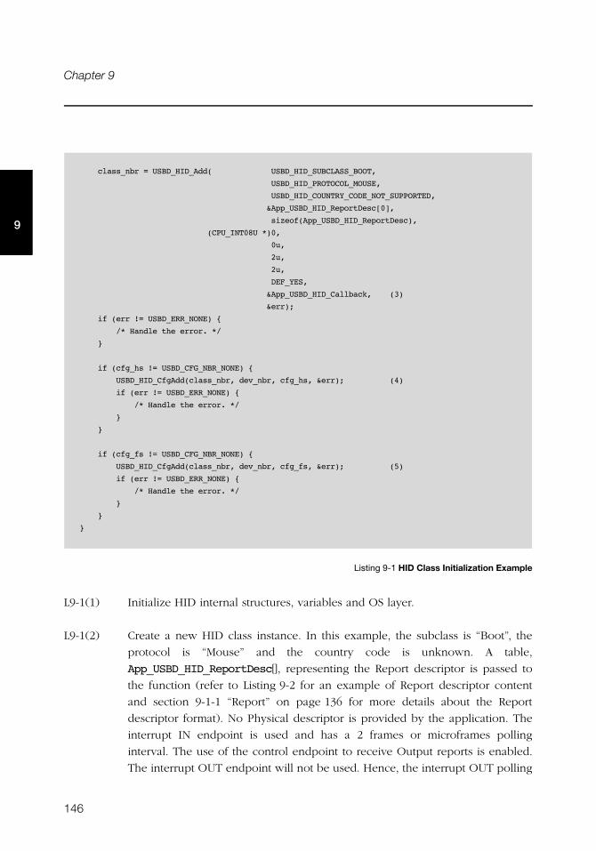
146
Chapter 9
9
Listing 9-1 HID Class Initialization Example
L9-1(1) Initialize HID internal structures, variables and OS layer.
L9-1(2) Create a new HID class instance. In this example, the subclass is “Boot”, the
protocol is “Mouse” and the country code is unknown. A table,
App_USBD_HID_ReportDesc[], representing the Report descriptor is passed to
the function (refer to Listing 9-2 for an example of Report descriptor content
and section 9-1-1 “Report” on page 136 for more details about the Report
descriptor format). No Physical descriptor is provided by the application. The
interrupt IN endpoint is used and has a 2 frames or microframes polling
interval. The use of the control endpoint to receive Output reports is enabled.
The interrupt OUT endpoint will not be used. Hence, the interrupt OUT polling
class_nbr = USBD_HID_Add( USBD_HID_SUBCLASS_BOOT,
USBD_HID_PROTOCOL_MOUSE,
USBD_HID_COUNTRY_CODE_NOT_SUPPORTED,
&App_USBD_HID_ReportDesc[0],
sizeof(App_USBD_HID_ReportDesc),
(CPU_INT08U *)0,
0u,
2u,
2u,
DEF_YES,
&App_USBD_HID_Callback, (3)
&err);
if (err != USBD_ERR_NONE) {
/* Handle the error. */
}
if (cfg_hs != USBD_CFG_NBR_NONE) {
USBD_HID_CfgAdd(class_nbr, dev_nbr, cfg_hs, &err); (4)
if (err != USBD_ERR_NONE) {
/* Handle the error. */
}
}
if (cfg_fs != USBD_CFG_NBR_NONE) {
USBD_HID_CfgAdd(class_nbr, dev_nbr, cfg_fs, &err); (5)
if (err != USBD_ERR_NONE) {
/* Handle the error. */
}
}
}
147
Configuration
9
interval of 2 is ignored by the class. The structure App_USBD_HID_Callback is
also passed and references 4 application callbacks which will be called by the
HID class upon processing of the class-specific requests.
L9-1(3) There are 4 application callbacks for class-specific requests processing. There is
one callback for each of the following requests: GET_REPORT, SET_REPORT,
GET_PROTOCOL and SET_PROTOCOL. Refer to “Device Class Definition for
Human Interface Devices (HID) Version 1.11”, section 7.2 for more details
about these class-specific requests.
L9-1(4) Check if the high-speed configuration is active and proceed to add the HID
instance previously created to this configuration.
L9-1(5) Check if the full-speed configuration is active and proceed to add the HID
instance to this configuration.
Listing 9-1 also illustrates an example of multiple configurations. The functions
USBD_HID_Add() and USBD_HID_CfgAdd() allow you to create multiple configurations and
multiple instances architecture. Refer to section Table 7-1 “Constants and Functions Related
to the Concept of Multiple Class Instances” on page 99 for more details about multiple class
instances.
Listing 9-2 presents an example of table declaration defining a Report descriptor
corresponding to a mouse. The example matches the mouse report descriptor viewed by
the host HID parser in Figure 9-1. The mouse report represents an Input report. Refer to
section 9-1-1 “Report” on page 136 for more details about the Report descriptor format. The
items inside a collection are intentionally indented for code clarity.
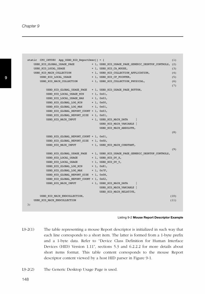
148
Chapter 9
9
Listing 9-2 Mouse Report Descriptor Example
L9-2(1) The table representing a mouse Report descriptor is initialized in such way that
each line corresponds to a short item. The latter is formed from a 1-byte prefix
and a 1-byte data. Refer to “Device Class Definition for Human Interface
Devices (HID) Version 1.11”, sections 5.3 and 6.2.2.2 for more details about
short items format. This table content corresponds to the mouse Report
descriptor content viewed by a host HID parser in Figure 9-1.
L9-2(2) The Generic Desktop Usage Page is used.
static CPU_INT08U App_USBD_HID_ReportDesc[] = { (1)
USBD_HID_GLOBAL_USAGE_PAGE + 1, USBD_HID_USAGE_PAGE_GENERIC_DESKTOP_CONTROLS, (2)
USBD_HID_LOCAL_USAGE + 1, USBD_HID_CA_MOUSE, (3)
USBD_HID_MAIN_COLLECTION + 1, USBD_HID_COLLECTION_APPLICATION, (4)
USBD_HID_LOCAL_USAGE + 1, USBD_HID_CP_POINTER, (5)
USBD_HID_MAIN_COLLECTION + 1, USBD_HID_COLLECTION_PHYSICAL, (6)
(7)
USBD_HID_GLOBAL_USAGE_PAGE + 1, USBD_HID_USAGE_PAGE_BUTTON,
USBD_HID_LOCAL_USAGE_MIN + 1, 0x01,
USBD_HID_LOCAL_USAGE_MAX + 1, 0x03,
USBD_HID_GLOBAL_LOG_MIN + 1, 0x00,
USBD_HID_GLOBAL_LOG_MAX + 1, 0x01,
USBD_HID_GLOBAL_REPORT_COUNT + 1, 0x03,
USBD_HID_GLOBAL_REPORT_SIZE + 1, 0x01,
USBD_HID_MAIN_INPUT + 1, USBD_HID_MAIN_DATA |
USBD_HID_MAIN_VARIABLE |
USBD_HID_MAIN_ABSOLUTE,
(8)
USBD_HID_GLOBAL_REPORT_COUNT + 1, 0x01,
USBD_HID_GLOBAL_REPORT_SIZE + 1, 0x0D,
USBD_HID_MAIN_INPUT + 1, USBD_HID_MAIN_CONSTANT,
(9)
USBD_HID_GLOBAL_USAGE_PAGE + 1, USBD_HID_USAGE_PAGE_GENERIC_DESKTOP_CONTROLS,
USBD_HID_LOCAL_USAGE + 1, USBD_HID_DV_X,
USBD_HID_LOCAL_USAGE + 1, USBD_HID_DV_Y,
USBD_HID_GLOBAL_LOG_MIN + 1, 0x81,
USBD_HID_GLOBAL_LOG_MAX + 1, 0x7F,
USBD_HID_GLOBAL_REPORT_SIZE + 1, 0x08,
USBD_HID_GLOBAL_REPORT_COUNT + 1, 0x02,
USBD_HID_MAIN_INPUT + 1, USBD_HID_MAIN_DATA |
USBD_HID_MAIN_VARIABLE |
USBD_HID_MAIN_RELATIVE,
USBD_HID_MAIN_ENDCOLLECTION, (10)
USBD_HID_MAIN_ENDCOLLECTION (11)
};
149
Configuration
9
L9-2(3) Within the Generic Desktop Usage Page, the usage tag suggests that the group
of controls is for controlling a mouse. A mouse collection typically consists of
two axes (X and Y) and one, two, or three buttons.
L9-2(4) The mouse collection is started.
L9-2(5) Within the mouse collection, a usage tag suggests more specifically that the
mouse controls belong to the pointer collection. A pointer collection is a
collection of axes that generates a value to direct, indicate, or point user
intentions to an application.
L9-2(6) The pointer collection is started.
L9-2(7) The Buttons Usage Page defines an Input item composed of three 1-bit fields.
Each 1-bit field represents the mouse’s button 1, 2 and 3 respectively and can
return a value of 0 or 1.
L9-2(8) The Input Item for the Buttons Usage Page is padded with 13 other bits.
L9-2(9) Another Generic Desktop Usage Page is indicated for describing the mouse
position with the axes X and Y. The Input item is composed of two 8-bit fields
whose value can be between -127 and 127.
L9-2(10) The pointer collection is closed.
L9-2(11) The mouse collection is closed.
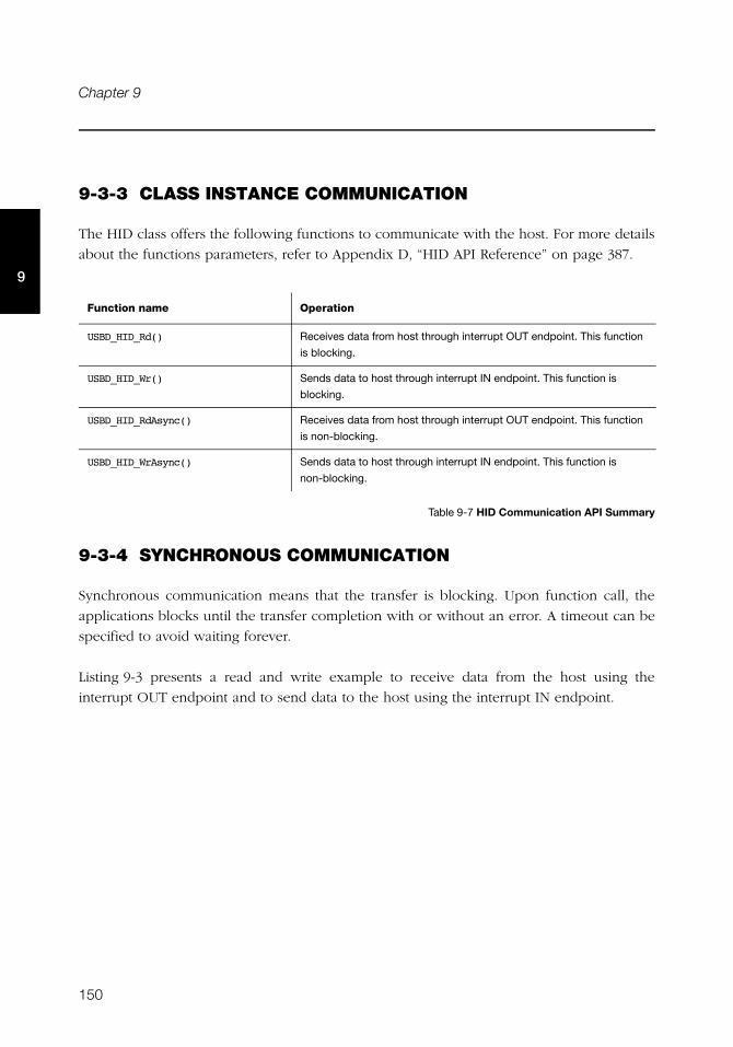
150
Chapter 9
9
9-3-3 CLASS INSTANCE COMMUNICATION
The HID class offers the following functions to communicate with the host. For more details
about the functions parameters, refer to Appendix D, “HID API Reference” on page 387.
Table 9-7 HID Communication API Summary
9-3-4 SYNCHRONOUS COMMUNICATION
Synchronous communication means that the transfer is blocking. Upon function call, the
applications blocks until the transfer completion with or without an error. A timeout can be
specified to avoid waiting forever.
Listing 9-3 presents a read and write example to receive data from the host using the
interrupt OUT endpoint and to send data to the host using the interrupt IN endpoint.
Function name Operation
USBD_HID_Rd() Receives data from host through interrupt OUT endpoint. This function
is blocking.
USBD_HID_Wr() Sends data to host through interrupt IN endpoint. This function is
blocking.
USBD_HID_RdAsync() Receives data from host through interrupt OUT endpoint. This function
is non-blocking.
USBD_HID_WrAsync() Sends data to host through interrupt IN endpoint. This function is
non-blocking.
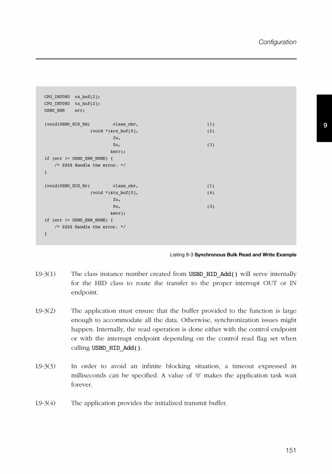
151
Configuration
9
Listing 9-3 Synchronous Bulk Read and Write Example
L9-3(1) The class instance number created from USBD_HID_Add() will serve internally
for the HID class to route the transfer to the proper interrupt OUT or IN
endpoint.
L9-3(2) The application must ensure that the buffer provided to the function is large
enough to accommodate all the data. Otherwise, synchronization issues might
happen. Internally, the read operation is done either with the control endpoint
or with the interrupt endpoint depending on the control read flag set when
calling USBD_HID_Add().
L9-3(3) In order to avoid an infinite blocking situation, a timeout expressed in
milliseconds can be specified. A value of ‘0’ makes the application task wait
forever.
L9-3(4) The application provides the initialized transmit buffer.
CPU_INT08U rx_buf[2];
CPU_INT08U tx_buf[2];
USBD_ERR err;
(void)USBD_HID_Rd( class_nbr, (1)
(void *)&rx_buf[0], (2)
2u,
0u, (3)
&err);
if (err != USBD_ERR_NONE) {
/* $$$$ Handle the error. */
}
(void)USBD_HID_Wr( class_nbr, (1)
(void *)&tx_buf[0], (4)
2u,
0u, (3)
&err);
if (err != USBD_ERR_NONE) {
/* $$$$ Handle the error. */
}
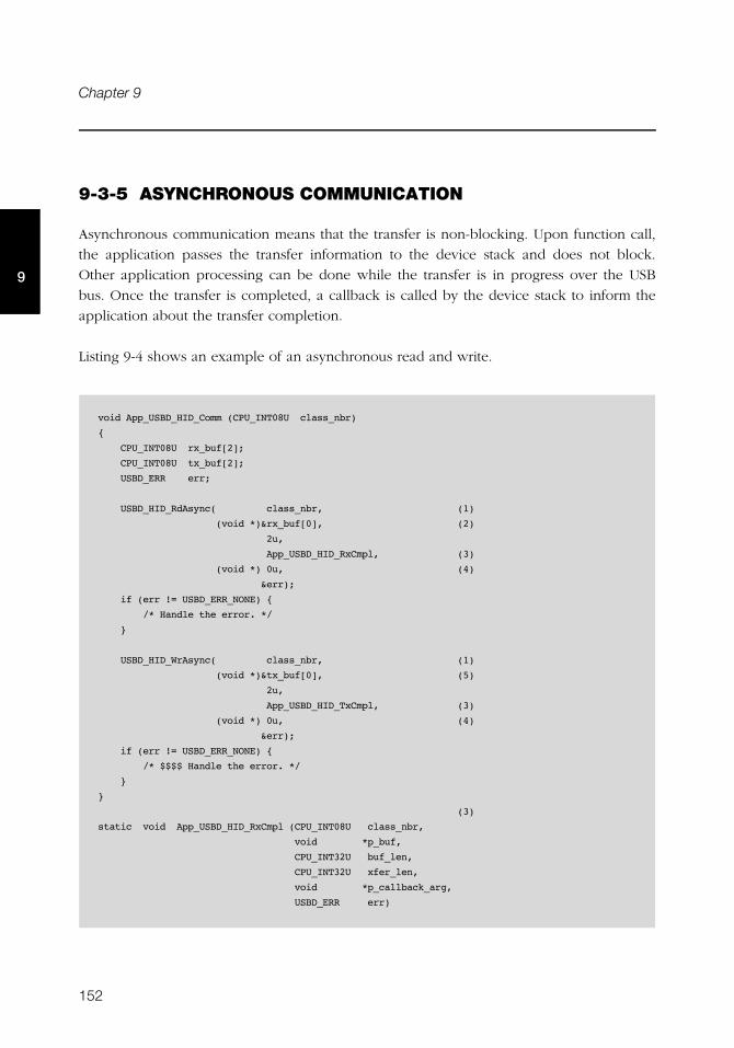
152
Chapter 9
9
9-3-5 ASYNCHRONOUS COMMUNICATION
Asynchronous communication means that the transfer is non-blocking. Upon function call,
the application passes the transfer information to the device stack and does not block.
Other application processing can be done while the transfer is in progress over the USB
bus. Once the transfer is completed, a callback is called by the device stack to inform the
application about the transfer completion.
Listing 9-4 shows an example of an asynchronous read and write.
void App_USBD_HID_Comm (CPU_INT08U class_nbr)
{
CPU_INT08U rx_buf[2];
CPU_INT08U tx_buf[2];
USBD_ERR err;
USBD_HID_RdAsync( class_nbr, (1)
(void *)&rx_buf[0], (2)
2u,
App_USBD_HID_RxCmpl, (3)
(void *) 0u, (4)
&err);
if (err != USBD_ERR_NONE) {
/* Handle the error. */
}
USBD_HID_WrAsync( class_nbr, (1)
(void *)&tx_buf[0], (5)
2u,
App_USBD_HID_TxCmpl, (3)
(void *) 0u, (4)
&err);
if (err != USBD_ERR_NONE) {
/* $$$$ Handle the error. */
}
}
(3)
static void App_USBD_HID_RxCmpl (CPU_INT08U class_nbr,
void *p_buf,
CPU_INT32U buf_len,
CPU_INT32U xfer_len,
void *p_callback_arg,
USBD_ERR err)
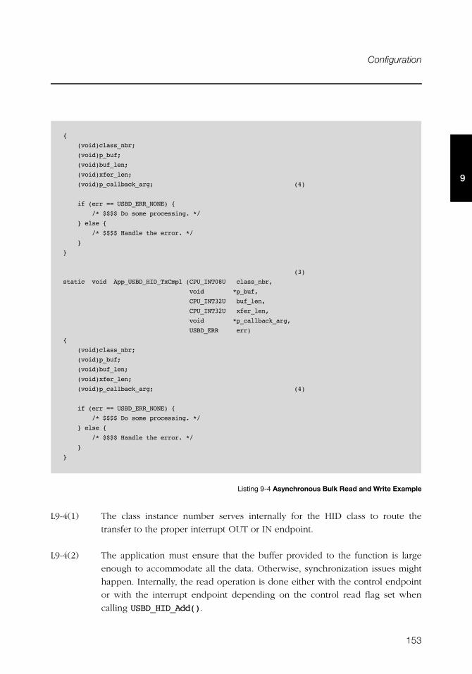
153
Configuration
9
Listing 9-4 Asynchronous Bulk Read and Write Example
L9-4(1) The class instance number serves internally for the HID class to route the
transfer to the proper interrupt OUT or IN endpoint.
L9-4(2) The application must ensure that the buffer provided to the function is large
enough to accommodate all the data. Otherwise, synchronization issues might
happen. Internally, the read operation is done either with the control endpoint
or with the interrupt endpoint depending on the control read flag set when
calling USBD_HID_Add().
{
(void)class_nbr;
(void)p_buf;
(void)buf_len;
(void)xfer_len;
(void)p_callback_arg; (4)
if (err == USBD_ERR_NONE) {
/* $$$$ Do some processing. */
} else {
/* $$$$ Handle the error. */
}
}
(3)
static void App_USBD_HID_TxCmpl (CPU_INT08U class_nbr,
void *p_buf,
CPU_INT32U buf_len,
CPU_INT32U xfer_len,
void *p_callback_arg,
USBD_ERR err)
{
(void)class_nbr;
(void)p_buf;
(void)buf_len;
(void)xfer_len;
(void)p_callback_arg; (4)
if (err == USBD_ERR_NONE) {
/* $$$$ Do some processing. */
} else {
/* $$$$ Handle the error. */
}
}
154
Chapter 9
9
L9-4(3) The application provides a callback passed as a parameter. Upon completion of
the transfer, the device stack calls this callback so that the application can
finalize the transfer by analyzing the transfer result. For instance, upon read
operation completion, the application may do a certain processing with the
received data. Upon write completion, the application may indicate if the write
was successful and how many bytes were sent.
L9-4(4) An argument associated to the callback can be also passed. Then in the
callback context, some private information can be retrieved.
L9-4(5) The application provides the initialized transmit buffer.
9-4 USING THE DEMO APPLICATION
Micriμm provides a demo application that lets you test and evaluate the class
implementation. Source template files are provided for the device. Executable and source
files are provided for Windows host PC.
9-4-1 CONFIGURING PC AND DEVICE APPLICATIONS
The HID class provides two demos:
■ Mouse demo exercises Input reports sent to the host. Each report gives periodically the
current state of a simulated mouse.
■ Vendor-specific demo exercises Input and Output reports. The host sends an Output
report or receives an Input report according to your choice.
On the device side, the demo application file, app_usbd_hid.c, offering the two HID
demos is provided for μC/OS-II and μC/OS-III. It is located in these two folders:
■ \Micrium\Software\uC-USB-Device-V4\App\Device\OS\uCOS-II
■ \Micrium\Software\uC-USB-Device-V4\App\Device\OS\uCOS-III
The use of these constants usually defined in app_cfg.h allows you to use one of the HID
demos.
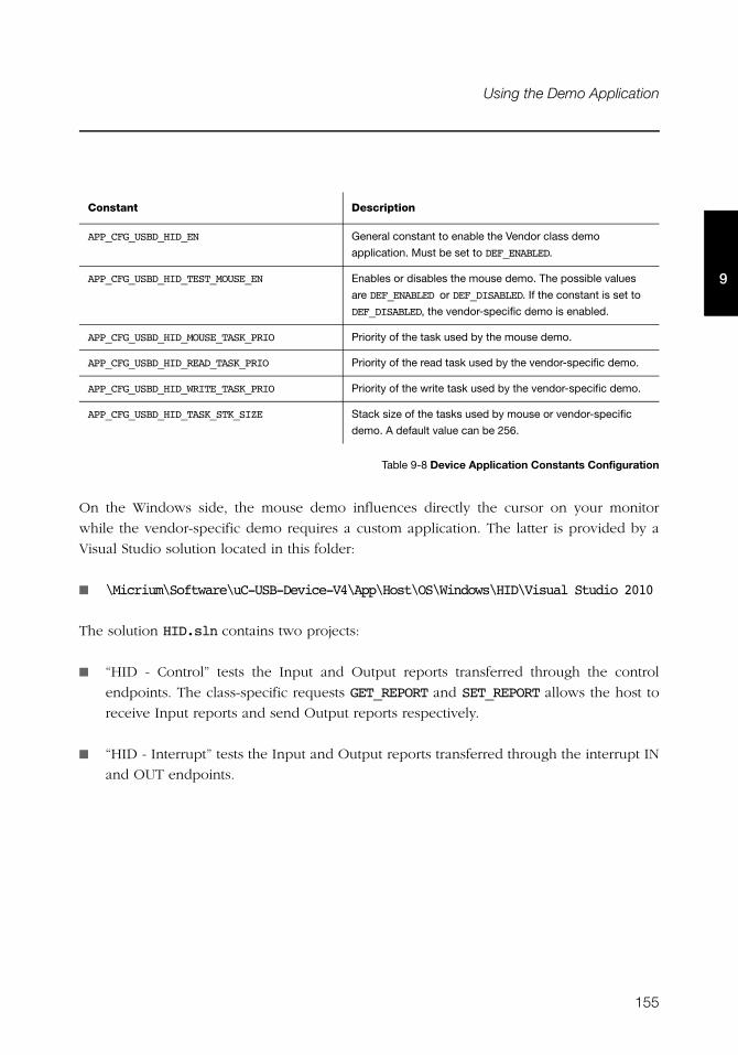
155
Using the Demo Application
9
Table 9-8 Device Application Constants Configuration
On the Windows side, the mouse demo influences directly the cursor on your monitor
while the vendor-specific demo requires a custom application. The latter is provided by a
Visual Studio solution located in this folder:
■ \Micrium\Software\uC-USB-Device-V4\App\Host\OS\Windows\HID\Visual Studio 2010
The solution HID.sln contains two projects:
■ “HID - Control” tests the Input and Output reports transferred through the control
endpoints. The class-specific requests GET_REPORT and SET_REPORT allows the host to
receive Input reports and send Output reports respectively.
■ “HID - Interrupt” tests the Input and Output reports transferred through the interrupt IN
and OUT endpoints.
Constant Description
APP_CFG_USBD_HID_EN General constant to enable the Vendor class demo
application. Must be set to DEF_ENABLED.
APP_CFG_USBD_HID_TEST_MOUSE_EN Enables or disables the mouse demo. The possible values
are DEF_ENABLED or DEF_DISABLED. If the constant is set to
DEF_DISABLED, the vendor-specific demo is enabled.
APP_CFG_USBD_HID_MOUSE_TASK_PRIO Priority of the task used by the mouse demo.
APP_CFG_USBD_HID_READ_TASK_PRIO Priority of the read task used by the vendor-specific demo.
APP_CFG_USBD_HID_WRITE_TASK_PRIO Priority of the write task used by the vendor-specific demo.
APP_CFG_USBD_HID_TASK_STK_SIZE Stack size of the tasks used by mouse or vendor-specific
demo. A default value can be 256.
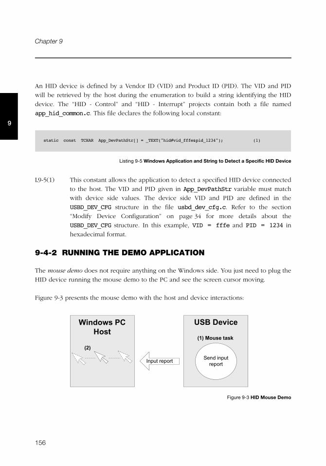
156
Chapter 9
9
An HID device is defined by a Vendor ID (VID) and Product ID (PID). The VID and PID
will be retrieved by the host during the enumeration to build a string identifying the HID
device. The “HID - Control” and “HID - Interrupt” projects contain both a file named
app_hid_common.c. This file declares the following local constant:
Listing 9-5 Windows Application and String to Detect a Specific HID Device
L9-5(1) This constant allows the application to detect a specified HID device connected
to the host. The VID and PID given in App_DevPathStr variable must match
with device side values. The device side VID and PID are defined in the
USBD_DEV_CFG structure in the file usbd_dev_cfg.c. Refer to the section
“Modify Device Configuration” on page 34 for more details about the
USBD_DEV_CFG structure. In this example, VID = fffe and PID = 1234 in
hexadecimal format.
9-4-2 RUNNING THE DEMO APPLICATION
The mouse demo does not require anything on the Windows side. You just need to plug the
HID device running the mouse demo to the PC and see the screen cursor moving.
Figure 9-3 presents the mouse demo with the host and device interactions:
Figure 9-3 HID Mouse Demo
static const TCHAR App_DevPathStr[] = _TEXT("hid#vid_fffe&pid_1234"); (1)
&'(�������
����������� ��� ������� ��� �
����1 )���� �/
+��, -��.��� ��
���
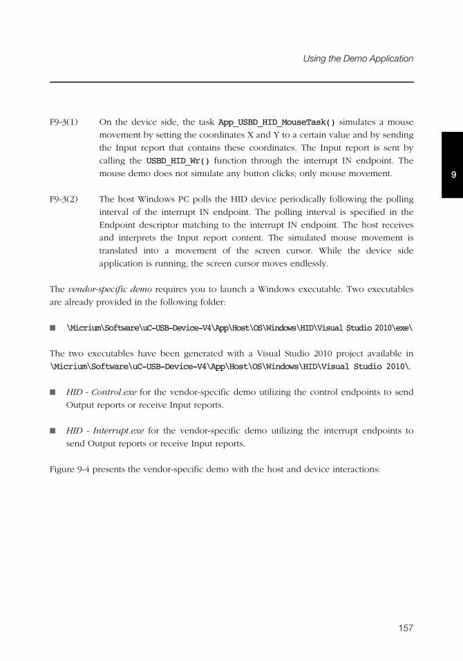
157
Using the Demo Application
9
F9-3(1) On the device side, the task App_USBD_HID_MouseTask() simulates a mouse
movement by setting the coordinates X and Y to a certain value and by sending
the Input report that contains these coordinates. The Input report is sent by
calling the USBD_HID_Wr() function through the interrupt IN endpoint. The
mouse demo does not simulate any button clicks; only mouse movement.
F9-3(2) The host Windows PC polls the HID device periodically following the polling
interval of the interrupt IN endpoint. The polling interval is specified in the
Endpoint descriptor matching to the interrupt IN endpoint. The host receives
and interprets the Input report content. The simulated mouse movement is
translated into a movement of the screen cursor. While the device side
application is running, the screen cursor moves endlessly.
The vendor-specific demo requires you to launch a Windows executable. Two executables
are already provided in the following folder:
■ \Micrium\Software\uC-USB-Device-V4\App\Host\OS\Windows\HID\Visual Studio 2010\exe\
The two executables have been generated with a Visual Studio 2010 project available in
\Micrium\Software\uC-USB-Device-V4\App\Host\OS\Windows\HID\Visual Studio 2010\.
■ HID - Control.exe for the vendor-specific demo utilizing the control endpoints to send
Output reports or receive Input reports.
■ HID - Interrupt.exe for the vendor-specific demo utilizing the interrupt endpoints to
send Output reports or receive Input reports.
Figure 9-4 presents the vendor-specific demo with the host and device interactions:
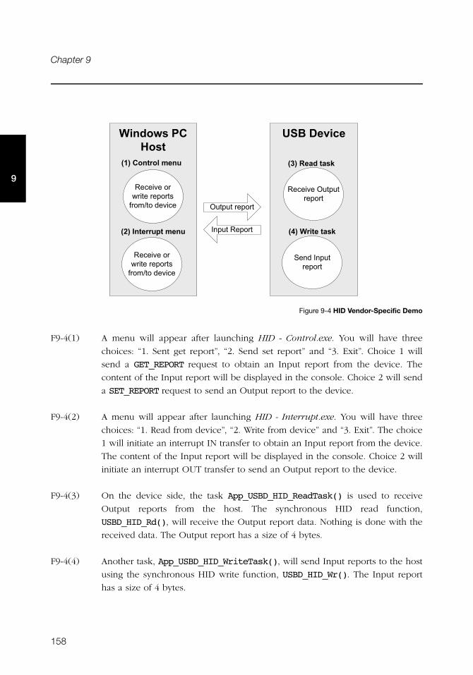
158
Chapter 9
9
Figure 9-4 HID Vendor-Specific Demo
F9-4(1) A menu will appear after launching HID - Control.exe. You will have three
choices: “1. Sent get report”, “2. Send set report” and “3. Exit”. Choice 1 will
send a GET_REPORT request to obtain an Input report from the device. The
content of the Input report will be displayed in the console. Choice 2 will send
a SET_REPORT request to send an Output report to the device.
F9-4(2) A menu will appear after launching HID - Interrupt.exe. You will have three
choices: “1. Read from device”, “2. Write from device” and “3. Exit”. The choice
1 will initiate an interrupt IN transfer to obtain an Input report from the device.
The content of the Input report will be displayed in the console. Choice 2 will
initiate an interrupt OUT transfer to send an Output report to the device.
F9-4(3) On the device side, the task App_USBD_HID_ReadTask() is used to receive
Output reports from the host. The synchronous HID read function,
USBD_HID_Rd(), will receive the Output report data. Nothing is done with the
received data. The Output report has a size of 4 bytes.
F9-4(4) Another task, App_USBD_HID_WriteTask(), will send Input reports to the host
using the synchronous HID write function, USBD_HID_Wr(). The Input report
has a size of 4 bytes.
&'(�������
�������+������ ��� �
����������� ��� �
+������ ��� �
��������� �
����0� ,�� �/
���+"����� �/
+��, -��.��� ��
�������� �C ���� ��� �!�% ��,���������
�������� �C ���� ��� �!�% ��,���������
����� ��" ��%��)
��������"")!��%��)
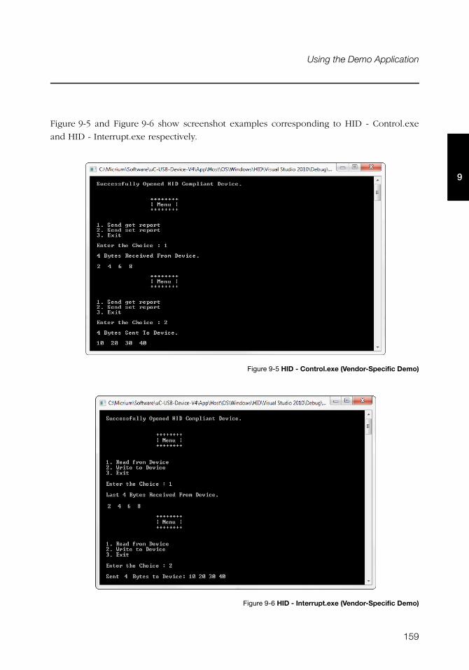
159
Using the Demo Application
9
Figure 9-5 and Figure 9-6 show screenshot examples corresponding to HID - Control.exe
and HID - Interrupt.exe respectively.
Figure 9-5 HID - Control.exe (Vendor-Specific Demo)
Figure 9-6 HID - Interrupt.exe (Vendor-Specific Demo)
160
Chapter 9
9
9-5 PORTING THE HID CLASS TO A RTOS
The HID class uses its own RTOS layer for different purposes:
■ A locking system is used to protect a given Input report. A host can get an Input report
by sending a GET_REPORT request to the device using the control endpoint or with an
interrupt IN transfer. GET_REPORT request processing is done by the device stack while
the interrupt IN transfer is done by the application. When the application executes the
interrupt IN transfer, the Input report data is stored internally. This report data stored
will be sent via a control transfer when GET_REPORT is received. The locking system
ensures the data integrity between the Input report data storage operation done within
an application task context and the GET_REPORT request processing done within the
device stack’s internal task context.
■ A locking system is used to protect the Output report processing between an
application task and the device stack’s internal task when the control endpoint is used.
The application provides to the HID class a receive buffer for the Output report in the
application task context. This receive buffer will be used by the device stack’s internal
task upon reception of a SET_REPORT request. The locking system ensures the receive
buffer and related variables integrity.
■ A locking system is used to protect the interrupt IN endpoint access from multiple
application tasks.
■ A synchronization mechanism is used to implement the blocking behavior of
USBD_HID_Rd() when the control endpoint is used.
■ A synchronization mechanism is used to implement the blocking behavior of
USBD_HID_Wr() because the HID class internally uses the asynchronous interrupt API
for HID write.
■ A task is used to process periodic Input reports. Refer to section 9-6 “Periodic Input
Reports Task” on page 161 for more details about this task.
By default, Micriμm will provide an RTOS layer for both μC/OS-II and μC/OS-III. However,
it is possible to create your own RTOS layer. Your layer will need to implement the
functions listed in Table 9-9. For a complete API description, refer to Appendix D, “HID API
Reference” on page 387.
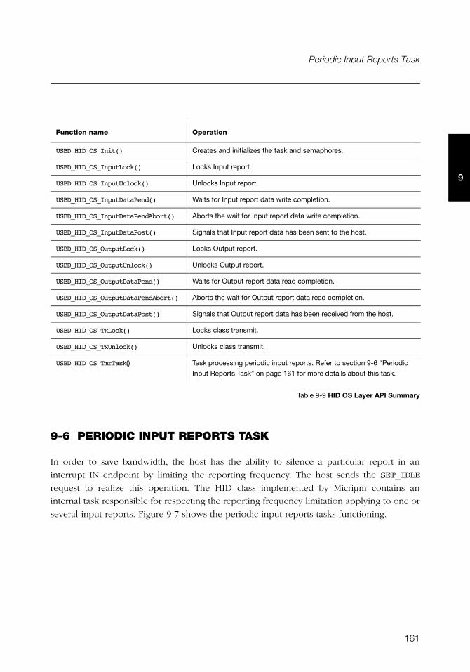
161
Periodic Input Reports Task
9
Table 9-9 HID OS Layer API Summary
9-6 PERIODIC INPUT REPORTS TASK
In order to save bandwidth, the host has the ability to silence a particular report in an
interrupt IN endpoint by limiting the reporting frequency. The host sends the SET_IDLE
request to realize this operation. The HID class implemented by Micriμm contains an
internal task responsible for respecting the reporting frequency limitation applying to one or
several input reports. Figure 9-7 shows the periodic input reports tasks functioning.
Function name Operation
USBD_HID_OS_Init() Creates and initializes the task and semaphores.
USBD_HID_OS_InputLock() Locks Input report.
USBD_HID_OS_InputUnlock() Unlocks Input report.
USBD_HID_OS_InputDataPend() Waits for Input report data write completion.
USBD_HID_OS_InputDataPendAbort() Aborts the wait for Input report data write completion.
USBD_HID_OS_InputDataPost() Signals that Input report data has been sent to the host.
USBD_HID_OS_OutputLock() Locks Output report.
USBD_HID_OS_OutputUnlock() Unlocks Output report.
USBD_HID_OS_OutputDataPend() Waits for Output report data read completion.
USBD_HID_OS_OutputDataPendAbort() Aborts the wait for Output report data read completion.
USBD_HID_OS_OutputDataPost() Signals that Output report data has been received from the host.
USBD_HID_OS_TxLock() Locks class transmit.
USBD_HID_OS_TxUnlock() Unlocks class transmit.
USBD_HID_OS_TmrTask() Task processing periodic input reports. Refer to section 9-6 “Periodic
Input Reports Task” on page 161 for more details about this task.
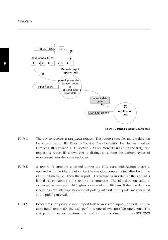
162
Chapter 9
9
Figure 9-7 Periodic Input Reports Task
F9-7(1) The device receives a SET_IDLE request. This request specifies an idle duration
for a given report ID. Refer to “Device Class Definition for Human Interface
Devices (HID) Version 1.11”, section 7.2.4 for more details about the SET_IDLE
request. A report ID allows you to distinguish among the different types of
reports sent over the same endpoint.
F9-7(2) A report ID structure allocated during the HID class initialization phase is
updated with the idle duration. An idle duration counter is initialized with the
idle duration value. Then the report ID structure is inserted at the end of a
linked list containing input reports ID structures. The idle duration value is
expressed in 4-ms unit which gives a range of 4 to 1020 ms. If the idle duration
is less than the interrupt IN endpoint polling interval, the reports are generated
at the polling interval.
F9-7(3) Every 4 ms, the periodic input report task browses the input reports ID list. For
each input report ID, the task performs one of two possible operations. The
task period matches the 4-ms unit used for the idle duration. If no SET_IDLE
0 / ; B
������ ��� �!������!�
D������ ���?�
����������������� ������������
� ���������������� ��� ������
.�"� ,�����!)��"�! "���� �/
��������� �
���
���
2!!��� �� ��� �/*�C���������� �
���� ���������#�%%�
���
163
Periodic Input Reports Task
9
requests have been sent by the host, the input reports ID list is empty and the
task has nothing to process. The task processes only report IDs different from 0
and with an idle duration greater than 0.
F9-7(4) For a given input report ID, the task verifies if the idle duration has elapsed. If
the idle duration has not elapsed, the counter is decremented and no input
report is sent to the host.
F9-7(5) If the idle duration has elapsed, that is the idle duration counter has reached
zero, an input report is sent to the host by calling the USBD_HID_Wr() function
via the interrupt IN endpoint.
F9-7(6) The input report data sent by the task comes from an internal data buffer
allocated for each input report described in the Report descriptor. An
application task can call the USBD_HID_Wr() function to send an input report.
After sending the input report data, USBD_HID_Wr() updates the internal buffer
associated to an input report ID with the data just sent. Then, the periodic
input reports task always sends the same input report data after each idle
duration elapsed and until the application task updates the data in the internal
buffer. There is some locking mechanism to avoid corruption of the input
report ID data in the event of a modification happening at the exact time of
transmission done by the periodic input report task.
The periodic input reports task is implemented in the HID OS layer in the function
USBD_HID_OS_TmrTask(). Refer to section D-2 “HID OS Functions” on page 402 for more
details about this function.

164
Chapter 9
9
165
Chapter
10Mass Storage Class
This section describes the mass storage device class (MSC) supported by μC/USB-Device.
The MSC implementation offered by μC/USB-Device is in compliance with the following
specifications:
■ Universal Serial Bus Mass Storage Class Specification Overview, Revision 1.3 Sept. 5, 2008.
■ Universal Serial Bus Mass Storage Class Bulk-Only Transport, Revision 1.0 Sept. 31, 1999.
MSC is a protocol that enables the transfer of information between a USB device and a host.
The information is anything that can be stored electronically: executable programs, source
code, documents, images, configuration data, or other text or numeric data. The USB device
appears as an external storage medium to the host, enabling the transfer of files via drag
and drop.
A file system defines how the files are organized in the storage media. The USB mass
storage class specification does not require any particular file system to be used on
conforming devices. Instead, it provides a simple interface to read and write sectors of data
using the Small Computer System Interface (SCSI) transparent command set. As such,
operating systems may treat the USB drive like a hard drive and can format it with any file
system they like.
The USB mass storage device class supports two transport protocols:
■ Bulk-Only Transport (BOT)
■ Control/Bulk/Interrupt (CBI) Transport.
The mass storage device class supported by μC/USB-Device implements the SCSI
transparent command set using the BOT protocol only, which signifies that only bulk
endpoints will be used to transmit data and status information.
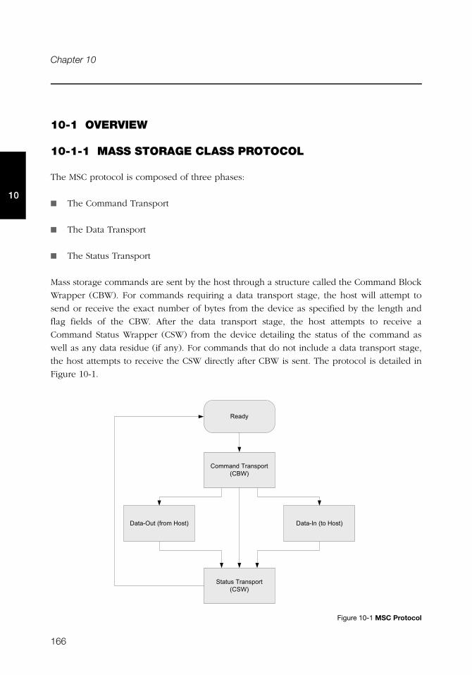
166
Chapter 10
10
10-1 OVERVIEW
10-1-1 MASS STORAGE CLASS PROTOCOL
The MSC protocol is composed of three phases:
■ The Command Transport
■ The Data Transport
■ The Status Transport
Mass storage commands are sent by the host through a structure called the Command Block
Wrapper (CBW). For commands requiring a data transport stage, the host will attempt to
send or receive the exact number of bytes from the device as specified by the length and
flag fields of the CBW. After the data transport stage, the host attempts to receive a
Command Status Wrapper (CSW) from the device detailing the status of the command as
well as any data residue (if any). For commands that do not include a data transport stage,
the host attempts to receive the CSW directly after CBW is sent. The protocol is detailed in
Figure 10-1.
Figure 10-1 MSC Protocol
4 �%5
+���� %#��� '����#�+!6�
����,��#�����#)�'�� ����,� #���#)�'��
����'#��� '����#�+�6�
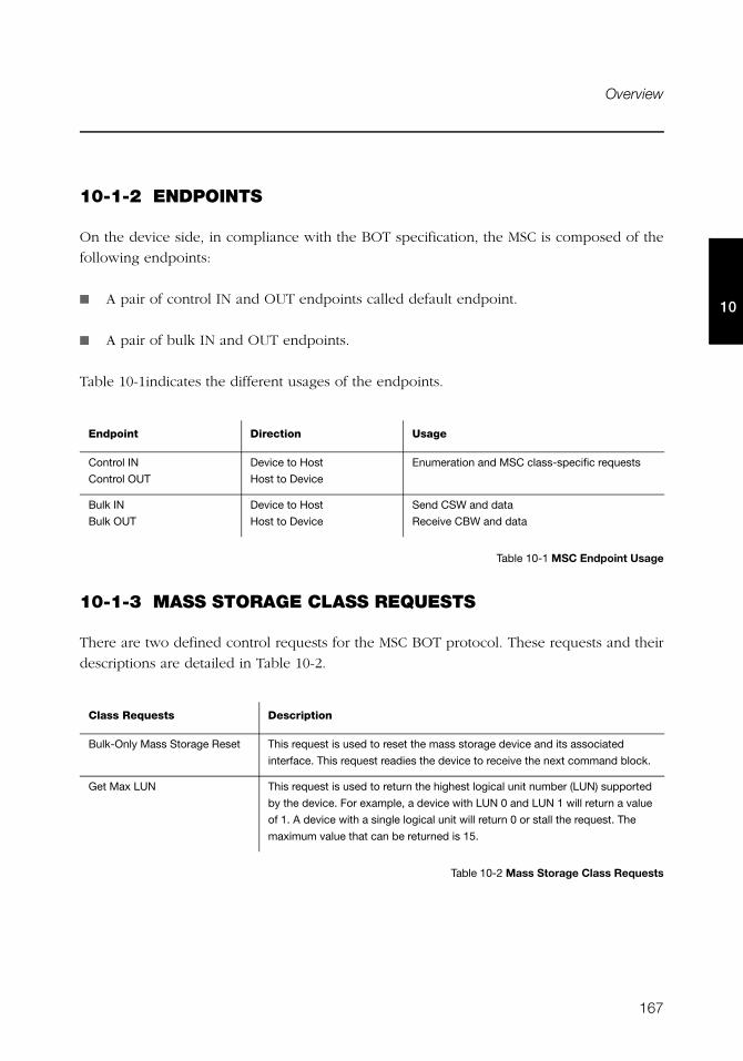
167
Overview
10
10-1-2 ENDPOINTS
On the device side, in compliance with the BOT specification, the MSC is composed of the
following endpoints:
■ A pair of control IN and OUT endpoints called default endpoint.
■ A pair of bulk IN and OUT endpoints.
Table 10-1indicates the different usages of the endpoints.
Table 10-1 MSC Endpoint Usage
10-1-3 MASS STORAGE CLASS REQUESTS
There are two defined control requests for the MSC BOT protocol. These requests and their
descriptions are detailed in Table 10-2.
Table 10-2 Mass Storage Class Requests
Endpoint Direction Usage
Control IN
Control OUT
Device to Host
Host to Device
Enumeration and MSC class-specific requests
Bulk IN
Bulk OUT
Device to Host
Host to Device
Send CSW and data
Receive CBW and data
Class Requests Description
Bulk-Only Mass Storage Reset This request is used to reset the mass storage device and its associated
interface. This request readies the device to receive the next command block.
Get Max LUN This request is used to return the highest logical unit number (LUN) supported
by the device. For example, a device with LUN 0 and LUN 1 will return a value
of 1. A device with a single logical unit will return 0 or stall the request. The
maximum value that can be returned is 15.
168
Chapter 10
10
10-1-4 SMALL COMPUTER SYSTEM INTERFACE (SCSI)
SCSI is a set of standards for handling communication between computers and peripheral
devices. These standards include commands, protocols, electrical interfaces and optical
interfaces. Storage devices that use other hardware interfaces such as USB, use SCSI
commands for obtaining device/host information and controlling the device’s operation and
transferring blocks of data in the storage media.
SCSI commands cover a vast range of device types and functions and as such, devices need
a subset of these commands. In general, the following commands are necessary for basic
communication:
■ INQUIRY
■ READ CAPACITY (10)
■ READ(10)
■ REQUEST SENSE
■ TEST UNIT READY
■ WRITE(10)
Refer to Table 10-3 to see the full list of implemented SCSI commands by μC/USB-Device.
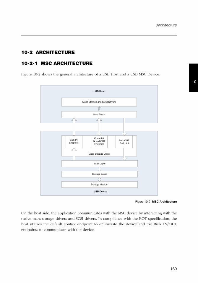
169
Architecture
10
10-2 ARCHITECTURE
10-2-1 MSC ARCHITECTURE
Figure 10-2 shows the general architecture of a USB Host and a USB MSC Device.
Figure 10-2 MSC Architecture
On the host side, the application communicates with the MSC device by interacting with the
native mass storage drivers and SCSI drivers. In compliance with the BOT specification, the
host utilizes the default control endpoint to enumerate the device and the Bulk IN/OUT
endpoints to communicate with the device.
����������
��������
)�'�#����1
�''#�����& #� %#�+��#���$ �'
�''#�����& #+��''
!�1#��#� %��� �
!�1#���#� %��� �
�+��#-�5 �
�����& #-�5 �
�����& # %��
+� ����#���#� %#���� %��� �
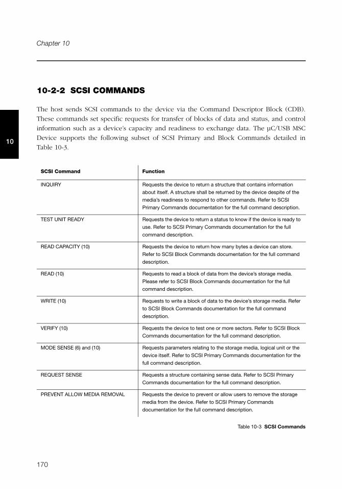
170
Chapter 10
10
10-2-2 SCSI COMMANDS
The host sends SCSI commands to the device via the Command Descriptor Block (CDB).
These commands set specific requests for transfer of blocks of data and status, and control
information such as a device’s capacity and readiness to exchange data. The μC/USB MSC
Device supports the following subset of SCSI Primary and Block Commands detailed in
Table 10-3.
Table 10-3 SCSI Commands
SCSI Command Function
INQUIRY Requests the device to return a structure that contains information
about itself. A structure shall be returned by the device despite of the
media’s readiness to respond to other commands. Refer to SCSI
Primary Commands documentation for the full command description.
TEST UNIT READY Requests the device to return a status to know if the device is ready to
use. Refer to SCSI Primary Commands documentation for the full
command description.
READ CAPACITY (10) Requests the device to return how many bytes a device can store.
Refer to SCSI Block Commands documentation for the full command
description.
READ (10) Requests to read a block of data from the device’s storage media.
Please refer to SCSI Block Commands documentation for the full
command description.
WRITE (10) Requests to write a block of data to the device’s storage media. Refer
to SCSI Block Commands documentation for the full command
description.
VERIFY (10) Requests the device to test one or more sectors. Refer to SCSI Block
Commands documentation for the full command description.
MODE SENSE (6) and (10) Requests parameters relating to the storage media, logical unit or the
device itself. Refer to SCSI Primary Commands documentation for the
full command description.
REQUEST SENSE Requests a structure containing sense data. Refer to SCSI Primary
Commands documentation for the full command description.
PREVENT ALLOW MEDIA REMOVAL Requests the device to prevent or allow users to remove the storage
media from the device. Refer to SCSI Primary Commands
documentation for the full command description.
171
RTOS Layer
10
10-2-3 STORAGE LAYER AND STORAGE MEDIUM
The storage layer is the interface between the μC/USB MSC Device and the file system
storage medium. The storage layer is responsible of initializing, reading and writing to the
storage medium as well as obtaining information regarding its capacity and status. By
default, Micriμm will provide a storage layer implementation (named RAMDisk) by utilizing
the hardware’s platform memory as storage medium. Aside from this implementation, you
have the option to use Micriμm’s μC/FS or even utilize a file system storage medium of your
own. In the event you use a file system storage medium of your own, you will need to
create a storage layer port to communicate your storage medium to the μC/USB MSC
Device. Please refer to section 10-6 “Porting MSC to a Storage Layer” on page 180 to learn
how to implement this storage layer.
10-3 RTOS LAYER
MSC device communication relies on a task handler that implements the MSC protocol. This
task handler needs to be notified when the device is properly enumerated before
communication begins. Once communication begins, the task must also keep track of
endpoint update statuses to correctly implement the MSC protocol. These types of
notification are handled by RTOS signals. For the MSC RTOS layer, there are two
semaphores created. One for enumeration process and one for communication process. By
default, Micriμm will provide RTOS layers for both μC/OS-II and μC/OS-III. However, it is
also possible to create your own RTOS layer. Please refer to section 10-7 “Porting MSC to a
RTOS” on page 181 to learn how to port to a different RTOS.
10-3-1 MASS STORAGE TASK HANDLER
The MSC task handler implements the MSC protocol, responsible for the communication
between the device and the host. The task handler is initialized when USBD_MSC_Init()
is called. The MSC protocol is handled by a state machine comprised of 9 states. The
transition between these states are detailed in Figure 10-3.
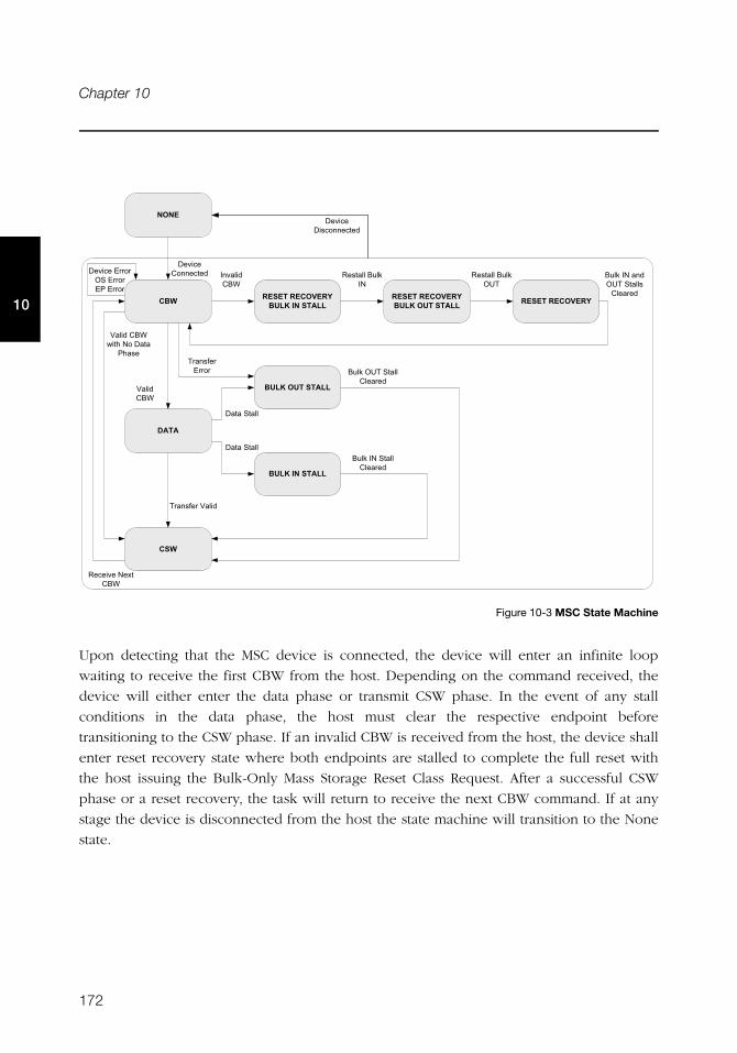
172
Chapter 10
10
Figure 10-3 MSC State Machine
Upon detecting that the MSC device is connected, the device will enter an infinite loop
waiting to receive the first CBW from the host. Depending on the command received, the
device will either enter the data phase or transmit CSW phase. In the event of any stall
conditions in the data phase, the host must clear the respective endpoint before
transitioning to the CSW phase. If an invalid CBW is received from the host, the device shall
enter reset recovery state where both endpoints are stalled to complete the full reset with
the host issuing the Bulk-Only Mass Storage Reset Class Request. After a successful CSW
phase or a reset recovery, the task will return to receive the next CBW command. If at any
stage the device is disconnected from the host the state machine will transition to the None
state.
-+�+.�-+�)1+-2��'3�*4��.,''��5 -+�+.�-+�)1+-2-+�+.�-+�)1+-2
��'3�)�.��.,''
�,.,
��'3�*4��.,''
��'3�)�.��.,''
��5
� $���%#+!6
3���%#+!6
4 '����#!�1#��
4 '����#!�1#���
!�1#��#� %#���#�����'#+� �� %
� $�� #�������#�������#�����
!�1#��#�����#+� �� %
!�1#���#�����#+� �� %
4 � �$ #� ��#+!6
��� '� �#3���%
4)4+
� $�� #+� �� %
����#�����
����#�����
3���%#+!6#���0#��#����#
�0�'
� $�� #��'�� �� %
��� '� �#�����
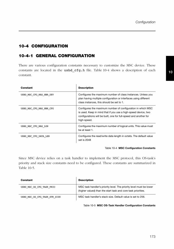
173
Configuration
10
10-4 CONFIGURATION
10-4-1 GENERAL CONFIGURATION
There are various configuration constants necessary to customize the MSC device. These
constants are located in the usbd_cfg.h file. Table 10-4 shows a description of each
constant.
Table 10-4 MSC Configuration Constants
Since MSC device relies on a task handler to implement the MSC protocol, this OS-task’s
priority and stack size constants need to be configured. These constants are summarized in
Table 10-5.
Table 10-5 MSC OS-Task Handler Configuration Constants
Constant Description
USBD_MSC_CFG_MAX_NBR_DEV Configures the maximum number of class instances. Unless you
plan having multiple configuration or interfaces using different
class instances, this should be set to 1.
USBD_MSC_CFG_MAX_NBR_CFG Configures the maximum number of configuration in which MSC
is used. Keep in mind that if you use a high-speed device, two
configurations will be built, one for full-speed and another for
high-speed.
USBD_MSC_CFG_MAX_LUN Configures the maximum number of logical units. This value must
be at least 1.
USBD_MSC_CFG_DATA_LEN Configures the read/write data length in octets. The default value
set is 2048
Constant Description
USBD_MSC_OS_CFG_TASK_PRIO MSC task handler’s priority level. The priority level must be lower
(higher valued) than the start task and core task priorities.
USBD_MSC_OS_CFG_TASK_STK_SIZE MSC task handler’s stack size. Default value is set to 256.
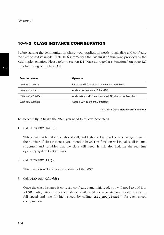
174
Chapter 10
10
10-4-2 CLASS INSTANCE CONFIGURATION
Before starting the communication phase, your application needs to initialize and configure
the class to suit its needs. Table 10-6 summarizes the initialization functions provided by the
MSC implementation. Please refer to section E-1 “Mass Storage Class Functions” on page 420
for a full listing of the MSC API.
.
Table 10-6 Class Instance API Functions
To successfully initialize the MSC, you need to follow these steps:
1 Call USBD_MSC_Init()
This is the first function you should call, and it should be called only once regardless of
the number of class instances you intend to have. This function will initialize all internal
structures and variables that the class will need. It will also initialize the real-time
operating system (RTOS) layer.
2 Call USBD_MSC_Add()
This function will add a new instance of the MSC.
3 Call USBD_MSC_CfgAdd()
Once the class instance is correctly configured and initialized, you will need to add it to
a USB configuration. High speed devices will build two separate configurations, one for
full speed and one for high speed by calling USBD_MSC_CfgAdd() for each speed
configuration.
Function name Operation
USBD_MSC_Init() Initializes MSC internal structures and variables.
USBD_MSC_Add() Adds a new instance of the MSC.
USBD_MSC_CfgAdd() Adds existing MSC instance into USB device configuration.
USBD_MSC_LunAdd() Adds a LUN to the MSC interface.

175
Configuration
10
4 Call USBD_MSC_LunAdd()
Lastly, you add a logical unit to the MSC interface by calling this function. You will
specify the type and volume of the logical unit you want to add as well as device details
such as vendor ID, product ID, product revision level and read only. Logical units are
added by a device driver string name composed of the storage device driver name and
the logical unit number as follows: <device_driver_name>:<logical_unit_number>:.
The logical unit number starts counting from number 0. For example, if a device has
only one logical unit, the <logical_unit_number> specified in this field should be 0.
Listing 10-1 shows how the latter functions are called during MSC initialization.
USBD_ERR err;
CPU_INT08U msc_nbr;
CPU_BOOLEAN valid;
USBD_MSC_Init(&err); (1)
if (err != USBD_ERR_NONE){
return (DEF_FAIL);
}
msc_nbr = USBD_MSC_Add(&err); (2)
if (cfg_hs != USBD_CFG_NBR_NONE){
valid = USBD_MSC_CfgAdd (msc_nbr, (3)
dev_nbr,
cfg_hs,
&err);
if (valid != DEF_YES) {
return (DEF_FAIL);
}
}
if (cfg_fs != USBD_CFG_NBR_NONE){
valid = USBD_MSC_CfgAdd (msc_nbr, (4)
dev_nbr,
cfg_fs,
&err);
if (valid != DEF_YES) {
return (DEF_FAIL);
}
}
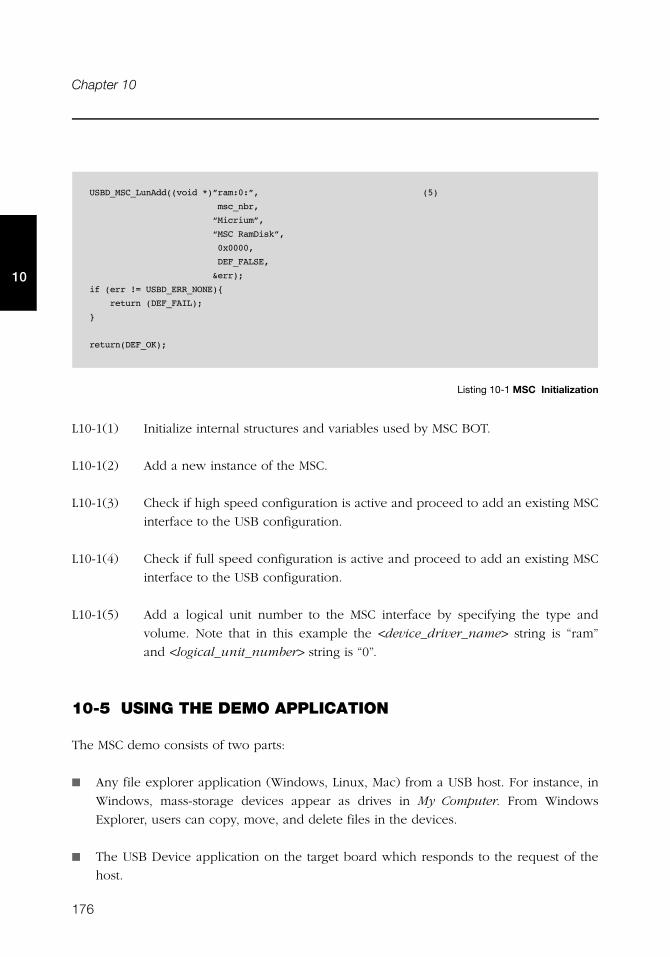
176
Chapter 10
10
Listing 10-1 MSC Initialization
L10-1(1) Initialize internal structures and variables used by MSC BOT.
L10-1(2) Add a new instance of the MSC.
L10-1(3) Check if high speed configuration is active and proceed to add an existing MSC
interface to the USB configuration.
L10-1(4) Check if full speed configuration is active and proceed to add an existing MSC
interface to the USB configuration.
L10-1(5) Add a logical unit number to the MSC interface by specifying the type and
volume. Note that in this example the <device_driver_name> string is “ram”
and <logical_unit_number> string is “0”.
10-5 USING THE DEMO APPLICATION
The MSC demo consists of two parts:
■ Any file explorer application (Windows, Linux, Mac) from a USB host. For instance, in
Windows, mass-storage devices appear as drives in My Computer. From Windows
Explorer, users can copy, move, and delete files in the devices.
■ The USB Device application on the target board which responds to the request of the
host.
USBD_MSC_LunAdd((void *)”ram:0:”, (5)
msc_nbr,
“Micrium”,
“MSC RamDisk”,
0x0000,
DEF_FALSE,
&err);
if (err != USBD_ERR_NONE){
return (DEF_FAIL);
}
return(DEF_OK);
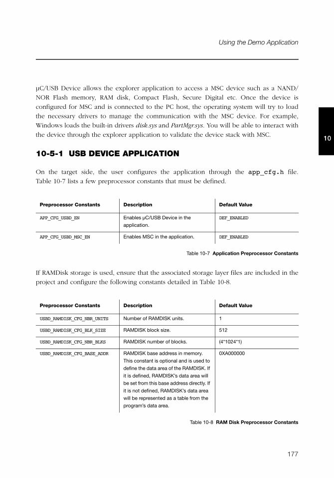
177
Using the Demo Application
10
μC/USB Device allows the explorer application to access a MSC device such as a NAND/
NOR Flash memory, RAM disk, Compact Flash, Secure Digital etc. Once the device is
configured for MSC and is connected to the PC host, the operating system will try to load
the necessary drivers to manage the communication with the MSC device. For example,
Windows loads the built-in drivers disk.sys and PartMgr.sys. You will be able to interact with
the device through the explorer application to validate the device stack with MSC.
10-5-1 USB DEVICE APPLICATION
On the target side, the user configures the application through the app_cfg.h file.
Table 10-7 lists a few preprocessor constants that must be defined.
Table 10-7 Application Preprocessor Constants
If RAMDisk storage is used, ensure that the associated storage layer files are included in the
project and configure the following constants detailed in Table 10-8.
Table 10-8 RAM Disk Preprocessor Constants
Preprocessor Constants Description Default Value
APP_CFG_USBD_EN Enables μC/USB Device in the
application.
DEF_ENABLED
APP_CFG_USBD_MSC_EN Enables MSC in the application. DEF_ENABLED
Preprocessor Constants Description Default Value
USBD_RAMDISK_CFG_NBR_UNITS Number of RAMDISK units. 1
USBD_RAMDISK_CFG_BLK_SIZE RAMDISK block size. 512
USBD_RAMDISK_CFG_NBR_BLKS RAMDISK number of blocks. (4*1024*1)
USBD_RAMDISK_CFG_BASE_ADDR RAMDISK base address in memory.
This constant is optional and is used to
define the data area of the RAMDISK. If
it is defined, RAMDISK’s data area will
be set from this base address directly. If
it is not defined, RAMDISK’s data area
will be represented as a table from the
program’s data area.
0XA000000
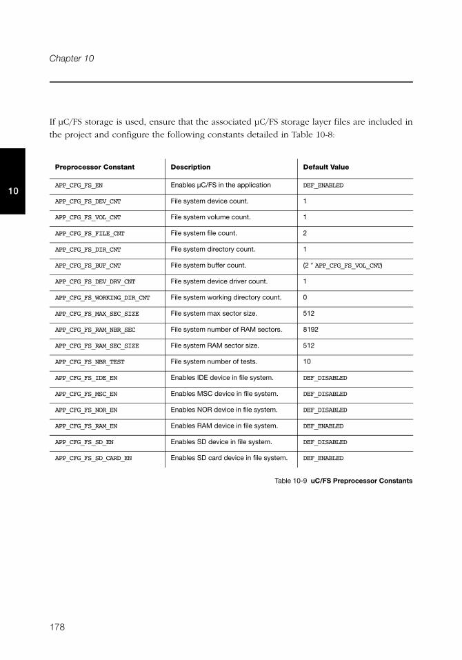
178
Chapter 10
10
If μC/FS storage is used, ensure that the associated μC/FS storage layer files are included in
the project and configure the following constants detailed in Table 10-8:
Table 10-9 uC/FS Preprocessor Constants
Preprocessor Constant Description Default Value
APP_CFG_FS_EN Enables μC/FS in the application DEF_ENABLED
APP_CFG_FS_DEV_CNT File system device count. 1
APP_CFG_FS_VOL_CNT File system volume count. 1
APP_CFG_FS_FILE_CNT File system file count. 2
APP_CFG_FS_DIR_CNT File system directory count. 1
APP_CFG_FS_BUF_CNT File system buffer count. (2 * APP_CFG_FS_VOL_CNT)
APP_CFG_FS_DEV_DRV_CNT File system device driver count. 1
APP_CFG_FS_WORKING_DIR_CNT File system working directory count. 0
APP_CFG_FS_MAX_SEC_SIZE File system max sector size. 512
APP_CFG_FS_RAM_NBR_SEC File system number of RAM sectors. 8192
APP_CFG_FS_RAM_SEC_SIZE File system RAM sector size. 512
APP_CFG_FS_NBR_TEST File system number of tests. 10
APP_CFG_FS_IDE_EN Enables IDE device in file system. DEF_DISABLED
APP_CFG_FS_MSC_EN Enables MSC device in file system. DEF_DISABLED
APP_CFG_FS_NOR_EN Enables NOR device in file system. DEF_DISABLED
APP_CFG_FS_RAM_EN Enables RAM device in file system. DEF_ENABLED
APP_CFG_FS_SD_EN Enables SD device in file system. DEF_DISABLED
APP_CFG_FS_SD_CARD_EN Enables SD card device in file system. DEF_ENABLED
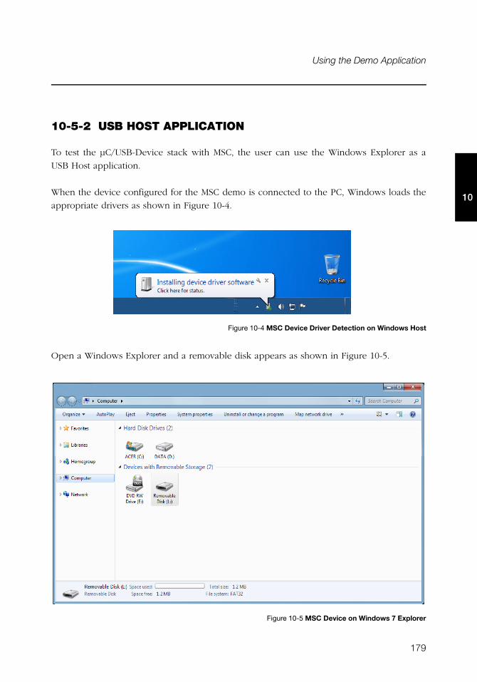
179
Using the Demo Application
10
10-5-2 USB HOST APPLICATION
To test the μC/USB-Device stack with MSC, the user can use the Windows Explorer as a
USB Host application.
When the device configured for the MSC demo is connected to the PC, Windows loads the
appropriate drivers as shown in Figure 10-4.
Figure 10-4 MSC Device Driver Detection on Windows Host
Open a Windows Explorer and a removable disk appears as shown in Figure 10-5.
Figure 10-5 MSC Device on Windows 7 Explorer
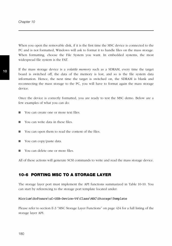
180
Chapter 10
10
When you open the removable disk, if it is the first time the MSC device is connected to the
PC and is not formatted, Windows will ask to format it to handle files on the mass storage.
When formatting, choose the File System you want. In embedded systems, the most
widespread file system is the FAT.
If the mass storage device is a volatile memory such as a SDRAM, every time the target
board is switched off, the data of the memory is lost, and so is the file system data
information. Hence, the next time the target is switched on, the SDRAM is blank and
reconnecting the mass storage to the PC, you will have to format again the mass storage
device.
Once the device is correctly formatted, you are ready to test the MSC demo. Below are a
few examples of what you can do:
■ You can create one or more text files.
■ You can write data in these files.
■ You can open them to read the content of the files.
■ You can copy/paste data.
■ You can delete one or more files.
All of these actions will generate SCSI commands to write and read the mass storage device.
10-6 PORTING MSC TO A STORAGE LAYER
The storage layer port must implement the API functions summarized in Table 10-10. You
can start by referencing to the storage port template located under:
Micrium\Software\uC-USB-Device-V4\Class\MSC\Storage\Template
Please refer to section E-3 “MSC Storage Layer Functions” on page 434 for a full listing of the
storage layer API.
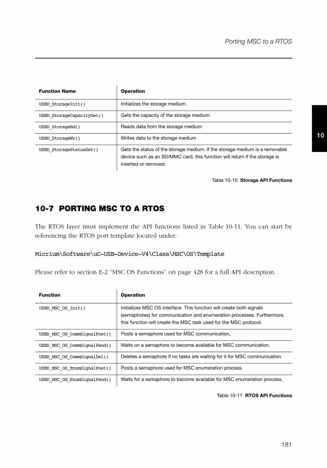
181
Porting MSC to a RTOS
10
Table 10-10 Storage API Functions
10-7 PORTING MSC TO A RTOS
The RTOS layer must implement the API functions listed in Table 10-11. You can start by
referencing the RTOS port template located under:
Micrium\Software\uC-USB-Device-V4\Class\MSC\OS\Template
Please refer to section E-2 “MSC OS Functions” on page 428 for a full API description.
Table 10-11 RTOS API Functions
Function Name Operation
USBD_StorageInit() Initializes the storage medium.
USBD_StorageCapacityGet() Gets the capacity of the storage medium
USBD_StorageRd() Reads data from the storage medium
USBD_StorageWr() Writes data to the storage medium
USBD_StorageStatusGet() Gets the status of the storage medium. If the storage medium is a removable
device such as an SD/MMC card, this function will return if the storage is
inserted or removed.
Function Operation
USBD_MSC_OS_Init() Initializes MSC OS interface. This function will create both signals
(semaphores) for communication and enumeration processes. Furthermore,
this function will create the MSC task used for the MSC protocol.
USBD_MSC_OS_CommSignalPost() Posts a semaphore used for MSC communication,
USBD_MSC_OS_CommSignalPend() Waits on a semaphore to become available for MSC communication.
USBD_MSC_OS_CommSignalDel() Deletes a semaphore if no tasks are waiting for it for MSC communication.
USBD_MSC_OS_EnumSignalPost() Posts a semaphore used for MSC enumeration process.
USBD_MSC_OS_EnumSignalPend() Waits for a semaphore to become available for MSC enumeration process.

182
Chapter 10
10
183
Chapter
11Personal Healthcare Device Class
This section describes the Personal Healthcare Device Class (PHDC) supported by
μC/USB-Device. The implementation offered refers to the following USB-IF specification:
■ USB Device Class Definition for Personal Healthcare Devices, release 1.0, Nov. 8 2007.
PHDC allows you to build USB devices that are meant to be used to monitor and improve
personal healthcare. Lots of modern personal healthcare devices have arrived on the market
in recent years. Glucose meter, pulse oximeter and blood-pressure monitor are some
examples. A characteristic of these devices is that they can be connected to a computer for
playback, live monitoring or configuration. One of the typical ways to connect these devices
to a computer is by using a USB connection, and that’s why PHDC has been developed.
Although PHDC is a standard, most modern Operating Systems (OS) do not provide any
specific driver for this class. When working with Microsoft Windows®, developers can use
the WinUsb driver provided by Microsoft to create their own driver. The Continua Health
Alliance also provides an example of a PHDC driver based on libusb (an open source USB
library, for more information, see http://www.libusb.org/). This example driver is part of
the Vendor Assisted Source-Code (VASC).
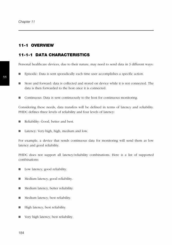
184
Chapter 11
11
11-1 OVERVIEW
11-1-1 DATA CHARACTERISTICS
Personal healthcare devices, due to their nature, may need to send data in 3 different ways:
■ Episodic: Data is sent sporadically each time user accomplishes a specific action.
■ Store and forward: data is collected and stored on device while it is not connected. The
data is then forwarded to the host once it is connected.
■ Continuous: Data is sent continuously to the host for continuous monitoring.
Considering these needs, data transfers will be defined in terms of latency and reliability.
PHDC defines three levels of reliability and four levels of latency:
■ Reliability: Good, better and best.
■ Latency: Very-high, high, medium and low.
For example, a device that sends continuous data for monitoring will send them as low
latency and good reliability.
PHDC does not support all latency/reliability combinations. Here is a list of supported
combinations:
■ Low latency, good reliability.
■ Medium latency, good reliability.
■ Medium latency, better reliability.
■ Medium latency, best reliability.
■ High latency, best reliability.
■ Very high latency, best reliability.
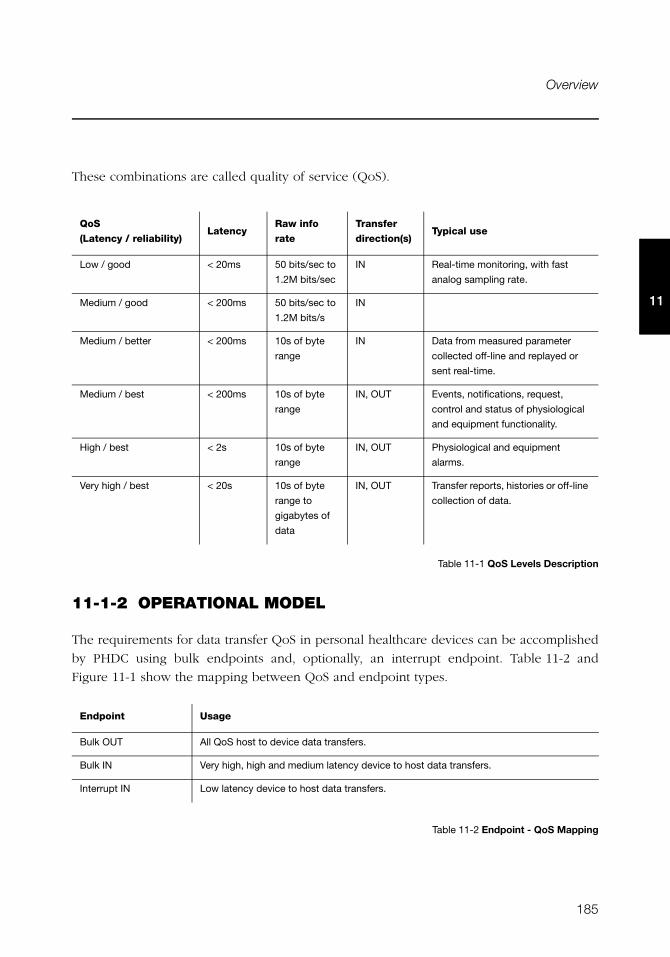
185
Overview
11
These combinations are called quality of service (QoS).
Table 11-1 QoS Levels Description
11-1-2 OPERATIONAL MODEL
The requirements for data transfer QoS in personal healthcare devices can be accomplished
by PHDC using bulk endpoints and, optionally, an interrupt endpoint. Table 11-2 and
Figure 11-1 show the mapping between QoS and endpoint types.
Table 11-2 Endpoint - QoS Mapping
QoS
(Latency / reliability)Latency
Raw info
rate
Transfer
direction(s)Typical use
Low / good < 20ms 50 bits/sec to
1.2M bits/sec
IN Real-time monitoring, with fast
analog sampling rate.
Medium / good < 200ms 50 bits/sec to
1.2M bits/s
IN
Medium / better < 200ms 10s of byte
range
IN Data from measured parameter
collected off-line and replayed or
sent real-time.
Medium / best < 200ms 10s of byte
range
IN, OUT Events, notifications, request,
control and status of physiological
and equipment functionality.
High / best < 2s 10s of byte
range
IN, OUT Physiological and equipment
alarms.
Very high / best < 20s 10s of byte
range to
gigabytes of
data
IN, OUT Transfer reports, histories or off-line
collection of data.
Endpoint Usage
Bulk OUT All QoS host to device data transfers.
Bulk IN Very high, high and medium latency device to host data transfers.
Interrupt IN Low latency device to host data transfers.
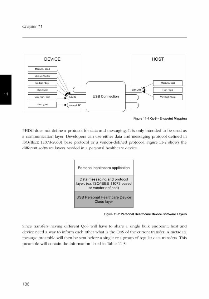
186
Chapter 11
11
Figure 11-1 QoS - Endpoint Mapping
PHDC does not define a protocol for data and messaging. It is only intended to be used as
a communication layer. Developers can use either data and messaging protocol defined in
ISO/IEEE 11073-20601 base protocol or a vendor-defined protocol. Figure 11-2 shows the
different software layers needed in a personal healthcare device.
Figure 11-2 Personal Healthcare Device Software Layers
Since transfers having different QoS will have to share a single bulk endpoint, host and
device need a way to inform each other what is the QoS of the current transfer. A metadata
message preamble will then be sent before a single or a group of regular data transfers. This
preamble will contain the information listed in Table 11-3.
)�����3�+�
� � ����#��2
!�1#��
!�1#���
��!#+� ����
%��#.#7 '�
)�&0#.#7 '�
3 �5#0�&0#.#7 '�
%��#.#7 '�
)�&0#.#7 '�
3 �5#0�&0#.#7 '�
%��#.#&��%
%��#.#7 �� �
-��#.#&��%
� �'� ��#0 ���0��� #����������
����#� ''�&� &#� %#��������#��5 �8#� �8#���.����#���9:#7�' %#
��#$ %��#% �� %�
��!#� �'� ��#) ���0��� #� $�� #+��''#��5 �
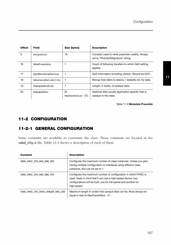
187
Configuration
11
Table 11-3 Metadata Preamble
11-2 CONFIGURATION
11-2-1 GENERAL CONFIGURATION
Some constants are available to customize the class. These constants are located in the
usbd_cfg.h file. Table 11-4 shows a description of each of them.
Offset Field Size (bytes) Description
0 aSignature 16 Constant used to verify preamble validity. Always
set to “PhdcQoSSignature” string.
16 bNumTransfers 1 Count of following transfers to which QoS setting
applies.
17 bQoSEncodingVersion 1 QoS information encoding version. Should be 0x01.
18 bmLatencyReliability 1 Bitmap that refers to latency / reliability bin for data.
19 bOpaqueDataSize 1 Length, in bytes, of opaque data.
20 bOpaqueData [0 ..
MaxPacketSize - 21]
Optional data usually application specific that is
opaque to the class.
Constant Description
USBD_PHDC_CFG_MAX_NBR_DEV Configures the maximum number of class instances. Unless you plan
having multiple configuration or interfaces using different class
instances, this can be set to 1.
USBD_PHDC_CFG_MAX_NBR_CFG Configures the maximum number of configuration in which PHDC is
used. Keep in mind that if you use a high-speed device, two
configurations will be built, one for full-speed and another for
high-speed.
USBD_PHDC_CFG_DATA_OPAQUE_MAX_LEN Maximum length in octets that opaque data can be. Must always be
equal or less to MaxPacketSize - 21.
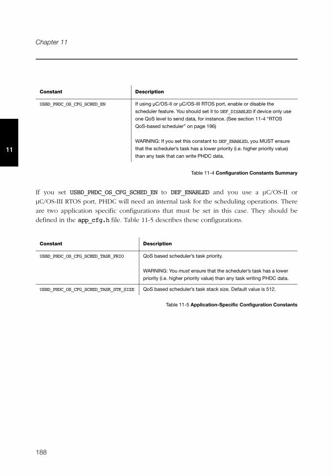
188
Chapter 11
11
Table 11-4 Configuration Constants Summary
If you set USBD_PHDC_OS_CFG_SCHED_EN to DEF_ENABLED and you use a μC/OS-II or
μC/OS-III RTOS port, PHDC will need an internal task for the scheduling operations. There
are two application specific configurations that must be set in this case. They should be
defined in the app_cfg.h file. Table 11-5 describes these configurations.
Table 11-5 Application-Specific Configuration Constants
USBD_PHDC_OS_CFG_SCHED_EN If using μC/OS-II or μC/OS-III RTOS port, enable or disable the
scheduler feature. You should set it to DEF_DISABLED if device only use
one QoS level to send data, for instance. (See section 11-4 “RTOS
QoS-based scheduler” on page 196)
WARNING: If you set this constant to DEF_ENABLED, you MUST ensure
that the scheduler’s task has a lower priority (i.e. higher priority value)
than any task that can write PHDC data.
Constant Description
USBD_PHDC_OS_CFG_SCHED_TASK_PRIO QoS based scheduler’s task priority.
WARNING: You must ensure that the scheduler’s task has a lower
priority (i.e. higher priority value) than any task writing PHDC data.
USBD_PHDC_OS_CFG_SCHED_TASK_STK_SIZE QoS based scheduler’s task stack size. Default value is 512.
Constant Description
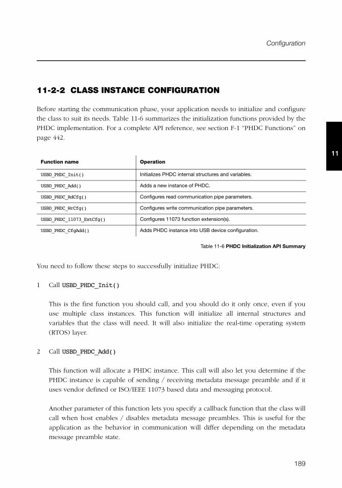
189
Configuration
11
11-2-2 CLASS INSTANCE CONFIGURATION
Before starting the communication phase, your application needs to initialize and configure
the class to suit its needs. Table 11-6 summarizes the initialization functions provided by the
PHDC implementation. For a complete API reference, see section F-1 “PHDC Functions” on
page 442.
Table 11-6 PHDC Initialization API Summary
You need to follow these steps to successfully initialize PHDC:
1 Call USBD_PHDC_Init()
This is the first function you should call, and you should do it only once, even if you
use multiple class instances. This function will initialize all internal structures and
variables that the class will need. It will also initialize the real-time operating system
(RTOS) layer.
2 Call USBD_PHDC_Add()
This function will allocate a PHDC instance. This call will also let you determine if the
PHDC instance is capable of sending / receiving metadata message preamble and if it
uses vendor defined or ISO/IEEE 11073 based data and messaging protocol.
Another parameter of this function lets you specify a callback function that the class will
call when host enables / disables metadata message preambles. This is useful for the
application as the behavior in communication will differ depending on the metadata
message preamble state.
Function name Operation
USBD_PHDC_Init() Initializes PHDC internal structures and variables.
USBD_PHDC_Add() Adds a new instance of PHDC.
USBD_PHDC_RdCfg() Configures read communication pipe parameters.
USBD_PHDC_WrCfg() Configures write communication pipe parameters.
USBD_PHDC_11073_ExtCfg() Configures 11073 function extension(s).
USBD_PHDC_CfgAdd() Adds PHDC instance into USB device configuration.
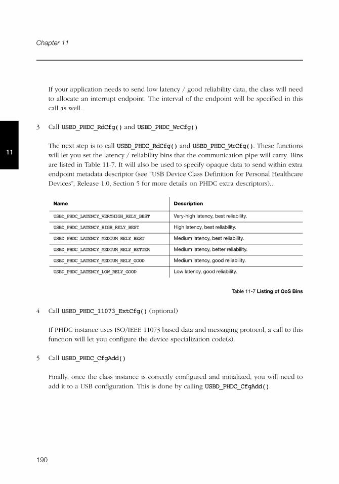
190
Chapter 11
11
If your application needs to send low latency / good reliability data, the class will need
to allocate an interrupt endpoint. The interval of the endpoint will be specified in this
call as well.
3 Call USBD_PHDC_RdCfg() and USBD_PHDC_WrCfg()
The next step is to call USBD_PHDC_RdCfg() and USBD_PHDC_WrCfg(). These functions
will let you set the latency / reliability bins that the communication pipe will carry. Bins
are listed in Table 11-7. It will also be used to specify opaque data to send within extra
endpoint metadata descriptor (see “USB Device Class Definition for Personal Healthcare
Devices”, Release 1.0, Section 5 for more details on PHDC extra descriptors)..
Table 11-7 Listing of QoS Bins
4 Call USBD_PHDC_11073_ExtCfg() (optional)
If PHDC instance uses ISO/IEEE 11073 based data and messaging protocol, a call to this
function will let you configure the device specialization code(s).
5 Call USBD_PHDC_CfgAdd()
Finally, once the class instance is correctly configured and initialized, you will need to
add it to a USB configuration. This is done by calling USBD_PHDC_CfgAdd().
Name Description
USBD_PHDC_LATENCY_VERYHIGH_RELY_BEST Very-high latency, best reliability.
USBD_PHDC_LATENCY_HIGH_RELY_BEST High latency, best reliability.
USBD_PHDC_LATENCY_MEDIUM_RELY_BEST Medium latency, best reliability.
USBD_PHDC_LATENCY_MEDIUM_RELY_BETTER Medium latency, better reliability.
USBD_PHDC_LATENCY_MEDIUM_RELY_GOOD Medium latency, good reliability.
USBD_PHDC_LATENCY_LOW_RELY_GOOD Low latency, good reliability.
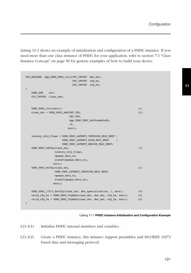
191
Configuration
11
Listing 11-1 shows an example of initialization and configuration of a PHDC instance. If you
need more than one class instance of PHDC for your application, refer to section 7-1 “Class
Instance Concept” on page 99 for generic examples of how to build your device.
Listing 11-1 PHDC Instance Initialization and Configuration Example
L11-1(1) Initialize PHDC internal members and variables.
L11-1(2) Create a PHDC instance, this instance support preambles and ISO/IEEE 11073
based data and messaging protocol.
CPU_BOOLEAN App_USBD_PHDC_Init(CPU_INT08U dev_nbr,
CPU_INT08U cfg_hs,
CPU_INT08U cfg_fs)
{
USBD_ERR err;
CPU_INT08U class_nbr;
USBD_PHDC_Init(&err); (1)
class_nbr = USBD_PHDC_Add(DEF_YES, (2)
DEF_YES,
App_USBD_PHDC_SetPreambleEn,
10,
&err);
latency_rely_flags = USBD_PHDC_LATENCY_VERYHIGH_RELY_BEST |
USBD_PHDC_LATENCY_HIGH_RELY_BEST |
USBD_PHDC_LATENCY_MEDIUM_RELY_BEST;
USBD_PHDC_RdCfg(class_nbr, (3)
latency_rely_flags,
opaque_data_rx,
sizeof(opaque_data_rx),
&err);
USBD_PHDC_WrCfg(class_nbr, (3)
USBD_PHDC_LATENCY_VERYHIGH_RELY_BEST,
opaque_data_tx,
sizeof(opaque_data_tx),
&err);
USBD_PHDC_11073_ExtCfg(class_nbr, dev_specialization, 1, &err); (4)
valid_cfg_hs = USBD_PHDC_CfgAdd(class_nbr, dev_nbr, cfg_hs, &err); (5)
valid_cfg_fs = USBD_PHDC_CfgAdd(class_nbr, dev_nbr, cfg_fs, &err); (6)
}
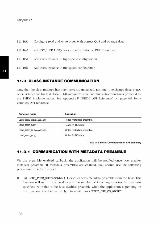
192
Chapter 11
11
L11-1(3) Configure read and write pipes with correct QoS and opaque data.
L11-1(4) Add ISO/IEEE 11073 device specialization to PHDC instance.
L11-1(5) Add class instance to high-speed configuration.
L11-1(6) Add class instance to full-speed configuration.
11-3 CLASS INSTANCE COMMUNICATION
Now that the class instance has been correctly initialized, it’s time to exchange data. PHDC
offers 4 functions for that. Table 11-8 summarizes the communication functions provided by
the PHDC implementation. See Appendix F, “PHDC API Reference” on page 441 for a
complete API reference.
Table 11-8 PHDC Communication API Summary
11-3-1 COMMUNICATION WITH METADATA PREAMBLE
Via the preamble enabled callback, the application will be notified once host enables
metadata preamble. If metadata preambles are enabled, you should use the following
procedure to perform a read:
■ Call USBD_PHDC_RdPreamble(). Device expects metadata preamble from the host. This
function will return opaque data and the number of incoming transfers that the host
specified. Note that if the host disables preamble while the application is pending on
that function, it will immediately return with error “USBD_ERR_OS_ABORT”.
Function name Operation
USBD_PHDC_RdPreamble() Reads metadata preamble.
USBD_PHDC_Rd() Reads PHDC data.
USBD_PHDC_WrPreamble() Writes metadata preamble.
USBD_PHDC_Wr() Writes PHDC data.
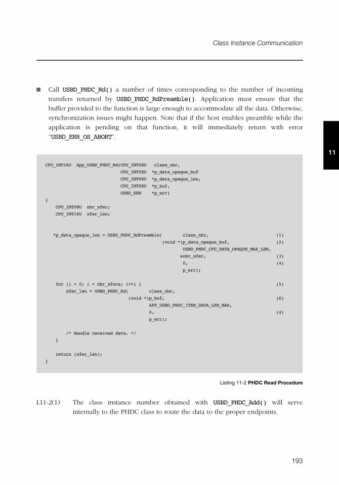
193
Class Instance Communication
11
■ Call USBD_PHDC_Rd() a number of times corresponding to the number of incoming
transfers returned by USBD_PHDC_RdPreamble(). Application must ensure that the
buffer provided to the function is large enough to accommodate all the data. Otherwise,
synchronization issues might happen. Note that if the host enables preamble while the
application is pending on that function, it will immediately return with error
“USBD_ERR_OS_ABORT”.
Listing 11-2 PHDC Read Procedure
L11-2(1) The class instance number obtained with USBD_PHDC_Add() will serve
internally to the PHDC class to route the data to the proper endpoints.
CPU_INT16U App_USBD_PHDC_Rd(CPU_INT08U class_nbr,
CPU_INT08U *p_data_opaque_buf
CPU_INT08U *p_data_opaque_len,
CPU_INT08U *p_buf,
USBD_ERR *p_err)
{
CPU_INT08U nbr_xfer;
CPU_INT16U xfer_len;
*p_data_opaque_len = USBD_PHDC_RdPreamble( class_nbr, (1)
(void *)p_data_opaque_buf, (2)
USBD_PHDC_CFG_DATA_OPAQUE_MAX_LEN,
&nbr_xfer, (3)
0, (4)
p_err);
for (i = 0; i < nbr_xfers; i++) { (5)
xfer_len = USBD_PHDC_Rd( class_nbr,
(void *)p_buf, (6)
APP_USBD_PHDC_ITEM_DATA_LEN_MAX,
0, (4)
p_err);
/* Handle received data. */
}
return (xfer_len);
}

194
Chapter 11
11
L11-2(2) Buffer that will contain opaque data. Application must ensure that the buffer
provided is large enough to accommodate all the data. Otherwise,
synchronization issues might happen.
L11-2(3) Variable that will contain the number of following transfers to which this
preamble applies.
L11-2(4) In order to avoid infinite blocking situation, a timeout expressed in
milliseconds can be specified. A value of ‘0’ makes the application task wait
forever.
L11-2(5) Read all the USB transfers to which the preamble applies.
L11-2(6) Buffer that will contain the data. Application must ensure that the buffer
provided is large enough to accommodate all the data. Otherwise,
synchronization issues might happen.
You should use the following procedure to perform a write:
■ Call USBD_PHDC_WrPreamble(). Host expects metadata preamble from the device.
Application will have to specify opaque data, transfer’s QoS (see Table 11-7), and a
number of following transfers to which the selected QoS applies.
■ Call USBD_PHDC_Wr() a number of times corresponding to the number of transfers
following the preamble.
CPU_INT16U App_USBD_PHDC_Wr(CPU_INT08U class_nbr,
LATENCY_RELY_FLAGS latency_rely,
CPU_INT08U nbr_xfer,
CPU_INT08U *p_data_opaque_buf
CPU_INT08U data_opaque_buf_len,
CPU_INT08U *p_buf,
CPU_INT08U buf_len,
USBD_ERR *p_err)
195
Class Instance Communication
11
Listing 11-3 PHDC Write Procedure
L11-3(1) The class instance number obtained with USBD_PHDC_Add() will serve
internally to the PHDC class to route the data to the proper endpoints.
L11-3(2) Buffer that contains opaque data.
L11-3(3) Latency / reliability (QoS) of the following transfer(s).
L11-3(4) Variable that contains the number of following transfers to which this preamble
will apply.
L11-3(5) In order to avoid infinite blocking situation, a timeout expressed in
milliseconds can be specified. A value of ‘0’ makes the application task wait
forever.
L11-3(6) Write all the USB transfers to which the preamble will apply.
L11-3(7) Buffer that contains the data.
{
(void)USBD_PHDC_WrPreamble( class_nbr, (1)
(void *)p_data_opaque_buf, (2)
data_opaque_buf_len,
latency_rely, (3)
nbr_xfer, (4)
0, (5)
p_err);
for (i = 0; i < nbr_xfer; i++) { (6)
/* Prepare data to send. */
xfer_len = USBD_PHDC_Wr( class_nbr, (1)
(void *)p_buf, (7)
buf_len,
latency_rely, (3)
0,
p_err);
}
}
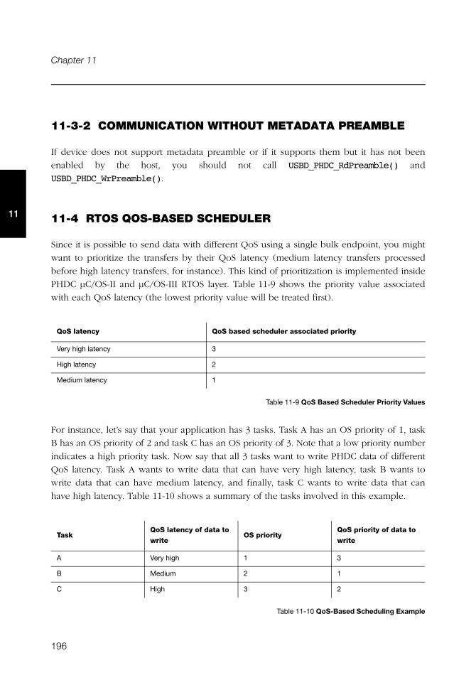
196
Chapter 11
11
11-3-2 COMMUNICATION WITHOUT METADATA PREAMBLE
If device does not support metadata preamble or if it supports them but it has not been
enabled by the host, you should not call USBD_PHDC_RdPreamble() and
USBD_PHDC_WrPreamble().
11-4 RTOS QOS-BASED SCHEDULER
Since it is possible to send data with different QoS using a single bulk endpoint, you might
want to prioritize the transfers by their QoS latency (medium latency transfers processed
before high latency transfers, for instance). This kind of prioritization is implemented inside
PHDC μC/OS-II and μC/OS-III RTOS layer. Table 11-9 shows the priority value associated
with each QoS latency (the lowest priority value will be treated first).
Table 11-9 QoS Based Scheduler Priority Values
For instance, let’s say that your application has 3 tasks. Task A has an OS priority of 1, task
B has an OS priority of 2 and task C has an OS priority of 3. Note that a low priority number
indicates a high priority task. Now say that all 3 tasks want to write PHDC data of different
QoS latency. Task A wants to write data that can have very high latency, task B wants to
write data that can have medium latency, and finally, task C wants to write data that can
have high latency. Table 11-10 shows a summary of the tasks involved in this example.
Table 11-10 QoS-Based Scheduling Example
QoS latency QoS based scheduler associated priority
Very high latency 3
High latency 2
Medium latency 1
TaskQoS latency of data to
writeOS priority
QoS priority of data to
write
A Very high 1 3
B Medium 2 1
C High 3 2

197
RTOS QoS-based scheduler
11
If no QoS based priority management is implemented, the OS will then resume the tasks in
the order of their OS priority. In this example, the task that has the higher OS priority, A,
will be resumed first. However, that task wants to write data that can have very high latency
(QoS priority of 3). A better choice would be to resume task B first, which wants to send
data that can have medium latency (QoS priority of 1). Figure 11-3 and Figure 11-4
represent this example without and with a QoS-based scheduler, respectively.
Figure 11-3 Task Execution Order, Without QoS Based Scheduling
Figure 11-4 Task Execution Order, with QoS Based Scheduling
F11-4(1)
F11-4(2)
F11-4(3) A task currently holds the lock on the write bulk endpoint, task A, B and C are
added to the wait list until the lock is released.
��'1#���#�������5#�
3 �5,0�&0#��� �5#%���
��'1#!��#�������5#/
%��#��� �5#%���
��'1#+��#�������5#:
)�&0#��� �5#%���
��'1
��'1
��'1
��'1#���#�������5#�
3 �5,0�&0#��� �5#%���
��'1#!��#�������5#/
%��#��� �5#%���
��'1#+��#�������5#:
)�&0#��� �5#%���
��'1
��'1
��'1
�)�+#'�0 %� �
��'1
���
�;�
��'1
�9�
��'1
���
�/�
�:�
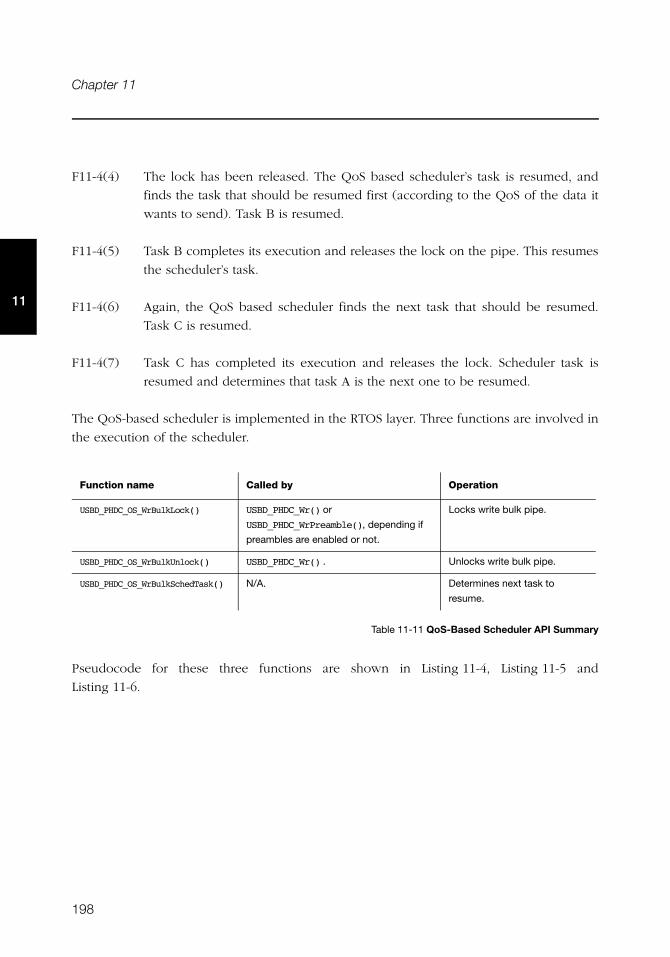
198
Chapter 11
11
F11-4(4) The lock has been released. The QoS based scheduler’s task is resumed, and
finds the task that should be resumed first (according to the QoS of the data it
wants to send). Task B is resumed.
F11-4(5) Task B completes its execution and releases the lock on the pipe. This resumes
the scheduler’s task.
F11-4(6) Again, the QoS based scheduler finds the next task that should be resumed.
Task C is resumed.
F11-4(7) Task C has completed its execution and releases the lock. Scheduler task is
resumed and determines that task A is the next one to be resumed.
The QoS-based scheduler is implemented in the RTOS layer. Three functions are involved in
the execution of the scheduler.
Table 11-11 QoS-Based Scheduler API Summary
Pseudocode for these three functions are shown in Listing 11-4, Listing 11-5 and
Listing 11-6.
Function name Called by Operation
USBD_PHDC_OS_WrBulkLock() USBD_PHDC_Wr() or
USBD_PHDC_WrPreamble(), depending if
preambles are enabled or not.
Locks write bulk pipe.
USBD_PHDC_OS_WrBulkUnlock() USBD_PHDC_Wr() . Unlocks write bulk pipe.
USBD_PHDC_OS_WrBulkSchedTask() N/A. Determines next task to
resume.
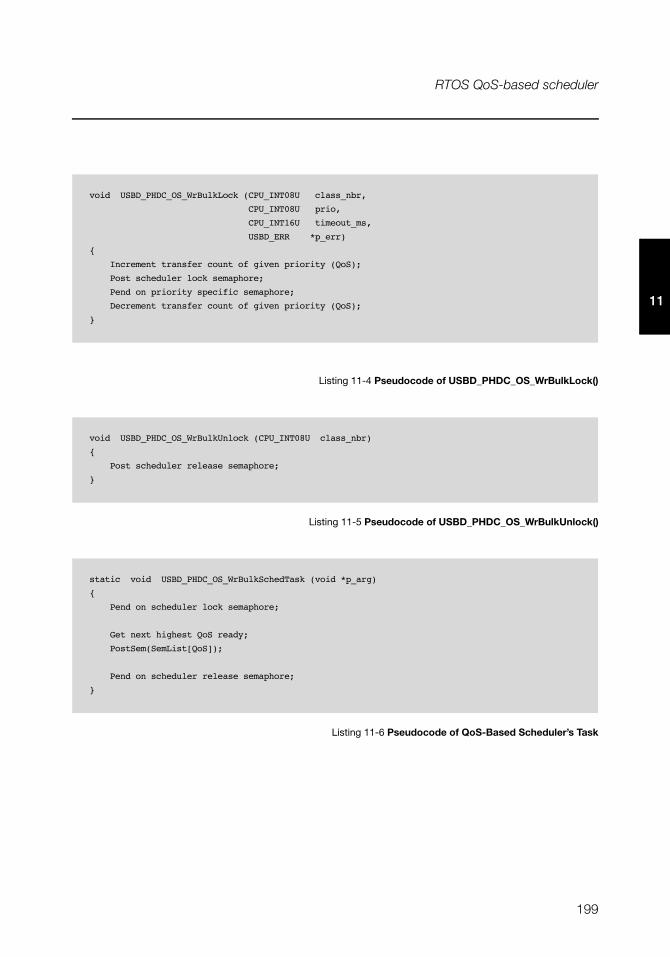
199
RTOS QoS-based scheduler
11
Listing 11-4 Pseudocode of USBD_PHDC_OS_WrBulkLock()
Listing 11-5 Pseudocode of USBD_PHDC_OS_WrBulkUnlock()
Listing 11-6 Pseudocode of QoS-Based Scheduler’s Task
void USBD_PHDC_OS_WrBulkLock (CPU_INT08U class_nbr,
CPU_INT08U prio,
CPU_INT16U timeout_ms,
USBD_ERR *p_err)
{
Increment transfer count of given priority (QoS);
Post scheduler lock semaphore;
Pend on priority specific semaphore;
Decrement transfer count of given priority (QoS);
}
void USBD_PHDC_OS_WrBulkUnlock (CPU_INT08U class_nbr)
{
Post scheduler release semaphore;
}
static void USBD_PHDC_OS_WrBulkSchedTask (void *p_arg)
{
Pend on scheduler lock semaphore;
Get next highest QoS ready;
PostSem(SemList[QoS]);
Pend on scheduler release semaphore;
}
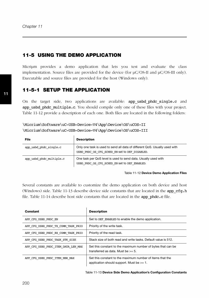
200
Chapter 11
11
11-5 USING THE DEMO APPLICATION
Micriμm provides a demo application that lets you test and evaluate the class
implementation. Source files are provided for the device (for μC/OS-II and μC/OS-III only).
Executable and source files are provided for the host (Windows only).
11-5-1 SETUP THE APPLICATION
On the target side, two applications are available: app_usbd_phdc_single.c and
app_usbd_phdc_multiple.c. You should compile only one of these files with your project.
Table 11-12 provide a description of each one. Both files are located in the following folders:
\Micrium\Software\uC-USB-Device-V4\App\Device\OS\uCOS-II
\Micrium\Software\uC-USB-Device-V4\App\Device\OS\uCOS-III
Table 11-12 Device Demo Application Files
Several constants are available to customize the demo application on both device and host
(Windows) side. Table 11-13 describe device side constants that are located in the app_cfg.h
file. Table 11-14 describe host side constants that are located in the app_phdc.c file.
Table 11-13 Device Side Demo Application’s Configuration Constants
File Description
app_usbd_phdc_single.c Only one task is used to send all data of different QoS. Usually used with
USBD_PHDC_OS_CFG_SCHED_EN set to DEF_DISABLED.
app_usbd_phdc_multiple.c One task per QoS level is used to send data. Usually used with
USBD_PHDC_OS_CFG_SCHED_EN set to DEF_ENABLED.
Constant Description
APP_CFG_USBD_PHDC_EN Set to DEF_ENABLED to enable the demo application.
APP_CFG_USBD_PHDC_TX_COMM_TASK_PRIO Priority of the write task.
APP_CFG_USBD_PHDC_RX_COMM_TASK_PRIO Priority of the read task.
APP_CFG_USBD_PHDC_TASK_STK_SIZE Stack size of both read and write tasks. Default value is 512.
APP_CFG_USBD_PHDC_ITEM_DATA_LEN_MAX Set this constant to the maximum number of bytes that can be
transferred as data. Must be >= 5.
APP_CFG_USBD_PHDC_ITEM_NBR_MAX Set this constant to the maximum number of items that the
application should support. Must be >= 1.
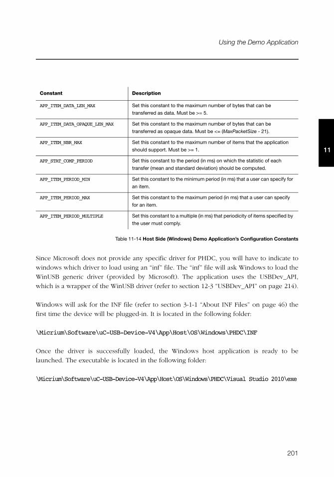
201
Using the Demo Application
11
Table 11-14 Host Side (Windows) Demo Application’s Configuration Constants
Since Microsoft does not provide any specific driver for PHDC, you will have to indicate to
windows which driver to load using an “inf” file. The “inf” file will ask Windows to load the
WinUSB generic driver (provided by Microsoft). The application uses the USBDev_API,
which is a wrapper of the WinUSB driver (refer to section 12-3 “USBDev_API” on page 214).
Windows will ask for the INF file (refer to section 3-1-1 “About INF Files” on page 46) the
first time the device will be plugged-in. It is located in the following folder:
\Micrium\Software\uC-USB-Device-V4\App\Host\OS\Windows\PHDC\INF
Once the driver is successfully loaded, the Windows host application is ready to be
launched. The executable is located in the following folder:
\Micrium\Software\uC-USB-Device-V4\App\Host\OS\Windows\PHDC\Visual Studio 2010\exe
Constant Description
APP_ITEM_DATA_LEN_MAX Set this constant to the maximum number of bytes that can be
transferred as data. Must be >= 5.
APP_ITEM_DATA_OPAQUE_LEN_MAX Set this constant to the maximum number of bytes that can be
transferred as opaque data. Must be <= (MaxPacketSize - 21).
APP_ITEM_NBR_MAX Set this constant to the maximum number of items that the application
should support. Must be >= 1.
APP_STAT_COMP_PERIOD Set this constant to the period (in ms) on which the statistic of each
transfer (mean and standard deviation) should be computed.
APP_ITEM_PERIOD_MIN Set this constant to the minimum period (in ms) that a user can specify for
an item.
APP_ITEM_PERIOD_MAX Set this constant to the maximum period (in ms) that a user can specify
for an item.
APP_ITEM_PERIOD_MULTIPLE Set this constant to a multiple (in ms) that periodicity of items specified by
the user must comply.
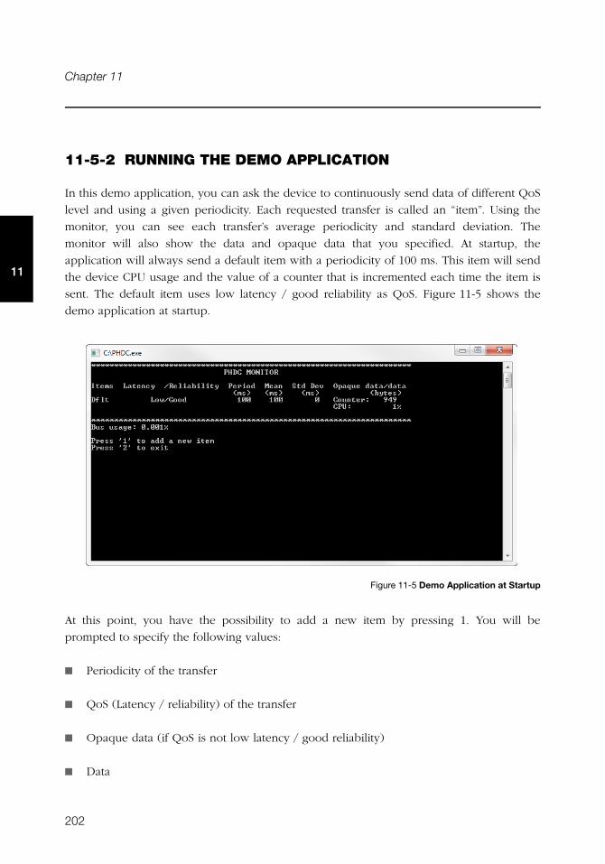
202
Chapter 11
11
11-5-2 RUNNING THE DEMO APPLICATION
In this demo application, you can ask the device to continuously send data of different QoS
level and using a given periodicity. Each requested transfer is called an “item”. Using the
monitor, you can see each transfer’s average periodicity and standard deviation. The
monitor will also show the data and opaque data that you specified. At startup, the
application will always send a default item with a periodicity of 100 ms. This item will send
the device CPU usage and the value of a counter that is incremented each time the item is
sent. The default item uses low latency / good reliability as QoS. Figure 11-5 shows the
demo application at startup.
Figure 11-5 Demo Application at Startup
At this point, you have the possibility to add a new item by pressing 1. You will be
prompted to specify the following values:
■ Periodicity of the transfer
■ QoS (Latency / reliability) of the transfer
■ Opaque data (if QoS is not low latency / good reliability)
■ Data
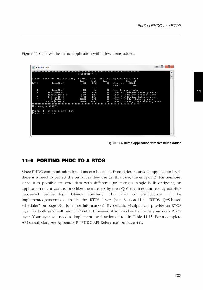
203
Porting PHDC to a RTOS
11
Figure 11-6 shows the demo application with a few items added.
Figure 11-6 Demo Application with five Items Added
11-6 PORTING PHDC TO A RTOS
Since PHDC communication functions can be called from different tasks at application level,
there is a need to protect the resources they use (in this case, the endpoint). Furthermore,
since it is possible to send data with different QoS using a single bulk endpoint, an
application might want to prioritize the transfers by their QoS (i.e. medium latency transfers
processed before high latency transfers). This kind of prioritization can be
implemented/customized inside the RTOS layer (see Section 11-4, “RTOS QoS-based
scheduler” on page 196, for more information). By default, Micriμm will provide an RTOS
layer for both μC/OS-II and μC/OS-III. However, it is possible to create your own RTOS
layer. Your layer will need to implement the functions listed in Table 11-15. For a complete
API description, see Appendix F, “PHDC API Reference” on page 441.
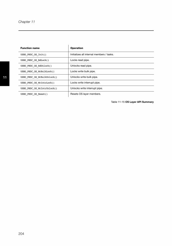
204
Chapter 11
11
Table 11-15 OS Layer API Summary
Function name Operation
USBD_PHDC_OS_Init() Initializes all internal members / tasks.
USBD_PHDC_OS_RdLock() Locks read pipe.
USBD_PHDC_OS_RdUnlock() Unlocks read pipe.
USBD_PHDC_OS_WrBulkLock() Locks write bulk pipe.
USBD_PHDC_OS_WrBulkUnlock() Unlocks write bulk pipe.
USBD_PHDC_OS_WrIntrLock() Locks write interrupt pipe.
USBD_PHDC_OS_WrIntrUnlock() Unlocks write interrupt pipe.
USBD_PHDC_OS_Reset() Resets OS layer members.
205
Chapter
12Vendor Class
The Vendor class allows you to build vendor-specific devices implementing for instance a
proprietary protocol. It relies on a pair of bulk endpoints to transfer data between the host
and the device. Bulk transfers are typically convenient for transferring large amounts of
unstructured data and provides reliable exchange of data by using an error detection and
retry mechanism. Besides bulk endpoints, an optional pair of interrupt endpoints can also
be used. Any operating system (OS) can work with the Vendor class provided that the OS
has a driver to handle the Vendor class. Depending on the OS, the driver can be native or
vendor-specific. For instance, under Microsoft Windows®, your application interacts with
the WinUSB driver provided by Microsoft to communicate with the vendor device.
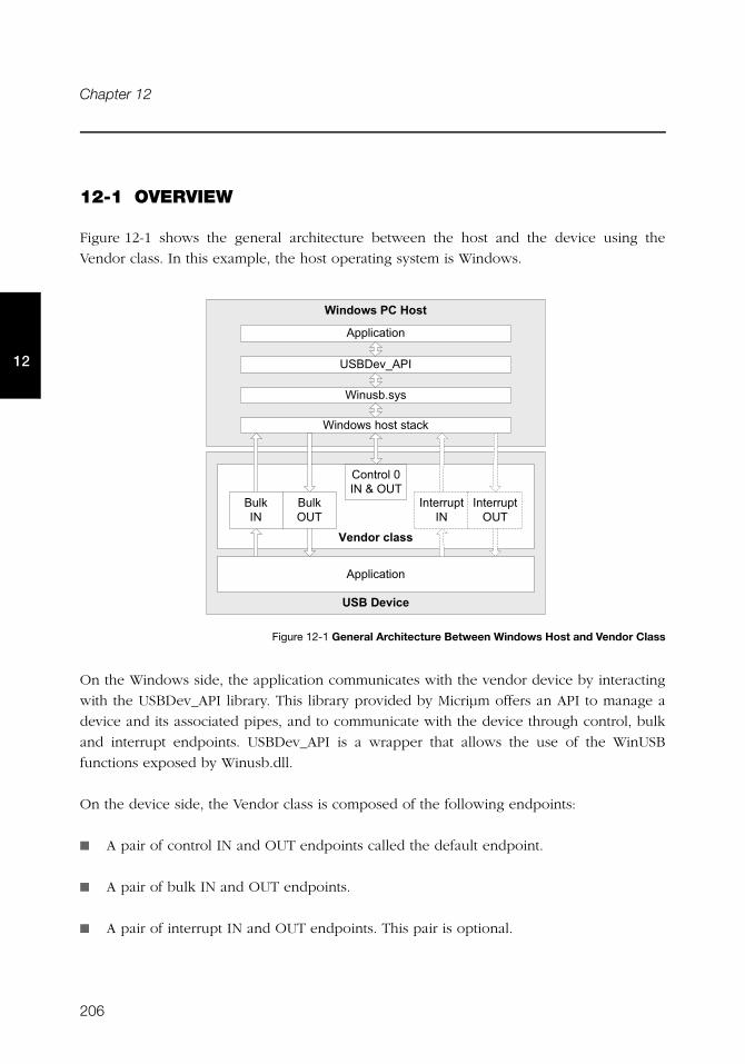
206
Chapter 12
12
12-1 OVERVIEW
Figure 12-1 shows the general architecture between the host and the device using the
Vendor class. In this example, the host operating system is Windows.
Figure 12-1 General Architecture Between Windows Host and Vendor Class
On the Windows side, the application communicates with the vendor device by interacting
with the USBDev_API library. This library provided by Micriμm offers an API to manage a
device and its associated pipes, and to communicate with the device through control, bulk
and interrupt endpoints. USBDev_API is a wrapper that allows the use of the WinUSB
functions exposed by Winusb.dll.
On the device side, the Vendor class is composed of the following endpoints:
■ A pair of control IN and OUT endpoints called the default endpoint.
■ A pair of bulk IN and OUT endpoints.
■ A pair of interrupt IN and OUT endpoints. This pair is optional.
+��, -��.��� ��
'����������
�������'��
E���!#8!<!
E����C!�.�!��!���"
&'(�������
'����������
3��, "��� ��
���"�*
���"�+�
���� ������*
���� �����+�
���� ���)�*�3�+�
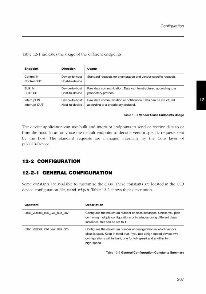
207
Configuration
12
Table 12-1 indicates the usage of the different endpoints:
Table 12-1 Vendor Class Endpoints Usage
The device application can use bulk and interrupt endpoints to send or receive data to or
from the host. It can only use the default endpoint to decode vendor-specific requests sent
by the host. The standard requests are managed internally by the Core layer of
μC/USB-Device.
12-2 CONFIGURATION
12-2-1 GENERAL CONFIGURATION
Some constants are available to customize the class. These constants are located in the USB
device configuration file, usbd_cfg.h. Table 12-2 shows their description.
Table 12-2 General Configuration Constants Summary
Endpoint Direction Usage
Control IN
Control OUT
Device-to-host
Host-to-device
Standard requests for enumeration and vendor-specific requests.
Bulk IN
Bulk OUT
Device-to-host
Host-to-device
Raw data communication. Data can be structured according to a
proprietary protocol.
Interrupt IN
Interrupt OUT
Device-to-host
Host-to-device
Raw data communication or notification. Data can be structured
according to a proprietary protocol.
Constant Description
USBD_VENDOR_CFG_MAX_NBR_DEV Configures the maximum number of class instances. Unless you plan
on having multiple configurations or interfaces using different class
instances, this can be set to 1.
USBD_VENDOR_CFG_MAX_NBR_CFG Configures the maximum number of configuration in which Vendor
class is used. Keep in mind that if you use a high-speed device, two
configurations will be built, one for full-speed and another for
high-speed.
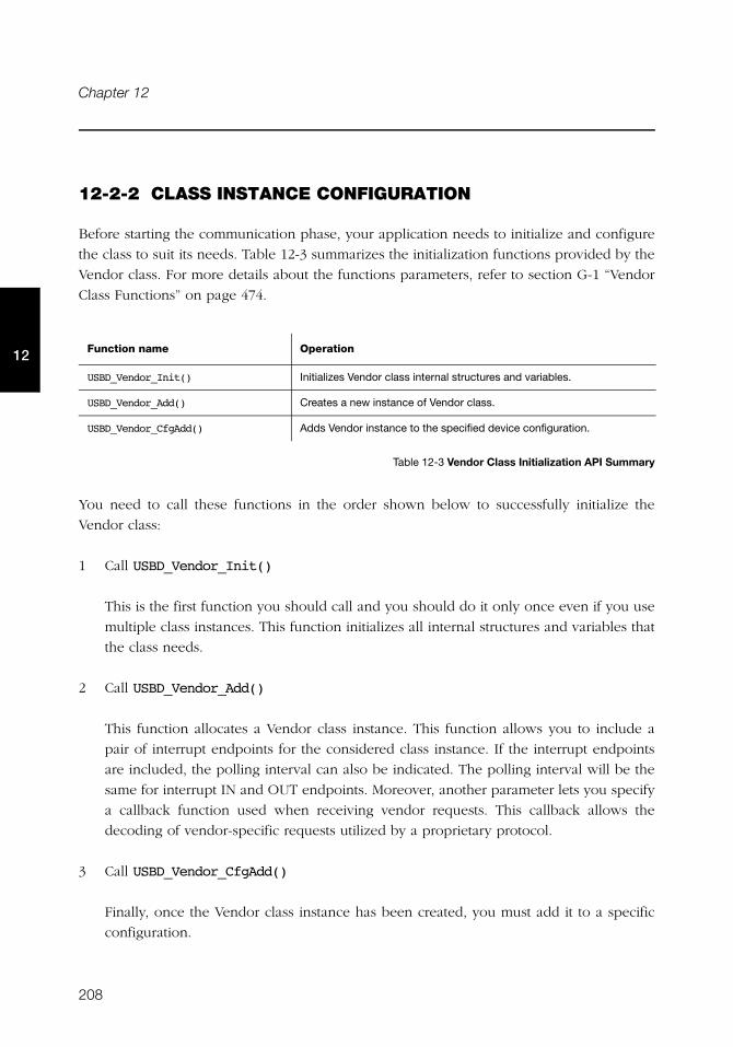
208
Chapter 12
12
12-2-2 CLASS INSTANCE CONFIGURATION
Before starting the communication phase, your application needs to initialize and configure
the class to suit its needs. Table 12-3 summarizes the initialization functions provided by the
Vendor class. For more details about the functions parameters, refer to section G-1 “Vendor
Class Functions” on page 474.
Table 12-3 Vendor Class Initialization API Summary
You need to call these functions in the order shown below to successfully initialize the
Vendor class:
1 Call USBD_Vendor_Init()
This is the first function you should call and you should do it only once even if you use
multiple class instances. This function initializes all internal structures and variables that
the class needs.
2 Call USBD_Vendor_Add()
This function allocates a Vendor class instance. This function allows you to include a
pair of interrupt endpoints for the considered class instance. If the interrupt endpoints
are included, the polling interval can also be indicated. The polling interval will be the
same for interrupt IN and OUT endpoints. Moreover, another parameter lets you specify
a callback function used when receiving vendor requests. This callback allows the
decoding of vendor-specific requests utilized by a proprietary protocol.
3 Call USBD_Vendor_CfgAdd()
Finally, once the Vendor class instance has been created, you must add it to a specific
configuration.
Function name Operation
USBD_Vendor_Init() Initializes Vendor class internal structures and variables.
USBD_Vendor_Add() Creates a new instance of Vendor class.
USBD_Vendor_CfgAdd() Adds Vendor instance to the specified device configuration.
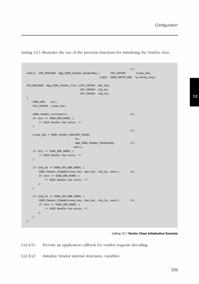
209
Configuration
12
Listing 12-1 illustrates the use of the previous functions for initializing the Vendor class.
Listing 12-1 Vendor Class Initialization Example
L12-1(1) Provide an application callback for vendor requests decoding.
L12-1(2) Initialize Vendor internal structures, variables.
(1)
static CPU_BOOLEAN App_USBD_Vendor_VendorReq ( CPU_INT08U class_nbr,
const USBD_SETUP_REQ *p_setup_req);
CPU_BOOLEAN App_USBD_Vendor_Init (CPU_INT08U dev_nbr,
CPU_INT08U cfg_hs,
CPU_INT08U cfg_fs)
{
USBD_ERR err;
CPU_INT08U class_nbr;
USBD_Vemdor_Init(&err); (2)
if (err != USBD_ERR_NONE) {
/* $$$$ Handle the error. */
}
(3)
class_nbr = USBD_Vendor_Add(DEF_FALSE,
0u,
App_USBD_Vendor_VendorReq, (1)
&err);
if (err != USBD_ERR_NONE) {
/* $$$$ Handle the error. */
}
if (cfg_hs != USBD_CFG_NBR_NONE) {
USBD_Vendor_CfgAdd(class_nbr, dev_nbr, cfg_hs, &err); (4)
if (err != USBD_ERR_NONE) {
/* $$$$ Handle the error. */
}
}
if (cfg_fs != USBD_CFG_NBR_NONE) {
USBD_Vendor_CfgAdd(class_nbr, dev_nbr, cfg_fs, &err); (5)
if (err != USBD_ERR_NONE) {
/* $$$$ Handle the error. */
}
}
}
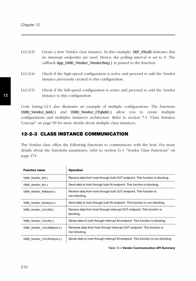
210
Chapter 12
12
L12-1(3) Create a new Vendor class instance. In this example, DEF_FALSE indicates that
no interrupt endpoints are used. Hence, the polling interval is set to 0. The
callback App_USBD_Vendor_VendorReq() is passed to the function.
L12-1(4) Check if the high-speed configuration is active and proceed to add the Vendor
instance previously created to this configuration.
L12-1(5) Check if the full-speed configuration is active and proceed to add the Vendor
instance to this configuration.
Code Listing 12-1 also illustrates an example of multiple configurations. The functions
USBD_Vendor_Add() and USBD_Vendor_CfgAdd() allow you to create multiple
configurations and multiples instances architecture. Refer to section 7-1 “Class Instance
Concept” on page 99 for more details about multiple class instances.
12-2-3 CLASS INSTANCE COMMUNICATION
The Vendor class offers the following functions to communicate with the host. For more
details about the functions parameters, refer to section G-1 “Vendor Class Functions” on
page 474.
Table 12-4 Vendor Communication API Summary
Function name Operation
USBD_Vendor_Rd() Receive data from host through bulk OUT endpoint. This function is blocking.
USBD_Vendor_Wr() Send data to host through bulk IN endpoint. This function is blocking.
USBD_Vendor_RdAsync() Receive data from host through bulk OUT endpoint. This function is
non-blocking.
USBD_Vendor_WrAsync() Send data to host through bulk IN endpoint. This function is non-blocking.
USBD_Vendor_IntrRd() Receive data from host through interrupt OUT endpoint. This function is
blocking.
USBD_Vendor_IntrWr() Sends data to host through interrupt IN endpoint. This function is blocking.
USBD_Vendor_IntrRdAsync() Receives data from host through interrupt OUT endpoint. This function is
non-blocking.
USBD_Vendor_IntrWrAsync() Sends data to host through interrupt IN endpoint. This function is non-blocking.
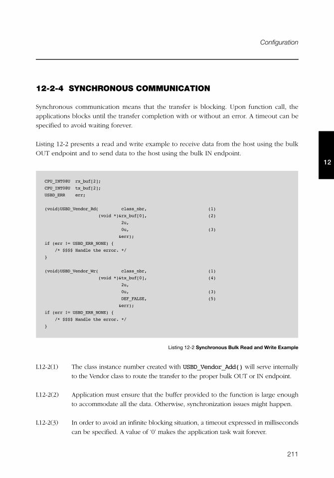
211
Configuration
12
12-2-4 SYNCHRONOUS COMMUNICATION
Synchronous communication means that the transfer is blocking. Upon function call, the
applications blocks until the transfer completion with or without an error. A timeout can be
specified to avoid waiting forever.
Listing 12-2 presents a read and write example to receive data from the host using the bulk
OUT endpoint and to send data to the host using the bulk IN endpoint.
Listing 12-2 Synchronous Bulk Read and Write Example
L12-2(1) The class instance number created with USBD_Vendor_Add() will serve internally
to the Vendor class to route the transfer to the proper bulk OUT or IN endpoint.
L12-2(2) Application must ensure that the buffer provided to the function is large enough
to accommodate all the data. Otherwise, synchronization issues might happen.
L12-2(3) In order to avoid an infinite blocking situation, a timeout expressed in milliseconds
can be specified. A value of ‘0’ makes the application task wait forever.
CPU_INT08U rx_buf[2];
CPU_INT08U tx_buf[2];
USBD_ERR err;
(void)USBD_Vendor_Rd( class_nbr, (1)
(void *)&rx_buf[0], (2)
2u,
0u, (3)
&err);
if (err != USBD_ERR_NONE) {
/* $$$$ Handle the error. */
}
(void)USBD_Vendor_Wr( class_nbr, (1)
(void *)&tx_buf[0], (4)
2u,
0u, (3)
DEF_FALSE, (5)
&err);
if (err != USBD_ERR_NONE) {
/* $$$$ Handle the error. */
}
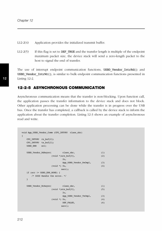
212
Chapter 12
12
L12-2(4) Application provides the initialized transmit buffer.
L12-2(5) If this flag is set to DEF_TRUE and the transfer length is multiple of the endpoint
maximum packet size, the device stack will send a zero-length packet to the
host to signal the end of transfer.
The use of interrupt endpoint communication functions, USBD_Vendor_IntrRd() and
USBD_Vendor_IntrWr(), is similar to bulk endpoint communication functions presented in
Listing 12-2.
12-2-5 ASYNCHRONOUS COMMUNICATION
Asynchronous communication means that the transfer is non-blocking. Upon function call,
the application passes the transfer information to the device stack and does not block.
Other application processing can be done while the transfer is in progress over the USB
bus. Once the transfer has completed, a callback is called by the device stack to inform the
application about the transfer completion. Listing 12-3 shows an example of asynchronous
read and write.
void App_USBD_Vendor_Comm (CPU_INT08U class_nbr)
{
CPU_INT08U rx_buf[2];
CPU_INT08U tx_buf[2];
USBD_ERR err;
USBD_Vendor_RdAsync( class_nbr, (1)
(void *)&rx_buf[0], (2)
2u,
App_USBD_Vendor_RxCmpl, (3)
(void *) 0u, (4)
&err);
if (err != USBD_ERR_NONE) {
/* $$$$ Handle the error. */
}
USBD_Vendor_WrAsync( class_nbr, (1)
(void *)&tx_buf[0], (5)
2u,
App_USBD_Vendor_TxCmpl, (3)
(void *) 0u, (4)
DEF_FALSE, (6)
&err);
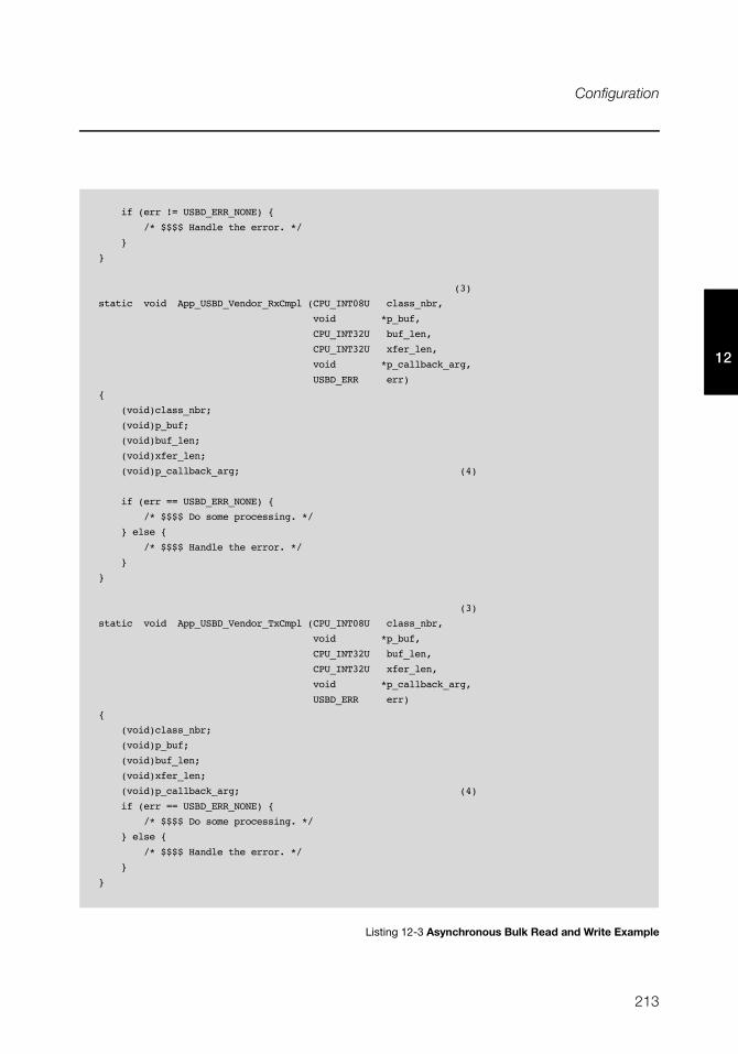
213
Configuration
12
Listing 12-3 Asynchronous Bulk Read and Write Example
if (err != USBD_ERR_NONE) {
/* $$$$ Handle the error. */
}
}
(3)
static void App_USBD_Vendor_RxCmpl (CPU_INT08U class_nbr,
void *p_buf,
CPU_INT32U buf_len,
CPU_INT32U xfer_len,
void *p_callback_arg,
USBD_ERR err)
{
(void)class_nbr;
(void)p_buf;
(void)buf_len;
(void)xfer_len;
(void)p_callback_arg; (4)
if (err == USBD_ERR_NONE) {
/* $$$$ Do some processing. */
} else {
/* $$$$ Handle the error. */
}
}
(3)
static void App_USBD_Vendor_TxCmpl (CPU_INT08U class_nbr,
void *p_buf,
CPU_INT32U buf_len,
CPU_INT32U xfer_len,
void *p_callback_arg,
USBD_ERR err)
{
(void)class_nbr;
(void)p_buf;
(void)buf_len;
(void)xfer_len;
(void)p_callback_arg; (4)
if (err == USBD_ERR_NONE) {
/* $$$$ Do some processing. */
} else {
/* $$$$ Handle the error. */
}
}
214
Chapter 12
12
L12-3(1) The class instance number serves internally to the Vendor class to route the
transfer to the proper bulk OUT or IN endpoint.
L12-3(2) Application must ensure that the buffer provided to the function is large
enough to accommodate all the data. Otherwise, synchronization issues might
happen.
L12-3(3) The application provides a callback passed as a parameter. Upon completion of
the transfer, the device stack calls this callback so that the application can
finalize the transfer by analyzing the transfer result. For instance, upon read
operation completion, the application may do a certain processing with the
received data. Upon write completion, the application may indicate if the write
was successful and how many bytes were sent.
L12-3(4) An argument associated to the callback can be also passed. Then in the
callback context, some private information can be retrieved.
L12-3(5) Application provides the initialized transmit buffer.
L12-3(6) If this flag is set to DEF_TRUE and the transfer length is a multiple of the
endpoint maximum packet size, the device stack will send a zero-length packet
to the host to signal the end of transfer.
The use of interrupt endpoint communication functions, USBD_Vendor_IntrRdAsync() and
USBD_Vendor_IntrWrAsync(), is similar to bulk endpoint communication functions
presented in Listing 12-3.
12-3 USBDev_API
Windows application communicates with a vendor device through USBDev_API. The latter
is a wrapper developed by Micriμm allowing the application to access the WinUSB
functionalities to manage a USB device. Windows USB (WinUSB) is a generic driver for USB
devices. The WinUSB architecture consists of a kernel-mode driver (Winusb.sys) and a
user-mode dynamic link library (Winusb.dll) that exposes WinUSB functions. USBDev_API
eases the use of WinUSB by providing a comprehensive API (refer to section G-2
“USBDev_API Functions” on page 497 for the complete list). Figure 12-2 shows the
USBDev_API library and WinUSB.
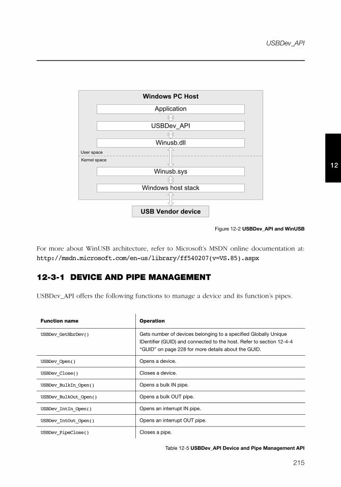
215
USBDev_API
12
Figure 12-2 USBDev_API and WinUSB
For more about WinUSB architecture, refer to Microsoft’s MSDN online documentation at:
http://msdn.microsoft.com/en-us/library/ff540207(v=VS.85).aspx
12-3-1 DEVICE AND PIPE MANAGEMENT
USBDev_API offers the following functions to manage a device and its function’s pipes.
Table 12-5 USBDev_API Device and Pipe Management API
Function name Operation
USBDev_GetNbrDev() Gets number of devices belonging to a specified Globally Unique
IDentifier (GUID) and connected to the host. Refer to section 12-4-4
“GUID” on page 228 for more details about the GUID.
USBDev_Open() Opens a device.
USBDev_Close() Closes a device.
USBDev_BulkIn_Open() Opens a bulk IN pipe.
USBDev_BulkOut_Open() Opens a bulk OUT pipe.
USBDev_IntIn_Open() Opens an interrupt IN pipe.
USBDev_IntOut_Open() Opens an interrupt OUT pipe.
USBDev_PipeClose() Closes a pipe.
+��, -��.��� ��
'����������
�������'��
E���!#8!<!
E����C!�.�!��!���"
E���!#8����!� �!����
F� ����!����
&'(�3��, "�,�����
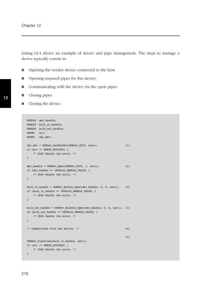
216
Chapter 12
12
Listing 12-4 shows an example of device and pipe management. The steps to manage a
device typically consist in:
■ Opening the vendor device connected to the host.
■ Opening required pipes for this device.
■ Communicating with the device via the open pipes.
■ Closing pipes.
■ Closing the device.
HANDLE dev_handle;
HANDLE bulk_in_handle;
HANDLE bulk_out_handle;
DWORD err;
DWORD nbr_dev;
nbr_dev = USBDev_GetNbrDev(USBDev_GUID, &err); (1)
if (err != ERROR_SUCCESS) {
/* $$$$ Handle the error. */
}
dev_handle = USBDev_Open(USBDev_GUID, 1, &err); (2)
if (dev_handle == INVALID_HANDLE_VALUE) {
/* $$$$ Handle the error. */
}
bulk_in_handle = USBDev_BulkIn_Open(dev_handle, 0, 0, &err); (3)
if (bulk_in_handle == INVALID_HANDLE_VALUE) {
/* $$$$ Handle the error. */
}
bulk_out_handle = USBDev_BulkOut_Open(dev_handle, 0, 0, &err); (3)
if (bulk_out_handle == INVALID_HANDLE_VALUE) {
/* $$$$ Handle the error. */
}
/* Communicate with the device. */ (4)
(5)
USBDev_PipeClose(bulk_in_handle, &err);
if (err != ERROR_SUCCESS) {
/* $$$$ Handle the error. */
}
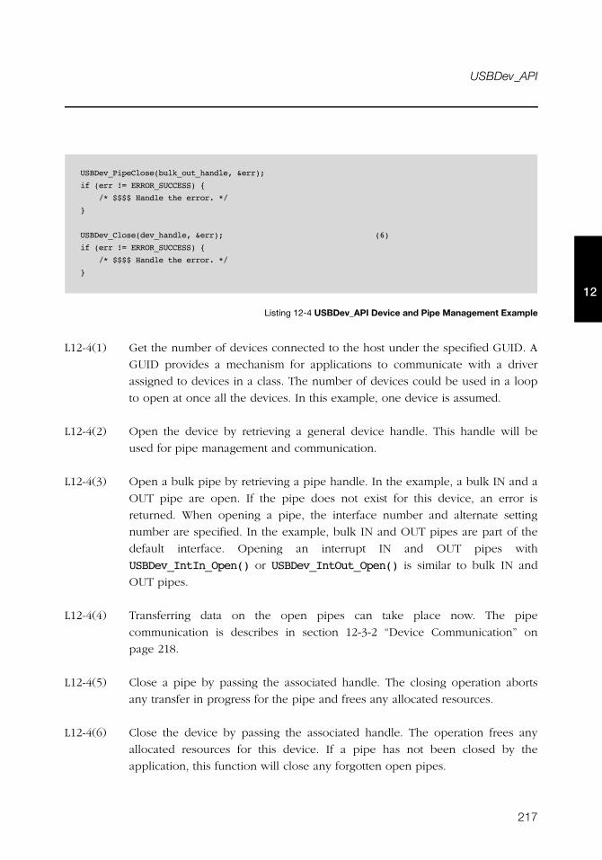
217
USBDev_API
12
Listing 12-4 USBDev_API Device and Pipe Management Example
L12-4(1) Get the number of devices connected to the host under the specified GUID. A
GUID provides a mechanism for applications to communicate with a driver
assigned to devices in a class. The number of devices could be used in a loop
to open at once all the devices. In this example, one device is assumed.
L12-4(2) Open the device by retrieving a general device handle. This handle will be
used for pipe management and communication.
L12-4(3) Open a bulk pipe by retrieving a pipe handle. In the example, a bulk IN and a
OUT pipe are open. If the pipe does not exist for this device, an error is
returned. When opening a pipe, the interface number and alternate setting
number are specified. In the example, bulk IN and OUT pipes are part of the
default interface. Opening an interrupt IN and OUT pipes with
USBDev_IntIn_Open() or USBDev_IntOut_Open() is similar to bulk IN and
OUT pipes.
L12-4(4) Transferring data on the open pipes can take place now. The pipe
communication is describes in section 12-3-2 “Device Communication” on
page 218.
L12-4(5) Close a pipe by passing the associated handle. The closing operation aborts
any transfer in progress for the pipe and frees any allocated resources.
L12-4(6) Close the device by passing the associated handle. The operation frees any
allocated resources for this device. If a pipe has not been closed by the
application, this function will close any forgotten open pipes.
USBDev_PipeClose(bulk_out_handle, &err);
if (err != ERROR_SUCCESS) {
/* $$$$ Handle the error. */
}
USBDev_Close(dev_handle, &err); (6)
if (err != ERROR_SUCCESS) {
/* $$$$ Handle the error. */
}
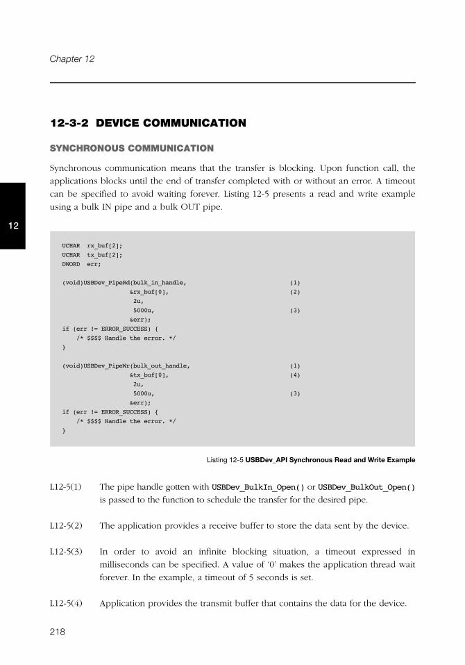
218
Chapter 12
12
12-3-2 DEVICE COMMUNICATION
SYNCHRONOUS COMMUNICATION
Synchronous communication means that the transfer is blocking. Upon function call, the
applications blocks until the end of transfer completed with or without an error. A timeout
can be specified to avoid waiting forever. Listing 12-5 presents a read and write example
using a bulk IN pipe and a bulk OUT pipe.
Listing 12-5 USBDev_API Synchronous Read and Write Example
L12-5(1) The pipe handle gotten with USBDev_BulkIn_Open() or USBDev_BulkOut_Open()
is passed to the function to schedule the transfer for the desired pipe.
L12-5(2) The application provides a receive buffer to store the data sent by the device.
L12-5(3) In order to avoid an infinite blocking situation, a timeout expressed in
milliseconds can be specified. A value of ‘0’ makes the application thread wait
forever. In the example, a timeout of 5 seconds is set.
L12-5(4) Application provides the transmit buffer that contains the data for the device.
UCHAR rx_buf[2];
UCHAR tx_buf[2];
DWORD err;
(void)USBDev_PipeRd(bulk_in_handle, (1)
&rx_buf[0], (2)
2u,
5000u, (3)
&err);
if (err != ERROR_SUCCESS) {
/* $$$$ Handle the error. */
}
(void)USBDev_PipeWr(bulk_out_handle, (1)
&tx_buf[0], (4)
2u,
5000u, (3)
&err);
if (err != ERROR_SUCCESS) {
/* $$$$ Handle the error. */
}
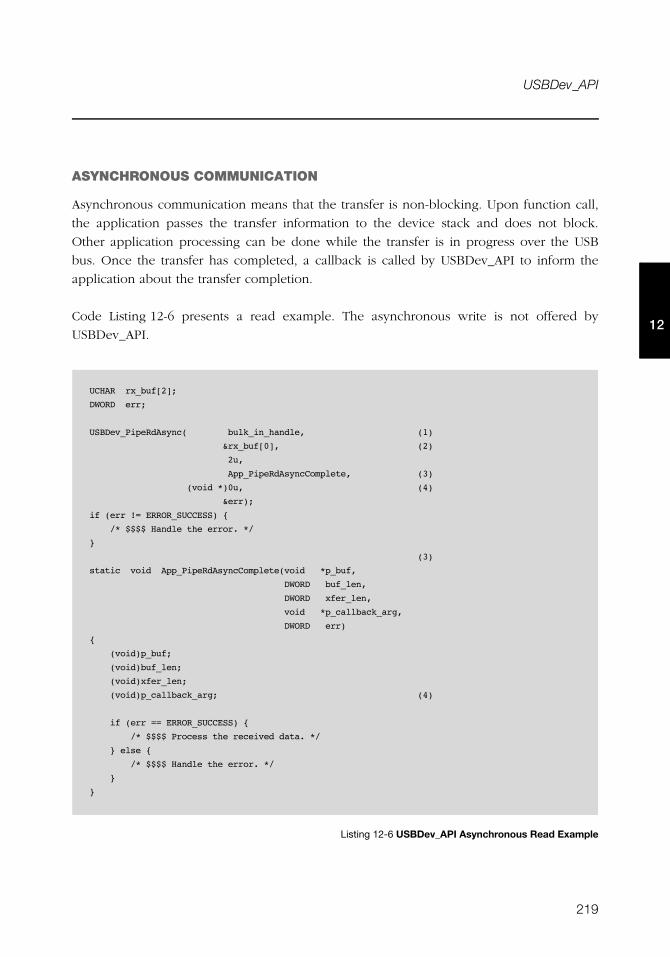
219
USBDev_API
12
ASYNCHRONOUS COMMUNICATION
Asynchronous communication means that the transfer is non-blocking. Upon function call,
the application passes the transfer information to the device stack and does not block.
Other application processing can be done while the transfer is in progress over the USB
bus. Once the transfer has completed, a callback is called by USBDev_API to inform the
application about the transfer completion.
Code Listing 12-6 presents a read example. The asynchronous write is not offered by
USBDev_API.
Listing 12-6 USBDev_API Asynchronous Read Example
UCHAR rx_buf[2];
DWORD err;
USBDev_PipeRdAsync( bulk_in_handle, (1)
&rx_buf[0], (2)
2u,
App_PipeRdAsyncComplete, (3)
(void *)0u, (4)
&err);
if (err != ERROR_SUCCESS) {
/* $$$$ Handle the error. */
}
(3)
static void App_PipeRdAsyncComplete(void *p_buf,
DWORD buf_len,
DWORD xfer_len,
void *p_callback_arg,
DWORD err)
{
(void)p_buf;
(void)buf_len;
(void)xfer_len;
(void)p_callback_arg; (4)
if (err == ERROR_SUCCESS) {
/* $$$$ Process the received data. */
} else {
/* $$$$ Handle the error. */
}
}
220
Chapter 12
12
L12-6(1) The pipe handle gotten with USBDev_BulkIn_Open() is passed to the function
to schedule the transfer for the desired pipe.
L12-6(2) The application provides a receive buffer to store the data sent by the device.
L12-6(3) The application provides a callback passed as a parameter. Upon completion of
the transfer, USBDev_API calls this callback so that the application can finalize
the transfer by analyzing the transfer result. For instance, upon read operation
completion, the application may do a certain processing with the received data.
L12-6(4) An argument associated to the callback can be also passed. Then in the
callback context, some private information can be retrieved.
12-4 USING THE DEMO APPLICATION
Micriμm provides a demo application that lets you test and evaluate the class
implementation. Source template files are provided for the device. Executable and source
files are provided for Windows host PC.
12-4-1 CONFIGURING PC AND DEVICE APPLICATIONS
The demo used between the host and the device is the Echo demo. This demo implements
a simple protocol allowing the device to echo the data sent by the host.
On the device side, the demo application file, app_usbd_vendor.c, provided for μC/OS-II
and μC/OS-III is located in these two folders:
■ \Micrium\Software\uC-USB-Device-V4\App\Device\OS\uCOS-II
■ \Micrium\Software\uC-USB-Device-V4\App\Device\OS\uCOS-III
app_usbd_vendor.c contains the Echo demo available in two versions:
■ The Echo Sync demo exercises the synchronous communication API described in
section 12-2-4 “Synchronous Communication” on page 211.
■ The Echo Async demo exercises the asynchronous communication API described in
section 12-2-5 “Asynchronous Communication” on page 212.
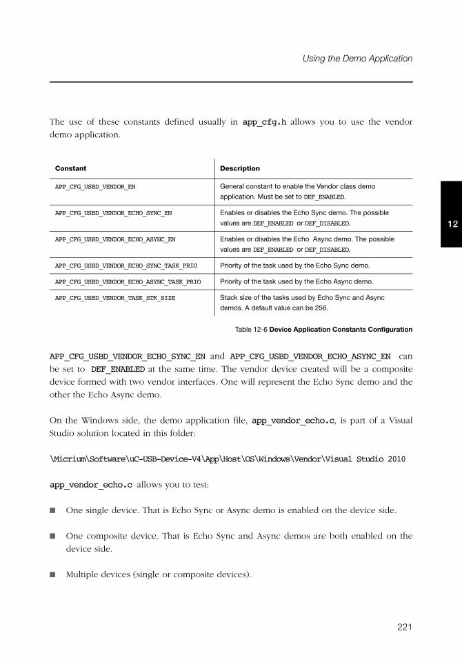
221
Using the Demo Application
12
The use of these constants defined usually in app_cfg.h allows you to use the vendor
demo application.
Table 12-6 Device Application Constants Configuration
APP_CFG_USBD_VENDOR_ECHO_SYNC_EN and APP_CFG_USBD_VENDOR_ECHO_ASYNC_EN can
be set to DEF_ENABLED at the same time. The vendor device created will be a composite
device formed with two vendor interfaces. One will represent the Echo Sync demo and the
other the Echo Async demo.
On the Windows side, the demo application file, app_vendor_echo.c, is part of a Visual
Studio solution located in this folder:
\Micrium\Software\uC-USB-Device-V4\App\Host\OS\Windows\Vendor\Visual Studio 2010
app_vendor_echo.c allows you to test:
■ One single device. That is Echo Sync or Async demo is enabled on the device side.
■ One composite device. That is Echo Sync and Async demos are both enabled on the
device side.
■ Multiple devices (single or composite devices).
Constant Description
APP_CFG_USBD_VENDOR_EN General constant to enable the Vendor class demo
application. Must be set to DEF_ENABLED.
APP_CFG_USBD_VENDOR_ECHO_SYNC_EN Enables or disables the Echo Sync demo. The possible
values are DEF_ENABLED or DEF_DISABLED.
APP_CFG_USBD_VENDOR_ECHO_ASYNC_EN Enables or disables the Echo Async demo. The possible
values are DEF_ENABLED or DEF_DISABLED.
APP_CFG_USBD_VENDOR_ECHO_SYNC_TASK_PRIO Priority of the task used by the Echo Sync demo.
APP_CFG_USBD_VENDOR_ECHO_ASYNC_TASK_PRIO Priority of the task used by the Echo Async demo.
APP_CFG_USBD_VENDOR_TASK_STK_SIZE Stack size of the tasks used by Echo Sync and Async
demos. A default value can be 256.
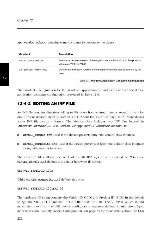
222
Chapter 12
12
app_vendor_echo.c contains some constants to customize the demo.
Table 12-7 Windows Application Constants Configuration
The constants configuration for the Windows application are independent from the device
application constants configuration presented in Table 12-6.
12-4-2 EDITING AN INF FILE
An INF file contains directives telling to Windows how to install one or several drivers for
one or more devices. Refer to section 3-1-1 “About INF Files” on page 46 for more details
about INF file use and format. The Vendor class includes two INF files located in
\Micrium\Software\uC-USB-Device-V4\App\Host\OS\Windows\Vendor\INF:
■ WinUSB_single.inf, used if the device presents only one Vendor class interface.
■ WinUSB_composite.inf, used if the device presents at least one Vendor class interface
along with another interface.
The two INF files allows you to load the WinUSB.sys driver provided by Windows.
WinUSB_single.inf defines this default hardware ID string:
USB\VID_FFFE&PID_1003
While WinUSB_composite.inf defines this one:
USB\VID_FFFE&PID_1001&MI_00
The hardware ID string contains the Vendor ID (VID) and Product ID (PID). In the default
strings, the VID is FFFE and the PID is either 1003 or 1001. The VID/PID values should
match the ones from the USB device configuration structure defined in usb_dev_cfg.c.
Refer to section “Modify Device Configuration” on page 34 for more details about the USB
Constant Description
APP_CFG_RX_ASYNC_EN Enables or disables the use of the asynchronous API for IN pipe. The possible
values are TRUE or FALSE.
APP_MAX_NBR_VENDOR_DEV Defines the maximum number of connected vendor devices supported by the
demo.
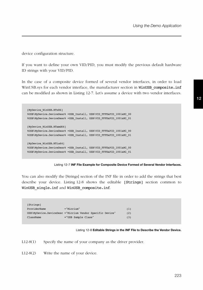
223
Using the Demo Application
12
device configuration structure.
If you want to define your own VID/PID, you must modify the previous default hardware
ID strings with your VID/PID.
In the case of a composite device formed of several vendor interfaces, in order to load
WinUSB.sys for each vendor interface, the manufacturer section in WinUSB_composite.inf
can be modified as shown in Listing 12-7. Let’s assume a device with two vendor interfaces.
Listing 12-7 INF File Example for Composite Device Formed of Several Vendor Interfaces.
You can also modify the [Strings] section of the INF file in order to add the strings that best
describe your device. Listing 12-8 shows the editable [Strings] section common to
WinUSB_single.inf and WinUSB_composite.inf.
Listing 12-8 Editable Strings in the INF File to Describe the Vendor Device.
L12-8(1) Specify the name of your company as the driver provider.
L12-8(2) Write the name of your device.
[MyDevice_WinUSB.NTx86]
%USB\MyDevice.DeviceDesc% =USB_Install, USB\VID_FFFE&PID_1001&MI_00
%USB\MyDevice.DeviceDesc% =USB_Install, USB\VID_FFFE&PID_1001&MI_01
[MyDevice_WinUSB.NTamd64]
%USB\MyDevice.DeviceDesc% =USB_Install, USB\VID_FFFE&PID_1001&MI_00
%USB\MyDevice.DeviceDesc% =USB_Install, USB\VID_FFFE&PID_1001&MI_01
[MyDevice_WinUSB.NTia64]
%USB\MyDevice.DeviceDesc% =USB_Install, USB\VID_FFFE&PID_1001&MI_00
%USB\MyDevice.DeviceDesc% =USB_Install, USB\VID_FFFE&PID_1001&MI_01
[Strings]
ProviderName ="Micrium" (1)
USB\MyDevice.DeviceDesc ="Micrium Vendor Specific Device" (2)
ClassName ="USB Sample Class" (3)
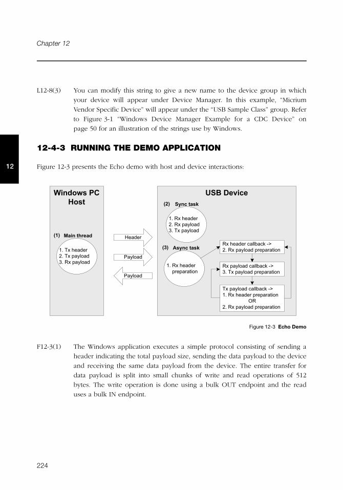
224
Chapter 12
12
L12-8(3) You can modify this string to give a new name to the device group in which
your device will appear under Device Manager. In this example, “Micrium
Vendor Specific Device” will appear under the “USB Sample Class” group. Refer
to Figure 3-1 “Windows Device Manager Example for a CDC Device” on
page 50 for an illustration of the strings use by Windows.
12-4-3 RUNNING THE DEMO APPLICATION
Figure 12-3 presents the Echo demo with host and device interactions:
Figure 12-3 Echo Demo
F12-3(1) The Windows application executes a simple protocol consisting of sending a
header indicating the total payload size, sending the data payload to the device
and receiving the same data payload from the device. The entire transfer for
data payload is split into small chunks of write and read operations of 512
bytes. The write operation is done using a bulk OUT endpoint and the read
uses a bulk IN endpoint.
&'(�������+��, -��.��� ��
�.���� �����#��"�-G�/8����<������ ��� �����08� �.����
/8� ���<����18����<����
08��.���� /8����<����18� ���<����
08��.���� ������ ��� �����
�����
��<����
��<����
���<���������#��"�-G�18� ���<������ ��� �����
���<���������#��"�-G�08��.���� �� ��� �����
+�/8����<������ ��� �����
'$���� �/
2�$���� �/
1 ����4"� ,���
���
���
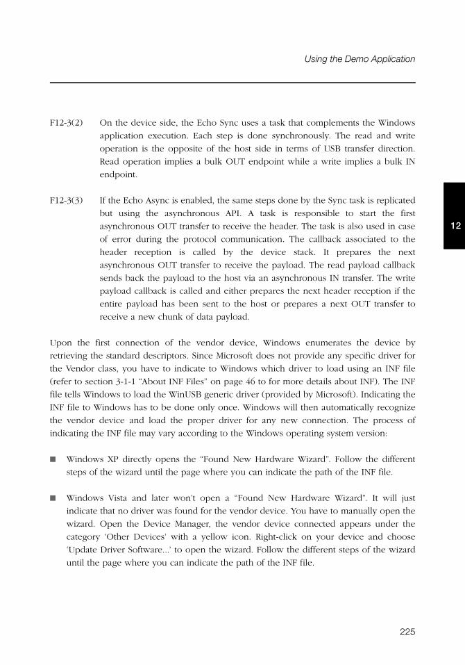
225
Using the Demo Application
12
F12-3(2) On the device side, the Echo Sync uses a task that complements the Windows
application execution. Each step is done synchronously. The read and write
operation is the opposite of the host side in terms of USB transfer direction.
Read operation implies a bulk OUT endpoint while a write implies a bulk IN
endpoint.
F12-3(3) If the Echo Async is enabled, the same steps done by the Sync task is replicated
but using the asynchronous API. A task is responsible to start the first
asynchronous OUT transfer to receive the header. The task is also used in case
of error during the protocol communication. The callback associated to the
header reception is called by the device stack. It prepares the next
asynchronous OUT transfer to receive the payload. The read payload callback
sends back the payload to the host via an asynchronous IN transfer. The write
payload callback is called and either prepares the next header reception if the
entire payload has been sent to the host or prepares a next OUT transfer to
receive a new chunk of data payload.
Upon the first connection of the vendor device, Windows enumerates the device by
retrieving the standard descriptors. Since Microsoft does not provide any specific driver for
the Vendor class, you have to indicate to Windows which driver to load using an INF file
(refer to section 3-1-1 “About INF Files” on page 46 to for more details about INF). The INF
file tells Windows to load the WinUSB generic driver (provided by Microsoft). Indicating the
INF file to Windows has to be done only once. Windows will then automatically recognize
the vendor device and load the proper driver for any new connection. The process of
indicating the INF file may vary according to the Windows operating system version:
■ Windows XP directly opens the “Found New Hardware Wizard”. Follow the different
steps of the wizard until the page where you can indicate the path of the INF file.
■ Windows Vista and later won’t open a “Found New Hardware Wizard”. It will just
indicate that no driver was found for the vendor device. You have to manually open the
wizard. Open the Device Manager, the vendor device connected appears under the
category ‘Other Devices’ with a yellow icon. Right-click on your device and choose
‘Update Driver Software...’ to open the wizard. Follow the different steps of the wizard
until the page where you can indicate the path of the INF file.
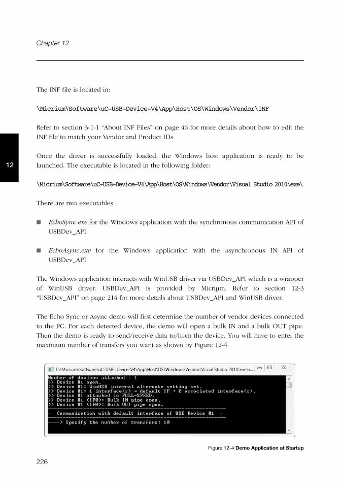
226
Chapter 12
12
The INF file is located in:
\Micrium\Software\uC-USB-Device-V4\App\Host\OS\Windows\Vendor\INF
Refer to section 3-1-1 “About INF Files” on page 46 for more details about how to edit the
INF file to match your Vendor and Product IDs.
Once the driver is successfully loaded, the Windows host application is ready to be
launched. The executable is located in the following folder:
\Micrium\Software\uC-USB-Device-V4\App\Host\OS\Windows\Vendor\Visual Studio 2010\exe\
There are two executables:
■ EchoSync.exe for the Windows application with the synchronous communication API of
USBDev_API.
■ EchoAsync.exe for the Windows application with the asynchronous IN API of
USBDev_API.
The Windows application interacts with WinUSB driver via USBDev_API which is a wrapper
of WinUSB driver. USBDev_API is provided by Micriμm. Refer to section 12-3
“USBDev_API” on page 214 for more details about USBDev_API and WinUSB driver.
The Echo Sync or Async demo will first determine the number of vendor devices connected
to the PC. For each detected device, the demo will open a bulk IN and a bulk OUT pipe.
Then the demo is ready to send/receive data to/from the device. You will have to enter the
maximum number of transfers you want as shown by Figure 12-4.
Figure 12-4 Demo Application at Startup
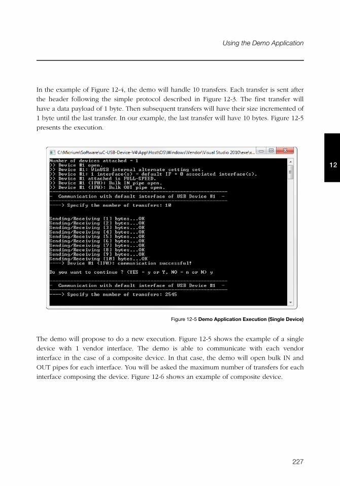
227
Using the Demo Application
12
In the example of Figure 12-4, the demo will handle 10 transfers. Each transfer is sent after
the header following the simple protocol described in Figure 12-3. The first transfer will
have a data payload of 1 byte. Then subsequent transfers will have their size incremented of
1 byte until the last transfer. In our example, the last transfer will have 10 bytes. Figure 12-5
presents the execution.
Figure 12-5 Demo Application Execution (Single Device)
The demo will propose to do a new execution. Figure 12-5 shows the example of a single
device with 1 vendor interface. The demo is able to communicate with each vendor
interface in the case of a composite device. In that case, the demo will open bulk IN and
OUT pipes for each interface. You will be asked the maximum number of transfers for each
interface composing the device. Figure 12-6 shows an example of composite device.
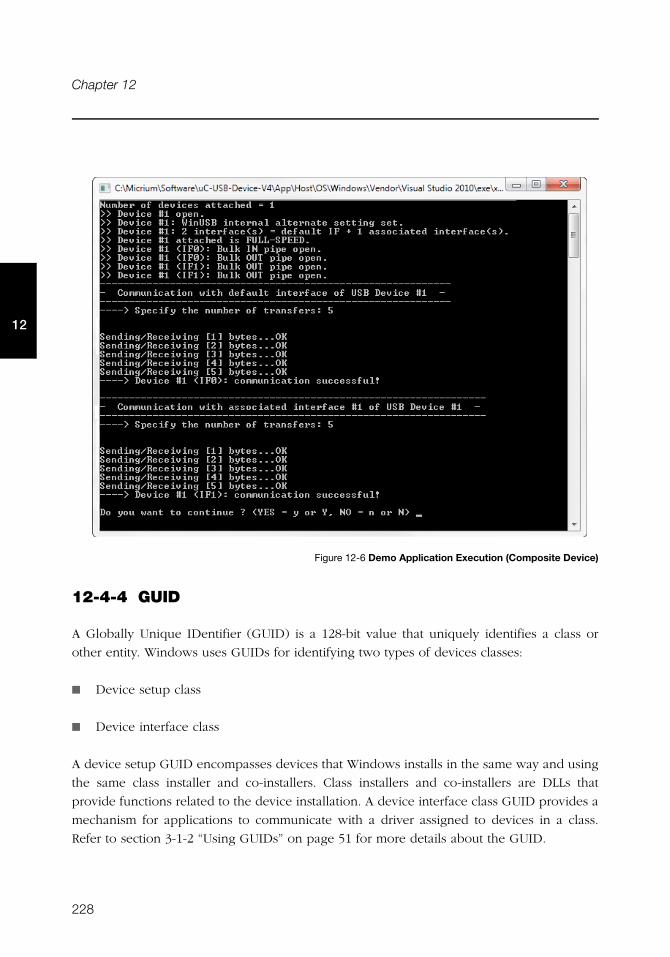
228
Chapter 12
12
Figure 12-6 Demo Application Execution (Composite Device)
12-4-4 GUID
A Globally Unique IDentifier (GUID) is a 128-bit value that uniquely identifies a class or
other entity. Windows uses GUIDs for identifying two types of devices classes:
■ Device setup class
■ Device interface class
A device setup GUID encompasses devices that Windows installs in the same way and using
the same class installer and co-installers. Class installers and co-installers are DLLs that
provide functions related to the device installation. A device interface class GUID provides a
mechanism for applications to communicate with a driver assigned to devices in a class.
Refer to section 3-1-2 “Using GUIDs” on page 51 for more details about the GUID.
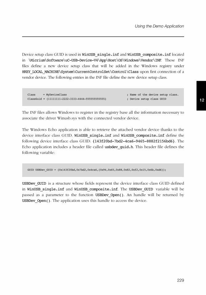
229
Using the Demo Application
12
Device setup class GUID is used in WinUSB_single.inf and WinUSB_composite.inf located
in \Micrium\Software\uC-USB-Device-V4\App\Host\OS\Windows\Vendor\INF. These INF
files define a new device setup class that will be added in the Windows registry under
HKEY_LOCAL_MACHINE\System\CurrentControlSet\Control\Class upon first connection of a
vendor device. The following entries in the INF file define the new device setup class.
The INF files allows Windows to register in the registry base all the information necessary to
associate the driver Winusb.sys with the connected vendor device.
The Windows Echo application is able to retrieve the attached vendor device thanks to the
device interface class GUID. WinUSB_single.inf and WinUSB_composite.inf define the
following device interface class GUID: {143f20bd-7bd2-4ca6-9465-8882f2156bd6}. The
Echo application includes a header file called usbdev_guid.h. This header file defines the
following variable:
USBDev_GUID is a structure whose fields represent the device interface class GUID defined
in WinUSB_single.inf and WinUSB_composite.inf. The USBDev_GUID variable will be
passed as a parameter to the function USBDev_Open(). An handle will be returned by
USBDev_Open(). The application uses this handle to access the device.
Class = MyDeviceClass ; Name of the device setup class.
ClassGuid = {11111111-2222-3333-4444-555555555555} ; Device setup class GUID
GUID USBDev_GUID = {0x143f20bd,0x7bd2,0x4ca6,{0x94,0x65,0x88,0x82,0xf2,0x15,0x6b,0xd6}};

230
Chapter 12
12
231
Chapter
13Debug and Trace
μC/USB-Device provides an option to enable debug traces to output transactional activity
via an output port of your choice such as the console or serial port. Debugging traces
allows you to see how the USB device stack behaves and is a useful troubleshooting tool
when trying to debug a problem. This chapter will show you the debug and trace tools
available in the USB device core as well as how to go about using them.
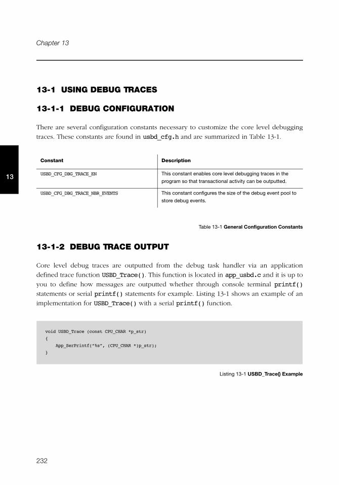
232
Chapter 13
13
13-1 USING DEBUG TRACES
13-1-1 DEBUG CONFIGURATION
There are several configuration constants necessary to customize the core level debugging
traces. These constants are found in usbd_cfg.h and are summarized in Table 13-1.
Table 13-1 General Configuration Constants
13-1-2 DEBUG TRACE OUTPUT
Core level debug traces are outputted from the debug task handler via an application
defined trace function USBD_Trace(). This function is located in app_usbd.c and it is up to
you to define how messages are outputted whether through console terminal printf()
statements or serial printf() statements for example. Listing 13-1 shows an example of an
implementation for USBD_Trace() with a serial printf() function.
Listing 13-1 USBD_Trace() Example
Constant Description
USBD_CFG_DBG_TRACE_EN This constant enables core level debugging traces in the
program so that transactional activity can be outputted.
USBD_CFG_DBG_TRACE_NBR_EVENTS This constant configures the size of the debug event pool to
store debug events.
void USBD_Trace (const CPU_CHAR *p_str)
{
App_SerPrintf(“%s”, (CPU_CHAR *)p_str);
}
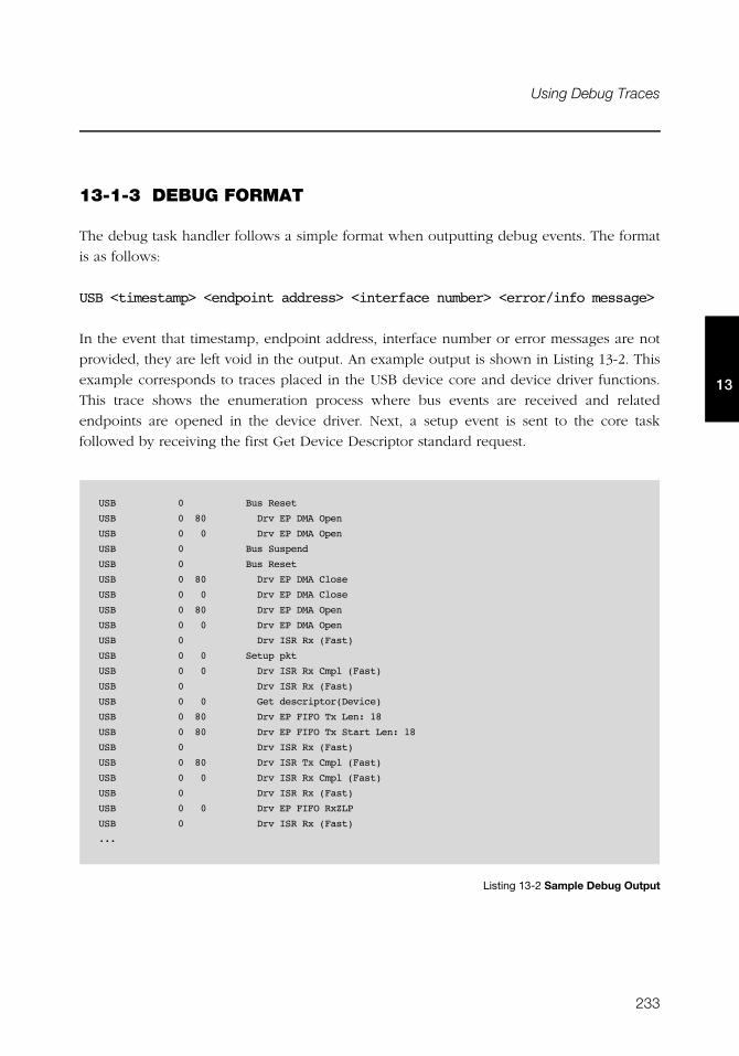
233
Using Debug Traces
13
13-1-3 DEBUG FORMAT
The debug task handler follows a simple format when outputting debug events. The format
is as follows:
USB <timestamp> <endpoint address> <interface number> <error/info message>
In the event that timestamp, endpoint address, interface number or error messages are not
provided, they are left void in the output. An example output is shown in Listing 13-2. This
example corresponds to traces placed in the USB device core and device driver functions.
This trace shows the enumeration process where bus events are received and related
endpoints are opened in the device driver. Next, a setup event is sent to the core task
followed by receiving the first Get Device Descriptor standard request.
Listing 13-2 Sample Debug Output
USB 0 Bus Reset
USB 0 80 Drv EP DMA Open
USB 0 0 Drv EP DMA Open
USB 0 Bus Suspend
USB 0 Bus Reset
USB 0 80 Drv EP DMA Close
USB 0 0 Drv EP DMA Close
USB 0 80 Drv EP DMA Open
USB 0 0 Drv EP DMA Open
USB 0 Drv ISR Rx (Fast)
USB 0 0 Setup pkt
USB 0 0 Drv ISR Rx Cmpl (Fast)
USB 0 Drv ISR Rx (Fast)
USB 0 0 Get descriptor(Device)
USB 0 80 Drv EP FIFO Tx Len: 18
USB 0 80 Drv EP FIFO Tx Start Len: 18
USB 0 Drv ISR Rx (Fast)
USB 0 80 Drv ISR Tx Cmpl (Fast)
USB 0 0 Drv ISR Rx Cmpl (Fast)
USB 0 Drv ISR Rx (Fast)
USB 0 0 Drv EP FIFO RxZLP
USB 0 Drv ISR Rx (Fast)
...
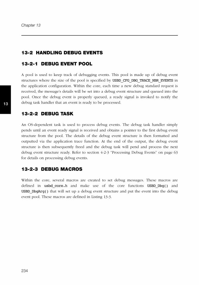
234
Chapter 13
13
13-2 HANDLING DEBUG EVENTS
13-2-1 DEBUG EVENT POOL
A pool is used to keep track of debugging events. This pool is made up of debug event
structures where the size of the pool is specified by USBD_CFG_DBG_TRACE_NBR_EVENTS in
the application configuration. Within the core, each time a new debug standard request is
received, the message’s details will be set into a debug event structure and queued into the
pool. Once the debug event is properly queued, a ready signal is invoked to notify the
debug task handler that an event is ready to be processed.
13-2-2 DEBUG TASK
An OS-dependent task is used to process debug events. The debug task handler simply
pends until an event ready signal is received and obtains a pointer to the first debug event
structure from the pool. The details of the debug event structure is then formatted and
outputted via the application trace function. At the end of the output, the debug event
structure is then subsequently freed and the debug task will pend and process the next
debug event structure ready. Refer to section 4-2-3 “Processing Debug Events” on page 63
for details on processing debug events.
13-2-3 DEBUG MACROS
Within the core, several macros are created to set debug messages. These macros are
defined in usbd_core.h and make use of the core functions USBD_Dbg() and
USBD_DbgArg() that will set up a debug event structure and put the event into the debug
event pool. These macros are defined in Listing 13-3.
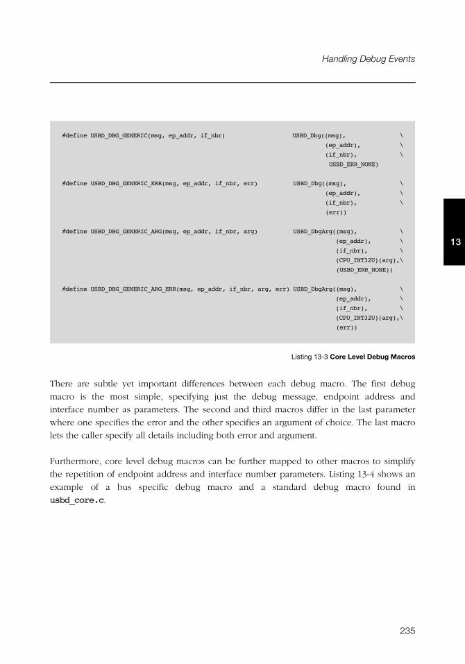
235
Handling Debug Events
13
Listing 13-3 Core Level Debug Macros
There are subtle yet important differences between each debug macro. The first debug
macro is the most simple, specifying just the debug message, endpoint address and
interface number as parameters. The second and third macros differ in the last parameter
where one specifies the error and the other specifies an argument of choice. The last macro
lets the caller specify all details including both error and argument.
Furthermore, core level debug macros can be further mapped to other macros to simplify
the repetition of endpoint address and interface number parameters. Listing 13-4 shows an
example of a bus specific debug macro and a standard debug macro found in
usbd_core.c.
#define USBD_DBG_GENERIC(msg, ep_addr, if_nbr) USBD_Dbg((msg), \
(ep_addr), \
(if_nbr), \
USBD_ERR_NONE)
#define USBD_DBG_GENERIC_ERR(msg, ep_addr, if_nbr, err) USBD_Dbg((msg), \
(ep_addr), \
(if_nbr), \
(err))
#define USBD_DBG_GENERIC_ARG(msg, ep_addr, if_nbr, arg) USBD_DbgArg((msg), \
(ep_addr), \
(if_nbr), \
(CPU_INT32U)(arg),\
(USBD_ERR_NONE))
#define USBD_DBG_GENERIC_ARG_ERR(msg, ep_addr, if_nbr, arg, err) USBD_DbgArg((msg), \
(ep_addr), \
(if_nbr), \
(CPU_INT32U)(arg),\
(err))
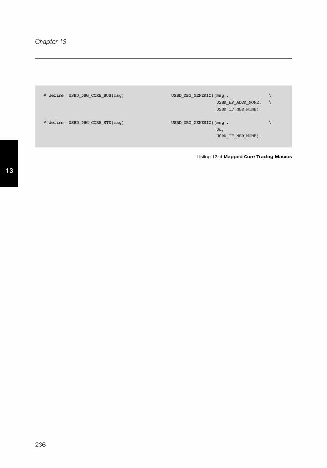
236
Chapter 13
13
Listing 13-4 Mapped Core Tracing Macros
# define USBD_DBG_CORE_BUS(msg) USBD_DBG_GENERIC((msg), \
USBD_EP_ADDR_NONE, \
USBD_IF_NBR_NONE)
# define USBD_DBG_CORE_STD(msg) USBD_DBG_GENERIC((msg), \
0u,
USBD_IF_NBR_NONE)
237
Chapter
14Porting μC/USB-Device to your RTOS
μC/USB-Device requires a Real-Time Operating System (RTOS). In order to make it usable
with nearly any RTOS available on the market, it has been designed to be easily portable.
Micriμm provides ports for both μC/OS-II and μC/OS-III and recommends using one of
these RTOS. In case you need to use another RTOS, this chapter will explain you how to
port μC/USB-Device to your RTOS.
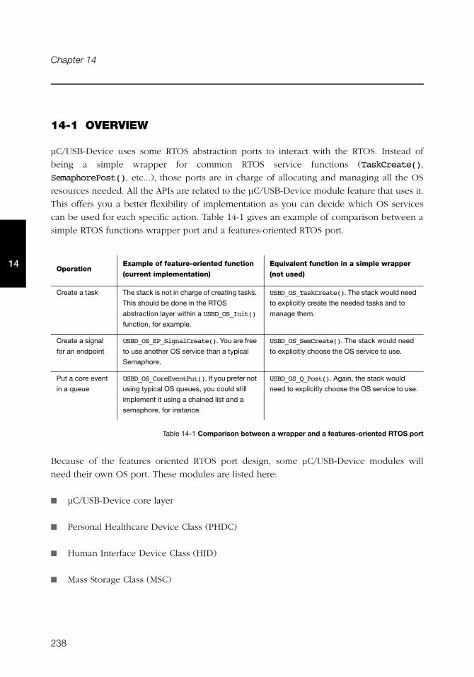
238
Chapter 14
14
14-1 OVERVIEW
μC/USB-Device uses some RTOS abstraction ports to interact with the RTOS. Instead of
being a simple wrapper for common RTOS service functions (TaskCreate(),
SemaphorePost(), etc...), those ports are in charge of allocating and managing all the OS
resources needed. All the APIs are related to the μC/USB-Device module feature that uses it.
This offers you a better flexibility of implementation as you can decide which OS services
can be used for each specific action. Table 14-1 gives an example of comparison between a
simple RTOS functions wrapper port and a features-oriented RTOS port.
Table 14-1 Comparison between a wrapper and a features-oriented RTOS port
Because of the features oriented RTOS port design, some μC/USB-Device modules will
need their own OS port. These modules are listed here:
■ μC/USB-Device core layer
■ Personal Healthcare Device Class (PHDC)
■ Human Interface Device Class (HID)
■ Mass Storage Class (MSC)
OperationExample of feature-oriented function
(current implementation)
Equivalent function in a simple wrapper
(not used)
Create a task The stack is not in charge of creating tasks.
This should be done in the RTOS
abstraction layer within a USBD_OS_Init()
function, for example.
USBD_OS_TaskCreate(). The stack would need
to explicitly create the needed tasks and to
manage them.
Create a signal
for an endpoint
USBD_OS_EP_SignalCreate(). You are free
to use another OS service than a typical
Semaphore.
USBD_OS_SemCreate(). The stack would need
to explicitly choose the OS service to use.
Put a core event
in a queue
USBD_OS_CoreEventPut(). If you prefer not
using typical OS queues, you could still
implement it using a chained list and a
semaphore, for instance.
USBD_OS_Q_Post(). Again, the stack would
need to explicitly choose the OS service to use.
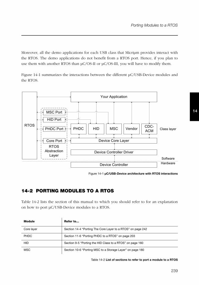
239
Porting Modules to a RTOS
14
Moreover, all the demo applications for each USB class that Micriμm provides interact with
the RTOS. The demo applications do not benefit from a RTOS port. Hence, if you plan to
use them with another RTOS than μC/OS-II or μC/OS-III, you will have to modify them.
Figure 14-1 summarizes the interactions between the different μC/USB-Device modules and
the RTOS.
Figure 14-1 μC/USB-Device architecture with RTOS interactions
14-2 PORTING MODULES TO A RTOS
Table 14-2 lists the section of this manual to which you should refer to for an explanation
on how to port μC/USB-Device modules to a RTOS.
Table 14-2 List of sections to refer to port a module to a RTOS
Module Refer to...
Core layer Section 14-4 “Porting The Core Layer to a RTOS” on page 242
PHDC Section 11-6 “Porting PHDC to a RTOS” on page 203
HID Section 9-5 “Porting the HID Class to a RTOS” on page 160
MSC Section 10-6 “Porting MSC to a Storage Layer” on page 180
� $�� #+� ����� �
� $�� #+� ����� �#���$ �
������� )��%���
� $�� #+�� #-�5 �
+�+,�+3 %���+)���)�+
4���
=��#����������
4����7'�������
-�5 �
+�� #����
�)�+#����
)��#����
�+#����
+��''#��5 �
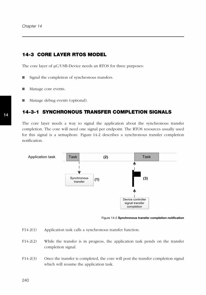
240
Chapter 14
14
14-3 CORE LAYER RTOS MODEL
The core layer of μC/USB-Device needs an RTOS for three purposes:
■ Signal the completion of synchronous transfers.
■ Manage core events.
■ Manage debug events (optional).
14-3-1 SYNCHRONOUS TRANSFER COMPLETION SIGNALS
The core layer needs a way to signal the application about the synchronous transfer
completion. The core will need one signal per endpoint. The RTOS resources usually used
for this signal is a semaphore. Figure 14-2 describes a synchronous transfer completion
notification.
Figure 14-2 Synchronous transfer completion notification
F14-2(1) Application task calls a synchronous transfer function.
F14-2(2) While the transfer is in progress, the application task pends on the transfer
completion signal.
F14-2(3) Once the transfer is completed, the core will post the transfer completion signal
which will resume the application task.
/�0
/�0
� $�� #�� ����� �#'�& ��#��� '� �#����� ���
/ 0
���������� #��'1 ��'1 ��'1
�5 �0�� �'#��� '� �
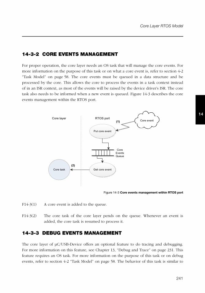
241
Core Layer RTOS Model
14
14-3-2 CORE EVENTS MANAGEMENT
For proper operation, the core layer needs an OS task that will manage the core events. For
more information on the purpose of this task or on what a core event is, refer to section 4-2
“Task Model” on page 58. The core events must be queued in a data structure and be
processed by the core. This allows the core to process the events in a task context instead
of in an ISR context, as most of the events will be raised by the device driver’s ISR. The core
task also needs to be informed when a new event is queued. Figure 14-3 describes the core
events management within the RTOS port.
Figure 14-3 Core events management within RTOS port
F14-3(1) A core event is added to the queue.
F14-3(2) The core task of the core layer pends on the queue. Whenever an event is
added, the core task is resumed to process it.
14-3-3 DEBUG EVENTS MANAGEMENT
The core layer of μC/USB-Device offers an optional feature to do tracing and debugging.
For more information on this feature, see Chapter 13, “Debug and Trace” on page 231. This
feature requires an OS task. For more information on the purpose of this task or on debug
events, refer to section 4-2 “Task Model” on page 58. The behavior of this task is similar to
/�0
/�0
+�� #�$ �'>
��#��� # $ �
+�� ��'1 ? �#��� # $ �
4���#����+�� #��5 �+�� # $ �
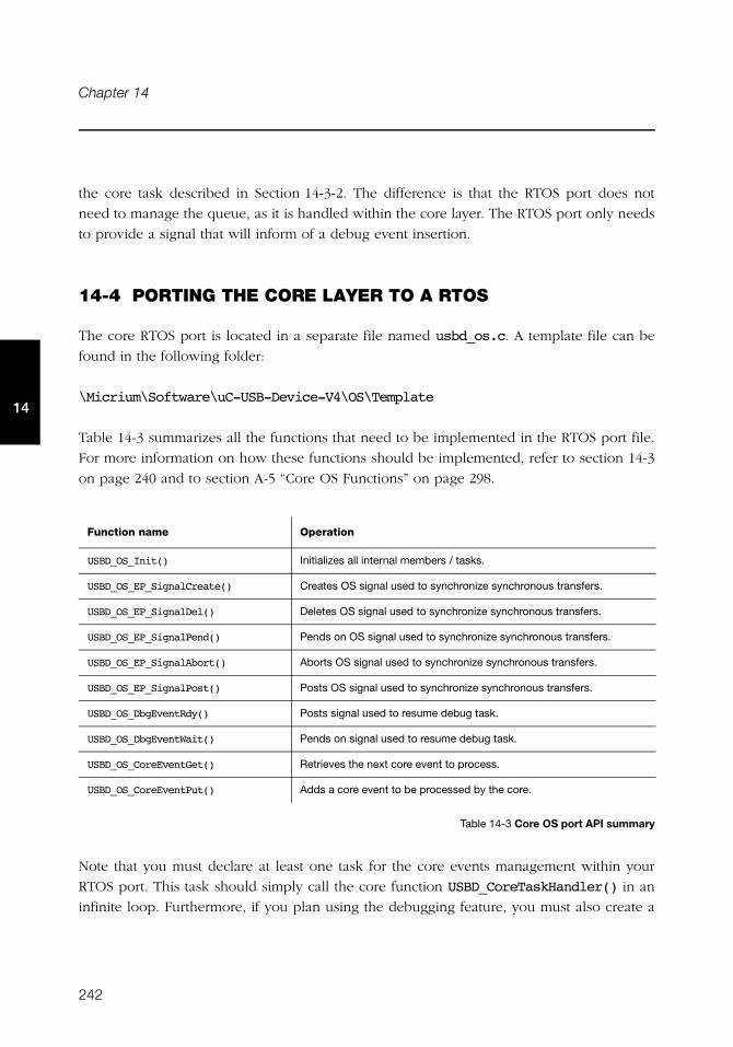
242
Chapter 14
14
the core task described in Section 14-3-2. The difference is that the RTOS port does not
need to manage the queue, as it is handled within the core layer. The RTOS port only needs
to provide a signal that will inform of a debug event insertion.
14-4 PORTING THE CORE LAYER TO A RTOS
The core RTOS port is located in a separate file named usbd_os.c. A template file can be
found in the following folder:
\Micrium\Software\uC-USB-Device-V4\OS\Template
Table 14-3 summarizes all the functions that need to be implemented in the RTOS port file.
For more information on how these functions should be implemented, refer to section 14-3
on page 240 and to section A-5 “Core OS Functions” on page 298.
Table 14-3 Core OS port API summary
Note that you must declare at least one task for the core events management within your
RTOS port. This task should simply call the core function USBD_CoreTaskHandler() in an
infinite loop. Furthermore, if you plan using the debugging feature, you must also create a
Function name Operation
USBD_OS_Init() Initializes all internal members / tasks.
USBD_OS_EP_SignalCreate() Creates OS signal used to synchronize synchronous transfers.
USBD_OS_EP_SignalDel() Deletes OS signal used to synchronize synchronous transfers.
USBD_OS_EP_SignalPend() Pends on OS signal used to synchronize synchronous transfers.
USBD_OS_EP_SignalAbort() Aborts OS signal used to synchronize synchronous transfers.
USBD_OS_EP_SignalPost() Posts OS signal used to synchronize synchronous transfers.
USBD_OS_DbgEventRdy() Posts signal used to resume debug task.
USBD_OS_DbgEventWait() Pends on signal used to resume debug task.
USBD_OS_CoreEventGet() Retrieves the next core event to process.
USBD_OS_CoreEventPut() Adds a core event to be processed by the core.
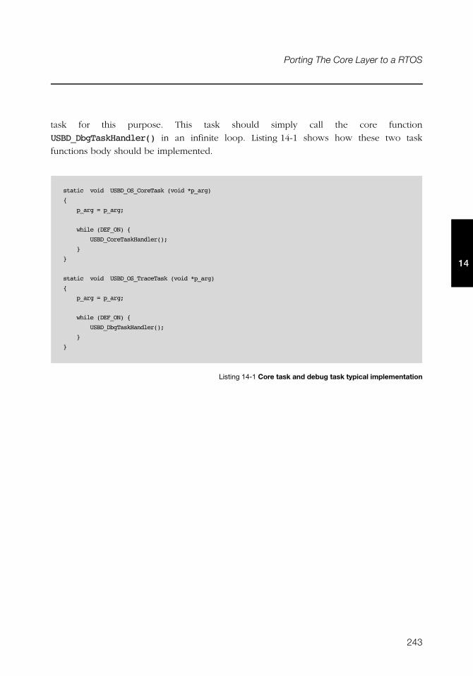
243
Porting The Core Layer to a RTOS
14
task for this purpose. This task should simply call the core function
USBD_DbgTaskHandler() in an infinite loop. Listing 14-1 shows how these two task
functions body should be implemented.
Listing 14-1 Core task and debug task typical implementation
static void USBD_OS_CoreTask (void *p_arg)
{
p_arg = p_arg;
while (DEF_ON) {
USBD_CoreTaskHandler();
}
}
static void USBD_OS_TraceTask (void *p_arg)
{
p_arg = p_arg;
while (DEF_ON) {
USBD_DbgTaskHandler();
}
}

244
Chapter 14
14
245
Appendix
ACore API Reference
This appendix provides a reference to the μC/USB-Device core layer API. The following
information is provided for each of the services:
■ A brief description
■ The function prototype
■ The filename of the source code
■ A description of the arguments passed to the function
■ A description of returned value(s)
■ Specific notes and warnings regarding use of the service
246
Appendix A
A
A-1 DEVICE FUNCTIONS
A-1-1 USBD_Init()
Initialize USB device stack. This function is called by the application exactly once. This
function initializes all the internal variables and modules used by the USB device stack.
FILES
usbd_core.h/usbd_core.c
PROTOTYPE
ARGUMENTS
p_err Pointer to variable that will receive the return error code from this function.
USBD_ERR_NONE
USBD_ERR_OS_INIT_FAIL
RETURNED VALUE
None.
CALLERS
Application.
NOTES / WARNINGS
USBD_Init() must be called:
■ Only once from a product’s application.
■ After product’s OS has been initialized
■ Before product’s application calls any USB device stack function(s).
static void USBD_Init (USBD_ERR *p_err);
247
A
A-1-2 USBD_DevStart()
Starts device stack. This function connects the device to the USB host.
FILES
usbd_core.h/usbd_core.c
PROTOTYPE
ARGUMENTS
dev_nbr Device number.
p_err Pointer to variable that will receive the return error code from this function.
USBD_ERR_NONE
USBD_ERR_DEV_INVALID_NBR
USBD_ERR_DEV_INVALID_STATE
RETURNED VALUE
None.
CALLERS
Application.
NOTES / WARNINGS
Device stack can be only started if the device is in either the USBD_DEV_STATE_NONE or
USB_DEV_STATE_INIT states.
void USBD_DevStart (CPU_INT08U dev_nbr,
USBD_ERR *p_err);
248
Appendix A
A
A-1-3 USBD_DevStop()
Stops device stack. This function disconnects the device from the USB host.
FILES
usbd_core.h/usbd_core.c
PROTOTYPE
ARGUMENTS
dev_nbr Device number.
p_err Pointer to variable that will receive the return error code from this function.
USBD_ERR_NONE
USBD_ERR_DEV_INVALID_NBR
USBD_ERR_DEV_INVALID_STATE
RETURNED VALUE
None.
CALLERS
Application.
NOTES / WARNINGS
None.
void USBD_DevStop (CPU_INT08U dev_nbr,
USBD_ERR *p_err);
249
A
A-1-4 USBD_DevGetState()
Gets current device state.
FILES
usbd_core.h/usbd_core.c
PROTOTYPE
ARGUMENTS
dev_nbr Device number.
p_err Pointer to variable that will receive the return error code from this function.
USBD_ERR_NONE
USBD_ERR_DEV_INVALID_NBR
RETURNED VALUE
Current device state, If no error(s).
USBD_DEV_STATE_NONE, otherwise.
CALLERS
USBD_EP_BulkRx()
USBD_EP_BulkRxAsync()
USBD_EP_BulkTx()
USBD_EP_BulkTxAsync()
USBD_EP_CtrlRx()
USBD_EP_CtrlRxStatus()
USBD_EP_CtrlTx()
USBD_EP_IntrRx()
USBD_DEV_STATE USBD_DevGetState (CPU_INT08U dev_nbr,
USBD_ERR *p_err);

250
Appendix A
A
USBD_EP_IntrRxAsync()
USBD_EP_IntrTx()
USBD_EP_IntrTxAsync()
NOTES / WARNINGS
None.
251
A
A-1-5 USBD_DevAdd()
Adds device to the stack.
FILES
usbd_cdc.h/usbd_cdc.c
PROTOTYPE
ARGUMENTS
p_dev_cfg Pointer to specific USB device configuration
p_bus_fnct Pointer to specific USB device configuration
p_drv_api Pointer to specific USB device driver API.
p_drv_cfg Pointer to specific USB device driver configuration.
p_bsp_api Pointer to specific USB device board-specific API.
p_err Pointer to variable that will receive the return error code from this function.
USBD_ERR_NONE
USBD_ERR_INVALID_ARG
USBD_ERR_NULL_PTR
USBD_ERR_DEV_ALLOC
USBD_ERR_EP_NONE_AVAIL
CPU_INT08U USBD_DevAdd (USBD_DEV_CFG *p_dev_cfg,
USBD_BUS_FNCTS *p_bus_fnct,
USBD_DRV_API *p_drv_api,
USBD_DRV_CFG *p_drv_cfg,
USBD_DRV_BSP_API *p_bsp_api,
USBD_ERR *p_err);
252
Appendix A
A
RETURNED VALUE
Device number, If no error(s).
USBD_DEV_NBR_NONE, otherwise.
CALLERS
Application.
NOTES / WARNINGS
None.
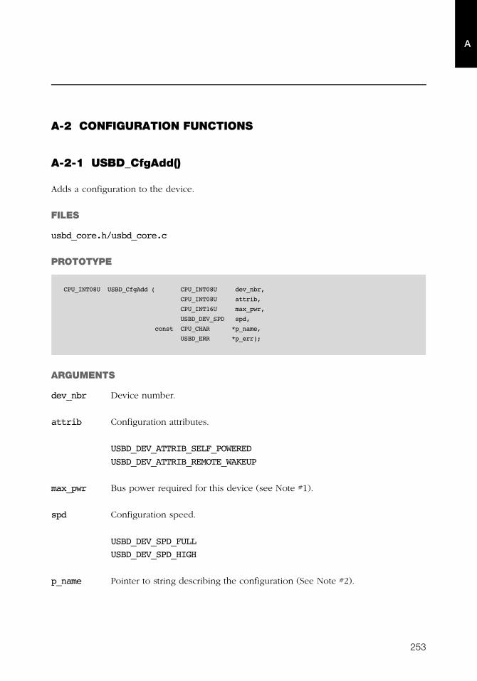
253
A
A-2 CONFIGURATION FUNCTIONS
A-2-1 USBD_CfgAdd()
Adds a configuration to the device.
FILES
usbd_core.h/usbd_core.c
PROTOTYPE
ARGUMENTS
dev_nbr Device number.
attrib Configuration attributes.
USBD_DEV_ATTRIB_SELF_POWERED
USBD_DEV_ATTRIB_REMOTE_WAKEUP
max_pwr Bus power required for this device (see Note #1).
spd Configuration speed.
USBD_DEV_SPD_FULL
USBD_DEV_SPD_HIGH
p_name Pointer to string describing the configuration (See Note #2).
CPU_INT08U USBD_CfgAdd ( CPU_INT08U dev_nbr,
CPU_INT08U attrib,
CPU_INT16U max_pwr,
USBD_DEV_SPD spd,
const CPU_CHAR *p_name,
USBD_ERR *p_err);
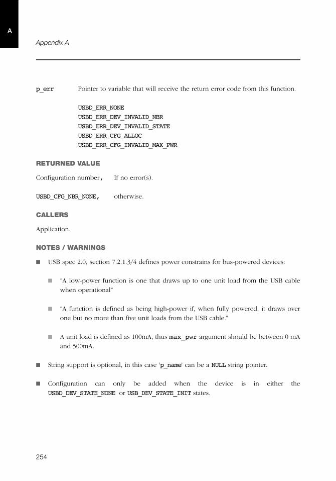
254
Appendix A
A
p_err Pointer to variable that will receive the return error code from this function.
USBD_ERR_NONE
USBD_ERR_DEV_INVALID_NBR
USBD_ERR_DEV_INVALID_STATE
USBD_ERR_CFG_ALLOC
USBD_ERR_CFG_INVALID_MAX_PWR
RETURNED VALUE
Configuration number, If no error(s).
USBD_CFG_NBR_NONE, otherwise.
CALLERS
Application.
NOTES / WARNINGS
■ USB spec 2.0, section 7.2.1.3/4 defines power constrains for bus-powered devices:
■ “A low-power function is one that draws up to one unit load from the USB cable
when operational”
■ “A function is defined as being high-power if, when fully powered, it draws over
one but no more than five unit loads from the USB cable.”
■ A unit load is defined as 100mA, thus max_pwr argument should be between 0 mA
and 500mA.
■ String support is optional, in this case 'p_name' can be a NULL string pointer.
■ Configuration can only be added when the device is in either the
USBD_DEV_STATE_NONE or USB_DEV_STATE_INIT states.
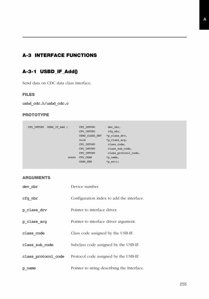
255
A
A-3 INTERFACE FUNCTIONS
A-3-1 USBD_IF_Add()
Send data on CDC data class interface.
FILES
usbd_cdc.h/usbd_cdc.c
PROTOTYPE
ARGUMENTS
dev_nbr Device number.
cfg_nbr Configuration index to add the interface.
p_class_drv Pointer to interface driver.
p_class_arg Pointer to interface driver argument.
class_code Class code assigned by the USB-IF.
class_sub_code Subclass code assigned by the USB-IF.
class_protocol_code Protocol code assigned by the USB-IF.
p_name Pointer to string describing the Interface.
CPU_INT08U USBD_IF_Add ( CPU_INT08U dev_nbr,
CPU_INT08U cfg_nbr,
USBD_CLASS_DRV *p_class_drv,
void *p_class_arg,
CPU_INT08U class_code,
CPU_INT08U class_sub_code,
CPU_INT08U class_protocol_code,
const CPU_CHAR *p_name,
USBD_ERR *p_err);
256
Appendix A
A
p_err Pointer to variable that will receive the return error code from this function.
USBD_ERR_NONE
USBD_ERR_INVALID_ARG
USBD_ERR_NULL_PTR
USBD_ERR_DEV_INVALID_NBR
USBD_ERR_DEV_INVALID_STATE
USBD_ERR_CFG_INVALID_NBR
USBD_ERR_IF_ALLOC
USBD_ERR_IF_ALT_ALLOC
RETURNED VALUE
None.
CALLERS
USB Class drivers.
NOTES / WARNINGS
Interface number, If no error(s).
USBD_IF_NBR_NONE, otherwise.
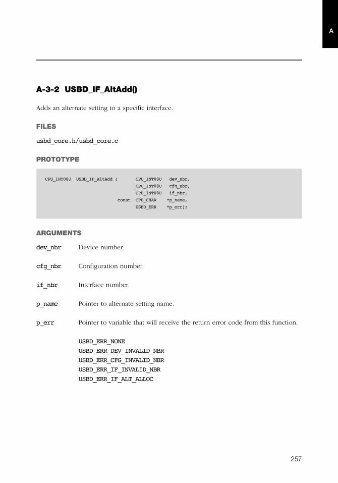
257
A
A-3-2 USBD_IF_AltAdd()
Adds an alternate setting to a specific interface.
FILES
usbd_core.h/usbd_core.c
PROTOTYPE
ARGUMENTS
dev_nbr Device number.
cfg_nbr Configuration number.
if_nbr Interface number.
p_name Pointer to alternate setting name.
p_err Pointer to variable that will receive the return error code from this function.
USBD_ERR_NONE
USBD_ERR_DEV_INVALID_NBR
USBD_ERR_CFG_INVALID_NBR
USBD_ERR_IF_INVALID_NBR
USBD_ERR_IF_ALT_ALLOC
CPU_INT08U USBD_IF_AltAdd ( CPU_INT08U dev_nbr,
CPU_INT08U cfg_nbr,
CPU_INT08U if_nbr,
const CPU_CHAR *p_name,
USBD_ERR *p_err);
258
Appendix A
A
RETURNED VALUE
Interface alternate setting number, if no errors.
USBD_IF_ALT_NBR_NONE, otherwise.
CALLERS
USB class drivers.
NOTES / WARNINGS
None.
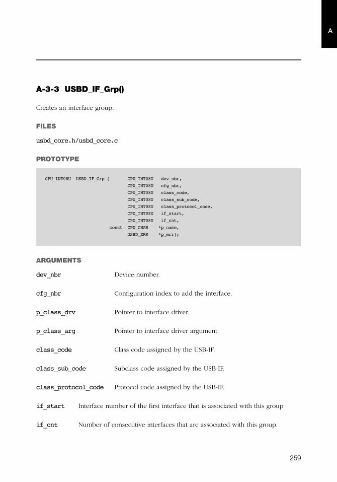
259
A
A-3-3 USBD_IF_Grp()
Creates an interface group.
FILES
usbd_core.h/usbd_core.c
PROTOTYPE
ARGUMENTS
dev_nbr Device number.
cfg_nbr Configuration index to add the interface.
p_class_drv Pointer to interface driver.
p_class_arg Pointer to interface driver argument.
class_code Class code assigned by the USB-IF.
class_sub_code Subclass code assigned by the USB-IF.
class_protocol_code Protocol code assigned by the USB-IF.
if_start Interface number of the first interface that is associated with this group
if_cnt Number of consecutive interfaces that are associated with this group.
CPU_INT08U USBD_IF_Grp ( CPU_INT08U dev_nbr,
CPU_INT08U cfg_nbr,
CPU_INT08U class_code,
CPU_INT08U class_sub_code,
CPU_INT08U class_protocol_code,
CPU_INT08U if_start,
CPU_INT08U if_cnt,
const CPU_CHAR *p_name,
USBD_ERR *p_err);
260
Appendix A
A
p_err Pointer to variable that will receive the return error code from this function.
USBD_ERR_NONE
USBD_ERR_DEV_INVALID_NBR
USBD_ERR_CFG_INVALID_NBR
USBD_ERR_IF_INVALID_NBR
USBD_ERR_IF_GRP_NBR_IN_USE
USBD_ERR_IF_GRP_ALLOC
RETURNED VALUE
Interface group number, if no errors.
USBD_IF_GRP_NBR_NONE, otherwise.
CALLERS
USB class drivers.
NOTES / WARNINGS
None.
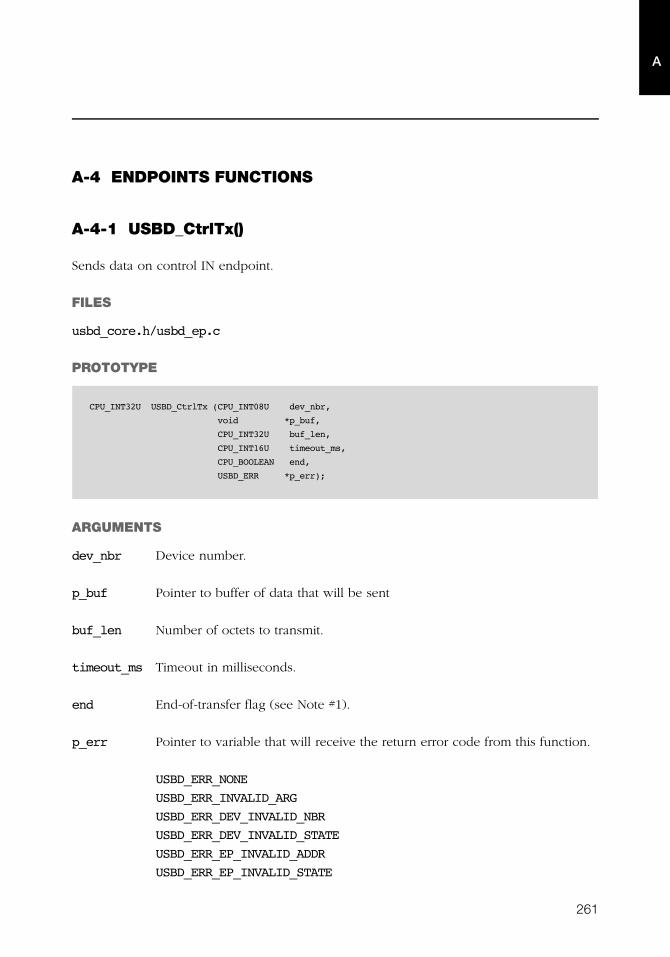
261
A
A-4 ENDPOINTS FUNCTIONS
A-4-1 USBD_CtrlTx()
Sends data on control IN endpoint.
FILES
usbd_core.h/usbd_ep.c
PROTOTYPE
ARGUMENTS
dev_nbr Device number.
p_buf Pointer to buffer of data that will be sent
buf_len Number of octets to transmit.
timeout_ms Timeout in milliseconds.
end End-of-transfer flag (see Note #1).
p_err Pointer to variable that will receive the return error code from this function.
USBD_ERR_NONE
USBD_ERR_INVALID_ARG
USBD_ERR_DEV_INVALID_NBR
USBD_ERR_DEV_INVALID_STATE
USBD_ERR_EP_INVALID_ADDR
USBD_ERR_EP_INVALID_STATE
CPU_INT32U USBD_CtrlTx (CPU_INT08U dev_nbr,
void *p_buf,
CPU_INT32U buf_len,
CPU_INT16U timeout_ms,
CPU_BOOLEAN end,
USBD_ERR *p_err);
262
Appendix A
A
USBD_ERR_EP_INVALID_TYPE
USBD_ERR_OS_TIMEOUT
USBD_ERR_OS_ABORT
USBD_ERR_OS_FAIL
RETURNED VALUE
Number of octets transmitted, if no errors.
0, otherwise.
CALLERS
USBD_DescWrReq()
USBD_DescWrStop()
USBD_StdReqDev()
USBD_StdReqEP()
USBD_StdReqIF()
USB device class drivers
NOTES / WARNINGS
■ If end-of-transfer is set and transfer length is multiple of maximum packet size, a zero-
length packet is transferred to indicate a short transfer to the host.
■ This function can be only called from USB device class drivers during class specific
setup request callbacks.
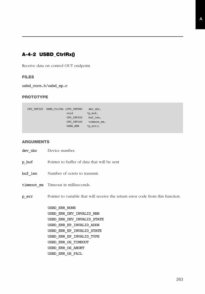
263
A
A-4-2 USBD_CtrlRx()
Receive data on control OUT endpoint.
FILES
usbd_core.h/usbd_ep.c
PROTOTYPE
ARGUMENTS
dev_nbr Device number.
p_buf Pointer to buffer of data that will be sent
buf_len Number of octets to transmit.
timeout_ms Timeout in milliseconds.
p_err Pointer to variable that will receive the return error code from this function.
USBD_ERR_NONE
USBD_ERR_DEV_INVALID_NBR
USBD_ERR_DEV_INVALID_STATE
USBD_ERR_EP_INVALID_ADDR
USBD_ERR_EP_INVALID_STATE
USBD_ERR_EP_INVALID_TYPE
USBD_ERR_OS_TIMEOUT
USBD_ERR_OS_ABORT
USBD_ERR_OS_FAIL
CPU_INT32U USBD_CtrlRx (CPU_INT08U dev_nbr,
void *p_buf,
CPU_INT32U buf_len,
CPU_INT16U timeout_ms,
USBD_ERR *p_err);
264
Appendix A
A
RETURNED VALUE
Number of octets received If no error(s).
0, otherwise.
CALLERS
USB device class drivers.
NOTES / WARNINGS
This function can be only called from USB device class drivers during class specific setup
request callbacks.
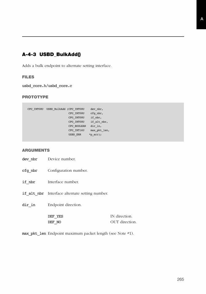
265
A
A-4-3 USBD_BulkAdd()
Adds a bulk endpoint to alternate setting interface.
FILES
usbd_core.h/usbd_core.c
PROTOTYPE
ARGUMENTS
dev_nbr Device number.
cfg_nbr Configuration number.
if_nbr Interface number.
if_alt_nbr Interface alternate setting number.
dir_in Endpoint direction.
DEF_YES IN direction.
DEF_NO OUT direction.
max_pkt_len Endpoint maximum packet length (see Note #1).
CPU_INT08U USBD_BulkAdd (CPU_INT08U dev_nbr,
CPU_INT08U cfg_nbr,
CPU_INT08U if_nbr,
CPU_INT08U if_alt_nbr,
CPU_BOOLEAN dir_in,
CPU_INT16U max_pkt_len,
USBD_ERR *p_err);
266
Appendix A
A
p_err Pointer to variable that will receive the return error code from this function.
USBD_ERR_NONE
USBD_ERR_INVALID_ARG
USBD_ERR_DEV_INVALID_NBR
USBD_ERR_CFG_INVALID_NBR
USBD_ERR_IF_INVALID_NBR
USBD_ERR_EP_NONE_AVAIL
USBD_ERR_EP_ALLOC
RETURNED VALUE
Endpoint address, if no error(s).
USBD_EP_ADDR_NONE, otherwise.
CALLERS
USB device class drivers.
NOTES / WARNINGS
If the max_pkt_len argument is '0', the stack will allocate the first available bulk endpoint
regardless its maximum packet size.
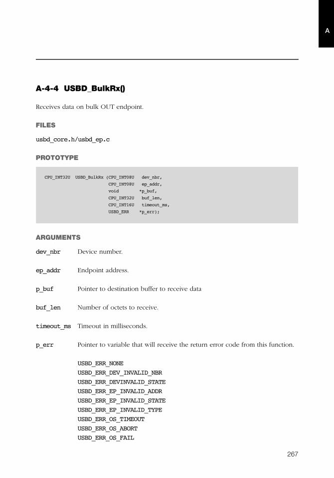
267
A
A-4-4 USBD_BulkRx()
Receives data on bulk OUT endpoint.
FILES
usbd_core.h/usbd_ep.c
PROTOTYPE
ARGUMENTS
dev_nbr Device number.
ep_addr Endpoint address.
p_buf Pointer to destination buffer to receive data
buf_len Number of octets to receive.
timeout_ms Timeout in milliseconds.
p_err Pointer to variable that will receive the return error code from this function.
USBD_ERR_NONE
USBD_ERR_DEV_INVALID_NBR
USBD_ERR_DEVINVALID_STATE
USBD_ERR_EP_INVALID_ADDR
USBD_ERR_EP_INVALID_STATE
USBD_ERR_EP_INVALID_TYPE
USBD_ERR_OS_TIMEOUT
USBD_ERR_OS_ABORT
USBD_ERR_OS_FAIL
CPU_INT32U USBD_BulkRx (CPU_INT08U dev_nbr,
CPU_INT08U ep_addr,
void *p_buf,
CPU_INT32U buf_len,
CPU_INT16U timeout_ms,
USBD_ERR *p_err);
268
Appendix A
A
RETURNED VALUE
Number of octets received, If no error(s).
0, otherwise.
CALLERS
USB device class drivers.
NOTES / WARNINGS
This function blocks until:
■ All data is received, or
■ An error occurred.
■ Transfer does not complete in the period specified by timeout_ms.
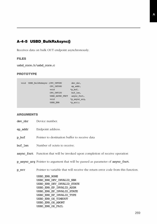
269
A
A-4-5 USBD_BulkRxAsync()
Receives data on bulk OUT endpoint asynchronously.
FILES
usbd_core.h/usbd_core.c
PROTOTYPE
ARGUMENTS
dev_nbr Device number.
ep_addr Endpoint address.
p_buf Pointer to destination buffer to receive data
buf_len Number of octets to receive.
async_fnct Function that will be invoked upon completion of receive operation
p_async_arg Pointer to argument that will be passed as parameter of async_fnct.
p_err Pointer to variable that will receive the return error code from this function.
USBD_ERR_NONEUSBD_ERR_DEV_INVALID_NBRUSBD_ERR_DEV_INVALID_STATEUSBD_ERR_EP_INVALID_ADDRUSBD_ERR_EP_INVALID_STATEUSBD_ERR_EP_INVALID_TYPEUSBD_ERR_OS_TIMEOUTUSBD_ERR_OS_ABORTUSBD_ERR_OS_FAIL
void USBD_BulkRxAsync (CPU_INT08U dev_nbr,
CPU_INT08U ep_addr,
void *p_buf,
CPU_INT32U buf_len,
USBD_ASYNC_FNCT async_fnct,
void *p_async_arg,
USBD_ERR *p_err);
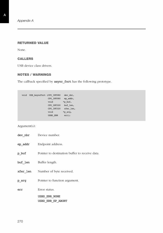
270
Appendix A
A
RETURNED VALUE
None.
CALLERS
USB device class drivers.
NOTES / WARNINGS
The callback specified by async_fnct has the following prototype.
Argument(s):
dev_nbr Device number.
ep_addr Endpoint address.
p_buf Pointer to destination buffer to receive data.
buf_len Buffer length.
xfer_len Number of byte received.
p_arg Pointer to function argument.
err Error status.
USBD_ERR_NONE
USBD_ERR_EP_ABORT
void USB_AsyncFnct (CPU_INT08U dev_nbr,
CPU_INT08U ep_addr,
void *p_buf,
CPU_INT32U buf_len,
CPU_INT32U xfer_len,
void *p_arg,
USBD_ERR err);
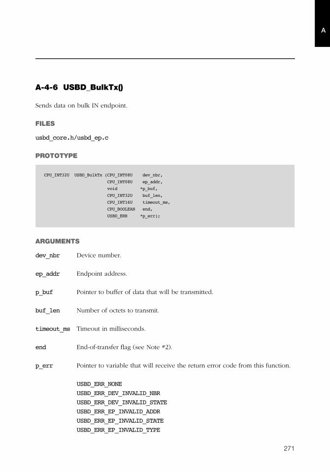
271
A
A-4-6 USBD_BulkTx()
Sends data on bulk IN endpoint.
FILES
usbd_core.h/usbd_ep.c
PROTOTYPE
ARGUMENTS
dev_nbr Device number.
ep_addr Endpoint address.
p_buf Pointer to buffer of data that will be transmitted.
buf_len Number of octets to transmit.
timeout_ms Timeout in milliseconds.
end End-of-transfer flag (see Note #2).
p_err Pointer to variable that will receive the return error code from this function.
USBD_ERR_NONE
USBD_ERR_DEV_INVALID_NBR
USBD_ERR_DEV_INVALID_STATE
USBD_ERR_EP_INVALID_ADDR
USBD_ERR_EP_INVALID_STATE
USBD_ERR_EP_INVALID_TYPE
CPU_INT32U USBD_BulkTx (CPU_INT08U dev_nbr,
CPU_INT08U ep_addr,
void *p_buf,
CPU_INT32U buf_len,
CPU_INT16U timeout_ms,
CPU_BOOLEAN end,
USBD_ERR *p_err);
272
Appendix A
A
USBD_ERR_OS_TIMEOUT
USBD_ERR_OS_ABORT
USBD_ERR_OS_FAIL
RETURNED VALUE
Number of octets transmitted, If no error(s).
0, otherwise.
CALLERS
USB device class drivers.
NOTES / WARNINGS
■ This function blocks until:
■ All data is transmitted, or
■ An error occurred.
■ Transfer does not complete in the period specified by timeout_ms.
■ If end-of-transfer is set and transfer length is multiple of maximum packet size,
a zero-length packet is transferred to indicate a short transfer to the host.
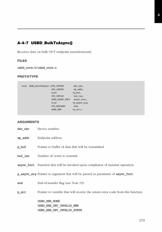
273
A
A-4-7 USBD_BulkTxAsync()
Receives data on bulk OUT endpoint asynchronously.
FILES
usbd_core.h/usbd_core.c
PROTOTYPE
ARGUMENTS
dev_nbr Device number.
ep_addr Endpoint address.
p_buf Pointer to buffer of data that will be transmitted
buf_len Number of octets to transmit.
async_fnct Function that will be invoked upon completion of transmit operation.
p_async_arg Pointer to argument that will be passed as parameter of async_fnct.
end End-of-transfer flag (see Note #2).
p_err Pointer to variable that will receive the return error code from this function.
USBD_ERR_NONE
USBD_ERR_DEV_INVALID_NBR
USBD_ERR_DEV_INVALID_STATE
void USBD_BulkTxAsync (CPU_INT08U dev_nbr,
CPU_INT08U ep_addr,
void *p_buf,
CPU_INT32U buf_len,
USBD_ASYNC_FNCT async_fnct,
void *p_async_arg,
CPU_BOOLEAN end,
USBD_ERR *p_err);
274
Appendix A
A
USBD_ERR_EP_INVALID_ADDR
USBD_ERR_EP_INVALID_STATE
USBD_ERR_EP_INVALID_TYPE
USBD_ERR_OS_TIMEOUT
USBD_ERR_OS_ABORT
USBD_ERR_OS_FAIL
RETURNED VALUE
None.
CALLERS
USB device class drivers.
NOTES / WARNINGS
■ The callback specified by async_fnct has the following prototype.
Argument(s):
dev_nbr Device number.
ep_addr Endpoint address.
p_buf Pointer to buffer of data that will be transmitted.
buf_len Buffer length.
xfer_len Number of byte transmitted.
p_arg Pointer to function argument.
void USB_AsyncFnct (CPU_INT08U dev_nbr,
CPU_INT08U ep_addr,
void *p_buf,
CPU_INT32U buf_len,
CPU_INT32U xfer_len,
void *p_arg,
USBD_ERR err);

275
A
err Error status.
USBD_ERR_NONE
USBD_ERR_EP_ABORT
■ If end-of-transfer is set and transfer length is multiple of maximum packet size, a zero-
length packet is transferred to indicate a short transfer to the host.
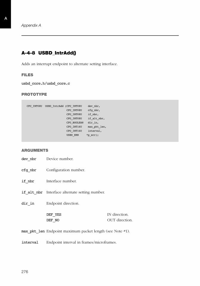
276
Appendix A
A
A-4-8 USBD_IntrAdd()
Adds an interrupt endpoint to alternate setting interface.
FILES
usbd_core.h/usbd_core.c
PROTOTYPE
ARGUMENTS
dev_nbr Device number.
cfg_nbr Configuration number.
if_nbr Interface number.
if_alt_nbr Interface alternate setting number.
dir_in Endpoint direction.
DEF_YES IN direction.
DEF_NO OUT direction.
max_pkt_len Endpoint maximum packet length (see Note #1).
interval Endpoint interval in frames/microframes.
CPU_INT08U USBD_IntrAdd (CPU_INT08U dev_nbr,
CPU_INT08U cfg_nbr,
CPU_INT08U if_nbr,
CPU_INT08U if_alt_nbr,
CPU_BOOLEAN dir_in,
CPU_INT16U max_pkt_len,
CPU_INT16U interval,
USBD_ERR *p_err);
277
A
p_err Pointer to variable that will receive the return error code from this function.
USBD_ERR_NONE
USBD_ERR_INVALID_ARG
USBD_ERR_DEV_INVALID_NBR
USBD_ERR_CFG_INVALID_NBR
USBD_ERR_IF_INVALID_NBR
USBD_ERR_EP_NONE_AVAIL
USBD_ERR_EP_ALLOC
RETURNED VALUE
Endpoint address, If no error(s).
USBD_EP_ADDR_NONE, otherwise.
CALLERS
USB device class drivers.
NOTES / WARNINGS
If the max_pkt_len argument is '0', the stack will allocate the first available interrupt
endpoint regardless its maximum packet size.
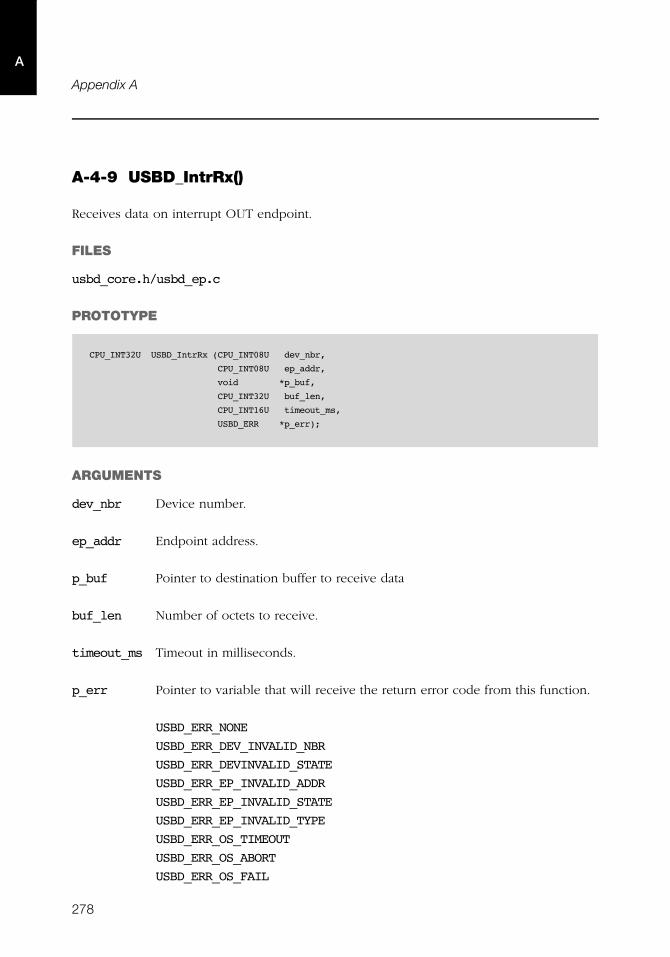
278
Appendix A
A
A-4-9 USBD_IntrRx()
Receives data on interrupt OUT endpoint.
FILES
usbd_core.h/usbd_ep.c
PROTOTYPE
ARGUMENTS
dev_nbr Device number.
ep_addr Endpoint address.
p_buf Pointer to destination buffer to receive data
buf_len Number of octets to receive.
timeout_ms Timeout in milliseconds.
p_err Pointer to variable that will receive the return error code from this function.
USBD_ERR_NONE
USBD_ERR_DEV_INVALID_NBR
USBD_ERR_DEVINVALID_STATE
USBD_ERR_EP_INVALID_ADDR
USBD_ERR_EP_INVALID_STATE
USBD_ERR_EP_INVALID_TYPE
USBD_ERR_OS_TIMEOUT
USBD_ERR_OS_ABORT
USBD_ERR_OS_FAIL
CPU_INT32U USBD_IntrRx (CPU_INT08U dev_nbr,
CPU_INT08U ep_addr,
void *p_buf,
CPU_INT32U buf_len,
CPU_INT16U timeout_ms,
USBD_ERR *p_err);
279
A
RETURNED VALUE
Number of octets received, If no error(s).
0, otherwise.
CALLERS
USB device class drivers.
NOTES / WARNINGS
This function blocks until:
■ All data is received, or
■ An error occurred.
■ Transfer does not complete in the period specified by timeout_ms.
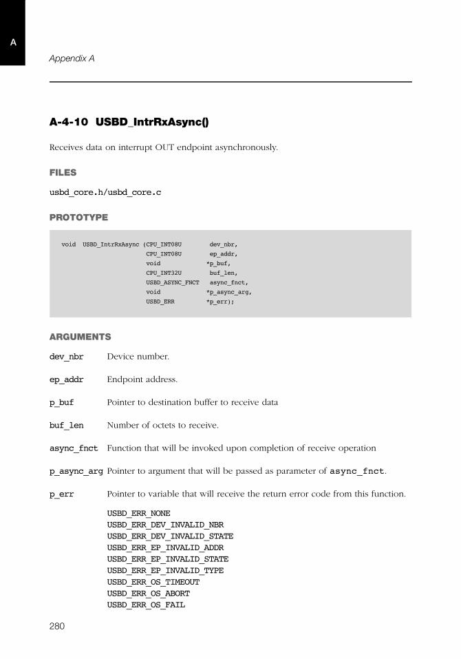
280
Appendix A
A
A-4-10 USBD_IntrRxAsync()
Receives data on interrupt OUT endpoint asynchronously.
FILES
usbd_core.h/usbd_core.c
PROTOTYPE
ARGUMENTS
dev_nbr Device number.
ep_addr Endpoint address.
p_buf Pointer to destination buffer to receive data
buf_len Number of octets to receive.
async_fnct Function that will be invoked upon completion of receive operation
p_async_arg Pointer to argument that will be passed as parameter of async_fnct.
p_err Pointer to variable that will receive the return error code from this function.
USBD_ERR_NONEUSBD_ERR_DEV_INVALID_NBRUSBD_ERR_DEV_INVALID_STATEUSBD_ERR_EP_INVALID_ADDRUSBD_ERR_EP_INVALID_STATEUSBD_ERR_EP_INVALID_TYPEUSBD_ERR_OS_TIMEOUTUSBD_ERR_OS_ABORTUSBD_ERR_OS_FAIL
void USBD_IntrRxAsync (CPU_INT08U dev_nbr,
CPU_INT08U ep_addr,
void *p_buf,
CPU_INT32U buf_len,
USBD_ASYNC_FNCT async_fnct,
void *p_async_arg,
USBD_ERR *p_err);
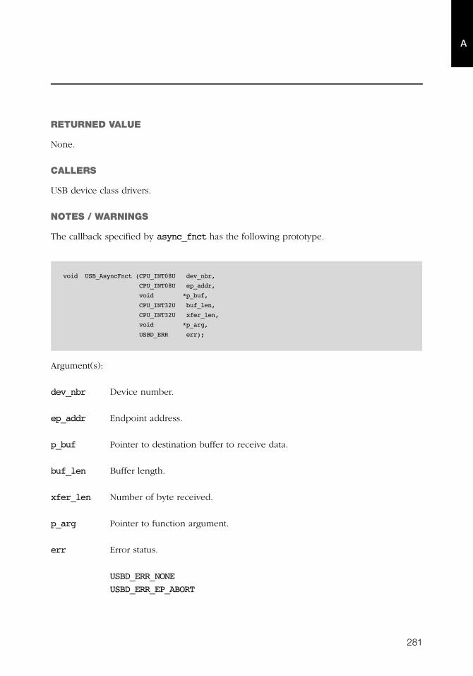
281
A
RETURNED VALUE
None.
CALLERS
USB device class drivers.
NOTES / WARNINGS
The callback specified by async_fnct has the following prototype.
Argument(s):
dev_nbr Device number.
ep_addr Endpoint address.
p_buf Pointer to destination buffer to receive data.
buf_len Buffer length.
xfer_len Number of byte received.
p_arg Pointer to function argument.
err Error status.
USBD_ERR_NONE
USBD_ERR_EP_ABORT
void USB_AsyncFnct (CPU_INT08U dev_nbr,
CPU_INT08U ep_addr,
void *p_buf,
CPU_INT32U buf_len,
CPU_INT32U xfer_len,
void *p_arg,
USBD_ERR err);
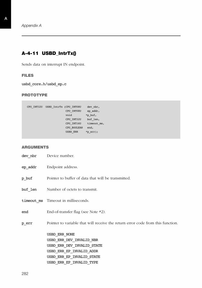
282
Appendix A
A
A-4-11 USBD_IntrTx()
Sends data on interrupt IN endpoint.
FILES
usbd_core.h/usbd_ep.c
PROTOTYPE
ARGUMENTS
dev_nbr Device number.
ep_addr Endpoint address.
p_buf Pointer to buffer of data that will be transmitted.
buf_len Number of octets to transmit.
timeout_ms Timeout in milliseconds.
end End-of-transfer flag (see Note #2).
p_err Pointer to variable that will receive the return error code from this function.
USBD_ERR_NONE
USBD_ERR_DEV_INVALID_NBR
USBD_ERR_DEV_INVALID_STATE
USBD_ERR_EP_INVALID_ADDR
USBD_ERR_EP_INVALID_STATE
USBD_ERR_EP_INVALID_TYPE
CPU_INT32U USBD_IntrTx (CPU_INT08U dev_nbr,
CPU_INT08U ep_addr,
void *p_buf,
CPU_INT32U buf_len,
CPU_INT16U timeout_ms,
CPU_BOOLEAN end,
USBD_ERR *p_err);
283
A
USBD_ERR_OS_TIMEOUT
USBD_ERR_OS_ABORT
USBD_ERR_OS_FAIL
RETURNED VALUE
Number of octets transmitted, If no error(s).
0, otherwise.
CALLERS
USB device class drivers.
NOTES / WARNINGS
■ This function blocks until:
■ All data is transmitted, or
■ An error occurred.
■ Transfer does not complete in the period specified by timeout_ms.
■ If end-of-transfer is set and transfer length is multiple of maximum packet size,
a zero-length packet is transferred to indicate a short transfer to the host.
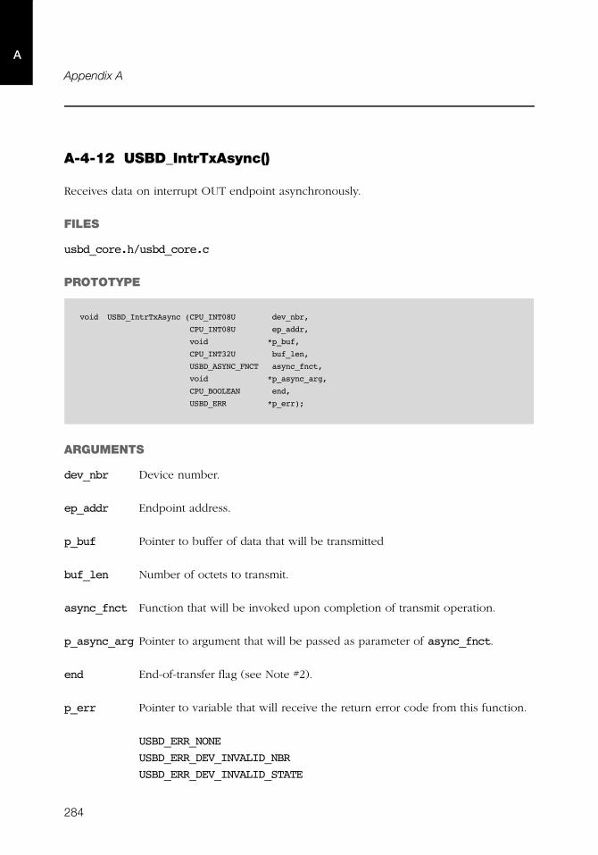
284
Appendix A
A
A-4-12 USBD_IntrTxAsync()
Receives data on interrupt OUT endpoint asynchronously.
FILES
usbd_core.h/usbd_core.c
PROTOTYPE
ARGUMENTS
dev_nbr Device number.
ep_addr Endpoint address.
p_buf Pointer to buffer of data that will be transmitted
buf_len Number of octets to transmit.
async_fnct Function that will be invoked upon completion of transmit operation.
p_async_arg Pointer to argument that will be passed as parameter of async_fnct.
end End-of-transfer flag (see Note #2).
p_err Pointer to variable that will receive the return error code from this function.
USBD_ERR_NONE
USBD_ERR_DEV_INVALID_NBR
USBD_ERR_DEV_INVALID_STATE
void USBD_IntrTxAsync (CPU_INT08U dev_nbr,
CPU_INT08U ep_addr,
void *p_buf,
CPU_INT32U buf_len,
USBD_ASYNC_FNCT async_fnct,
void *p_async_arg,
CPU_BOOLEAN end,
USBD_ERR *p_err);
285
A
USBD_ERR_EP_INVALID_ADDR
USBD_ERR_EP_INVALID_STATE
USBD_ERR_EP_INVALID_TYPE
USBD_ERR_OS_TIMEOUT
USBD_ERR_OS_ABORT
USBD_ERR_OS_FAIL
RETURNED VALUE
None.
CALLERS
USB device class drivers.
NOTES / WARNINGS
■ The callback specified by async_fnct has the following prototype.
Argument(s):
dev_nbr Device number.
ep_addr Endpoint address.
p_buf Pointer to buffer of data that will be transmitted.
buf_len Buffer length.
xfer_lenNumber of byte transmitted.
p_arg Pointer to function argument.
void USB_AsyncFnct (CPU_INT08U dev_nbr,
CPU_INT08U ep_addr,
void *p_buf,
CPU_INT32U buf_len,
CPU_INT32U xfer_len,
void *p_arg,
USBD_ERR err);

286
Appendix A
A
err Error status.
USBD_ERR_NONE
USBD_ERR_EP_ABORT
■ If end-of-transfer is set and transfer length is multiple of maximum packet size, a zero-
length packet is transferred to indicate a short transfer to the host.

287
A
A-4-13 USBD_EP_RxZLP()
Receives zero-length packet from the host.
FILES
usbd_core.h/usbd_ep.c
PROTOTYPE
ARGUMENTS
dev_nbr Pointer to USB device driver structure.
ep_addr Pointer to buffer of data that will be transmitted.
timeout_ms Timeout in milliseconds.
p_err Pointer to variable that will receive the return error code from this function.
USBD_ERR_OS_NONE
USBD_ERR_DEV_INVALID_NBR
USBD_ERR_EP_INVALID_ADDR
USBD_ERR_EP_INVALID_STATE
USBD_ERR_OS_TIMEOUT
USBD_ERR_OS_ABORT
USBD_ERR_OS_FAIL
RETURNED VALUE
None.
void USBD_EP_RxZLP (CPU_INT08U dev_nbr,
CPU_INT08U ep_addr,
CPU_INT16U timeout_ms,
USBD_ERR *p_err);

288
Appendix A
A
CALLERS
USBD_CtrlRx()
USBD_CtrlRxStatus()
USB device class drivers.
NOTES / WARNINGS
None.
289
A
A-4-14 USBD_EP_TxZLP()
Sends zero-length packet from the host.
FILES
usbd_core.h/usbd_ep.c
PROTOTYPE
ARGUMENTS
dev_nbr Pointer to USB device driver structure.
ep_addr Pointer to buffer of data that will be transmitted.
timeout_ms Timeout in milliseconds.
p_err Pointer to variable that will receive the return error code from this function.
USBD_ERR_OS_NONE
USBD_ERR_DEV_INVALID_NBR
USBD_ERR_EP_INVALID_ADDR
USBD_ERR_EP_INVALID_STATE
USBD_ERR_OS_TIMEOUT
USBD_ERR_OS_ABORT
USBD_ERR_OS_FAIL
RETURNED VALUE
None.
void USBD_EP_RxZLP (CPU_INT08U dev_nbr,
CPU_INT08U ep_addr,
CPU_INT16U timeout_ms,
USBD_ERR *p_err);

290
Appendix A
A
CALLERS
USBD_CtrlTxStatus()
USB device class drivers.
NOTES / WARNINGS
None.
291
A
A-4-15 USBD_EP_Abort()
Abort I/O transfer on endpoint.
FILES
usbd_core.h/usbd_ep.c
PROTOTYPE
ARGUMENTS
dev_nbr Device number.
ep_addr Endpoint address.
p_err Pointer to variable that will receive the return error code from this function.
USBD_ERR_NONE
USBD_ERR_DEV_INVALID_NBR
USBD_ERR_EP_INVALID_ADDR
USBD_ERR_EP_INVALID_STATE
USBD_ERR_EP_ABORT
USBD_ERR_EP_OS_FAIL
RETURNED VALUE
None.
CALLERS
USBD_EP_Stall()
USB device class drivers.
NOTES / WARNINGS
None.
void USBD_EP_Abort (CPU_INT08U dev_nbr,
CPU_INT08U ep_addr,
USBD_ERR *p_err);
292
Appendix A
A
A-4-16 USBD_EP_Stall()
Modify stall state condition on non-control endpoints.
FILES
usbd_core.h/usbd_ep.c
PROTOTYPE
ARGUMENTS
dev_nbr Device number.
ep_addr Line control change notification callback (see note #1).
state Endpoint stall state.
DEF_SET Set stall condition.
DEF_NO Clear stall condition.
p_err Pointer to variable that will receive the return error code from this function.
USBD_ERR_NONE
USBD_ERR_DEV_INVALID_ARG
USBD_ERR_EP_INVALID_ADDR
USBD_ERR_EP_INVALID_STATE
USBD_ERR_EP_STALL
USBD_ERR_EP_ABORT
USBD_ERR_OS_FAIL
RETURNED VALUE
None.
void USBD_EP_Stall (CPU_INT08U dev_nbr,
CPU_INT08U ep_addr,
CPU_BOOLEAN state,
USBD_ERR *p_err)

293
A
CALLERS
USBD_EP_Close()
USBD_StdReqEP()
USB device class drivers.
NOTES / WARNINGS
None.
294
Appendix A
A
A-4-17 USBD_EP_IsStalled()
Gets stall status of non-control endpoint
FILES
usbd_core.h/usbd_ep.c
PROTOTYPE
ARGUMENTS
dev_nbr Device number.
ep_addr Pointer to the structure where the current line coding will be stored.
p_err Pointer to variable that will receive the return error code from this function.
USBD_ERR_NONE
USBD_ERR_DEV_INVALID_ARG
USBD_ERR_EP_INVALID_ADDR
RETURNED VALUE
DEF_TRUE, if endpoint is stalled.
DEF_FALSE, otherwise.
CALLERS
USBD_StdReqEP()
USB device class drivers.
Application.
NOTES / WARNINGS
None.
CPU_BOOLEAN USBD_EP_IsStalled (CPU_INT08U dev_nbr,
CPU_INT08U ep_addr,
USBD_ERR *p_err);
295
A
A-4-18 USBD_EP_GetMaxPktSize()
Retrieves endpoint’s maximum packet size
FILES
usbd_core.h/usbd_ep.c
PROTOTYPE
ARGUMENTS
dev_nbr Device number.
ep_addr Endpoint address.
p_err Pointer to variable that will receive the return error code from this function.
USBD_ERR_NONE
USBD_ERR_DEV_INVALID_NBR
USBD_ERR_EP_INVALID_ADDR
USBD_ERR_EP_INVALID_STATE
RETURNED VALUE
Maximum packet size, If no error(s).
0, otherwise.
CALLERS
Application.
NOTES / WARNINGS
None.
CPU_INT16U USBD_EP_GetMaxPktSize (CPU_INT08U dev_nbr,
CPU_INT08U ep_addr,
USBD_ERR *p_err);
296
Appendix A
A
A-4-19 USBD_EP_GetMaxPhyNbr()
Get the maximum physical endpoint number.
FILES
usbd_core.h/usbd_ep.c
PROTOTYPE
ARGUMENTS
dev_nbr Device number.
RETURNED VALUE
Maximum physical endpoint number, If no error(s).
USBD_EP_PHY_NONE, otherwise.
CALLERS
USB device controllers drivers.
Application.
NOTES / WARNINGS
None.
CPU_INT08U USBD_EP_GetMaxPhyNbr (CPU_INT08U dev_nbr)
297
A
A-4-20 USBD_EP_GetMaxNbrOpen()
Retrieve maximum number of opened endpoints
FILES
usbd_core.h/usbd_ep.c
PROTOTYPE
ARGUMENTS
dev_nbr Device number.
RETURNED VALUE
Maximum number of opened endpoints, If no errors.
0, otherwise.
CALLERS
USB device controllers drivers.
Application.
NOTES / WARNINGS
None.
CPU_INT08U USBD_EP_GetMaxNbrOpen (CPU_INT08U dev_nbr);
298
Appendix A
A
A-5 CORE OS FUNCTIONS
A-5-1 USBD_OS_Init()
Initialize USB RTOS layer internal objects.
FILES
usbd_internal.h/usbd_os.c
PROTOTYPE
ARGUMENTS
p_err Pointer to variable that will receive the return error code from this function.
RETURNED VALUE
None.
CALLERS
USBD_Init()
IMPLEMENTATION GUIDELINES
■ The followings RTOS resources are required by the stack and should be allocated in
when this function is called.
■ One task for core and asynchronous events.
■ One queue that can hold up to USBD_CORE_EVENT_NBR_TOTAL events.
■ USBD_CFG_MAX_NBR_DEV x USBD_CFG_MAX_NBR_EP_OPEN semaphores for endpoints
operations.
void USBD_OS_Init (USBD_ERR *p_err);

299
A
■ If tracing is enabled, a semaphore and a task to manage debug events allocation
and debug events processing respectively.
If any error happen, USBD_ERR_OS_INIT_FAIL should be assigned to p_err and the
function should return immediately. Otherwise, USBD_ERR_NONE should be assigned to
p_err.
300
Appendix A
A
A-5-2 USBD_CoreTaskHandler()
Process all core events and operations.
FILES
usbd_internal.h/usbd_core.c
PROTOTYPE
ARGUMENTS
None.
RETURNED VALUE
None.
CALLERS
USB RTOS layer.
IMPLEMENTATION GUIDELINES
Typically, the RTOS layer should create a shell task for core events. The primary purpose of
the shell task is to run USBD_CoreTaskHandler().
void USBD_CoreTaskHandler (void);
301
A
A-5-3 USBD_DbgTaskHandler()
Process all pending debug events generated by the core.
FILES
usbd_internal.h/usbd_core.c
PROTOTYPE
ARGUMENTS
None.
RETURNED VALUE
None.
CALLERS
USB RTOS layer.
IMPLEMENTATION GUIDELINES
■ Typically, the RTOS layer code should create a shell task to process debug events
generated by the core. The primary purpose of the shell task is to run
USBD_DbgTaskHandler().
■ This function is only present in the code if trace option is enabled in the stack.
void USBD_DbgTaskHandler (void);
302
Appendix A
A
A-5-4 USBD_OS_EP_SignalCreate()
Creates a signal/semaphore for endpoints operations.
FILES
usbd_internal.h/usbd_os.c
PROTOTYPE
ARGUMENTS
dev_nbr Device number.
ep_ix Endpoint index.
p_err Pointer to variable that will receive the return error code from this function.
RETURNED VALUE
None.
CALLERS
Endpoints open functions.
IMPLEMENTATION GUIDELINES
■ The purpose of this function is to allocate a signal or a semaphore for the specified
endpoint.
void USBD_OS_EP_SignalCreate (CPU_INT08U dev_nbr,
CPU_INT08U ep_ix,
USBD_ERR *p_err);
303
A
■ Typically, the RTOS layer code should create a two-dimensional array to store the
signals/semaphores handlers. The dev_nbr and ep_ix are used to index this array.
■ dev_nbr ranges between 0 and USBD_CFG_MAX_NBR_DEV.
■ ep_ix ranges between 0 and USBD_CFG_MAX_NBR_EP_OPEN.
■ In case the creation fails, USBD_ERR_OS_SIGNAL_CREATE should be assigned to p_err.
Otherwise, USBD_ERR_NONE should be assigned to p_err.
304
Appendix A
A
A-5-5 USBD_OS_EP_SignalDel()
Deletes a signal/semaphore.
FILES
usbd_internal.h/usbd_os.c
PROTOTYPE
ARGUMENTS
dev_nbr Device number.
ep_ix Endpoint index.
RETURNED VALUE
None.
CALLERS
Endpoints close functions.
IMPLEMENTATION GUIDELINES
A call to this function should delete the signal / semaphore associated to the specified
endpoint.
void USBD_OS_EP_SignalDel (CPU_INT08U dev_nbr,
CPU_INT08U ep_ix);
305
A
A-5-6 USBD_OS_EP_SignalPend()
Waits for a signal/semaphore to become available.
FILES
usbd_internal.h/usbd_os.c
PROTOTYPE
ARGUMENTS
dev_nbr Device number.
ep_ix Endpoint index.
timeout_ms Timeout in milliseconds.
p_err Pointer to variable that will receive the return error code from this function.
RETURNED VALUE
None.
CALLERS
Endpoints Rx/Tx functions.
IMPLEMENTATION GUIDELINES
A call to this function should pend on the signal / semaphore associated to the specified
endpoint.
Table A-1 describes the error codes that should be assigned to p_err depending on the
operation result.
void USBD_OS_EP_SignalPend (CPU_INT08U dev_nbr,
CPU_INT08U ep_ix,
CPU_INT16U timeout_ms,
USBD_ERR *p_err);
306
Appendix A
A
Table A-1 p_err assignment in function of operation result.
Operation result Error code
No error. USBD_ERR_NONE
Pend timeout USBD_ERR_OS_TIMEOUT
Pend aborted USBD_ERR_OS_ABORT
Pend failed for any other reason USBD_ERR_OS_FAIL
307
A
A-5-7 USBD_OS_EP_SignalAbort()
Aborts any wait operation on signal/semaphore.
FILES
usbd_internal.h/usbd_os.c
PROTOTYPE
ARGUMENTS
dev_nbr Device number.
ep_ix Endpoint index.
p_err Pointer to variable that will receive the return error code from this function.
RETURNED VALUE
None.
CALLERS
Endpoints abort functions.
IMPLEMENTATION GUIDELINES
This function should abort all pend operations performed on the signal / semaphore
associated to the specified endpoint.
If any error happen, USBD_ERR_OS_FAIL should be assigned to p_err. Otherwise,
USBD_ERR_NONE should be assigned to p_err.
void USBD_OS_EP_SignalAbort (CPU_INT08U dev_nbr,
CPU_INT08U ep_ix,
USBD_ERR *p_err);
308
Appendix A
A
A-5-8 USBD_OS_EP_SignalPost()
Makes a signal/semaphore available.
FILES
usbd_internal.h/usbd_os.c
PROTOTYPE
ARGUMENTS
dev_nbr Device number.
ep_ix Endpoint index.
p_err Pointer to variable that will receive the return error code from this function.
RETURNED VALUE
None.
CALLERS
Endpoints transfer complete functions.
IMPLEMENTATION GUIDELINES
A call to this function should post the signal / semaphore associated to the specified
endpoint.
In case the post fail, USBD_ERR_OS_FAIL should be assigned to p_err. Otherwise,
USBD_ERR_NONE should be assigned to p_err.
void USBD_OS_EP_SignalPost (CPU_INT08U dev_nbr,
CPU_INT08U ep_ix,
USBD_ERR *p_err);
309
A
A-5-9 USBD_OS_CoreEventPut()
Queues a core event.
FILES
usbd_internal.h/usbd_os.c
PROTOTYPE
ARGUMENTS
p_event Pointer to core event.
RETURNED VALUE
None.
CALLERS
Endpoints and bus event handlers.
IMPLEMENTATION GUIDELINES
A call to this function should add the passed event to the core events queue.
void USBD_OS_CoreEventPut (void *p_event);
310
Appendix A
A
A-5-10 USBD_OS_CoreEventGet()
Wait until a core event is ready.
FILES
usbd_internal.h/usbd_os.c
PROTOTYPE
ARGUMENTS
timeout_ms Timeout in milliseconds.
p_err Pointer to variable that will receive the return error code from this function.
RETURNED VALUE
Pointer to core event, if no errors.
Null pointer, otherwise.
CALLERS
USBD_CoreTaskHandler()
IMPLEMENTATION GUIDELINES
A call to this function should block until an event is added to queue and return it.
Table A-1 describes the error codes that should be assigned to p_err depending on the
operation result.
void *USBD_OS_CoreEventGet (CPU_INT32U timeout_ms,
USBD_ERR *p_err);
311
A
A-5-11 USBD_OS_DbgEventRdy()
Signals debug event handler task.
FILES
usbd_internal.h/usbd_os.c
PROTOTYPE
ARGUMENTS
None.
RETURNED VALUE
None.
CALLERS
Debug functions.
IMPLEMENTATION GUIDELINES
A call to this function should post the signal / semaphore that resume the debug task.
void USBD_OS_DbgEventRdy (void);
312
Appendix A
A
A-5-12 USBD_OS_DbgEventWait ()
Waits until a trace event is available.
FILES
usbd_internal.h/usbd_os.c
PROTOTYPE
ARGUMENTS
None.
RETURNED VALUE
None.
CALLERS
USBD_DbgTaskHandler()
IMPLEMENTATION GUIDELINES
A call to this function should pend on the signal / semaphore that resume the debug task.
void USBD_OS_DbgEventWait (void);
313
A
A-6 DEVICE DRIVERS CALLBACKS FUNCTIONS
A-6-1 USBD_EP_RxCmpl()
Notifies the stack that an OUT transfer is completed.
FILES
usbd_core.h/usbd_ep.c
PROTOTYPE
ARGUMENTS
p_drv Pointer to device driver structure.
ep_log_nbr Endpoint logical number.
RETURNED VALUE
None.
CALLERS
USB device controller drivers ISR
NOTES / WARNINGS
None.
void USBD_EP_RxCmpl (USBD_DRV *p_drv,
CPU_INT08U ep_log_nbr);
314
Appendix A
A
A-6-2 USBD_EP_TxCmpl()
Notifies the stack that an IN transfer is completed.
FILES
usbd_core.h/usbd_ep.c
PROTOTYPE
ARGUMENTS
p_drv Pointer to device driver structure.
ep_log_nbr Endpoint logical number.
RETURNED VALUE
None.
CALLERS
USB device controller drivers ISR
NOTES / WARNINGS
None.
void USBD_EP_RxCmpl (USBD_DRV *p_drv,
CPU_INT08U ep_log_nbr);
315
A
A-6-3 USBD_EventConn()
Notifies the stack the device is connected to the host.
FILES
usbd_core.h/usbd_core.c
PROTOTYPE
ARGUMENTS
p_drv Pointer to device driver structure.
RETURNED VALUE
None.
CALLERS
USB device controller drivers ISR
NOTES / WARNINGS
None.
void USBD_EventConn (USBD_DRV *p_drv);
316
Appendix A
A
A-6-4 USBD_EventDisconn()
Notifies the stack the device is disconnect from the host..
FILES
usbd_core.h/usbd_core.c
PROTOTYPE
ARGUMENTS
p_drv Pointer to device driver structure.
RETURNED VALUE
None.
CALLERS
USB device controller drivers ISR
NOTES / WARNINGS
None.
void USBD_EventDisconn (USBD_DRV *p_drv);

317
A
A-6-5 USBD_EventReset()
Notifies the stack a reset event in the bus.
FILES
usbd_core.h/usbd_core.c
PROTOTYPE
ARGUMENTS
p_drv Pointer to device driver structure.
RETURNED VALUE
None.
CALLERS
USB device controller drivers ISR
NOTES / WARNINGS
None.
void USBD_EventReset(USBD_DRV *p_drv);
318
Appendix A
A
A-6-6 USBD_EventHS()
This function notifies the stack that a host is high speed capable.
FILES
usbd_core.h/usbd_core.c
PROTOTYPE
ARGUMENTS
p_drv Pointer to device driver structure.
RETURNED VALUE
None.
CALLERS
USB device controller drivers ISR
NOTES / WARNINGS
None.
void USBD_EventHS(USBD_DRV *p_drv);
319
A
A-6-7 USBD_EventSuspend()
Notifies the stack a suspend event in the bus.
FILES
usbd_core.h/usbd_core.c
PROTOTYPE
ARGUMENTS
p_drv Pointer to device driver structure.
RETURNED VALUE
None.
CALLERS
USB device controller drivers ISR
NOTES / WARNINGS
None.
void USBD_EventSuspend (USBD_DRV *p_drv);
320
Appendix A
A
A-6-8 USBD_EventResume()
Notifies the stack a resume event in the bus.
FILES
usbd_core.h/usbd_core.c
PROTOTYPE
ARGUMENTS
p_drv Pointer to device driver structure.
RETURNED VALUE
None.
CALLERS
USB device controller drivers ISR
NOTES / WARNINGS
None.
void USBD_EventResume (USBD_DRV *p_drv);
321
A
A-7 TRACE FUNCTIONS
A-7-1 USBD_Trace()
Outputs debug information from the core. Users must implement this function if trace
functionality is enabled (USBD_CFG_DBG_TRACE is defined to DEF_ENABLED).
FILES
usbd_core.h
PROTOTYPE
ARGUMENTS
p_drv Pointer to the string containing debug information.
RETURNED VALUE
None.
CALLERS
USB core debug task handler.
NOTES / WARNINGS
None.
void USBD_Trace (const CPU_CHAR *p_str);

322
Appendix A
A
323
Appendix
BDevice Controller Driver API Reference
This appendix provides a reference to the Device Controller Driver API. Each user-
accessible service is presented in alphabetical order. The following information is provided
for each of the services:
■ A brief description
■ The function prototype
■ The filename of the source code
■ A description of the arguments passed to the function
■ A description of returned value(s)
■ Specific notes and warnings regarding use of the service
324
Appendix BB
B-1 DEVICE DRIVER FUNCTIONS
B-1-1 USBD_DrvInit()
The first function within the Device Driver API is the device driver initialization/Init()
function. This function is called by USBD_DevStart() exactly once for each specific device
added by the application. If multiple instances of the same device are present on the
development board, then this function is called for each instance of the device. However,
applications should not try to add the same specific device more than once. If a device fails
to initialize, it is recommend debugging to find and correct the cause of failure.
Note: This function relies heavily on the implementation of several device board support
package (BSP) functions. See section B-2 “Device Driver BSP Functions” on page 350 for
more information on device BSP functions.
FILES
Every device driver’s usbd_drv.c
PROTOTYPE
Note that since every device driver function is accessed only by function pointer via the
device driver’s API structure, they do not need to be globally available and should therefore
be declared as ‘static’.
ARGUMENTS
p_drv Pointer to USB device driver structure.
p_err Pointer to variable that will receive the return error code from this function.
RETURNED VALUE
None.
static void USBD_DrvInit (USBD_DRV *p_drv
USBD_ERR *p_err);
325
B
CALLERS
USBD_DevInit() via 'p_drv_api->Init()'.
NOTES / WARNINGS
The Init() function generally performs the following operations, however, depending on
the device being initialized, functionality may need to be added or removed:
■ Configure clock gating to the USB device, configure all necessary I/O pins, and
configure the host interrupt controller. This is generally performed via the device’s BSP
function pointer, Init(), implemented in usbd_bsp.c (see section B-2-1
“USBD_BSP_Init()” on page 350).
■ Reset USB controller or USB controller registers.
■ Disable and clear pending interrupts (should already be cleared).
■ Set the device address to zero.
■ For DMA devices: Allocate memory for all necessary descriptors. This is performed via
calls to μC/LIB’s memory module. If memory allocation fails, set p_err to
USBD_ERR_ALLOC and return.
■ Set p_err to USBD_ERR_NONE if initialization proceeded as expected. Otherwise, set
p_err to an appropriate device error code.
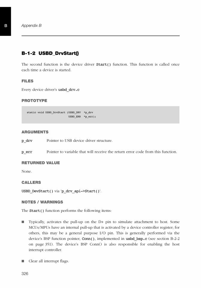
326
Appendix BB
B-1-2 USBD_DrvStart()
The second function is the device driver Start() function. This function is called once
each time a device is started.
FILES
Every device driver’s usbd_drv.c
PROTOTYPE
ARGUMENTS
p_drv Pointer to USB device driver structure.
p_err Pointer to variable that will receive the return error code from this function.
RETURNED VALUE
None.
CALLERS
USBD_DevStart() via 'p_drv_api->Start()'.
NOTES / WARNINGS
The Start() function performs the following items:
■ Typically, activates the pull-up on the D+ pin to simulate attachment to host. Some
MCUs/MPUs have an internal pull-up that is activated by a device controller register; for
others, this may be a general purpose I/O pin. This is generally performed via the
device’s BSP function pointer, Conn(), implemented in usbd_bsp.c (see section B-2-2
on page 351). The device’s BSP Conn() is also responsible for enabling the host
interrupt controller.
■ Clear all interrupt flags.
static void USBD_DrvStart (USBD_DRV *p_drv
USBD_ERR *p_err);
327
B
■ Locally enable interrupts on the hardware device. The host interrupt controller should
have already been configured within the device driver Init() function.
■ Enable the controller.
■ Set p_err equal to USBD_ERR_NONE if no errors have occurred. Otherwise, set p_err to
an appropriate device error code.

328
Appendix BB
B-1-3 USBD_DrvStop()
The next function within the device API structure is the device Stop() function. This
function is called once each time a device is stopped.
FILES
Every device driver’s usbd_drv.c
PROTOTYPE
ARGUMENTS
p_drv Pointer to USB device driver structure.
RETURNED VALUE
None.
CALLERS
USBD_DevStop() via 'p_drv_api->Stop()'.
NOTES / WARNINGS
Typically, the Stop() function performs the following operations:
■ Disable the controller.
■ Clear and locally disable interrupts on the hardware device.
■ Disconnect from the USB host (e.g, reset the pull-up on the D+ pin). This is generally
performed via the device’s BSP function pointer, Disconn(), implemented in
usbd_bsp.c (see section B-2-3 on page 352).
static void USBD_DrvStop (USBD_DRV *p_drv);
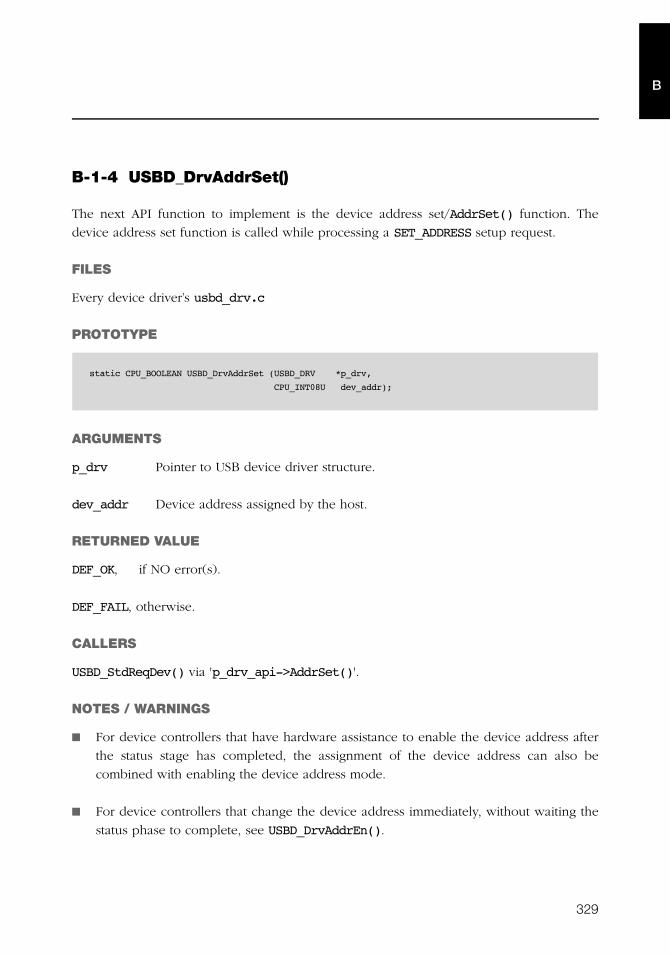
329
B
B-1-4 USBD_DrvAddrSet()
The next API function to implement is the device address set/AddrSet() function. The
device address set function is called while processing a SET_ADDRESS setup request.
FILES
Every device driver’s usbd_drv.c
PROTOTYPE
ARGUMENTS
p_drv Pointer to USB device driver structure.
dev_addr Device address assigned by the host.
RETURNED VALUE
DEF_OK, if NO error(s).
DEF_FAIL, otherwise.
CALLERS
USBD_StdReqDev() via 'p_drv_api->AddrSet()'.
NOTES / WARNINGS
■ For device controllers that have hardware assistance to enable the device address after
the status stage has completed, the assignment of the device address can also be
combined with enabling the device address mode.
■ For device controllers that change the device address immediately, without waiting the
status phase to complete, see USBD_DrvAddrEn().
static CPU_BOOLEAN USBD_DrvAddrSet (USBD_DRV *p_drv,
CPU_INT08U dev_addr);
330
Appendix BB
B-1-5 USBD_DrvAddrEn()
The next function in the device API structure is the device address enable/AddrEn()
function.
FILES
Every device driver’s usbd_drv.c
PROTOTYPE
ARGUMENTS
p_drv Pointer to USB device driver structure.
dev_addr Device address assigned by the host.
RETURNED VALUE
None.
CALLERS
USBD_StdReqHandler() via 'p_drv_api->AddrEn()'.
NOTES / WARNINGS
■ For device controllers that have hardware assistance to enable the device address after
the status stage has completed, no operation needs to be performed.
■ For device controllers that change the device address immediately, without waiting the
status phase to complete, the device address must be set and enabled.
static CPU_BOOLEAN USBD_DrvAddrEn (USBD_DRV *p_drv
CPU_INT08U dev_addr);
331
B
B-1-6 USBD_DrvCfgSet()
Bring device into configured state.
FILES
Every device driver’s usbd_drv.c
PROTOTYPE
ARGUMENTS
p_drv Pointer to USB device driver structure.
cfg_val Configuration value.
RETURNED VALUE
DEF_OK, if NO error(s).
DEF_FAIL, otherwise.
CALLERS
USBD_CfgOpen() via 'p_drv_api->CfgSet()'.
NOTES / WARNINGS
Typically, the set configuration function sets the device as configured. For some controllers,
this may not be necessary.
static CPU_BOOLEAN USBD_DrvCfgSet (USBD_DRV *p_drv,
CPU_INT08U cfg_val);
332
Appendix BB
B-1-7 USBD_DrvCfgClr()
Bring device into de-configured state.
FILES
Every device driver’s usbd_drv.c
PROTOTYPE
ARGUMENTS
p_drv Pointer to USB device driver structure.
cfg_val Configuration value.
RETURNED VALUE
None.
CALLERS
USBD_CfgClose() via 'p_drv_api->CfgClr()'.
NOTES / WARNINGS
■ Typically, the clear configuration function sets the device as not being configured. For
some controllers, this may not be necessary.
■ This functions in invoked after a bus reset or before the status stage of some
SET_CONFIGURATION requests.
static void USBD_DrvCfgClr (USBD_DRV *p_drv,
CPU_INT08U cfg_val);

333
B
B-1-8 USBD_DrvGetFrameNbr()
Retrieve current frame number.
FILES
Every device driver’s usbd_drv.c
PROTOTYPE
ARGUMENTS
p_drv Pointer to USB device driver structure.
RETURNED VALUE
Frame number.
CALLERS
None.
NOTES / WARNINGS
None.
static CPU_INT16U USBD_DrvGetFrameNbr (USBD_DRV *p_drv);
334
Appendix BB
B-1-9 USBD_DrvEP_Open()
Open and configure a device endpoint, given its characteristics (e.g., endpoint type,
endpoint address, maximum packet size, etc).
FILES
Every device driver’s usbd_drv.c
PROTOTYPE
ARGUMENTS
p_drv Pointer to USB device driver structure.
ep_addr Endpoint address.
ep_type Endpoint type:
USB_EP_TYPE_CTRL,
USB_EP_TYPE_ISOC,
USB_EP_TYPE_BULK,
USB_EP_TYPE_INTR.
max_pkt_size Maximum packet size.
transaction_frame Endpoint transactions per frame.
p_err Pointer to variable that will receive the return error code from this function.
RETURNED VALUE
None.
static void USBD_DrvEP_Open (USBD_DEV *p_drv,
CPU_INT08U ep_addr,
CPU_INT08U ep_type,
CPU_INT16U max_pkt_size,
CPU_INT08U transaction_frame,
USBD_ERR *p_err);
335
B
CALLERS
■ USBD_EP_Open() via 'p_drv_api->EP_Open()'
■ USBD_CtrlOpen()
NOTES / WARNINGS
■ Typically, the endpoint open function performs the following operations:
■ Validate endpoint address, type and maximum packet size.
■ Configure endpoint information in the device controller. This may include not only
assigning the type and maximum packet size, but also making certain that the
endpoint is successfully configured (or realized or mapped). For some device
controllers, this may not be necessary.
■ If the endpoint address is valid, then the endpoint open function should validate the
attributes allowed by the hardware endpoint.
■ max_pkt_size is the maximum packet size the endpoint can send or receive. The
endpoint open function should validate the maximum packet size to match
hardware capabilities.
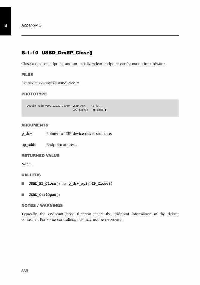
336
Appendix BB
B-1-10 USBD_DrvEP_Close()
Close a device endpoint, and un-initialize/clear endpoint configuration in hardware.
FILES
Every device driver’s usbd_drv.c
PROTOTYPE
ARGUMENTS
p_drv Pointer to USB device driver structure.
ep_addr Endpoint address.
RETURNED VALUE
None.
CALLERS
■ USBD_EP_Close() via 'p_drv_api->EP_Close()'
■ USBD_CtrlOpen()
NOTES / WARNINGS
Typically, the endpoint close function clears the endpoint information in the device
controller. For some controllers, this may not be necessary.
static void USBD_DrvEP_Close (USBD_DRV *p_drv,
CPU_INT08U ep_addr);
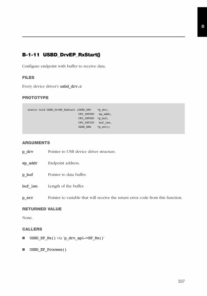
337
B
B-1-11 USBD_DrvEP_RxStart()
Configure endpoint with buffer to receive data.
FILES
Every device driver’s usbd_drv.c
PROTOTYPE
ARGUMENTS
p_drv Pointer to USB device driver structure.
ep_addr Endpoint address.
p_buf Pointer to data buffer.
buf_len Length of the buffer.
p_err Pointer to variable that will receive the return error code from this function.
RETURNED VALUE
None.
CALLERS
■ USBD_EP_Rx() via 'p_drv_api->EP_Rx()'
■ USBD_EP_Process()
static void USBD_DrvEP_RxStart (USBD_DRV *p_drv,
CPU_INT08U ep_addr,
CPU_INT08U *p_buf,
CPU_INT32U buf_len,
USBD_ERR *p_err);

338
Appendix BB
NOTES / WARNINGS
Typically, the function to configure the endpoint receive transaction performs the following
operations:
■ Determine maximum transaction length, given the specified length of the buffer
(buf_len).
■ Setup receive transaction.
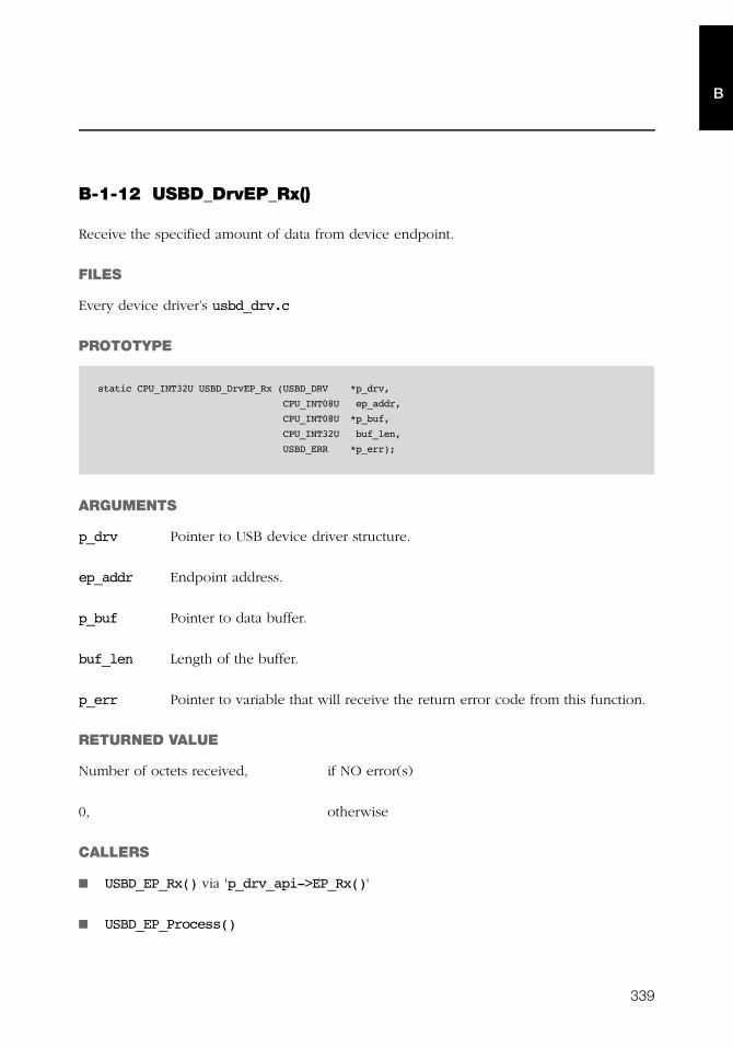
339
B
B-1-12 USBD_DrvEP_Rx()
Receive the specified amount of data from device endpoint.
FILES
Every device driver’s usbd_drv.c
PROTOTYPE
ARGUMENTS
p_drv Pointer to USB device driver structure.
ep_addr Endpoint address.
p_buf Pointer to data buffer.
buf_len Length of the buffer.
p_err Pointer to variable that will receive the return error code from this function.
RETURNED VALUE
Number of octets received, if NO error(s)
0, otherwise
CALLERS
■ USBD_EP_Rx() via 'p_drv_api->EP_Rx()'
■ USBD_EP_Process()
static CPU_INT32U USBD_DrvEP_Rx (USBD_DRV *p_drv,
CPU_INT08U ep_addr,
CPU_INT08U *p_buf,
CPU_INT32U buf_len,
USBD_ERR *p_err);
340
Appendix BB
NOTES / WARNINGS
Typically, the receive from endpoint function performs the following operations:
■ Check if packet has been received and is ready to be read.
■ Determine packet length.
■ If packet length is greater than buf_len, then copy the first buf_len octets into
p_buf. Otherwise, copy the entire packet into p_buf.
■ Clear endpoint buffer to allow next packet to be received. For some controllers, this
may not be necessary.
341
B
B-1-13 USBD_DrvEP_RxZLP()
Receive zero-length packet from endpoint.
FILES
Every device driver’s usbd_drv.c
PROTOTYPE
ARGUMENTS
p_drv Pointer to USB device driver structure.
ep_addr Endpoint address.
p_err Pointer to variable that will receive the return error code from this function.
RETURNED VALUE
None.
CALLERS
USBD_EP_RxZLP() via 'p_drv_api->EP_RxZLP()'
NOTES / WARNINGS
None.
static void USBD_DrvEP_RxZLP (USBD_DRV *p_drv,
CPU_INT08U ep_addr,
USBD_ERR *p_err);
342
Appendix BB
B-1-14 USBD_DrvEP_Tx()
Configure endpoint with buffer to transmit data.
FILES
Every device driver’s usbd_drv.c
PROTOTYPE
ARGUMENTS
p_drv Pointer to USB device driver structure.
ep_addr Endpoint address.
p_buf Pointer to data buffer.
buf_len Length of the buffer.
p_err Pointer to variable that will receive the return error code from this function.
RETURNED VALUE
Number of octets transmitted, if NO error(s).
0, otherwise.
CALLERS
■ USBD_EP_Tx() via 'p_drv_api->EP_Tx()'
■ USBD_EP_Process()
static CPU_INT32U USBD_DrvEP_Tx (USBD_DRV *p_drv,
CPU_INT08U ep_addr,
CPU_INT08U *p_buf,
CPU_INT32U buf_len,
USBD_ERR *p_err);
343
B
NOTES / WARNINGS
Typically, the function to configure the endpoint receive transaction performs the following
operations:
■ Check if data can be transmitted.
■ Write data to device endpoint.
■ Configure the packet length in USB device controller. This is often necessary when the
packet is shorter than the maximum packet size. Depending on the USB controller, this
operation may need to be performed prior to writing the data to the device endpoint.
344
Appendix BB
B-1-15 USBD_DrvEP_TxStart()
Transmit the specified amount of data to device endpoint.
FILES
Every device driver’s usbd_drv.c
PROTOTYPE
ARGUMENTS
p_drv Pointer to USB device driver structure.
ep_addr Endpoint address.
p_buf Pointer to data buffer.
buf_len Length of the buffer.
p_err Pointer to variable that will receive the return error code from this function.
RETURNED VALUE
Number of octets transmitted, if NO error(s).
0, otherwise.
static void USBD_DrvEP_TxStart (USBD_DRV *p_drv,
CPU_INT08U ep_addr,
CPU_INT08U *p_buf,
CPU_INT32U buf_len,
USBD_ERR *p_err);
345
B
CALLERS
■ USBD_EP_Tx() via 'p_drv_api->EP_TxStart()'
■ USBD_EP_Process()
NOTES / WARNINGS
Typically, the function to configure the endpoint receive transaction performs the following
operations:
■ Trigger packet transmission.
346
Appendix BB
B-1-16 USBD_DrvEP_TxZLP()
Transmit zero-length packet to endpoint.
FILES
Every device driver’s usbd_drv.c
PROTOTYPE
ARGUMENTS
p_drv Pointer to USB device driver structure.
ep_addr Endpoint address.
p_err Pointer to variable that will receive the return error code from this function.
RETURNED VALUE
None.
CALLERS
■ USBD_EP_Tx() via 'p_drv_api->EP_TxZLP()'
■ USBD_EP_TxZLP()
■ USBD_EP_Process()
NOTES / WARNINGS
None.
static void USBD_DrvEP_TxZLP (USBD_DRV *p_drv,
CPU_INT08U ep_addr,
USBD_ERR *p_err);
347
B
B-1-17 USBD_DrvEP_Abort()
Abort any pending transfer on endpoint.
FILES
Every device driver’s usbd_drv.c
PROTOTYPE
ARGUMENTS
p_drv Pointer to USB device driver structure.
ep_addr Endpoint Address.
RETURNED VALUE
DEF_OK, if NO error(s).
DEF_FAIL, otherwise.
CALLERS
USBD_URB_Abort() via 'p_drv_api->EP_Abort()'
NOTES / WARNINGS
None.
static CPU_BOOLEAN USBD_DrvEP_Abort (USBD_DRV *p_drv,
CPU_INT08U ep_addr);

348
Appendix BB
B-1-18 USBD_DrvEP_Stall()
Set or clear stall condition on endpoint.
FILES
Every device driver’s usbd_drv.c
PROTOTYPE
ARGUMENTS
p_drv Pointer to USB device driver structure.
ep_addr Endpoint address.
state Endpoint stall state.
RETURNED VALUE
DEF_OK, if NO error(s).
DEF_FAIL, otherwise.
CALLERS
■ USBD_EP_Stall() via 'p_drv_api->EP_Stall()'
■ USBD_CtrlStall()
NOTES / WARNINGS
None.
static CPU_BOOLEAN USBD_DrvEP_Stall (USBD_DRV *p_drv,
CPU_INT08U ep_addr,
CPU_BOOLEAN state);
349
B
B-1-19 USBD_DrvISR_Handler()
USB device Interrupt Service Routine (ISR) handler.
FILES
Every device driver’s usbd_drv.c
PROTOTYPE
ARGUMENTS
p_drv Pointer to USB device driver structure.
RETURNED VALUE
None.
CALLERS
Processor level kernel-aware interrupt handler.
NOTES / WARNINGS
None.
static void USBD_DrvISR_Handler (USBD_DRV *p_drv);
350
Appendix BB
B-2 DEVICE DRIVER BSP FUNCTIONS
B-2-1 USBD_BSP_Init()
Initialize board-specific USB controller dependencies.
FILES
Every device driver’s usbd_bsp.c
PROTOTYPE
ARGUMENTS
p_drv Pointer to USB device driver structure.
RETURNED VALUE
None.
CALLERS
USBD_DrvInit()
NOTES / WARNINGS
None.
static void USBD_BSP_Init (USBD_DRV *p_drv);
351
B
B-2-2 USBD_BSP_Conn()
Enable USB controller connection dependencies.
FILES
Every device driver’s usbd_bsp.c
PROTOTYPE
ARGUMENTS
None.
RETURNED VALUE
None.
CALLERS
USBD_DrvStart()
NOTES / WARNINGS
None.
static void USBD_BSP_Conn (void);
352
Appendix BB
B-2-3 USBD_BSP_Disconn()
Disable USB controller connection dependencies.
FILES
Every device driver’s usbd_bsp.c
PROTOTYPE
ARGUMENTS
None.
RETURNED VALUE
None.
CALLERS
USBD_DrvStop()
NOTES / WARNINGS
None.
static void USBD_BSP_Disconn (void);

353
Appendix
CCDC API Reference
This appendix provides a reference to the μC/USB-Device Communications Device Class
(CDC) API and Abstract Control Model (ACM) subclass API. The following information is
provided for each of the services:
■ A brief description
■ The function prototype
■ The filename of the source code
■ A description of the arguments passed to the function
■ A description of returned value(s)
■ Specific notes and warnings regarding use of the service
354
Appendix C
C
C-1 CDC FUNCTIONS
C-1-1 USBD_CDC_Init()
This function initializes all the internal variables and modules used by the CDC. The
initialization function is called by the application exactly once.
FILES
usbd_cdc.h/usbd_cdc.c
PROTOTYPE
ARGUMENTS
p_err Pointer to variable that will receive the return error code from this function:
USBD_ERR_NONE
RETURNED VALUE
None.
CALLERS
Application.
NOTES / WARNINGS
None.
static void USBD_CDC_Init (USBD_ERR *p_err);
355
C
C-1-2 USBD_CDC_Add()
This function creates a CDC instance.
FILES
usbd_cdc.h/usbd_cdc.c
PROTOTYPE
ARGUMENTS
subclass CDC subclass code.
USBD_CDC_SUBCLASS_RSVD Reserved value
USBD_CDC_SUBCLASS_DLCM Direct Line Control Model
USBD_CDC_SUBCLASS_ACM Abstract Control Model
USBD_CDC_SUBCLASS_TCM Telephone Control Model
USBD_CDC_SUBCLASS_MCC Multi-Channel Control Model
USBD_CDC_SUBCLASS_CAPICM CAPI Control Model
USBD_CDC_SUBCLASS_WHCM Wireless Handset Control Model
USBD_CDC_SUBCLASS_DEV_MGMT Device Management
USBD_CDC_SUBCLASS_MDLM Device Management
USBD_CDC_SUBCLASS_OBEX Obex
USBD_CDC_SUBCLASS_EEM Ethernet Emulation Model
USBD_CDC_SUBCLASS_NCM Network Control Model
USBD_CDC_SUBCLASS_VENDOR Vendor specific
CDC subclass codes are defined in the Universal Serial Bus Class Definitions
for Communication Devices Revision 2.1 Table 4.
CPU_INT08U USBD_CDC_Add(CPU_INT08U subclass,
USBD_CDC_SUBCLASS_DRV *p_subclass_drv,
void *p_subclass_arg,
CPU_INT08U protocol,
CPU_BOOLEAN notify_en,
CPU_INT16U notify_interval,
USBD_ERR *p_err);
356
Appendix C
C
p_subclass_drv Pointer to CDC subclass driver.
p_subclass_arg Pointer to CDC subclass driver argument.
protocol CDC protocol code.
USBD_CDC_COMM_PROTOCOL_NONE
USBD_CDC_COMM_PROTOCOL_AT_V250
USBD_CDC_COMM_PROTOCOL_AT_PCCA_101
USBD_CDC_COMM_PROTOCOL_AT_PCCA_101_ANNEX
USBD_CDC_COMM_PROTOCOL_AT_GSM_7_07
USBD_CDC_COMM_PROTOCOL_AT_3GPP_27_07
USBD_CDC_COMM_PROTOCOL_AT_TIA_CDMA
USBD_CDC_COMM_PROTOCOL_EEM
USBD_CDC_COMM_PROTOCOL_EXT
USBD_CDC_COMM_PROTOCOL_VENDOR
CDC protocol codes are defined in the Universal Serial Bus Class Definitions
for Communication Devices Revision 2.1 Table 5.
notify_en Notification enabled.
DEF_ENABLED CDC notifications are enabled.
DEF_DISABLED CDC notifications are disabled.
notify_interval Notification interval in milliseconds.
p_err Pointer to variable that will receive the return error code from this function.
USBD_ERR_NONE
USBD_ERR_ALLOC
RETURNED VALUE
CDC class interface number, if CDC class successfully created.
USBD_CDC_NBR_NONE, otherwise.
357
C
CALLERS
CDC Subclass drivers.
NOTES / WARNINGS
The CDC defines a communication class interface consisting of a management element and
optionally a notification element. The notification element transports event to the host. The
enable_en enable notifications in the CDC. The notification are sent to the host using an
interrupt endpoint, the interval of the interrupt endpoint is specified by the
notify_interval parameter.
358
Appendix C
C
C-1-3 USBD_CDC_CfgAdd()
Add a CDC instance to specific USB configuration.
FILES
usbd_cdc.h/usbd_cdc.c
PROTOTYPE
ARGUMENTS
class_nbr CDC instance number.
dev_nbr Device number.
cfg_nbr Configuration number.
p_err Pointer to variable that will receive the return error code from this function.
USBD_ERR_NONE
USBD_ERR_ALLOC
USBD_ERR_INVALID_ARG
USBD_ERR_DEV_INVALID_NBR
USBD_ERR_DEV_INVALID_STATE
USBD_ERR_CFG_INVALID_NBR
USBD_ERR_IF_ALLOC
USBD_ERR_IF_ALT_ALLOC
USBD_ERR_IF_INVALID_NBR
USBD_ERR_IF_GRP_NBR_IN_USE
USBD_ERR_IF_GRP_ALLOC
USBD_ERR_EP_NONE_AVAIL
USBD_ERR_EP_ALLOC
CPU_BOOLEAN USBD_CDC_CfgAdd (CPU_INT08U class_nbr,
CPU_INT08U dev_nbr,
CPU_INT08U cfg_nbr,
USBD_ERR *p_err);
359
C
RETURNED VALUE
DEF_OK, if CDC class instance was added to device configuration successfully.
DEF_FAIL, otherwise.
CALLERS
CDC Subclass drivers.
NOTES / WARNINGS
None.
360
Appendix C
C
C-1-4 USBD_CDC_IsConn()
Determine if CDC instance is connected.
FILES
usbd_cdc.h/usbd_cdc.c
PROTOTYPE
ARGUMENTS
class_nbr CDC instance number.
RETURNED VALUE
DEF_OK, if CDC instance is connected and device is not in suspended state.
DEF_FAIL, otherwise.
CALLERS
■ CDC Subclass drivers
■ Application
NOTES / WARNINGS
If the USBD_CDC_IsConn() returns DEF_OK, than the CDC instance is ready for management,
notification, read and write operations.
CPU_BOOLEAN USBD_CDC_IsConn (CPU_INT08U class_nbr)
361
C
C-1-5 USBD_CDC_DataIF_Add()
Add a data interface class to CDC.
FILES
usbd_cdc.h/usbd_cdc.c
PROTOTYPE
ARGUMENTS
class_nbr CDC instance number.
isoc_en Data interface isochronous enable.
DEF_ENABLED Data interface uses isochronous
endpoints.
DEF_DISABLED Data interface uses bulk endpoints.
protocol Data interface protocol code:
USBD_CDC_DATA_PROTOCOL_NONE No class specific protocol required.
USBD_CDC_DATA_PROTOCOL_NTB Network Transfer Block.
USBD_CDC_DATA_PROTOCOL_PHY Physical interface protocol for ISDN BRI.
USBD_CDC_DATA_PROTOCOL_HDLC HDLC.
USBD_CDC_DATA_PROTOCOL_TRANS Transparent.
USBD_CDC_DATA_PROTOCOL_Q921M Management protocol for Q.921 data link
protocol.
USBD_CDC_DATA_PROTOCOL_Q921 Data link protocol for Q.921.
USBD_CDC_DATA_PROTOCOL_Q921TM TEI-multiplexor for Q.921 data link
protocol
USBD_CDC_DATA_PROTOCOL_COMPRESS Data compression procedures.
USBD_CDC_DATA_PROTOCOL_Q9131 Euro-ISDN protocol control.
CPU_INT08U USBD_CDC_DataIF_Add (CPU_INT08U class_nbr,
CPU_BOOLEAN isoc_en,
CPU_INT08U protocol,
USBD_ERR *p_err);
362
Appendix C
C
USBD_CDC_DATA_PROTOCOL_V24 V.24 rate adaptation to ISDN.
USBD_CDC_DATA_PROTOCOL_CAPI CAPI Commands.
USBD_CDC_DATA_PROTOCOL_HOST Host based driver.
USBD_CDC_DATA_PROTOCOL_CDC The protocol(s) are described using a
Protocol Unit Function Communication
Class Interface.
USBD_CDC_DATA_PROTOCOL_VENDOR Vendor-specific.
CDC data interface class protocol codes are defined in the Universal Serial
Bus Class Definitions for Communication Devices Revision 2.1 Table 7.
p_err Pointer to variable that will receive the return error code from this function.
USBD_ERR_NONE
USBD_ERR_ALLOC
USBD_ERR_INVALID_ARG
RETURNED VALUE
Data interface number, if no errors.
USBD_CDC_DATA_IF_NBR_NONE, otherwise.
CALLERS
CDC Subclass drivers.
NOTES / WARNINGS
None.
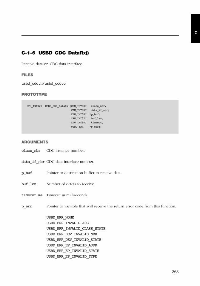
363
C
C-1-6 USBD_CDC_DataRx()
Receive data on CDC data interface.
FILES
usbd_cdc.h/usbd_cdc.c
PROTOTYPE
ARGUMENTS
class_nbr CDC instance number.
data_if_nbr CDC data interface number.
p_buf Pointer to destination buffer to receive data.
buf_len Number of octets to receive.
timeout_ms Timeout in milliseconds.
p_err Pointer to variable that will receive the return error code from this function.
USBD_ERR_NONE
USBD_ERR_INVALID_ARG
USBD_ERR_INVALID_CLASS_STATE
USBD_ERR_DEV_INVALID_NBR
USBD_ERR_DEV_INVALID_STATE
USBD_ERR_EP_INVALID_ADDR
USBD_ERR_EP_INVALID_STATE
USBD_ERR_EP_INVALID_TYPE
CPU_INT32U USBD_CDC_DataRx (CPU_INT08U class_nbr,
CPU_INT08U data_if_nbr,
CPU_INT08U *p_buf,
CPU_INT32U buf_len,
CPU_INT16U timeout,
USBD_ERR *p_err);

364
Appendix C
C
USBD_ERR_OS_TIMEOUT
USBD_ERR_OS_ABORT
USBD_ERR_OS_FAIL
RETURNED VALUE
Numbers of octets received, if no errors.
0, otherwise.
CALLERS
CDC Subclass drivers.
NOTES / WARNINGS
None.

365
C
C-1-7 USBD_CDC_DataTx()
Send data on CDC data class interface.
FILES
usbd_cdc.h/usbd_cdc.c
PROTOTYPE
ARGUMENTS
class_nbr CDC instance number.
data_if_nbr CDC data interface number.
p_buf Pointer to buffer of data that will be transmitted.
buf_len Number of octets to transmit.
timeout_ms Timeout in milliseconds.
p_err Pointer to variable that will receive the return error code from this function.
USBD_ERR_NONE
USBD_ERR_INVALID_ARG
USBD_ERR_INVALID_CLASS_STATE
USBD_ERR_DEV_INVALID_NBR
USBD_ERR_DEV_INVALID_STATE
USBD_ERR_EP_INVALID_ADDR
USBD_ERR_EP_INVALID_STATE
USBD_ERR_EP_INVALID_TYPE
CPU_INT32U USBD_CDC_DataTx (CPU_INT08U class_nbr,
CPU_INT08U data_if_nbr,
CPU_INT08U *p_buf,
CPU_INT32U buf_len,
CPU_INT16U timeout,
USBD_ERR *p_err);

366
Appendix C
C
USBD_ERR_OS_TIMEOUT
USBD_ERR_OS_ABORT
USBD_ERR_OS_FAIL
RETURNED VALUE
Numbers of octets transmitted, if no errors.
0, otherwise.
CALLERS
CDC Subclass drivers.
NOTES / WARNINGS
None.
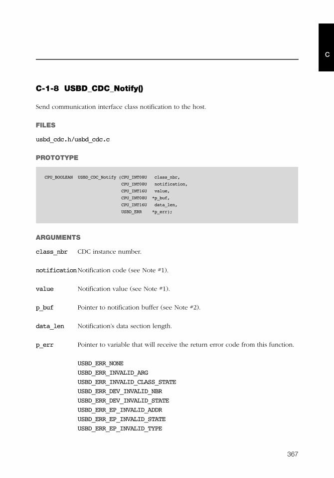
367
C
C-1-8 USBD_CDC_Notify()
Send communication interface class notification to the host.
FILES
usbd_cdc.h/usbd_cdc.c
PROTOTYPE
ARGUMENTS
class_nbr CDC instance number.
notificationNotification code (see Note #1).
value Notification value (see Note #1).
p_buf Pointer to notification buffer (see Note #2).
data_len Notification’s data section length.
p_err Pointer to variable that will receive the return error code from this function.
USBD_ERR_NONE
USBD_ERR_INVALID_ARG
USBD_ERR_INVALID_CLASS_STATE
USBD_ERR_DEV_INVALID_NBR
USBD_ERR_DEV_INVALID_STATE
USBD_ERR_EP_INVALID_ADDR
USBD_ERR_EP_INVALID_STATE
USBD_ERR_EP_INVALID_TYPE
CPU_BOOLEAN USBD_CDC_Notify (CPU_INT08U class_nbr,
CPU_INT08U notification,
CPU_INT16U value,
CPU_INT08U *p_buf,
CPU_INT16U data_len,
USBD_ERR *p_err);
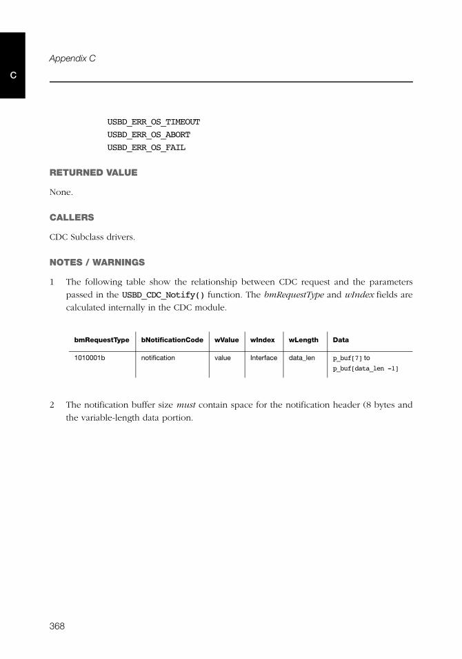
368
Appendix C
C
USBD_ERR_OS_TIMEOUT
USBD_ERR_OS_ABORT
USBD_ERR_OS_FAIL
RETURNED VALUE
None.
CALLERS
CDC Subclass drivers.
NOTES / WARNINGS
1 The following table show the relationship between CDC request and the parameters
passed in the USBD_CDC_Notify() function. The bmRequestType and wIndex fields are
calculated internally in the CDC module.
2 The notification buffer size must contain space for the notification header (8 bytes and
the variable-length data portion.
bmRequestType bNotificationCode wValue wIndex wLength Data
1010001b notification value Interface data_len p_buf[7] to
p_buf[data_len -1]
369
C
C-2 CDC ACM SUBCLASS FUNCTIONS
C-2-1 USBD_ACM_SerialInit()
Initialize CDC ACM serial emulation subclass.
FILES
usbd_acm_serial.h/usbd_acm_serial.c
PROTOTYPE
ARGUMENTS
p_err Pointer to variable that will receive the return error code from this function:
USBD_ERR_NONE.
RETURNED VALUE
None.
CALLERS
Application.
NOTES / WARNINGS
None.
void USBD_ACM_SerialInit (USBD_ERR *p_err);
370
Appendix C
C
C-2-2 USBD_ACM_SerialAdd()
Add a new CDC ACM serial emulation instance.
FILES
usbd_acm_serial.h/usbd_acm_serial.c
PROTOTYPE
ARGUMENTS
line_state_interval Polling interval in frames or microframes for line state
notification.
p_err Pointer to variable that will receive the return error code from this function.
USBD_ERR_NONE
USBD_ERR_ALLOC
USBD_ERR_INVALID_ARG
RETURNED VALUE
CDC ACM serial emulation subclass instance number,if no errors.
USBD_ACM_SERIAL_NBR_NONE, otherwise.
CALLERS
Application.
NOTES / WARNINGS
None.
CPU_INT08U USBD_ACM_SerialAdd (CPU_INT16U line_state_interval,
USBD_ERR *p_err);
371
C
C-2-3 USBD_ACM_SerialCfgAdd()
Add CDC ACM subclass instance to USB device configuration.
FILES
usbd_acm_serial.h/usbd_acm_serial.c
PROTOTYPE
ARGUMENTS
subclass_nbr CDC ACM serial emulation subclass instance number.
dev_nbr Device number.
cfg_nbr Configuration number.
p_err Pointer to variable that will receive the return error code from this function.
USBD_ERR_NONE
USBD_ERR_INVALID_ARG
USBD_ERR_ALLOC
USBD_ERR_INVALID_CLASS_STATE
USBD_ERR_DEV_INVALID_NBR
USBD_ERR_CFG_INVALID_NBR
USBD_ERR_IF_ALLOC
USBD_ERR_IF_ALT_ALLOC
USBD_ERR_EP_NONE_AVAIL
USBD_ERR_EP_ALLOC
CPU_BOOLEAN USBD_ACM_SerialCfgAdd (CPU_INT08U subclass_nbr,
CPU_INT08U dev_nbr,
CPU_INT08U cfg_nbr,
USBD_ERR *p_err);
372
Appendix C
C
RETURNED VALUE
DEF_OK, If CDC ACM serial emulation subclass instance was added to device
configuration successfully.
DEF_FAIL, Otherwise.
CALLERS
Application.
NOTES / WARNINGS
None.
373
C
C-2-4 USBD_ACM_SerialIsConn()
Determine if CDC ACM serial emulation class instance is connected.
FILES
usbd_acm_serial.h/usbd_acm_serial.c
PROTOTYPE
ARGUMENTS
subclass_nbr CDC ACM serial emulation subclass instance number.
RETURNED VALUE
DEF_OK, If CDC ACM serial emulation subclass instance is connected and device is not
in suspended state.
DEF_FAIL, otherwise.
CALLERS
Application.
NOTES / WARNINGS
None.
CPU_BOOLEAN USBD_ACM_SerialIsConn (CPU_INT08U subclass_nbr);

374
Appendix C
C
C-2-5 USBD_ACM_SerialRx()
Receive data on CDC ACM serial emulation subclass.
FILES
usbd_acm_serial.h/usbd_acm_serial.c
PROTOTYPE
ARGUMENTS
subclass_nbr Pointer to USB device driver structure.
p_buf Pointer to destination buffer to receive data.
buf_len Number of octets to receive.
timeout_ms Timeout in milliseconds.
p_err Pointer to variable that will receive the return error code from this function.
USBD_ERR_NONE
USBD_ERR_INVALID_ARG
USBD_ERR_INVALID_CLASS_STATE
USBD_ERR_EP_INVALID_ADDR
USBD_ERR_EP_INVALID_STATE
USBD_ERR_EP_INVALID_TYPE
USBD_ERR_OS_TIMEOUT
USBD_ERR_OS_ABORT
USBD_ERR_OS_FAIL
CPU_INT32U USBD_ACM_SerialRx (CPU_INT08U subclass_nbr,
CPU_INT08U *p_buf,
CPU_INT32U buf_len,
CPU_INT16U timeout,
USBD_ERR *p_err);

375
C
RETURNED VALUE
None.
CALLERS
Numbers of octets received, if NO error(s).
0, otherwise.
NOTES / WARNINGS
None.

376
Appendix C
C
C-2-6 USBD_ACM_SerialTx()
Send data on CDC ACM serial emulation subclass.
FILES
usbd_acm_serial.h/usbd_acm_serial.c
PROTOTYPE
ARGUMENTS
subclass_nbr Pointer to USB device driver structure.
p_buf Pointer to buffer of data that will be transmitted.
buf_len Number of octets to receive.
timeout_ms Timeout in milliseconds.
p_err Pointer to variable that will receive the return error code from this function.
USBD_ERR_NONE
USBD_ERR_INVALID_ARG
USBD_ERR_INVALID_CLASS_STATE
USBD_ERR_EP_INVALID_ADDR
USBD_ERR_EP_INVALID_STATE
USBD_ERR_EP_INVALID_TYPE
USBD_ERR_OS_TIMEOUT
USBD_ERR_OS_ABORT
USBD_ERR_OS_FAIL
CPU_INT32U USBD_ACM_SerialTx (CPU_INT08U subclass_nbr,
CPU_INT08U *p_buf,
CPU_INT32U buf_len,
CPU_INT16U timeout,
USBD_ERR *p_err);

377
C
RETURNED VALUE
Number of octets transmitted, if NO error(s).
0, otherwise.
CALLERS
Application.
NOTES / WARNINGS
None.
378
Appendix C
C
C-2-7 USBD_ACM_SerialLineCtrlGet()
Return current control line state.
FILES
usbd_acm_serial.h/usbd_acm_serial.c
PROTOTYPE
ARGUMENTS
subclass_nbr CDC ACM serial emulation subclass instance number.
p_err Pointer to variable that will receive the return error code from this function.
USBD_ERR_NONE
USBD_ERR_INVALID_ARG
RETURNED VALUE
Bit-field with the state of the control line.
USBD_ACM_SERIAL_CTRL_BREAK Break signal is set.
USBD_ACM_SERIAL_CTRL_RTS RTS signal is set.
USBD_ACM_SERIAL_CTRL_DTR DTR signal is set.
CALLERS
Application.
NOTES / WARNINGS
None.
CPU_INT08U USBD_ACM_SerialLineCtrlGet (CPU_INT08U subclass_nbr,
USBD_ERR *p_err);
379
C
C-2-8 USBD_ACM_SerialLineCtrlReg()
Register line control change notification callback.
FILES
usbd_acm_serial.h/usbd_acm_serial.c
PROTOTYPE
ARGUMENTS
subclass_nbr CDC ACM serial emulation subclass instance number.
line_ctrl_chngd Line control change notification callback (see note #1).
p_arg Pointer to callback argument.
p_err Pointer to variable that will receive the return error code from this function.
USBD_ERR_NONE
USBD_ERR_INVALID_ARG
RETURNED VALUE
None.
CALLERS
Application.
void USBD_ACM_SerialLineCtrlReg (CPU_INT08U subclass_nbr,
USBD_ACM_SERIAL_LINE_CTRL_CHNGD line_ctrl_chngd,
void *p_arg,
USBD_ERR *p_err);
380
Appendix C
C
NOTES / WARNINGS
The callback specified by line_ctrl_chngd argument is used to notify changes in the
control signals to the application.
The line control notification function has the following prototype:
Argument(s):
subclass_nbr CDC ACM serial emulation subclass instance number.
events Current line state.
events_chngd Line state flags that have changed.
events_chngd Pointer to callback argument.
void AppLineCtrlChngd (CPU_INT08U subclass_nbr,
CPU_INT08U events,
CPU_INT08U events_chngd,
void *p_arg);
381
C
C-2-9 USBD_ACM_SerialLineCodingGet()
Get the current state of the line coding.
FILES
usbd_acm_serial.h/usbd_acm_serial.c
PROTOTYPE
ARGUMENTS
subclass_nbr CDC ACM serial emulation subclass instance number.
p_line_coding Pointer to the structure where the current line coding will be
stored.
p_err Pointer to variable that will receive the return error code from this function.
USBD_ERR_NONE
USBD_ERR_INVALID_ARG
USBD_ERR_NULL_PTR
RETURNED VALUE
None.
CALLERS
Application.
NOTES / WARNINGS
None.
void USBD_ACM_SerialLineCodingGet (CPU_INT08U subclass_nbr,
USBD_ACM_SERIAL_LINE_CODING *p_line_coding,
USBD_ERR *p_err);
382
Appendix C
C
C-2-10 USBD_ACM_SerialLineCodingSet()
Set a new line coding.
FILES
usbd_acm_serial.h/usbd_acm_serial.c
PROTOTYPE
ARGUMENTS
subclass_nbr CDC ACM serial emulation subclass instance number.
p_line_coding Pointer to the structure where that contains the new line coding.
p_err Pointer to variable that will receive the return error code from this function.
USBD_ERR_NONE
USBD_ERR_INVALID_ARG
USBD_ERR_NULL_PTR
RETURNED VALUE
None.
CALLERS
Application.
NOTES / WARNINGS
None.
void USBD_ACM_SerialLineCodingSet (CPU_INT08U subclass_nbr,
USBD_ACM_SERIAL_LINE_CODING *p_line_coding,
USBD_ERR *p_err);
383
C
C-2-11 USBD_ACM_SerialLineCodingReg()
Register line coding change notification callback.
FILES
usbd_acm_serial.h/usbd_acm_serial.c
PROTOTYPE
ARGUMENTS
subclass_nbr CDC ACM serial emulation subclass instance number.
line_coding_chngd Line coding change notification callback (see Note #1).
p_arg Pointer to callback argument.
p_err Pointer to variable that will receive the return error code from this function.
USBD_ERR_NONE
USBD_ERR_INVALID_ARG
RETURNED VALUE
None.
CALLERS
Application.
void USBD_ACM_SerialLineCodingReg(CPU_INT08U subclass_nbr,
USBD_ACM_SERIAL_LINE_CODING_CHNGD line_coding_chngd,
void *p_arg,
USBD_ERR *p_err);

384
Appendix C
C
NOTES / WARNINGS
■ The callback specified by line_coding_chngd argument is used to notify changes in
the control signals to the application.
The line control notification function has the following prototype:
Arguments:
subclass_nbr CDC ACM serial emulation subclass instance number.
p_line_coding Pointer to line coding structure.
p_arg Pointer to callback argument.
Returned value:
DEF_OK, If line coding is supported by the application.
DEF_FAIL, Otherwise.
CPU_BOOLEAN AppLineCodingChngd (CPU_INT08U subclass_nbr,
... *p_line_coding,
void *p_arg);
385
C
C-2-12 USBD_ACM_SerialLineStateSet()
Set one or several line state events.
FILES
usbd_acm_serial.h/usbd_acm_serial.c
PROTOTYPE
ARGUMENTS
subclass_nbr CDC ACM serial emulation subclass instance number.
events Line state event(s) to set.
USBD_ACM_SERIAL_STATE_DCD DCD (Rx carrier)
USBD_ACM_SERIAL_STATE_DSR DSR (Tx carrier)
USBD_ACM_SERIAL_STATE_BREAK Break
USBD_ACM_SERIAL_STATE_RING Ring
USBD_ACM_SERIAL_STATE_FRAMINGFraming error
USBD_ACM_SERIAL_STATE_PARITY Parity error
USBD_ACM_SERIAL_STATE_OVERUN Overrun
RETURNED VALUE
DEF_OK, if new line state event set successfully.
DEF_FAIL, otherwise.
CALLERS
Application.
NOTES / WARNINGS
None.
CPU_BOOLEAN USBD_ACM_SerialLineStateSet (CPU_INT08U subclass_nbr,
CPU_INT08U events);
386
Appendix C
C
C-2-13 USBD_ACM_SerialLineStateClr()
Clear one or several line state event(s).
FILES
usbd_acm_serial.h/usbd_acm_serial.c
PROTOTYPE
ARGUMENTS
subclass_nbr CDC ACM serial emulation subclass instance number.
events Line state event(s) to clear (see Note #1).
USBD_ACM_SERIAL_STATE_DCD DCD (Rx carrier)
USBD_ACM_SERIAL_STATE_DSR DSR (Tx carrier)
RETURNED VALUE
DEF_OK, if new line state event clear successfully.
DEF_FAIL, otherwise.
CALLERS
Application.
NOTES / WARNINGS
■ Universal Serial Bus Communications Class Subclass Specification for PSTN Devices
version 1.2 states: “For the irregular signals like break, the incoming ring signal, or the
overrun error state, this will reset their values to zero and again will not send another
notification until their state changes”. The irregular events are self-clear and cannot be
clear using this function.
CPU_BOOLEAN USBD_ACM_SerialLineStateSet (CPU_INT08U subclass_nbr,
CPU_INT08U events);
387
Appendix
DHID API Reference
This appendix provides a reference to the Human Interface Device (HID) class API. The
following information is provided for each of the services:
■ A brief description
■ The function prototype
■ The filename of the source code
■ A description of the arguments passed to the function
■ A description of returned value(s)
■ Specific notes and warnings regarding use of the service
388
Appendix D
D
D-1 HID CLASS FUNCTIONS
D-1-1 USBD_HID_Init()
This function initializes all the internal variables and modules used by the HID class.
FILES
usbd_hid.c
PROTOTYPE
ARGUMENTS
p_err Pointer to variable that will receive the return error code from this function.
USBD_ERR_NONE
RETURNED VALUE
None.
CALLERS
Application.
NOTES / WARNINGS
The initialization function must be called only once by the application, and before calling
any other HID API.
void USBD_HID_Init (USBD_ERR *p_err);
389
D
D-1-2 USBD_HID_Add()
This function adds a new instance of the HID class.
FILES
usbd_hid.c
PROTOTYPE
ARGUMENTS
subclass Subclass code.
protocol Protocol code.
country_code Country code ID.
p_report_desc Pointer to report descriptor structure.
report_desc_len Report descriptor length.
p_phy_desc Pointer to physical descriptor structure.
phy_desc_len Physical descriptor length.
interval_in Polling interval for input transfers, in milliseconds.
void USBD_HID_Add (CPU_INT08U subclass,
CPU_INT08U protocol,
USBD_HID_COUNTRY_CODE country_code,
CPU_INT08U *p_report_desc,
CPU_INT16U report_desc_len,
CPU_INT08U *p_phy_desc,
CPU_INT16U phy_desc_len,
CPU_INT16U interval_in,
CPU_INT16U interval_out,
CPU_BOOLEAN ctrl_rd_en,
USBD_HID_CALLBACK *p_hid_callback,
USBD_ERR *p_err);
390
Appendix D
D
interval_out Polling interval for output transfers, in milliseconds. Used only
when read operations are not through control transfers.
ctrl_rd_en Enable read operations through control transfers.
p_hid_callback Pointer to HID descriptor and request callback structure.
p_err Pointer to variable that will receive the return error code from this function.
USBD_ERR_NONE
USBD_ERR_ALLOC
USBD_ERR_NULL_PTR
USBD_ERR_INVALID_ARG
USBD_ERR_FAIL
RETURNED VALUE
Class interface number, if NO error(s).
USBD_CLASS_NBR_NONE, otherwise.
CALLERS
Application.
NOTES / WARNINGS
None.
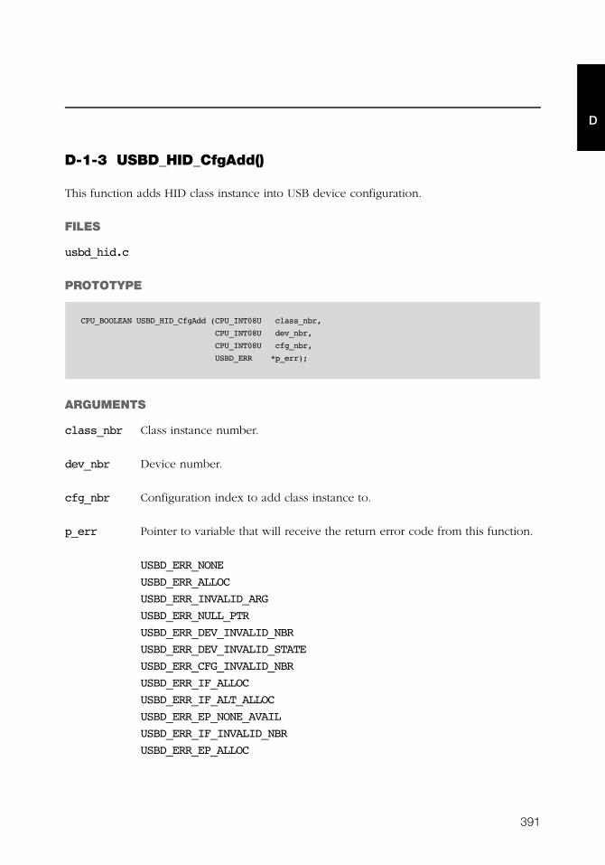
391
D
D-1-3 USBD_HID_CfgAdd()
This function adds HID class instance into USB device configuration.
FILES
usbd_hid.c
PROTOTYPE
ARGUMENTS
class_nbr Class instance number.
dev_nbr Device number.
cfg_nbr Configuration index to add class instance to.
p_err Pointer to variable that will receive the return error code from this function.
USBD_ERR_NONE
USBD_ERR_ALLOC
USBD_ERR_INVALID_ARG
USBD_ERR_NULL_PTR
USBD_ERR_DEV_INVALID_NBR
USBD_ERR_DEV_INVALID_STATE
USBD_ERR_CFG_INVALID_NBR
USBD_ERR_IF_ALLOC
USBD_ERR_IF_ALT_ALLOC
USBD_ERR_EP_NONE_AVAIL
USBD_ERR_IF_INVALID_NBR
USBD_ERR_EP_ALLOC
CPU_BOOLEAN USBD_HID_CfgAdd (CPU_INT08U class_nbr,
CPU_INT08U dev_nbr,
CPU_INT08U cfg_nbr,
USBD_ERR *p_err);
392
Appendix D
D
RETURNED VALUE
DEF_YES, if NO error(s).
DEF_NO, otherwise.
CALLERS
Application.
NOTES / WARNINGS
This API may be called several times. This allows to create multiple instances of the HID
class into different USB device configurations.
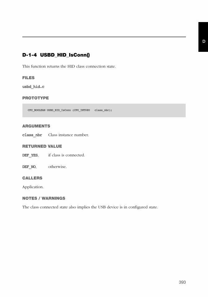
393
D
D-1-4 USBD_HID_IsConn()
This function returns the HID class connection state.
FILES
usbd_hid.c
PROTOTYPE
ARGUMENTS
class_nbr Class instance number.
RETURNED VALUE
DEF_YES, if class is connected.
DEF_NO, otherwise.
CALLERS
Application.
NOTES / WARNINGS
The class connected state also implies the USB device is in configured state.
CPU_BOOLEAN USBD_HID_IsConn (CPU_INT08U class_nbr);
394
Appendix D
D
D-1-5 USBD_HID_Rd()
This function receives data from the host through an interrupt OUT endpoint.
FILES
usbd_hid.c
PROTOTYPE
ARGUMENTS
class_nbr Class instance number.
p_buf Pointer to receive buffer.
buf_len Receive buffer length, in octets.
timeout Timeout, in milliseconds.
p_err Pointer to variable that will receive the return error code from this function.
USBD_ERR_NONE
USBD_ERR_NULL_PTR
USBD_ERR_INVALID_ARG
USBD_ERR_INVALID_CLASS_STATE
USBD_ERR_DEV_INVALID_NBR
USBD_ERR_EP_INVALID_NBR
USBD_ERR_DEV_INVALID_STATE
USBD_ERR_EP_INVALID_TYPE
CPU_INT32U USBD_HID_Rd (CPU_INT08U class_nbr,
void *p_buf,
CPU_INT32U buf_len,
CPU_INT16U timeout,
USBD_ERR *p_err);

395
D
RETURNED VALUE
Number of octets received, if NO error(s).
0, otherwise.
CALLERS
Application.
NOTES / WARNINGS
None.
396
Appendix D
D
D-1-6 USBD_HID_RdAsync()
This function receives data from the host asynchronously through an interrupt OUT
endpoint.
FILES
usbd_hid.c
PROTOTYPE
ARGUMENTS
class_nbr Class instance number.
p_buf Pointer to receive buffer.
buf_len Receive buffer length, in octets.
async_fnct Receive callback.
p_async_arg Additional argument provided by application for receive callback.
p_err Pointer to variable that will receive the return error code from this function.
USBD_ERR_NONE
USBD_ERR_NULL_PTR
USBD_ERR_INVALID_ARG
USBD_ERR_INVALID_CLASS_STATE
USBD_ERR_FAIL
USBD_ERR_DEV_INVALID_NBR
USBD_ERR_EP_INVALID_NBR
void USBD_HID_RdAsync (CPU_INT08U class_nbr,
void *p_buf,
CPU_INT32U buf_len,
USBD_HID_ASYNC_FNCT async_fnct,
void *p_async_arg,
USBD_ERR *p_err);

397
D
USBD_ERR_DEV_INVALID_STATE
USBD_ERR_EP_INVALID_TYPE
USBD_ERR_EP_INVALID_STATE
RETURNED VALUE
None.
CALLERS
Application.
NOTES / WARNINGS
This function is non-blocking and returns immediately after transfer preparation. Upon
transfer completion, the callback provided is called to notify the application.

398
Appendix D
D
D-1-7 USBD_HID_Wr()
This function transmits data to the host through an interrupt IN endpoint.
FILES
usbd_hid.c
PROTOTYPE
ARGUMENTS
class_nbr Class instance number.
p_buf Pointer to transmit buffer.
buf_len Transmit buffer length, in octets.
timeout Timeout, in milliseconds.
p_err Pointer to variable that will receive the return error code from this function.
USBD_ERR_NONE
USBD_ERR_NULL_PTR
USBD_ERR_INVALID_ARG
USBD_ERR_INVALID_CLASS_STATE
USBD_ERR_DEV_INVALID_NBR
USBD_ERR_EP_INVALID_NBR
USBD_ERR_DEV_INVALID_STATE
USBD_ERR_EP_INVALID_TYPE
CPU_INT32U USBD_HID_Wr (CPU_INT08U class_nbr,
void *p_buf,
CPU_INT32U buf_len,
CPU_INT16U timeout,
USBD_ERR *p_err);
399
D
RETURNED VALUE
Number of octets transmitted, if NO error(s).
0, otherwise.
CALLERS
Application.
NOTES / WARNINGS
None.
400
Appendix D
D
D-1-8 USBD_HID_WrAsync()
This function transmits data to the host asynchronously through an interrupt IN endpoint.
FILES
usbd_hid.c
PROTOTYPE
ARGUMENTS
class_nbr Class instance number.
p_buf Pointer to transmit buffer.
buf_len Transmit buffer length, in octets.
async_fnct Transmit callback.
p_async_arg Additional argument provided by application for transmit callback.
p_err Pointer to variable that will receive the return error code from this function.
USBD_ERR_NONE
USBD_ERR_NULL_PTR
USBD_ERR_INVALID_ARG
USBD_ERR_INVALID_CLASS_STATE
USBD_ERR_FAIL
USBD_ERR_DEV_INVALID_NBR
USBD_ERR_EP_INVALID_NBR
USBD_ERR_DEV_INVALID_STATE
USBD_ERR_EP_INVALID_TYPE
USBD_ERR_EP_INVALID_STATE
void USBD_HID_WrAsync (CPU_INT08U class_nbr,
void *p_buf,
CPU_INT32U buf_len,
USBD_HID_ASYNC_FNCT async_fnct,
void *p_async_arg,
USBD_ERR *p_err);
401
D
RETURNED VALUE
None.
CALLERS
Application.
NOTES / WARNINGS
This function is non-blocking and returns immediately after transfer preparation. Upon
transfer completion, the callback provided is called to notify the application.
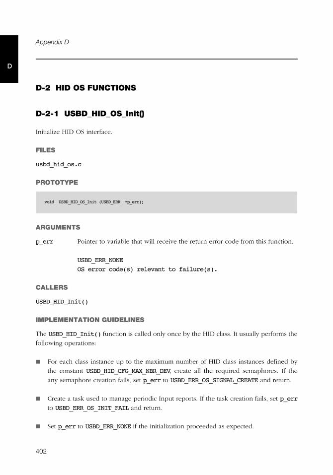
402
Appendix D
D
D-2 HID OS FUNCTIONS
D-2-1 USBD_HID_OS_Init()
Initialize HID OS interface.
FILES
usbd_hid_os.c
PROTOTYPE
ARGUMENTS
p_err Pointer to variable that will receive the return error code from this function.
USBD_ERR_NONE
OS error code(s) relevant to failure(s).
CALLERS
USBD_HID_Init()
IMPLEMENTATION GUIDELINES
The USBD_HID_Init() function is called only once by the HID class. It usually performs the
following operations:
■ For each class instance up to the maximum number of HID class instances defined by
the constant USBD_HID_CFG_MAX_NBR_DEV, create all the required semaphores. If the
any semaphore creation fails, set p_err to USBD_ERR_OS_SIGNAL_CREATE and return.
■ Create a task used to manage periodic Input reports. If the task creation fails, set p_err
to USBD_ERR_OS_INIT_FAIL and return.
■ Set p_err to USBD_ERR_NONE if the initialization proceeded as expected.
void USBD_HID_OS_Init (USBD_ERR *p_err);
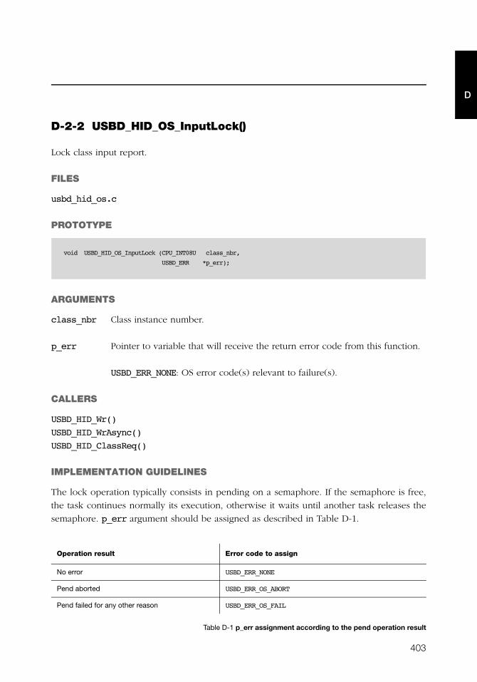
403
D
D-2-2 USBD_HID_OS_InputLock()
Lock class input report.
FILES
usbd_hid_os.c
PROTOTYPE
ARGUMENTS
class_nbr Class instance number.
p_err Pointer to variable that will receive the return error code from this function.
USBD_ERR_NONE: OS error code(s) relevant to failure(s).
CALLERS
USBD_HID_Wr()
USBD_HID_WrAsync()
USBD_HID_ClassReq()
IMPLEMENTATION GUIDELINES
The lock operation typically consists in pending on a semaphore. If the semaphore is free,
the task continues normally its execution, otherwise it waits until another task releases the
semaphore. p_err argument should be assigned as described in Table D-1.
Table D-1 p_err assignment according to the pend operation result
void USBD_HID_OS_InputLock (CPU_INT08U class_nbr,
USBD_ERR *p_err);
Operation result Error code to assign
No error USBD_ERR_NONE
Pend aborted USBD_ERR_OS_ABORT
Pend failed for any other reason USBD_ERR_OS_FAIL

404
Appendix D
D
D-2-3 USBD_HID_OS_InputUnlock()
Unlock class input report.
FILES
usbd_hid_os.c
PROTOTYPE
ARGUMENTS
class_nbr Class instance number.
CALLERS
USBD_HID_Wr()
USBD_HID_WrAsync()
USBD_HID_ClassReq()
IMPLEMENTATION GUIDELINES
The unlock operation simply consists in posting a semaphore.
void USBD_HID_OS_InputUnlock (CPU_INT08U class_nbr);
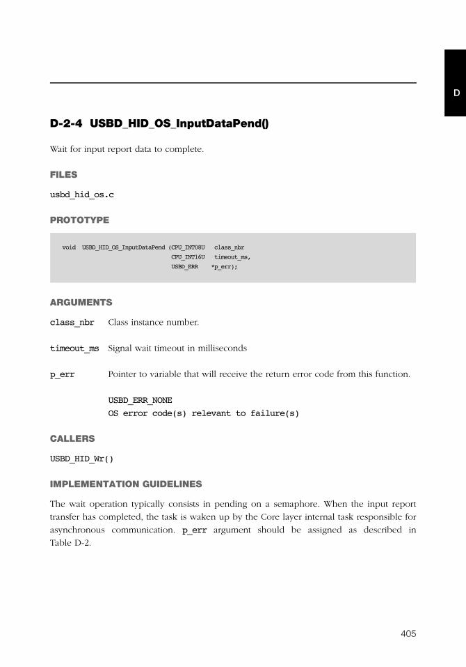
405
D
D-2-4 USBD_HID_OS_InputDataPend()
Wait for input report data to complete.
FILES
usbd_hid_os.c
PROTOTYPE
ARGUMENTS
class_nbr Class instance number.
timeout_ms Signal wait timeout in milliseconds
p_err Pointer to variable that will receive the return error code from this function.
USBD_ERR_NONE
OS error code(s) relevant to failure(s)
CALLERS
USBD_HID_Wr()
IMPLEMENTATION GUIDELINES
The wait operation typically consists in pending on a semaphore. When the input report
transfer has completed, the task is waken up by the Core layer internal task responsible for
asynchronous communication. p_err argument should be assigned as described in
Table D-2.
void USBD_HID_OS_InputDataPend (CPU_INT08U class_nbr
CPU_INT16U timeout_ms,
USBD_ERR *p_err);
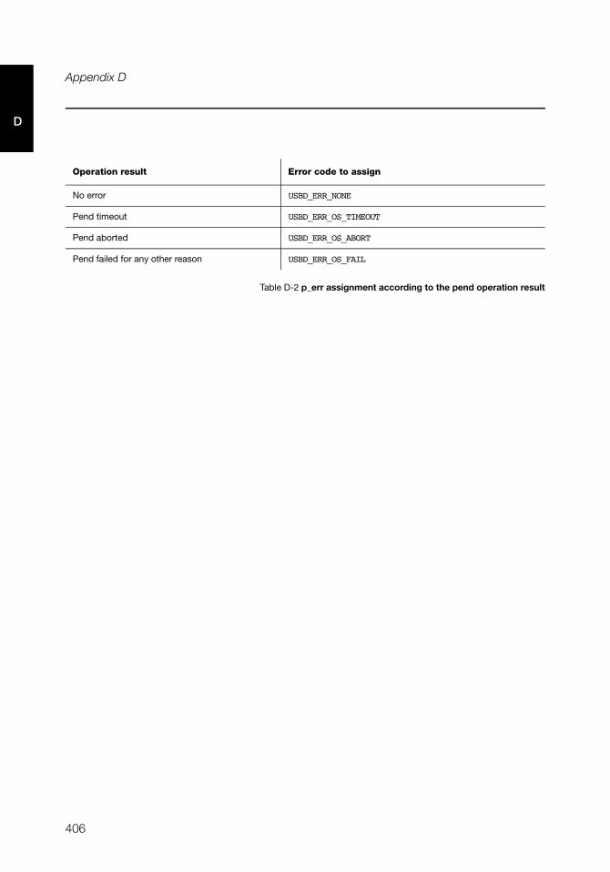
406
Appendix D
D
Table D-2 p_err assignment according to the pend operation result
Operation result Error code to assign
No error USBD_ERR_NONE
Pend timeout USBD_ERR_OS_TIMEOUT
Pend aborted USBD_ERR_OS_ABORT
Pend failed for any other reason USBD_ERR_OS_FAIL

407
D
D-2-5 USBD_HID_OS_InputDataPendAbort()
Abort any operation on input report.
FILES
usbd_hid_os.c
PROTOTYPE
ARGUMENTS
class_nbr Class instance number.
CALLERS
USBD_HID_WrSyncCmpl()
IMPLEMENTATION GUIDELINES
If the input report transfer completes with an error, the task waiting is waken up by
aborting the active wait done with USBD_HID_OS_InputDataPend(). The active wait
abortion is executed by the Core layer internal task responsible for asynchronous
communication.
void USBD_HID_OS_InputDataPendAbort (CPU_INT08U class_nbr);
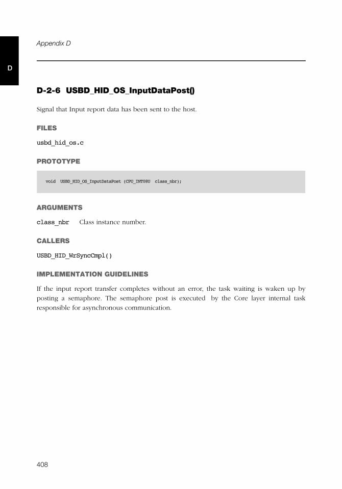
408
Appendix D
D
D-2-6 USBD_HID_OS_InputDataPost()
Signal that Input report data has been sent to the host.
FILES
usbd_hid_os.c
PROTOTYPE
ARGUMENTS
class_nbr Class instance number.
CALLERS
USBD_HID_WrSyncCmpl()
IMPLEMENTATION GUIDELINES
If the input report transfer completes without an error, the task waiting is waken up by
posting a semaphore. The semaphore post is executed by the Core layer internal task
responsible for asynchronous communication.
void USBD_HID_OS_InputDataPost (CPU_INT08U class_nbr);

409
D
D-2-7 USBD_HID_OS_OutputLock()
Lock class output report.
FILES
usbd_hid_os.c
PROTOTYPE
ARGUMENTS
class_nbr Class instance number.
p_err Pointer to variable that will receive the return error code from this function.
USBD_ERR_NONE: OS error code(s) relevant to failure(s)
CALLERS
USBD_HID_Rd()
USBD_HID_RdAsync()
USBD_HID_ClassReq()
IMPLEMENTATION GUIDELINES
The lock operation typically consists in pending on a semaphore. If the semaphore is free,
the task continues normally its execution, otherwise it waits until another task releases the
semaphore. p_err argument should be assigned as described in Table D-3.
Table D-3 p_err assignment according to the pend operation result
void USBD_HID_OS_OutputLock (CPU_INT08U class_nbr,
USBD_ERR *p_err);
Operation result Error code to assign
No error USBD_ERR_NONE
Pend aborted USBD_ERR_OS_ABORT
Pend failed for any other reason USBD_ERR_OS_FAIL
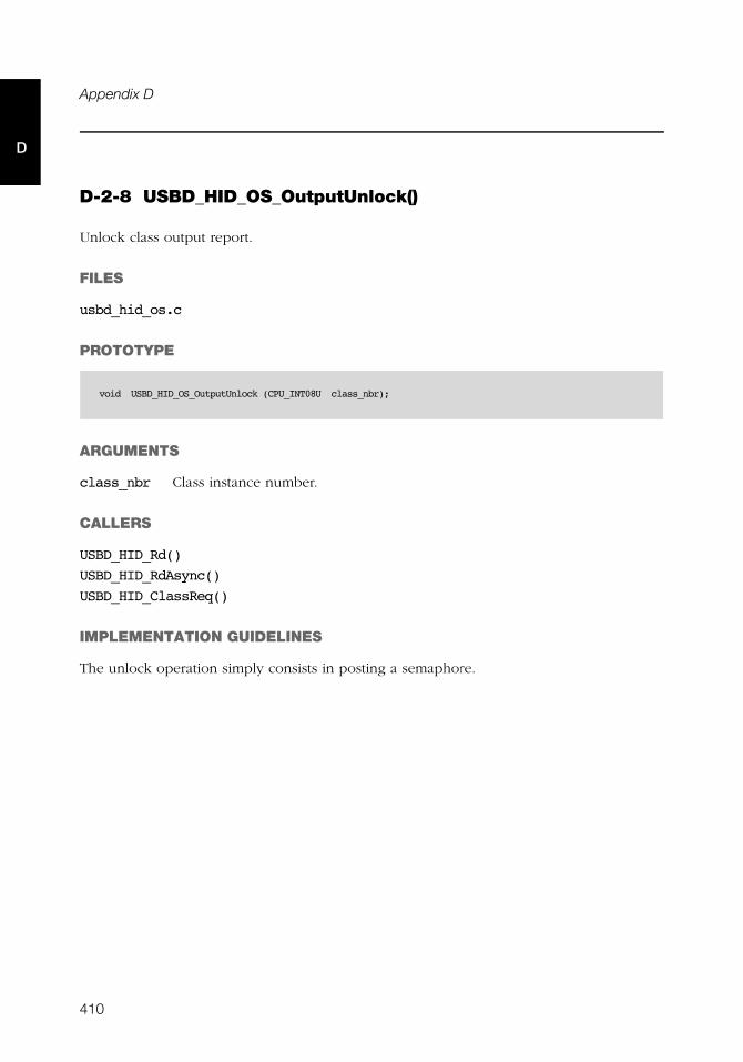
410
Appendix D
D
D-2-8 USBD_HID_OS_OutputUnlock()
Unlock class output report.
FILES
usbd_hid_os.c
PROTOTYPE
ARGUMENTS
class_nbr Class instance number.
CALLERS
USBD_HID_Rd()
USBD_HID_RdAsync()
USBD_HID_ClassReq()
IMPLEMENTATION GUIDELINES
The unlock operation simply consists in posting a semaphore.
void USBD_HID_OS_OutputUnlock (CPU_INT08U class_nbr);

411
D
D-2-9 USBD_HID_OS_OutputDataPend()
Wait for Output report data read completion.
FILES
usbd_hid_os.c
PROTOTYPE
ARGUMENTS
class_nbr Class instance number.
timeout_ms Signal wait timeout in milliseconds
p_err Pointer to variable that will receive the return error code from this function.
USBD_ERR_NONE
OS error code(s) relevant to failure(s)
CALLERS
USBD_HID_Rd()
IMPLEMENTATION GUIDELINES
The wait operation typically consists of pending on a semaphore. When the output report
transfer is complete, the task is woken up by the Core layer internal task responsible for
asynchronous communication. The p_err argument should be assigned as described in
Table D-2.
void USBD_HID_OS_OutputDataPend (CPU_INT08U class_nbr
CPU_INT16U timeout_ms,
USBD_ERR *p_err);
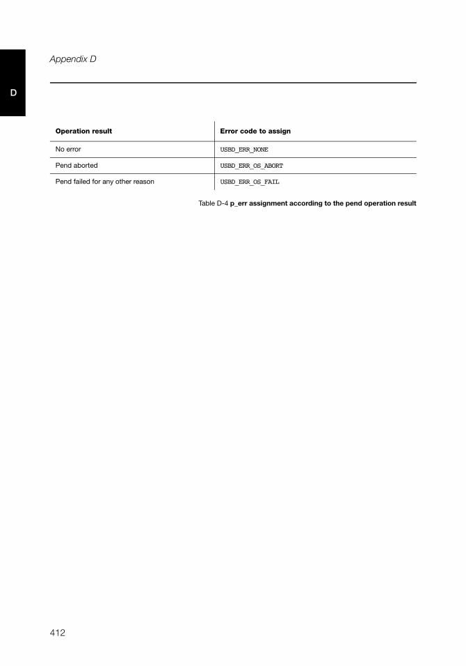
412
Appendix D
D
Table D-4 p_err assignment according to the pend operation result
Operation result Error code to assign
No error USBD_ERR_NONE
Pend aborted USBD_ERR_OS_ABORT
Pend failed for any other reason USBD_ERR_OS_FAIL
413
D
D-2-10 USBD_HID_OS_OutputDataPendAbort()
Abort the wait for Output report data read completion.
FILES
usbd_hid_os.c
PROTOTYPE
ARGUMENTS
class_nbr Class instance number.
CALLERS
USBD_HID_OutputDataCmpl()
IMPLEMENTATION GUIDELINES
If the output report transfer completes with an error, the task waiting is waken up by
aborting the active wait done with USBD_HID_OS_OutputDataPend(). The active wait
abortion is executed by the Core layer internal task responsible for asynchronous
communication.
void USBD_HID_OS_OutputDataPendAbort (CPU_INT08U class_nbr);

414
Appendix D
D
D-2-11 USBD_HID_OS_OutputDataPost()
Signal that Output report data has been received from the host
FILES
usbd_hid_os.c
PROTOTYPE
ARGUMENTS
class_nbr Class instance number.
CALLERS
USBD_HID_OutputDataCmpl()
IMPLEMENTATION GUIDELINES
If the output report transfer completes without an error, the task waiting is waken up by
posting a semaphore. The semaphore post is executed by the Core layer internal task
responsible for asynchronous communication.
void USBD_HID_OS_OutputDataPost (CPU_INT08U class_nbr);
415
D
D-2-12 USBD_HID_OS_TxLock()
Lock class transmit.
FILES
usbd_hid_os.c
PROTOTYPE
ARGUMENTS
class_nbr Class instance number.
p_err Pointer to variable that will receive the return error code from this function.
USBD_ERR_NONE: OS error code(s) relevant to failure(s).
CALLERS
USBD_HID_Wr()
USBD_HID_WrAsync()
IMPLEMENTATION GUIDELINES
The lock operation typically consists in pending on a semaphore. If the semaphore is free,
the task continues normally its execution, otherwise it waits until another task releases the
semaphore. p_err argument should be assigned as described in Table D-5.
Table D-5 p_err assignment according to the pend operation result
void USBD_HID_OS_TxLock (CPU_INT08U class_nbr,
USBD_ERR *p_err);
Operation result Error code to assign
No error USBD_ERR_NONE
Pend aborted USBD_ERR_OS_ABORT
Pend failed for any other reason USBD_ERR_OS_FAIL

416
Appendix D
D
D-2-13 USBD_HID_OS_TxUnlock()
Unlock class transmit.
FILES
usbd_hid_os.c
PROTOTYPE
ARGUMENTS
class_nbr Class instance number.
CALLERS
USBD_HID_Wr()
USBD_HID_WrAsync()
IMPLEMENTATION GUIDELINES
The unlock operation simply consists in posting a semaphore.
void USBD_HID_OS_TxUnlock (CPU_INT08U class_nbr);
417
D
D-2-14 USBD_HID_OS_TmrTask()
Process periodic input reports according to idle duration set by the host with the SET_IDLE
request.
FILES
usbd_hid_os.c
PROTOTYPE
ARGUMENTS
p_arg Pointer to task initialization argument.
CALLERS
This is a task.
IMPLEMENTATION GUIDELINES
The task body is usually implemented as an infinite loop. The task should perform the
following steps:
■ Delay for 4 ms. This delay corresponds to the 4 ms unit used to express the idle
duration transported by the SET_IDLE request.
■ Call USBD_HID_Report_TmrTaskHandler() function defined in the HID parser module.
This function implements the periodic input reports processing.
static void USBD_HID_OS_TmrTask (void *p_arg);

418
Appendix D
D
419
Appendix
EMSC API Reference
This appendix provides a reference to the mass storage class API. Each user-accessible
service is presented following a category order (i.e. initialization and communication
categories). The following information is provided for each of the services:
■ A brief description
■ The function prototype
■ The filename of the source code
■ A description of the arguments passed to the function
■ A description of returned value(s)
■ Specific notes and warnings regarding use of the service.
420
Appendix E
E
E-1 MASS STORAGE CLASS FUNCTIONS
E-1-1 USBD_MSC_Init()
Initialize internal structures and local global variables used by the MSC bulk only transport.
FILES
usbd_msc.h / usbd_msc.c
PROTOTYPE
ARGUMENTS
p_err Pointer to variable that will receive the return error code from this
function: USBD_ERR_NONE
RETURNED VALUE
None.
CALLERS
Application.
NOTES / WARNINGS
None.
void USBD_MSC_Init (USBD_ERR *p_err);
421
E
E-1-2 USBD_MSC_Add()
Create a new instance of the MSC.
FILES
usbd_msc.h / usbd_msc.c
PROTOTYPE
ARGUMENTS
p_err Pointer to variable that will receive the return error code from this
function.
USBD_ERR_NONE
USBD_ERR_ALLOC
RETURNED VALUE
Class instance number, if NO error(s).
USBD_CLASS_NBR_NONE, otherwise.
CALLERS
Application.
NOTES / WARNINGS
None.
CPU_INT08U USBD_MSC_Add ( USBD_ERR *p_err)
422
Appendix E
E
E-1-3 USBD_MSC_CfgAdd()
Add an existing MSC instance to the specified configuration and device. The MSC instance
was previously created by the function USBD_MSC_Add().
FILES
usbd_msc.h / usbd_msc.c
PROTOTYPE
ARGUMENTS
class_nbr MSC instance number.
dev_nbr Device number.
cfg_nbr Configuration index to add MSC instance to.
p_err Pointer to variable that will receive the return error code from this
function.
USBD_ERR_NONE
USBD_ERR_INVALID_ARG
USBD_ERR_ALLOC
USBD_ERR_NULL_PTR
USBD_ERR_DEV_INVALID_NBR
USBD_ERR_DEV_INVALID_STATE
USBD_ERR_CFG_INVALID_NBR
USBD_ERR_IF_ALLOC
USBD_ERR_IF_ALT_ALLOC
USBD_ERR_IF_INVALID_NBR
USBD_ERR_EP_NONE_AVAIL
USBD_ERR_EP_ALLOC
CPU_BOOLEAN USBD_MSC_CfgAdd (CPU_INT08U class_nbr,
CPU_INT08U dev_nbr,
CPU_INT08U cfg_nbr,
USBD_ERR *p_err);
423
ERETURNED VALUE
DEF_YES, if MSC instance is added to USB device configuration successfully.
DEF_NO, otherwise.
CALLERS
Application.
NOTES / WARNINGS
USBD_MSC_CfgAdd() basically adds an Interface descriptor and its associated Endpoint
descriptor(s) to the Configuration descriptor. One call to USBD_MSC_CfgAdd() builds the
Configuration descriptor corresponding to a MSC device with the following format:
Configuration Descriptor
|-- Interface Descriptor (MSC)
|-- Endpoint Descriptor (Bulk OUT)
|-- Endpoint Descriptor (Bulk IN)
If USBD_MSC_CfgAdd() is called several times from the application, it allows to create
multiple instances and multiple configurations. For instance, the following architecture
could be created for an high-speed device:
High-speed
|-- Configuration 0
|-- Interface 0 (MSC 0)
|-- Configuration 1
|-- Interface 0 (MSC 0)
|-- Interface 1 (MSC 1)
In that example, there are two instances of MSC: 'MSC 0' and 'MSC 1', and two possible
configurations for the device: 'Configuration 0' and 'Configuration 1'. 'Configuration 1' is
composed of two interfaces. Each class instance has an association with one of the
interfaces. If 'Configuration 1' is activated by the host, it allows the host to access two
different functionalities offered by the device.
424
Appendix E
E
E-1-4 USBD_MSC_LunAdd()
Add a logical unit number to the MSC interface.
FILES
usbd_msc.h / usbd_msc.c
PROTOTYPE
ARGUMENTS
p_store_name Pointer to logical unit driver.
class_nbr MSC instance number.
p_vend_id Pointer to string containing vendor id.
p_prod_id Pointer to string containing product id.
prod_rev_level Product revision level.
rd_only Boolean specifying if logical unit is read only or not.
p_err Pointer to variable that will receive the return error code from this
function.
USBD_ERR_NONE
USBD_ERR_INVALID_ARG
USBD_ERR_MSC_MAX_LUN_EXCEED
USBD_ERR_SCSI_LOG_UNIT_NOTRDY
void USBD_MSC_LunAdd (CPU_CHAR *p_store_name,
CPU_INT08U class_nbr,
CPU_CHAR *p_vend_id,
CPU_CHAR *p_prod_id,
CPU_INT32U prod_rev_level,
CPU_BOOLEAN rd_only,
USBD_ERR *p_err);
425
ERETURNED VALUE
None.
CALLERS
Application.
NOTES / WARNINGS
The pointer to logical unit driver specifies the type and volume of the logical unit to add.
Valid logical unit driver names follow the pattern:
<device_driver_name>:<logical_unit_number>:
where <device_driver_name> is the name of the device driver and
<logical_unit_number> is the device’s logical unit number. Take special note that the
logical unit number starts counting from number 0.
426
Appendix E
E
E-1-5 USBD_MSC_IsConn()
Get MSC connection state of the device.
FILES
usbd_msc.h / usbd_msc.c
PROTOTYPE
ARGUMENTS
class_nbr MSC instance number.
RETURNED VALUE
DEF_YES, if MSC is connected.
DEF_NO, otherwise.
CALLERS
Application.
NOTES / WARNINGS
USBD_MSC_IsConn() is typically used to verify that the device is in ‘configured’ state and that
the MSC instance is ready for communication. The following code illustrates a typical example:
Once the connected status is DEF_YES, the communication can start.
CPU_BOOLEAN USBD_MSC_IsConn (CPU_INT08U class_nbr);
CPU_BOOLEAN conn;
conn = USBD_MSC_IsConn(class_nbr);
if (conn != DEF_YES) {
USBD_MSC_OS_EnumSignalPend((CPU_INT16U)0,
&os_err);
}
427
E
E-1-6 USBD_MSC_TaskHandler()
Task to handle transfers for the MSC bulk-only transport protocol.
FILES
usbd_msc.h / usbd_msc.c
PROTOTYPE
ARGUMENTS
class_nbr MSC instance number.
RETURNED VALUE
None.
CALLERS
OS layer.
NOTES / WARNINGS
None.
void USBD_MSC_TaskHandler (CPU_INT08U class_nbr);
428
Appendix E
E
E-2 MSC OS FUNCTIONS
E-2-1 USBD_MSC_OS_Init()
Initialize MSC OS interface.
FILES
usbd_msc_os.h / usbd_msc_os.c
PROTOTYPE
ARGUMENTS
p_err Pointer to variable that will receive the return error code from this
function.
USBD_ERR_NONE
USBD_ERR_OS_FAIL
RETURNED VALUE
None.
CALLERS
USBD_OS_Init()
IMPLEMENTATION GUIDELINES
Initialization of the MSC OS interface must include creating:
1. Two semaphores, one for MSC communication and one for enumeration.
2. A MSC task to handle the MSC protocol.
void USBD_MSC_OS_Init (USBD_ERR *p_err)

429
E
E-2-2 USBD_MSC_OS_CommSignalPost()
Post a semaphore used for MSC communication.
FILES
usbd_msc_os.h / usbd_msc_os.c
PROTOTYPE
ARGUMENTS
class_nbr MSC instance class number.
p_err Pointer to variable that will receive the return error code from this
function.
USBD_ERR_NONE
USBD_ERR_OS_FAIL
RETURNED VALUE
None.
CALLERS
Various.
NOTES / WARNINGS
None.
void USBD_MSC_OS_CommSignalPost (CPU_INT08U class_nbr,
USBD_ERR *p_err)
430
Appendix E
E
E-2-3 USBD_MSC_OS_CommSignalPend()
Wait on a semaphore to become available for MSC communication.
FILES
usbd_msc_os.h / usbd_msc_os.c
PROTOTYPE
ARGUMENTS
class_nbr MSC instance class number.
timeout Timeout in milliseconds.
p_err Pointer to variable that will receive the return error code from this
function.
USBD_ERR_NONE
USBD_ERR_OS_TIMEOUT
USBD_ERR_OS_FAIL
RETURNED VALUE
None.
CALLERS
Various.
NOTES / WARNINGS
None.
void USBD_MSC_OS_CommSignalPend (CPU_INT08U class_nbr,
CPU_INT32U timeout,
USBD_ERR *p_err);
431
E
E-2-4 USBD_MSC_OS_CommSignalDel()
Delete a semaphore if no tasks are waiting on it for MSC communication.
FILES
usbd_msc_os.h / usbd_msc_os.c
PROTOTYPE
ARGUMENTS
class_nbr MSC instance class number.
p_err Pointer to variable that will receive the return error code from this
function.
USBD_ERR_NONE
USBD_ERR_OS_FAIL
RETURNED VALUE
None.
CALLERS
Various.
NOTES / WARNINGS
None.
void USBD_MSC_OS_CommSignalDel (CPU_INT08U class_nbr,
USBD_ERR *p_err);
432
Appendix E
E
E-2-5 USBD_MSC_OS_EnumSignalPost()
Post a semaphore for MSC enumeration process.
FILES
usbd_msc_os.h / usbd_msc_os.c
PROTOTYPE
ARGUMENTS
p_err Pointer to variable that will receive the return error code from this
function.
USBD_ERR_NONE
USBD_ERR_OS_FAIL
RETURNED VALUE
None.
CALLERS
Various.
NOTES / WARNINGS
None.
void USBD_MSC_OS_EnumSignalPost (USBD_ERR *p_err);
433
E
E-2-6 USBD_MSC_OS_EnumSignalPend()
Wait on a semaphore to become available for MSC enumeration process.
FILES
usbd_msc_os.h / usbd_msc_os.c
PROTOTYPE
ARGUMENTS
timeout Timeout in milliseconds.
p_err Pointer to variable that will receive the return error code from this
function.
USBD_ERR_NONE
USBD_ERR_OS_TIMEOUT
USBD_ERR_OS_FAIL
RETURNED VALUE
None.
CALLERS
Various.
NOTES / WARNINGS
None.
void USBD_MSC_OS_EnumSignalPend (CPU_INT32U timeout,
USBD_ERR *p_err);
434
Appendix E
E
E-3 MSC STORAGE LAYER FUNCTIONS
E-3-1 USBD_StorageInit()
Initialize internal structures and local global variables used by the storage medium.
FILES
usbd_storage.h / usbd_storage.c
PROTOTYPE
ARGUMENTS
p_storage_lun Pointer to logical unit storage structure.
p_err Pointer to variable that will receive the return error code from this
function.
USBD_ERR_NONE
USBD_ERR_MEDIUM_NOT_PRESENT
USBD_ERR_SCSI_LOG_UNIT_NOTRDY
USBD_ERR_SCSI_LOG_UNIT_NOTSUPPORTED
USBD_ERR_SCSI_LOG_UNIT_BUSY
RETURNED VALUE
None.
CALLERS
USBD_SCSI_Init()
NOTES / WARNINGS
None.
void USBD_StorageInit (USBD_STORAGE_LUN *p_storage_lun);
USBD_ERR *p_err)
435
E
E-3-2 USBD_StorageCapacityGet()
Get the capacity of the storage medium.
FILES
usbd_storage.h / usbd_storage.c
PROTOTYPE
ARGUMENTS
p_storage_lun Pointer to logical unit storage structure.
p_nbr_blks Pointer to variable that will receive the number of logical blocks.
p_blk_size Pointer to variable that will receive the size of each block, in bytes.
p_err Pointer to variable that will receive the return error code from this
function.
USBD_ERR_SCSI_MEDIUM_NOTPRESENT
USBD_ERR_NONE
RETURNED VALUE
None.
CALLERS
USBD_SCSI_IssueCmd()
NOTES / WARNINGS
None.
void USBD_StorageCapacityGet (USBD_STORAGE_LUN *p_storage_lun),
CPU_INT64U *p_nbr_blks,
CPU_INT32U *p_blk_size,
USBD_ERR *p_err)
436
Appendix E
E
E-3-3 USBD_StorageRd()
Read data from the storage medium.
FILES
usbd_storage.h / usbd_storage.c
PROTOTYPE
ARGUMENTS
p_storage_lun Pointer to the logical unit storage structure.
blk_addr Logical Block Address (LBA) of read block start.
nbr_blks Number of logical blocks to read.
p_data_buf Pointer to buffer in which data will be stored.
p_err Pointer to variable that will receive the return error code from this function.
USBD_ERR_NONE
USBD_ERR_SCSI_MEDIUM_NOT_PRESENT
RETURNED VALUE
None.
CALLERS
USBD_SCSI_RdData()
NOTES / WARNINGS
None.
void USBD_StorageRd (USBD_STORAGE_LUN *p_storage_lun,
CPU_INT32U blk_addr,
CPU_INT32U nbr_blks,
CPU_INT08U *p_data_buf,
USBD_ERR *p_err);
437
E
E-3-4 USBD_StorageWr()
Write data to the storage medium.
FILES
usbd_storage.h / usbd_storage.c
PROTOTYPE
ARGUMENTS
p_storage_lun Pointer to logical unit storage structure
blk_addr Logical Block Address (LBA) of write block start.
nbr_blks Number of logical blocks to write.
p_data_buf Pointer to buffer in which data is stored.
p_err Pointer to variable that will receive the return error code from this
function.
USBD_ERR_NONE
USBD_ERR_SCSI_MEDIUM_NOTPRESENT
RETURNED VALUE
None.
CALLERS
USBD_SCSI_WrData()
void USBD_StorageWr (USBD_STORAGE_LUN *p_storage_lun,
CPU_INT32U blk_addr,
CPU_INT32U nbr_blks,
CPU_INT08U *p_data_buf,
USBD_ERR *p_err);

438
Appendix E
ENOTES / WARNINGS
None.
439
E
E-3-5 USBD_StorageStatusGet()
Get the presence of the storage medium.
FILES
usbd_storage.h / usbd_storage.c
PROTOTYPE
ARGUMENTS
p_storage_lun Pointer to logical unit storage structure
p_err Pointer to variable that will receive the return error code from this
function.
USBD_ERR_NONE
USBD_ERR_SCSI_MEDIUM_NOTPRESENT
USBD_ERR_SCSI_MEDIUM_NOT_RDY_TO_RDY
USBD_ERR_SCSI_MEDIUM_RDY_TO_NOT_RDY
RETURNED VALUE
None.
CALLERS
USBD_SCSI_IssueCmd()
NOTES / WARNINGS
None.
void USBD_StorageStatusGet (USBD_STORAGE_LUN *p_storage_lun,
USBD_ERR *p_err);

440
Appendix E
E
441
Appendix
FPHDC API Reference
This appendix provides a reference to the Personal Healthcare Device Class (PHDC) API.
Each user-accessible service is presented following a category order (i.e. initialization,
communication and RTOS layer categories). The following information is provided for each
of the services:
■ A brief description
■ The function prototype
■ The filename of the source code
■ A description of the arguments passed to the function
■ A description of returned value(s)
Specific notes and warnings regarding use of the service.
442
Appendix F
F F-1 PHDC FUNCTIONS
F-1-1 USBD_PHDC_Init()
Initialize internal structures and local global variables used by the PHDC.
FILES
usbd_phdc.h / usbd_phdc.c
PROTOTYPE
ARGUMENTS
p_err Pointer to variable that will receive the return error code from this
function.
USBD_ERR_NONE
RETURNED VALUE
None.
CALLERS
Application.
NOTES / WARNINGS
None.
void USBD_PHDC_Init (USBD_ERR *p_err);
443
FF-1-2 USBD_PHDC_Add()
Create a new instance of the PHDC.
FILES
usbd_phdc.h / usbd_phdc.c
PROTOTYPE
ARGUMENTS
data_fmt_11073 Variable that indicates whether the class instance uses IEEE
11073 or a vendor-defined data format.
DEF_YES Class instance uses IEEE 11073 data format.
DEF_NO Class instance uses vendor-defined data format.
preamble_capable Variable that indicates whether the class instance support
metadata message preamble or not.
DEF_YES Class instance support metadata message preamble.
DEF_NO Class instance doesn’t support metadata message
preamble.
preamble_en_notify Pointer to a callback function that will notify the application if
the host enable / disable metadata message preamble.
low_latency_interval Interrupt endpoint interval in frames or microframes. Can be 0 if
PHDC device will not send low latency data.
CPU_INT08U USBD_PHDC_Add (CPU_BOOLEAN data_fmt_11073,
CPU_BOOLEAN preamble_capable,
USBD_PHDC_PREAMBLE_EN_NOTIFY preamble_en_notify,
CPU_INT16U low_latency_interval,
USBD_ERR *p_err)
444
Appendix F
F p_err Pointer to variable that will receive the return error code from this
function.
USBD_ERR_NONE
USBD_ERR_ALLOC
RETURNED VALUE
Class instance number, if NO error(s).
USBD_CLASS_NBR_NONE, otherwise.
CALLERS
Application.
NOTES / WARNINGS
None.
445
FF-1-3 USBD_PHDC_CfgAdd()
Add a PHDC instance into the specified configuration. The PHDC instance was previously
created by the function USBD_PHDC_Add().
FILES
usbd_phdc.h / usbd_phdc.c
PROTOTYPE
ARGUMENTS
class_nbr PHDC instance number.
dev_nbr Device number.
cfg_nbr Configuration index to add PHDC instance to.
p_err Pointer to variable that will receive the return error code from this
function.
USBD_ERR_NONE
USBD_ERR_INVALID_ARG
USBD_ERR_ALLOC
USBD_ERR_NULL_PTR
USBD_ERR_DEV_INVALID_NBR
USBD_ERR_DEV_INVALID_STATE
USBD_ERR_CFG_INVALID_NBR
USBD_ERR_IF_ALLOC
USBD_ERR_IF_ALT_ALLOC
USBD_ERR_IF_INVALID_NBR
USBD_ERR_EP_NONE_AVAIL
USBD_ERR_EP_ALLOC
void USBD_PHDC_CfgAdd (CPU_INT08U class_nbr,
CPU_INT08U dev_nbr,
CPU_INT08U cfg_nbr,
USBD_ERR *p_err);
446
Appendix F
F RETURNED VALUE
None.
CALLERS
Application.
NOTES / WARNINGS
USBD_PHDC_CfgAdd() basically adds an Interface descriptor and its associated Endpoint
descriptor(s) to the Configuration descriptor. One call to USBD_PHDC_CfgAdd() builds the
Configuration descriptor corresponding to a PHDC device with the following format:
Configuration Descriptor
|-- Interface Descriptor (PHDC)
|-- Endpoint Descriptor (Bulk OUT)
|-- Endpoint Descriptor (Bulk IN)
|-- Endpoint Descriptor (Interrupt IN) - optional
The Interrupt IN endpoint is optional. It will be added to the Interface descriptor if
application specified that it will send low latency data when calling USBD_PHDC_WrCfg().
If USBD_PHDC_CfgAdd() is called several times from the application, it allows to create
multiple instances and multiple configurations. For instance, the following architecture
could be created for an high-speed device:
High-speed
|-- Configuration 0
|-- Interface 0 (PHDC 0)
|-- Configuration 1
|-- Interface 0 (PHDC 0)
|-- Interface 1 (PHDC 1)
In that example, there are two instances of PHDC: 'PHDC 0' and 'PHDC 1', and two possible
configurations for the device: 'Configuration 0' and 'Configuration 1'. 'Configuration 1' is
composed of two interfaces. Each class instance has an association with one of the
interfaces. If 'Configuration 1' is activated by the host, it allows the host to access two
different functionalities offered by the device.
447
FF-1-4 USBD_PHDC_IsConn()
Get PHDC connection state.
FILES
usbd_phdc.h / usbd_phdc.c
PROTOTYPE
ARGUMENTS
class_nbr PHDC instance number.
RETURNED VALUE
DEF_YES, if PHDC is connected.
DEF_NO, otherwise.
CALLERS
Application.
NOTES / WARNINGS
USBD_PHDC_IsConn() is typically used to verify that the device is in ‘configured’ state and that
the PHDC instance is ready for communication. The following code illustrates a typical example:
Once the connected status is DEF_YES, the communication can start.
CPU_BOOLEAN USBD_PHDC_IsConn (CPU_INT08U class_nbr);
CPU_BOOLEAN conn;
conn = USBD_PHDC_IsConn(class_nbr);
while (conn != DEF_YES) {
OSTimeDlyHMSM(0, 0, 0, 250);
conn = USBD_PHDC_IsConn(class_nbr);
}

448
Appendix F
F F-1-5 USBD_PHDC_RdCfg()
Initialize read communication pipe parameters.
FILES
usbd_phdc.h / usbd_phdc.c
PROTOTYPE
ARGUMENTS
class_nbr PHDC instance number.
latency_rely Bitmap of transfer latency / reliability that this communication pipe will
carry. Can be one or more of these values:
USBD_PHDC_LATENCY_VERYHIGH_RELY_BEST
USBD_PHDC_LATENCY_HIGH_RELY_BEST
USBD_PHDC_LATENCY_MEDIUM_RELY_BEST
p_data_opaque Pointer to a buffer that contains opaque data related to this
communication pipe.
data_opaque_len Length of opaque data (in octets). If 0, no metadata descriptor will be
written for the endpoint.
p_err Pointer to variable that will receive the return error code from this
function.
USBD_ERR_NONE
USBD_ERR_NULL_PTR
USBD_ERR_INVALID_ARG
void USBD_PHDC_RdCfg (CPU_INT08U class_nbr,
LATENCY_RELY_FLAGS latency_rely,
CPU_INT08U *p_data_opaque,
CPU_INT08U data_opaque_len,
USBD_ERR *p_err);
449
FRETURNED VALUE
None.
CALLERS
Application.
NOTES / WARNINGS
USBD_PHDC_RdCfg() should be called after USBD_PHDC_Init() and USBD_PHDC_Add() but
before USBD_PHDC_CfgAdd().
450
Appendix F
F F-1-6 USBD_PHDC_WrCfg()
Initialize write communication pipe parameters.
FILES
usbd_phdc.h / usbd_phdc.c
PROTOTYPE
ARGUMENTS
class_nbr PHDC instance number.
latency_rely Bitmap of transfer Latency / reliability that this communication pipe will
carry. Can be one or more of these values:
USBD_PHDC_LATENCY_VERYHIGH_RELY_BEST
USBD_PHDC_LATENCY_HIGH_RELY_BEST
USBD_PHDC_LATENCY_MEDIUM_RELY_BEST
USBD_PHDC_LATENCY_MEDIUM_RELY_BETTER
USBD_PHDC_LATENCY_MEDIUM_RELY_GOOD
USBD_PHDC_LATENCY_LOW_RELY_GOOD
p_data_opaque Pointer to a buffer that contains opaque data related to this
communication pipe.
data_opaque_len Length of opaque data (in octets). If 0, no metadata descriptor will be
written for the endpoint.
void USBD_PHDC_WrCfg (CPU_INT08U class_nbr,
LATENCY_RELY_FLAGS latency_rely,
CPU_INT08U *p_data_opaque,
CPU_INT08U data_opaque_len,
USBD_ERR *p_err);
451
Fp_err Pointer to variable that will receive the return error code from this
function.
USBD_ERR_NONE
USBD_ERR_NULL_PTR
USBD_ERR_INVALID_ARG
RETURNED VALUE
None.
CALLERS
Application.
NOTES / WARNINGS
USBD_PHDC_WrCfg() should be called after USBD_PHDC_Init() and USBD_PHDC_Add() but
before USBD_PHDC_CfgAdd().
Since low latency transfers will use a different endpoint, it is possible to set different opaque
data for that endpoint. In case the application need different opaque data for low latency
pipe, USBD_PHDC_WrCfg() should be called twice. Once with all the desired latency/
reliability flags set except for low latency, opaque data passed at this call will be used for
the Bulk endpoint metadata descriptor. USBD_PHDC_WrCfg() should then be called once
again with only the low latency flag set, opaque data passed at this call will be used for
interrupt endpoint metadata descriptor.
452
Appendix F
F F-1-7 USBD_PHDC_11073_ExtCfg()
Configure function extension for given class instance.
FILES
usbd_phdc.h / usbd_phdc.c
PROTOTYPE
ARGUMENTS
class_nbr PHDC instance number.
p_dev_specialization Pointer to an array that contains a list of device
specializations.
nbr_dev_specialization Number of device specializations specified in
p_dev_specialization.
p_err Pointer to variable that will receive the return error code from this
function.
USBD_ERR_NONE
USBD_ERR_INVALID_ARG
RETURNED VALUE
None.
CALLERS
Application.
void USBD_PHDC_11073_ExtCfg (CPU_INT08U class_nbr,
CPU_INT16U *p_dev_specialization,
CPU_INT08U nbr_dev_specialization,
USBD_ERR *p_err);
453
FNOTES / WARNINGS
USBD_PHDC_11073_ExtCfg() should be called only if PHDC instance uses 11073 data
format.
USBD_PHDC_11073_ExtCfg() should be called after USBD_PHDC_Init() and
USBD_PHDC_Add() but before USBD_PHDC_CfgAdd().
For more information on 11073 device specialization, See 'Personal Healthcare Device Class
specifications Revision 1.0', Appendix A. For a list of known device specialization, see
'Nomenclature code annex of ISO/IEEE 11073-20601'. Specific code are listed in the 'From
Communication infrastructure (MDC_PART_INFRA)' section.
454
Appendix F
F F-1-8 USBD_PHDC_RdPreamble()
Read metadata preamble. This function is blocking.
FILES
usbd_phdc.h / usbd_phdc.c
PROTOTYPE
ARGUMENTS
class_nbr PHDC instance number.
p_buf Pointer to buffer that will contain data from metadata message preamble.
buf_len Opaque data buffer length in octets.
p_nbr_xfer Pointer to a variable that will contain the number of transfer the
preamble will apply to. After this call, USBD_PHDC_Rd shall be called
nbr_xfer times by the application.
timeout Timeout in milliseconds.
p_err Pointer to variable that will receive the return error code from this
function.
USBD_ERR_NONE
USBD_ERR_INVALID_CLASS_STATE
USBD_ERR_INVALID_ARG
USBD_ERR_NULL_PTR
USBD_ERR_ALLOC
USBD_ERR_RX
CPU_INT08U USBD_PHDC_RdPreamble (CPU_INT08U class_nbr,
void *p_buf,
CPU_INT08U buf_len,
CPU_INT08U *p_nbr_xfer,
CPU_INT16U timeout,
USBD_ERR *p_err);
455
FUSBD_ERR_DEV_INVALID_NBR
USBD_ERR_EP_INVALID_NBR
USBD_ERR_DEV_INVALID_STATE
USBD_ERR_EP_INVALID_TYPE
USBD_OS_ERR_TIMEOUT
USBD_OS_ERR_ABORT
USBD_OS_ERR_FAIL
RETURNED VALUE
Length of opaque data read from metadata preamble, if no error.
0, otherwise
CALLERS
Application.
NOTES / WARNINGS
USBD_PHDC_RdPreamble() should always be called before USBD_PHDC_Rd() if metadata
message preambles are enabled by the host. Application should then call USBD_PHDC_Rd()
p_nbr_xfer times.
If host disable preamble while application is pending on this function, the call will
immediately return with error ‘USBD_OS_ERR_ABORT’.
456
Appendix F
F F-1-9 USBD_PHDC_Rd()
Read PHDC data. This function is blocking.
FILES
usbd_phdc.h / usbd_phdc.c
PROTOTYPE
ARGUMENTS
class_nbr PHDC instance number.
p_buf Pointer to buffer that will contain opaque data from metadata message
preamble.
buf_len Opaque data buffer length in octets.
timeout Timeout in milliseconds.
p_err Pointer to variable that will receive the return error code from this function.
USBD_ERR_NONEUSBD_ERR_INVALID_CLASS_STATEUSBD_ERR_INVALID_ARGUSBD_ERR_NULL_PTRUSBD_ERR_RXUSBD_ERR_DEV_INVALID_NBRUSBD_ERR_EP_INVALID_NBRUSBD_ERR_DEV_INVALID_STATEUSBD_ERR_EP_INVALID_TYPEUSBD_OS_ERR_TIMEOUTUSBD_OS_ERR_ABORTUSBD_OS_ERR_FAIL
CPU_INT08U USBD_PHDC_Rd (CPU_INT08U class_nbr,
void *p_buf,
CPU_INT16U buf_len,
CPU_INT16U timeout,
USBD_ERR *p_err);
457
FRETURNED VALUE
Number of octets received, if no error(s).
0, otherwise.
CALLERS
Application.
NOTES / WARNINGS
USBD_PHDC_Rd() should always be called after USBD_PHDC_RdPreamble() if metadata
message preambles are enabled by the host.
Application should ensure that the length of the buffer provided is large enough to
accommodate the incoming transfer. Otherwise, synchronization with metadata preambles
might be lost.
If host enable preamble while application is pending on this function, the call will
immediately return with error ‘USBD_OS_ERR_ABORT’.
458
Appendix F
F F-1-10 USBD_PHDC_Wrpreamble()
Write metadata preamble. This function is blocking.
FILES
usbd_phdc.h / usbd_phdc.c
PROTOTYPE
ARGUMENTS
class_nbr PHDC instance number.
p_data_opaque Pointer to buffer that will supply opaque data.
data_opaque_len Length of opaque data buffer in octets.
latency_rely Latency reliability of related transfers.
nbr_xfers Number of transfers this preamble will apply to.
timeout Timeout in milliseconds.
p_err Pointer to variable that will receive the return error code from this
function.
USBD_ERR_NONE
USBD_ERR_INVALID_ARG
USBD_ERR_NULL_PTR
USBD_ERR_TX
USBD_ERR_DEV_INVALID_NBR
void USBD_PHDC_WrPreamble (CPU_INT08U class_nbr,
void *p_data_opaque,
CPU_INT16U data_opaque_len,
LATENCY_RELY_FLAGS latency_rely
CPU_INT08U nbr_xfers,
CPU_INT16U timeout,
USBD_ERR *p_err);
459
FUSBD_ERR_DEV_INVALID_STATE
USBD_ERR_EP_INVALID_ADDR
USBD_ERR_EP_INVALID_STATE
USBD_ERR_EP_INVALID_TYPE
USBD_OS_ERR_TIMEOUT
USBD_OS_ERR_ABORT
USBD_OS_ERR_FAIL
RETURNED VALUE
None.
CALLERS
Application.
NOTES / WARNINGS
USBD_PHDC_WrPreamble() should always be called before USBD_PHDC_Wr() if metadata
message preambles are enabled by the host and if the latency of the transfer is not ‘low’.
Application will have to call USBD_PHDC_Wr() ‘nbr_xfers’ of times with the same latency
/ reliability parameter after a call to USBD_PHDC_WrPreamble().
460
Appendix F
F F-1-11 USBD_PHDC_Wr()
Write PHDC data. This function is blocking.
FILES
usbd_phdc.h / usbd_phdc.c
PROTOTYPE
ARGUMENTS
class_nbr PHDC instance number.
p_buf Pointer to buffer that will supply data.
buf_len Buffer length in octets.
latency_rely Latency / reliability of this transfer.
timeout Timeout in milliseconds.
p_err Pointer to variable that will receive the return error code from this
function.
USBD_ERR_NONE
USBD_ERR_INVALID_ARG
USBD_ERR_NULL_PTR
USBD_ERR_TX
USBD_ERR_INVALID_CLASS_STATE
USBD_ERR_DEV_INVALID_NBR
USBD_ERR_DEV_INVALID_STATE
USBD_ERR_EP_INVALID_ADDR
void USBD_PHDC_Wr (CPU_INT08U class_nbr,
void *p_buf,
CPU_INT16U buf_len,
LATENCY_RELY_FLAGS latency_rely
CPU_INT16U timeout,
USBD_ERR *p_err);

461
FUSBD_ERR_EP_INVALID_STATE
USBD_ERR_EP_INVALID_TYPE
USBD_OS_ERR_TIMEOUT
USBD_OS_ERR_ABORT
USBD_OS_ERR_FAIL
RETURNED VALUE
None.
CALLERS
Application.
NOTES / WARNINGS
USBD_PHDC_Wr() should always be called after USBD_PHDC_WrPreamble() if metadata
message preambles are enabled by the host and if the latency of the transfer is not ‘low’.
Application will have to call USBD_PHDC_Wr() ‘nbr_xfers’ of times with the same latency /
reliability parameter after a call to USBD_PHDC_WrPreamble().
462
Appendix F
F F-1-12 USBD_PHDC_Reset()
Reset PHDC instance.
FILES
usbd_phdc.h / usbd_phdc.c
PROTOTYPE
ARGUMENTS
class_nbr PHDC instance number.
RETURNED VALUE
None.
CALLERS
USBD_PHDC_Disconn() and Application.
NOTES / WARNINGS
USBD_PHDC_Reset() should be used to reset internal variables like the transmit priority
queue of the PHDC instance.
This function should be called when the data layer above PHDC request to terminate
communication. For instance, USBD_PHDC_Reset() should be called when the host send an
‘11073 Association abort’ request.
void USBD_PHDC_Reset (CPU_INT08U class_nbr);
463
FF-2 PHDC OS LAYER FUNCTIONS
F-2-1 USBD_PHDC_OS_Init()
Initialize PHDC OS layer.
FILES
usbd_phdc_os.h / usbd_phdc_os.c
PROTOTYPE
ARGUMENTS
p_err Pointer to variable that will receive the return error code from this
function.
RETURNED VALUE
None.
CALLERS
USBD_PHDC_Init()
IMPLEMENTATION GUIDELINES
This function should be used to initialize all RTOS layer’s internal variables / tasks of every
class instances. It will be called only once.
In case creation of semaphore, mutex, or other signal fails, the function should assign
USBD_ERR_OS_SIGNAL_CREATE to p_err and return immediately. If any other error occurs,
USBD_ERR_OS_INIT_FAIL should be assigned to p_err. Otherwise, USBD_ERR_NONE should
be used.
void USBD_PHDC_OS_Init (USBD_ERR *p_err);
464
Appendix F
F F-2-2 USBD_PHDC_OS_RdLock()
Lock the read pipe.
FILES
usbd_phdc_os.h / usbd_phdc_os.c
PROTOTYPE
ARGUMENTS
class_nbr PHDC instance number.
timeout Timeout.
p_err Pointer to variable that will receive the return error code from this
function.
RETURNED VALUE
None.
CALLERS
USBD_PHDC_Rd(), USBD_PHDC_RdPreamble()
IMPLEMENTATION GUIDELINES
Typical implementation will consist in pending on a semaphore that locks the read pipe.
p_err argument should be assigned as described in Table F-1.
void USBD_PHDC_OS_RdLock (CPU_INT08U class_nbr,
CPU_INT16U timeout,
USBD_ERR *p_err);
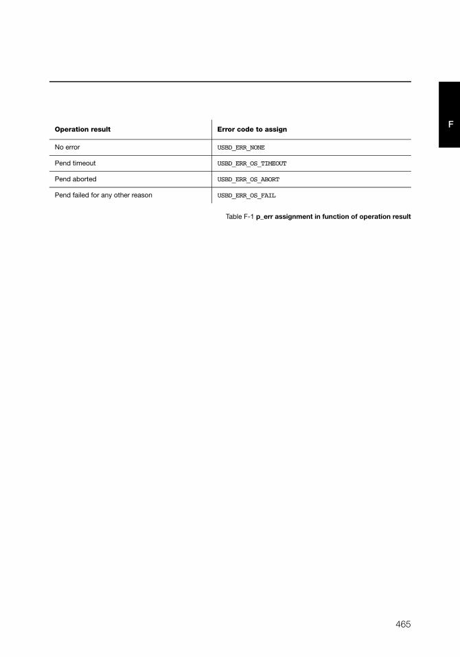
465
F
Table F-1 p_err assignment in function of operation result
Operation result Error code to assign
No error USBD_ERR_NONE
Pend timeout USBD_ERR_OS_TIMEOUT
Pend aborted USBD_ERR_OS_ABORT
Pend failed for any other reason USBD_ERR_OS_FAIL
466
Appendix F
F F-2-3 USBD_PHDC_OS_RdUnLock()
Unlock the read pipe.
FILES
usbd_phdc_os.h / usbd_phdc_os.c
PROTOTYPE
ARGUMENTS
class_nbr PHDC instance number.
RETURNED VALUE
None.
CALLERS
USBD_PHDC_Rd(), USBD_PHDC_RdPreamble()
IMPLEMENTATION GUIDELINES
Typical implementation will consist in posting a semaphore that locks the read pipe.
void USBD_PHDC_OS_RdUnlock (CPU_INT08U class_nbr);
467
FF-2-4 USBD_PHDC_OS_WrIntrLock()
Lock the write interrupt pipe.
FILES
usbd_phdc_os.h / usbd_phdc_os.c
PROTOTYPE
ARGUMENTS
class_nbr PHDC instance number.
timeout Timeout.
p_err Pointer to variable that will receive the return error code from this
function.
RETURNED VALUE
None.
CALLERS
USBD_PHDC_Wr()
IMPLEMENTATION GUIDELINES
Typical implementation will consist in pending on a semaphore that locks the write
interrupt pipe.
p_err argument should be assigned as described in Table F-1.
void USBD_PHDC_OS_WrIntrLock (CPU_INT08U class_nbr,
CPU_INT16U timeout,
USBD_ERR *p_err);
468
Appendix F
F F-2-5 USBD_PHDC_OS_WrIntrUnLock()
Unlock the write interrupt pipe.
FILES
usbd_phdc_os.h / usbd_phdc_os.c
PROTOTYPE
ARGUMENTS
class_nbr PHDC instance number.
RETURNED VALUE
None.
CALLERS
USBD_PHDC_Wr()
IMPLEMENTATION GUIDELINES
Typical implementation will consist in posting a semaphore that locks the write interrupt
pipe.
void USBD_PHDC_OS_WrIntrUnlock (CPU_INT08U class_nbr);
469
FF-2-6 USBD_PHDC_OS_WrBulkLock()
Lock the write bulk pipe.
FILES
usbd_phdc_os.h / usbd_phdc_os.c
PROTOTYPE
ARGUMENTS
class_nbr PHDC instance number.
prio Priority of the transfer. This value is between 0 and 4 and is computed in
function of the transfer’s QoS by the caller.
timeout Timeout.
p_err Pointer to variable that will receive the return error code from this
function.
RETURNED VALUE
None.
CALLERS
USBD_PHDC_Wr(), USBD_PHDC_WrPreamble().
void USBD_PHDC_OS_WrBulkLock (CPU_INT08U class_nbr,
CPU_INT08U prio,
CPU_INT16U timeout,
USBD_ERR *p_err);
470
Appendix F
F IMPLEMENTATION GUIDELINES
Two typical implementations will be possible here. The first one consists in pending on a
semaphore that locks the write bulk pipe, just as we saw previously.
But since different QoS data can travel using a single bulk IN endpoint, you might want to
prioritize them in function of the QoS. See section 11-4 “RTOS QoS-based scheduler” on
page 196 for more details on how a priority manager can be implemented.
p_err argument should be assigned as described in Table F-1.
471
FF-2-7 USBD_PHDC_OS_WrBulkUnLock()
Unlock the write bulk pipe.
FILES
usbd_phdc_os.h / usbd_phdc_os.c
PROTOTYPE
ARGUMENTS
class_nbr PHDC instance number.
RETURNED VALUE
None.
CALLERS
USBD_PHDC_Wr()
IMPLEMENTATION GUIDELINES
Two typical implementations will be possible here. The first one consists in posting the
semaphore that locks the write bulk pipe, if no priority management is implemented.
However, if priority management has been integrated, this call should release the scheduler
(See Section 11-4, “RTOS QoS-based scheduler” on page 196).
void USBD_PHDC_OS_WrBulkUnlock (CPU_INT08U class_nbr);

472
Appendix F
F
473
Appendix
GVendor Class API Reference
This appendix provides a reference to the Vendor class API. Each user-accessible service is
presented following a category order (i.e., initialization and communication categories). The
following information is provided for each of the services:
■ A brief description
■ The function prototype
■ The filename of the source code
■ A description of the arguments passed to the function
■ A description of returned value(s)
■ Specific notes and warnings regarding use of the service.
474
Appendix G
G
G-1 VENDOR CLASS FUNCTIONS
G-1-1 USBD_Vendor_Init()
Initialize internal structures and local global variables used by the Vendor class.
FILES
usbd_vendor.c
PROTOTYPE
ARGUMENTS
p_err Pointer to variable that will receive the return error code from this function.
USBD_ERR_NONE
RETURNED VALUE
None.
CALLERS
Application.
NOTES / WARNINGS
The initialization function must be called only once by the application, and before calling
any other Vendor API.
void USBD_Vendor_Init (USBD_ERR *p_err);
475
G
G-1-2 USBD_Vendor_Add()
Create a new instance of the Vendor class.
FILES
usbd_vendor.c
PROTOTYPE
ARGUMENTS
intr_en Interrupt endpoints IN and OUT flag:
DEF_TRUE Pair of interrupt endpoints added to interface.
DEF_FALSE Pair of interrupt endpoints not added to interface.
interval Endpoint interval in frames or microframes.
req_callback Vendor-specific request callback.
p_err Pointer to variable that will receive the return error code from this function.
USBD_ERR_NONE
USBD_ERR_INVALID_ARG
USBD_ERR_ALLOC
RETURNED VALUE
Class instance number, if NO error(s).
USBD_CLASS_NBR_NONE, otherwise.
CPU_INT08U USBD_Vendor_Add (CPU_BOOLEAN intr_en,
CPU_INT16U interval,
USBD_VENDOR_REQ_FNCT req_callback,
USBD_ERR *p_err);

476
Appendix G
G
CALLERS
Application.
NOTES / WARNINGS
None.
477
G
G-1-3 USBD_Vendor_CfgAdd()
Add a Vendor class instance into the specified configuration. The Vendor class instance was
previously created by the function USBD_Vendor_Add().
FILES
usbd_vendor.c
PROTOTYPE
ARGUMENTS
class_nbr Class instance number.
dev_nbr Device number.
cfg_nbr Configuration index to add Vendor class instance to.
p_err Pointer to variable that will receive the return error code from this function.
USBD_ERR_NONE
USBD_ERR_INVALID_ARG
USBD_ERR_ALLOC
USBD_ERR_NULL_PTR
USBD_ERR_DEV_INVALID_NBR
USBD_ERR_DEV_INVALID_STATE
USBD_ERR_CFG_INVALID_NBR
USBD_ERR_IF_ALLOC
USBD_ERR_IF_ALT_ALLOC
USBD_ERR_IF_INVALID_NBR
USBD_ERR_EP_NONE_AVAIL
USBD_ERR_EP_ALLOC
void USBD_Vendor_CfgAdd (CPU_INT08U class_nbr,
CPU_INT08U dev_nbr,
CPU_INT08U cfg_nbr,
USBD_ERR *p_err);
478
Appendix G
G
RETURNED VALUE
None.
CALLERS
Application.
NOTES / WARNINGS
USBD_Vendor_CfgAdd() basically adds an Interface descriptor and its associated Endpoint
descriptor(s) to the Configuration descriptor. One call to USBD_Vendor_CfgAdd() builds the
Configuration descriptor corresponding to a Vendor-specific device with the following format:
Configuration Descriptor
|-- Interface Descriptor (Vendor class)
|-- Endpoint Descriptor (Bulk OUT)
|-- Endpoint Descriptor (Bulk IN)
|-- Endpoint Descriptor (Interrupt OUT) - optional
|-- Endpoint Descriptor (Interrupt IN) - optional
The pair of Interrupt endpoints are optional. They can be added to the Interface descriptor
by setting the parameter intr_en to DEF_TRUE.
If USBD_Vendor_CfgAdd() is called several times from the application, it allows to create
multiple instances and multiple configurations. For instance, the following architecture
could be created for an high-speed device:
High-speed
|-- Configuration 0
|-- Interface 0 (Vendor 0)
|-- Configuration 1
|-- Interface 0 (Vendor 0)
|-- Interface 1 (Vendor 1)
In that example, there are two instances of Vendor class: 'Vendor 0' and 'Vendor 1', and two
possible configurations for the device: 'Configuration 0' and 'Configuration 1'. 'Configuration
1' is composed of two interfaces. Each class instance has an association with one of the
interfaces. If 'Configuration 1' is activated by the host, it allows the host to access two
different functionalities offered by the device.
479
G
G-1-4 USBD_Vendor_IsConn()
Get the vendor class connection state.
FILES
usbd_vendor.c
PROTOTYPE
ARGUMENTS
class_nbr Class instance number.
RETURNED VALUE
DEF_YES, if Vendor class is connected.
DEF_NO, otherwise.
CALLERS
Application.
CPU_BOOLEAN USBD_Vendor_IsConn (CPU_INT08U class_nbr);
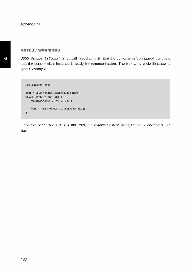
480
Appendix G
G
NOTES / WARNINGS
USBD_Vendor_IsConn() is typically used to verify that the device is in ‘configured’ state and
that the vendor class instance is ready for communication. The following code illustrates a
typical example:
Once the connected status is DEF_YES, the communication using the Bulk endpoints can
start.
CPU_BOOLEAN conn;
conn = USBD_Vendor_IsConn(class_nbr);
while (conn != DEF_YES) {
OSTimeDlyHMSM(0, 0, 0, 250);
conn = USBD_Vendor_IsConn(class_nbr);
}
481
G
G-1-5 USBD_Vendor_Rd()
Receive data from host through Bulk OUT endpoint. This function is blocking.
FILES
usbd_vendor.c
PROTOTYPE
ARGUMENTS
class_nbr Class instance number.
p_buf Pointer to receive buffer.
buf_len Receive buffer length in octets.
timeout Timeout in milliseconds.
p_err Pointer to variable that will receive the return error code from this function.
USBD_ERR_NONE
USBD_ERR_NULL_PTR
USBD_ERR_INVALID_ARG
USBD_ERR_INVALID_CLASS_STATE
USBD_ERR_DEV_INVALID_NBR
USBD_ERR_EP_INVALID_NBR
USBD_ERR_DEV_INVALID_STATE
USBD_ERR_EP_INVALID_TYPE
CPU_INT32U USBD_Vendor_Rd (CPU_INT08U class_nbr,
void *p_buf,
CPU_INT32U buf_len,
CPU_INT16U timeout,
USBD_ERR *p_err);

482
Appendix G
G
RETURNED VALUE
Number of octets received, if NO error(s).
0, otherwise.
CALLERS
Application.
NOTES / WARNINGS
None.
483
G
G-1-6 USBD_Vendor_Wr()
Send data to host through Bulk IN endpoint. This function is blocking.
FILES
usbd_vendor.c
PROTOTYPE
ARGUMENTS
class_nbr Class instance number.
p_buf Pointer to transmit buffer.
buf_len Transmit buffer length in octets.
timeout Timeout in milliseconds.
end End-of-transfer flag.
p_err Pointer to variable that will receive the return error code from this function.
USBD_ERR_NONE
USBD_ERR_NULL_PTR
USBD_ERR_INVALID_ARG
USBD_ERR_INVALID_CLASS_STATE
USBD_ERR_DEV_INVALID_NBR
USBD_ERR_EP_INVALID_NBR
USBD_ERR_DEV_INVALID_STATE
USBD_ERR_EP_INVALID_TYPE
CPU_INT32U USBD_Vendor_Wr (CPU_INT08U class_nbr,
void *p_buf,
CPU_INT32U buf_len,
CPU_INT16U timeout,
CPU_BOOLEAN end,
USBD_ERR *p_err);

484
Appendix G
G
RETURNED VALUE
Number of octets sent, if NO error(s).
0, otherwise.
CALLERS
Application.
NOTES / WARNINGS
If end-of-transfer flag is set and transfer length is multiple of maximum packet size, a zero-
length packet is transferred to indicate the end of transfer to the host.

485
G
G-1-7 USBD_Vendor_RdAsync()
Receive data from host through Bulk OUT endpoint. This function is non-blocking. It
returns immediately after transfer preparation. Upon transfer completion, a callback
provided by the application will be called to finalize the transfer.
FILES
usbd_vendor.c
PROTOTYPE
ARGUMENTS
class_nbr Class instance number.
p_buf Pointer to receive buffer.
buf_len Receive buffer length in octets.
async_fnct Receive callback.
p_async_arg Additional argument provided by application for receive callback.
p_err Pointer to variable that will receive the return error code from this function.
USBD_ERR_NONE
USBD_ERR_NULL_PTR
USBD_ERR_INVALID_ARG
USBD_ERR_INVALID_CLASS_STATE
USBD_ERR_DEV_INVALID_NBR
USBD_ERR_EP_INVALID_NBR
void USBD_Vendor_RdAsync (CPU_INT08U class_nbr,
void *p_buf,
CPU_INT32U buf_len,
USBD_VENDOR_ASYNC_FNCT async_fnct,
void *p_async_arg,
USBD_ERR *p_err);
486
Appendix G
G
USBD_ERR_DEV_INVALID_STATE
USBD_ERR_EP_INVALID_TYPE
USBD_ERR_EP_INVALID_STATE
RETURNED VALUE
None.
CALLERS
Application.
NOTES / WARNINGS
None.
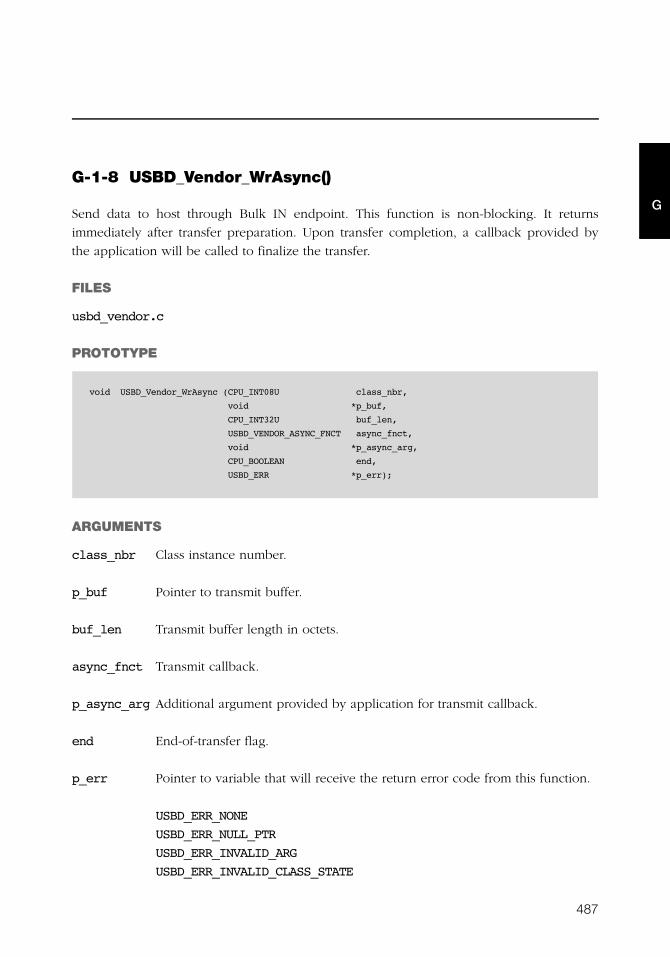
487
G
G-1-8 USBD_Vendor_WrAsync()
Send data to host through Bulk IN endpoint. This function is non-blocking. It returns
immediately after transfer preparation. Upon transfer completion, a callback provided by
the application will be called to finalize the transfer.
FILES
usbd_vendor.c
PROTOTYPE
ARGUMENTS
class_nbr Class instance number.
p_buf Pointer to transmit buffer.
buf_len Transmit buffer length in octets.
async_fnct Transmit callback.
p_async_arg Additional argument provided by application for transmit callback.
end End-of-transfer flag.
p_err Pointer to variable that will receive the return error code from this function.
USBD_ERR_NONE
USBD_ERR_NULL_PTR
USBD_ERR_INVALID_ARG
USBD_ERR_INVALID_CLASS_STATE
void USBD_Vendor_WrAsync (CPU_INT08U class_nbr,
void *p_buf,
CPU_INT32U buf_len,
USBD_VENDOR_ASYNC_FNCT async_fnct,
void *p_async_arg,
CPU_BOOLEAN end,
USBD_ERR *p_err);
488
Appendix G
G
USBD_ERR_DEV_INVALID_NBR
USBD_ERR_EP_INVALID_NBR
USBD_ERR_DEV_INVALID_STATE
USBD_ERR_EP_INVALID_TYPE
USBD_ERR_EP_INVALID_STATE
RETURNED VALUE
Number of octets sent, if NO error(s).
0, otherwise.
CALLERS
Application.
NOTES / WARNINGS
If end-of-transfer flag is set and transfer length is multiple of maximum packet size, a zero-
length packet is transferred to indicate the end of transfer to the host.

489
G
G-1-9 USBD_Vendor_IntrRd()
Receive data from host through Interrupt OUT endpoint. This function is blocking.
FILES
usbd_vendor.c
PROTOTYPE
ARGUMENTS
class_nbr Class instance number.
p_buf Pointer to receive buffer.
buf_len Receive buffer length in octets.
timeout Timeout in milliseconds.
p_err Pointer to variable that will receive the return error code from this function.
USBD_ERR_NONE
USBD_ERR_NULL_PTR
USBD_ERR_INVALID_ARG
USBD_ERR_INVALID_CLASS_STATE
USBD_ERR_DEV_INVALID_NBR
USBD_ERR_EP_INVALID_NBR
USBD_ERR_DEV_INVALID_STATE
USBD_ERR_EP_INVALID_TYPE
CPU_INT32U USBD_Vendor_IntrRd (CPU_INT08U class_nbr,
void *p_buf,
CPU_INT32U buf_len,
CPU_INT16U timeout,
USBD_ERR *p_err);

490
Appendix G
G
RETURNED VALUE
Number of octets received, if NO error(s).
0, otherwise.
CALLERS
Application.
NOTES / WARNINGS
None.
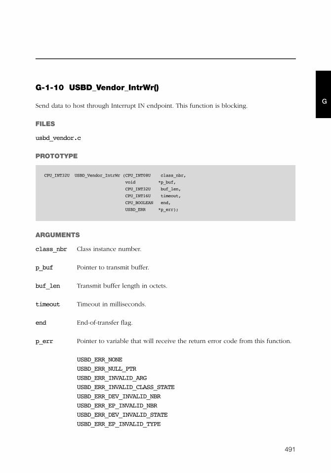
491
G
G-1-10 USBD_Vendor_IntrWr()
Send data to host through Interrupt IN endpoint. This function is blocking.
FILES
usbd_vendor.c
PROTOTYPE
ARGUMENTS
class_nbr Class instance number.
p_buf Pointer to transmit buffer.
buf_len Transmit buffer length in octets.
timeout Timeout in milliseconds.
end End-of-transfer flag.
p_err Pointer to variable that will receive the return error code from this function.
USBD_ERR_NONE
USBD_ERR_NULL_PTR
USBD_ERR_INVALID_ARG
USBD_ERR_INVALID_CLASS_STATE
USBD_ERR_DEV_INVALID_NBR
USBD_ERR_EP_INVALID_NBR
USBD_ERR_DEV_INVALID_STATE
USBD_ERR_EP_INVALID_TYPE
CPU_INT32U USBD_Vendor_IntrWr (CPU_INT08U class_nbr,
void *p_buf,
CPU_INT32U buf_len,
CPU_INT16U timeout,
CPU_BOOLEAN end,
USBD_ERR *p_err);
492
Appendix G
G
RETURNED VALUE
Number of octets sent, if NO error(s).
0, otherwise.
CALLERS
Application.
NOTES / WARNINGS
If end-of-transfer flag is set and transfer length is multiple of maximum packet size, a zero-
length packet is transferred to indicate the end of transfer to the host.
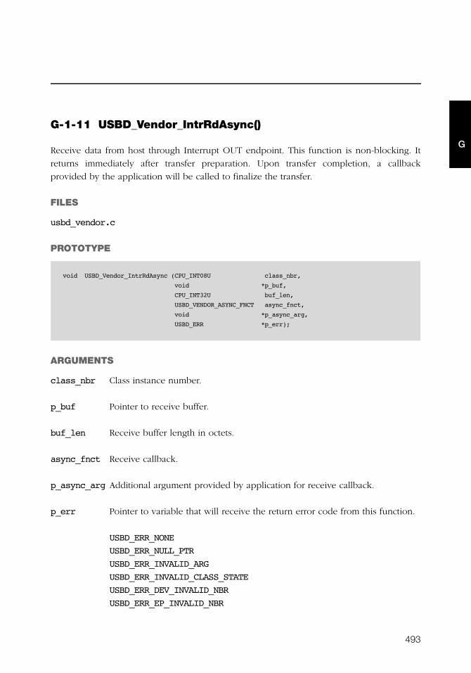
493
G
G-1-11 USBD_Vendor_IntrRdAsync()
Receive data from host through Interrupt OUT endpoint. This function is non-blocking. It
returns immediately after transfer preparation. Upon transfer completion, a callback
provided by the application will be called to finalize the transfer.
FILES
usbd_vendor.c
PROTOTYPE
ARGUMENTS
class_nbr Class instance number.
p_buf Pointer to receive buffer.
buf_len Receive buffer length in octets.
async_fnct Receive callback.
p_async_arg Additional argument provided by application for receive callback.
p_err Pointer to variable that will receive the return error code from this function.
USBD_ERR_NONE
USBD_ERR_NULL_PTR
USBD_ERR_INVALID_ARG
USBD_ERR_INVALID_CLASS_STATE
USBD_ERR_DEV_INVALID_NBR
USBD_ERR_EP_INVALID_NBR
void USBD_Vendor_IntrRdAsync (CPU_INT08U class_nbr,
void *p_buf,
CPU_INT32U buf_len,
USBD_VENDOR_ASYNC_FNCT async_fnct,
void *p_async_arg,
USBD_ERR *p_err);

494
Appendix G
G
USBD_ERR_DEV_INVALID_STATE
USBD_ERR_EP_INVALID_TYPE
USBD_ERR_EP_INVALID_STATE
RETURNED VALUE
None.
CALLERS
Application.
NOTES / WARNINGS
None.

495
G
G-1-12 USBD_Vendor_IntrWrAsync()
Send data to host through Interrupt IN endpoint. This function is non-blocking. It returns
immediately after transfer preparation. Upon transfer completion, a callback provided by
the application will be called to finalize the transfer.
FILES
usbd_vendor.c
PROTOTYPE
ARGUMENTS
class_nbr Class instance number.
p_buf Pointer to transmit buffer.
buf_len Transmit buffer length in octets.
async_fnct Transmit callback.
p_async_arg Additional argument provided by application for transmit callback.
end End-of-transfer flag.
p_err Pointer to variable that will receive the return error code from this function.
USBD_ERR_NONE
USBD_ERR_NULL_PTR
USBD_ERR_INVALID_ARG
USBD_ERR_INVALID_CLASS_STATE
void USBD_Vendor_IntrWrAsync (CPU_INT08U class_nbr,
void *p_buf,
CPU_INT32U buf_len,
USBD_VENDOR_ASYNC_FNCT async_fnct,
void *p_async_arg,
CPU_BOOLEAN end,
USBD_ERR *p_err);

496
Appendix G
G
USBD_ERR_DEV_INVALID_NBR
USBD_ERR_EP_INVALID_NBR
USBD_ERR_DEV_INVALID_STATE
USBD_ERR_EP_INVALID_TYPE
USBD_ERR_EP_INVALID_STATE
RETURNED VALUE
Number of octets sent, if NO error(s).
0, otherwise.
CALLERS
Application.
NOTES / WARNINGS
If end-of-transfer flag is set and transfer length is multiple of maximum packet size, a zero-
length packet is transferred to indicate the end of transfer to the host.
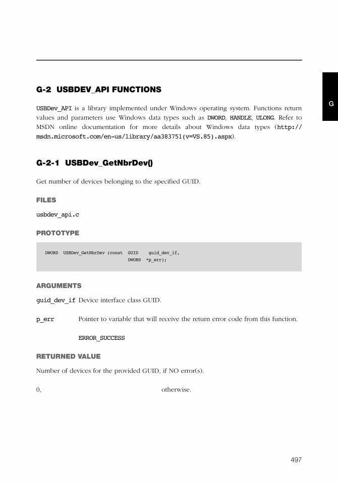
497
G
G-2 USBDEV_API FUNCTIONS
USBDev_API is a library implemented under Windows operating system. Functions return
values and parameters use Windows data types such as DWORD, HANDLE, ULONG. Refer to
MSDN online documentation for more details about Windows data types (http://
msdn.microsoft.com/en-us/library/aa383751(v=VS.85).aspx).
G-2-1 USBDev_GetNbrDev()
Get number of devices belonging to the specified GUID.
FILES
usbdev_api.c
PROTOTYPE
ARGUMENTS
guid_dev_if Device interface class GUID.
p_err Pointer to variable that will receive the return error code from this function.
ERROR_SUCCESS
RETURNED VALUE
Number of devices for the provided GUID, if NO error(s).
0, otherwise.
DWORD USBDev_GetNbrDev (const GUID guid_dev_if,
DWORD *p_err);
498
Appendix G
G
CALLERS
Application.
NOTES / WARNINGS
The function USBDev_GetNbrDev() uses the concept of device information set. A device
information set consists of device information elements for all the devices that belong to
some device setup class or device interface class. The GUID passed to
USBDev_GetNbrDev() function is a device interface class. Internally by using some control
options the function retrieves the device information set which represents a list of all
devices present in the system and registered under the specified GUID. More details about
the device information set can be found at http://msdn.microsoft.com/en-us/
library/ff541247(VS.85).aspx.
499
G
G-2-2 USBDev_Open()
Open a device by retrieving a general device handle.
FILES
usbdev_api.c
PROTOTYPE
ARGUMENTS
guid_dev_if Device interface class GUID.
dev_nbr Device number.
p_err Pointer to variable that will receive the return error code from this function:
ERROR_SUCCESS
ERROR_INVALID_PARAMETER
ERROR_NOT_ENOUGH_MEMORY
ERROR_BAD_DEVICE
RETURNED VALUE
Handle to device, if NO error(s).
INVALID_HANDLE_VALUE, otherwise.
CALLERS
Application.
NOTES / WARNINGS
None.
HANDLE USBDev_Open (const GUID guid_dev_if,
DWORD dev_nbr,
DWORD *p_err);
500
Appendix G
G
G-2-3 USBDev_Close()
Close a device by freeing any allocated resources and by releasing any created handles.
FILES
usbdev_api.c
PROTOTYPE
ARGUMENTS
dev General handle to device.
p_err Pointer to variable that will receive the return error code from this function:
ERROR_SUCCESS
ERROR_INVALID_HANDLE
RETURNED VALUE
None.
CALLERS
Application.
NOTES / WARNINGS
USBDev_Close() closes any remaining open pipes. The open pipes are usually closed from
the application by calling the function USBDev_PipeClose().
void USBDev_Close (HANDLE dev,
DWORD *p_err);
501
G
G-2-4 USBDev_GetNbrAltSetting()
Get number of alternate settings for the specified interface.
FILES
usbdev_api.c
PROTOTYPE
ARGUMENTS
dev General handle to device.
if_nbr Interface number.
p_err Pointer to variable that will receive the return error code from this function:
ERROR_SUCCESS
ERROR_INVALID_HANDLE
ERROR_INVALID_PARAMETER
RETURNED VALUE
Number of alternate setting, if NO error(s).
0, otherwise.
CALLERS
Application.
UCHAR USBDev_GetNbrAltSetting (HANDLE dev,
UCHAR if_nbr,
DWORD *p_err);
502
Appendix G
G
NOTES / WARNINGS
An interface may include alternate settings that allow the endpoints and/or their
characteristics to be varied after the device has been configured. The default setting for an
interface is always alternate setting zero. Alternate settings allow a portion of the device
configuration to be varied while other interfaces remain in operation.
The number of alternate settings gotten can be used to open a pipe associated with a
certain alternate interface.
503
G
G-2-5 USBDev_GetNbrAssociatedIF()
Get number of associated interfaces with the default interface. That is all the interfaces
besides the default interface managed by WinUSB.sys and registered under the same GUID.
FILES
usbdev_api.c
PROTOTYPE
ARGUMENTS
dev General handle to device.
p_err Pointer to variable that will receive the return error code from this function:
ERROR_SUCCESS
ERROR_INVALID_HANDLE
RETURNED VALUE
Number of associated interfaces, if NO error(s).
0, otherwise.
CALLERS
Application.
NOTES / WARNINGS
Let’s assume that a device has three interfaces managed by WinUSB.sys driver and
belonging to the same GUID: Interface #0, #1 and #2. Interface #0 is the default interface.
Interfaces #1 and #2 are the associated interfaces. In that example calling
USBDev_GetNbrAssociatedIF() will return 2 associated interfaces.
UCHAR USBDev_GetNbrAssociatedIF (HANDLE dev,
DWORD *p_err);
504
Appendix G
G
G-2-6 USBDev_SetAltSetting()
Set the alternate setting of an interface.
FILES
usbdev_api.c
PROTOTYPE
ARGUMENTS
dev General handle to device.
if_nbr Interface number.
alt_set Alternate setting number.
p_err Pointer to variable that will receive the return error code from this function:
ERROR_SUCCESS
ERROR_INVALID_HANDLE
ERROR_INVALID_PARAMETER
RETURNED VALUE
None.
CALLERS
Application.
void USBDev_SetAltSetting (HANDLE dev,
UCHAR if_nbr,
UCHAR alt_set,
DWORD *p_err);

505
G
NOTES / WARNINGS
This function sets alternate setting number for WinUSB internal use. It does not send a
SET_INTERFACE request to the device. To send SET_INTERFACE request to the device, the
function USBDev_CtrlReq() must be used.
506
Appendix G
G
G-2-7 USBDev_GetCurAltSetting()
Get the current alternate setting for the specified interface.
FILES
usbdev_api.c
PROTOTYPE
ARGUMENTS
dev General handle to device.
if_nbr Interface number.
p_err Pointer to variable that will receive the return error code from this function:
ERROR_SUCCESS
ERROR_INVALID_HANDLE
ERROR_INVALID_PARAMETER
RETURNED VALUE
Current alternate setting number, if NO error(s).
0, otherwise.
CALLERS
Application.
UCHAR USBDev_GetCurAltSetting (HANDLE dev,
UCHAR if_nbr,
DWORD *p_err);

507
G
NOTES / WARNINGS
This function gets the current alternate setting number used internally by WinUSB and set
by the function USBDev_SetAltSetting(). It does NOT send a GET_INTERFACE request to
the device. To send GET_INTERFACE request to the device, the function USBDev_CtrlReq()
must be used.
508
Appendix G
G
G-2-8 USBDev_IsHighSpeed()
Specify if the device attached to PC is high speed or not.
FILES
usbdev_api.c
PROTOTYPE
ARGUMENTS
dev General handle to device.
p_err Pointer to variable that will receive the return error code from this function:
ERROR_SUCCESS
ERROR_INVALID_HANDLE
ERROR_INVALID_PARAMETER
RETURNED VALUE
TRUE, if device is high-speed.
FALSE, otherwise.
CALLERS
Application.
NOTES / WARNINGS
None.
BOOL USBDev_IsHighSpeed (HANDLE dev,
DWORD *p_err);

509
G
G-2-9 USBDev_BulkIn_Open()
Open a Bulk IN pipe.
FILES
usbdev_api.c
PROTOTYPE
ARGUMENTS
dev General handle to device.
if_nbr Interface number.
alt_set Alternate setting number for specified interface.
p_err Pointer to variable that will receive the return error code from this function:
ERROR_SUCCESS
ERROR_INVALID_HANDLE
ERROR_NO_MORE_ITEMS
RETURNED VALUE
Handle to Bulk IN pipe, if NO error(s).
INVALID_HANDLE_VALUE, otherwise.
CALLERS
Application.
NOTES / WARNINGS
None.
HANDLE USBDev_BulkIn_Open (HANDLE dev,
UCHAR if_nbr,
UCHAR alt_set,
DWORD *p_err);
510
Appendix G
G
G-2-10 USBDev_BulkOut_Open()
Open a Bulk OUT pipe.
FILES
usbdev_api.c
PROTOTYPE
ARGUMENTS
dev General handle to device.
if_nbr Interface number.
alt_set Alternate setting number for specified interface.
p_err Pointer to variable that will receive the return error code from this function:
ERROR_SUCCESS
ERROR_INVALID_HANDLE
ERROR_NO_MORE_ITEMS
RETURNED VALUE
Handle to Bulk OUT pipe, if NO error(s).
INVALID_HANDLE_VALUE, otherwise.
CALLERS
Application.
NOTES / WARNINGS
None.
HANDLE USBDev_BulkOut_Open (HANDLE dev,
UCHAR if_nbr,
UCHAR alt_set,
DWORD *p_err);
511
G
G-2-11 USBDev_IntrIn_Open()
Open a Interrupt IN pipe.
FILES
usbdev_api.c
PROTOTYPE
ARGUMENTS
dev General handle to device.
if_nbr Interface number.
alt_set Alternate setting number for specified interface.
p_err Pointer to variable that will receive the return error code from this function:
ERROR_SUCCESS
ERROR_INVALID_HANDLE
ERROR_NO_MORE_ITEMS
RETURNED VALUE
Handle to Interrupt IN pipe, if NO error(s).
INVALID_HANDLE_VALUE, otherwise.
CALLERS
Application.
NOTES / WARNINGS
None.
HANDLE USBDev_IntrIn_Open (HANDLE dev,
UCHAR if_nbr,
UCHAR alt_set,
DWORD *p_err);
512
Appendix G
G
G-2-12 USBDev_IntrOut_Open()
Open a Interrupt OUT pipe.
FILES
usbdev_api.c
PROTOTYPE
ARGUMENTS
dev General handle to device.
if_nbr Interface number.
alt_set Alternate setting number for specified interface.
p_err Pointer to variable that will receive the return error code from this function:
ERROR_SUCCESS
ERROR_INVALID_HANDLE
ERROR_NO_MORE_ITEMS
RETURNED VALUE
Handle to Interrupt OUT pipe, if NO error(s).
INVALID_HANDLE_VALUE, otherwise.
CALLERS
Application.
NOTES / WARNINGS
None.
HANDLE USBDev_IntrOut_Open (HANDLE dev,
UCHAR if_nbr,
UCHAR alt_set,
DWORD *p_err);
513
G
G-2-13 USBDev_PipeGetAddr()
Get pipe address.
FILES
usbdev_api.c
PROTOTYPE
ARGUMENTS
pipe Pipe handle.
p_err Pointer to variable that will receive the return error code from this function:
ERROR_SUCCESS
ERROR_INVALID_HANDLE
RETURNED VALUE
Pipe address, if NO error(s).
0, otherwise.
CALLERS
Application.
NOTES / WARNINGS
None.
UCHAR USBDev_PipeGetAddr (HANDLE pipe,
DWORD *p_err);
514
Appendix G
G
G-2-14 USBDev_PipeClose()
Close a pipe.
FILES
usbdev_api.c
PROTOTYPE
ARGUMENTS
pipe Pipe handle.
p_err Pointer to variable that will receive the return error code from this function:
ERROR_SUCCESS
ERROR_INVALID_HANDLE
RETURNED VALUE
None
CALLERS
Application.
NOTES / WARNINGS
None.
void USBDev_PipeClose (HANDLE pipe,
DWORD *p_err);
515
G
G-2-15 USBDev_PipeStall()
Stall a pipe or clear the stall condition of a pipe.
FILES
usbdev_api.c
PROTOTYPE
ARGUMENTS
pipe Pipe handle.
stall Indicate which action to do:
TRUE Stall pipe.
FALSE Clear stall condition of the pipe.
p_err Pointer to variable that will receive the return error code from this function:
ERROR_SUCCESS
ERROR_INVALID_HANDLE
ERROR_NOT_ENOUGH_MEMORY
RETURNED VALUE
None.
CALLERS
Application.
NOTES / WARNINGS
The SET_FEATURE standard request is sent to the device to stall the pipe. The CLEAR_FEATURE
standard request is sent to the device to clear the stall condition of the pipe.
void USBDev_PipeStall (HANDLE pipe,
BOOL stall,
DWORD *p_err);

516
Appendix G
G
G-2-16 USBDev_PipeAbort()
Aborts all of the pending transfers for a pipe.
FILES
usbdev_api.c
PROTOTYPE
ARGUMENTS
pipe Pipe handle.
p_err Pointer to variable that will receive the return error code from this function:
ERROR_SUCCESS
ERROR_INVALID_HANDLE
RETURNED VALUE
None.
CALLERS
Application.
NOTES / WARNINGS
None.
void USBDev_PipeAbort (HANDLE pipe,
DWORD *p_err);
517
G
G-2-17 USBDev_CtrlReq()
Send control data over the default control endpoint.
FILES
usbdev_api.c
PROTOTYPE
ARGUMENTS
dev General handle to device
bm_req_type Variable representing bmRequestType of setup packet. bmRequestType is a
bitmap with the following characteristics:
D7 Data transfer direction:
‘0’: USB_DIR_HOST_TO_DEVICE
‘1’: USB_DIR_DEVICE_TO_HOST
D6...5 Request type:
‘00’: USB_REQUEST_TYPE_STD (standard)
‘01’: USB_REQUEST_TYPE_CLASS
‘10’: USB_REQUEST_TYPE_VENDOR
ULONG USBDev_CtrlReq (HANDLE dev,
UCHAR bm_req_type,
UCHAR b_request,
USHORT w_value,
USHORT w_index,
UCHAR *p_buf,
USHORT buf_len,
DWORD *p_err);
518
Appendix G
G
D4...0 Recipient:
‘0000’: USB_RECIPIENT_DEV (device)
‘0001’: USB_RECIPIENT_IF (interface)
‘0010’: USB_RECIPIENT_ENDPOINT
bm_req_type Argument is a OR'ed of D7, D6...5 and
D4...0 values.
b_request Variable representing bRequest of setup packet. Possible values are:
GET_STATUS Returns status for the specified recipient.
CLEAR_FEATURE Clear or disable a specific feature.
SET_FEATURE Set or enable a specific feature.
SET_ADDRESS Set the device address for all future
device accesses.
GET_DESCRIPTOR Return the specified descriptor if the
descriptor exists.
SET_DESCRIPTOR Update existing descriptors or new
descriptors may be added.
GET_CONFIGURATION Return the current device configuration
value.
SET_CONFIGURATION Set the device configuration.
GET_INTERFACE Return the selected alternate setting for
the specified interface.
SET_INTERFACE Select an alternate setting for the
specified interface.
SYNCH_FRAME Set and then report an endpoint’s
synchronization frame.
w_value Variable representing wValue of setup packet.
w_index Variable representing wIndex of setup packet.
p_buf Pointer to transmit or receive buffer for data phase of control transfer.
buf_len Length of transmit or receive buffer.
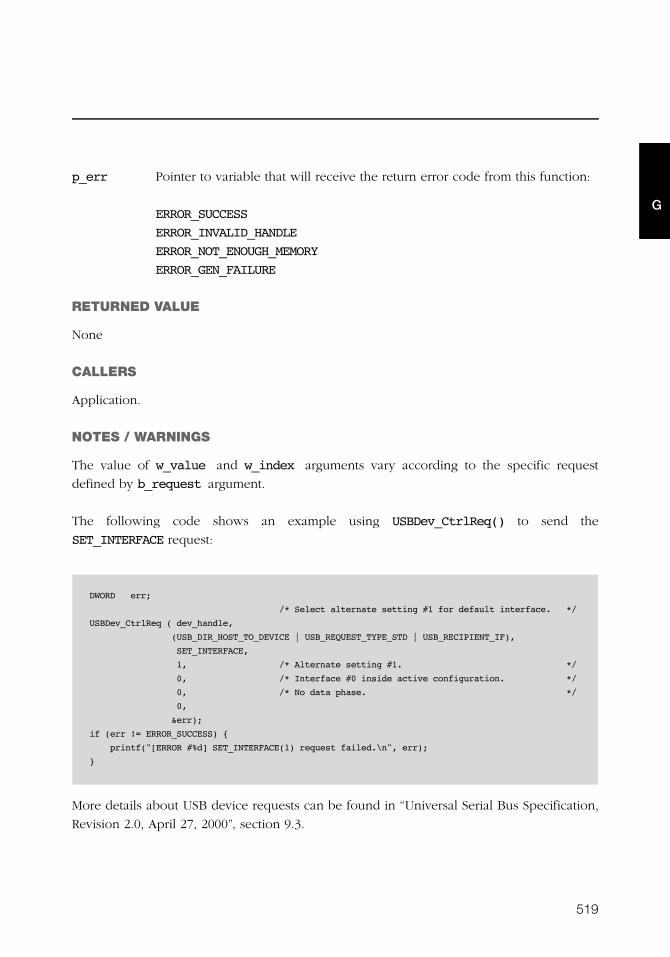
519
G
p_err Pointer to variable that will receive the return error code from this function:
ERROR_SUCCESS
ERROR_INVALID_HANDLE
ERROR_NOT_ENOUGH_MEMORY
ERROR_GEN_FAILURE
RETURNED VALUE
None
CALLERS
Application.
NOTES / WARNINGS
The value of w_value and w_index arguments vary according to the specific request
defined by b_request argument.
The following code shows an example using USBDev_CtrlReq() to send the
SET_INTERFACE request:
More details about USB device requests can be found in “Universal Serial Bus Specification,
Revision 2.0, April 27, 2000”, section 9.3.
DWORD err;
/* Select alternate setting #1 for default interface. */
USBDev_CtrlReq ( dev_handle,
(USB_DIR_HOST_TO_DEVICE | USB_REQUEST_TYPE_STD | USB_RECIPIENT_IF),
SET_INTERFACE,
1, /* Alternate setting #1. */
0, /* Interface #0 inside active configuration. */
0, /* No data phase. */
0,
&err);
if (err != ERROR_SUCCESS) {
printf("[ERROR #%d] SET_INTERFACE(1) request failed.\n", err);
}

520
Appendix G
G
G-2-18 USBDev_PipeWr()
Write data to device over the specified pipe.
FILES
usbdev_api.c
PROTOTYPE
ARGUMENTS
pipe Pipe handle.
p_buf Pointer to transmit buffer.
buf_len Transmit buffer length.
timeout Timeout in milliseconds. A value of 0 indicates a wait forever.
p_err Pointer to variable that will receive the return error code from this function:
ERROR_SUCCESS
ERROR_INVALID_HANDLE
ERROR_INVALID_USER_BUFFER
ERROR_BAD_PIPE
ERROR_INVALID_PARAMETER
ERROR_NOT_ENOUGH_MEMORY
ERROR_SEM_TIMEOUT
DWORD USBDev_PipeWr (HANDLE pipe,
UCHAR *p_buf,
DWORD buf_len,
DWORD timeout,
DWORD *p_err);
521
G
RETURNED VALUE
Number of bytes written, if NO error(s).
0, otherwise.
CALLERS
Application.
NOTES / WARNINGS
None.
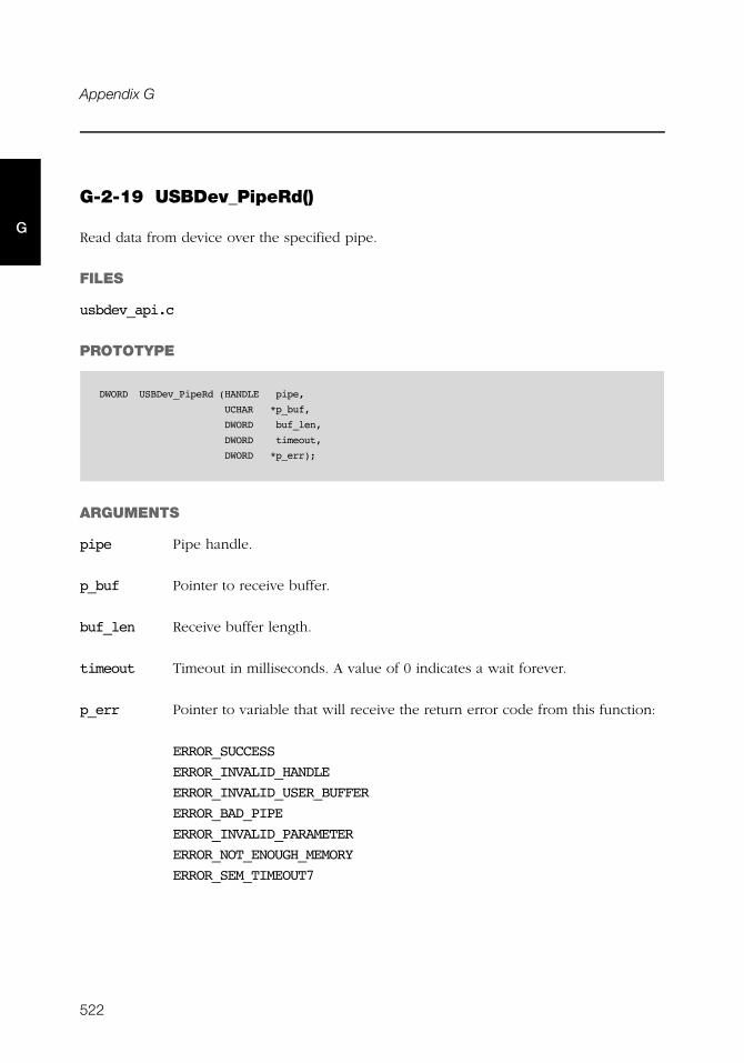
522
Appendix G
G
G-2-19 USBDev_PipeRd()
Read data from device over the specified pipe.
FILES
usbdev_api.c
PROTOTYPE
ARGUMENTS
pipe Pipe handle.
p_buf Pointer to receive buffer.
buf_len Receive buffer length.
timeout Timeout in milliseconds. A value of 0 indicates a wait forever.
p_err Pointer to variable that will receive the return error code from this function:
ERROR_SUCCESS
ERROR_INVALID_HANDLE
ERROR_INVALID_USER_BUFFER
ERROR_BAD_PIPE
ERROR_INVALID_PARAMETER
ERROR_NOT_ENOUGH_MEMORY
ERROR_SEM_TIMEOUT7
DWORD USBDev_PipeRd (HANDLE pipe,
UCHAR *p_buf,
DWORD buf_len,
DWORD timeout,
DWORD *p_err);

523
G
RETURNED VALUE
Number of bytes received, if NO error(s).
0, otherwise.
CALLERS
Application.
NOTES / WARNINGS
None.
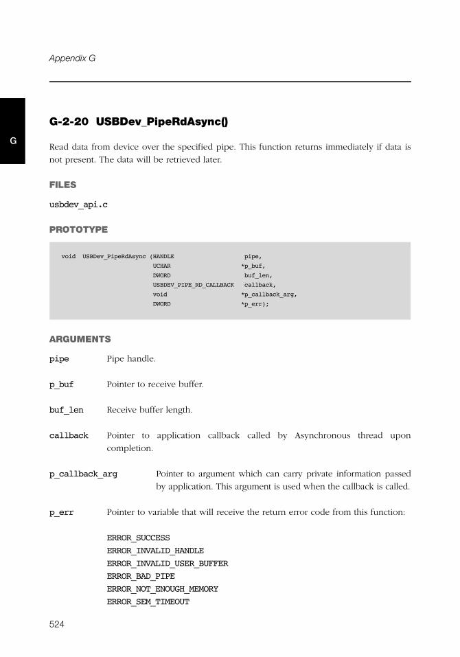
524
Appendix G
G
G-2-20 USBDev_PipeRdAsync()
Read data from device over the specified pipe. This function returns immediately if data is
not present. The data will be retrieved later.
FILES
usbdev_api.c
PROTOTYPE
ARGUMENTS
pipe Pipe handle.
p_buf Pointer to receive buffer.
buf_len Receive buffer length.
callback Pointer to application callback called by Asynchronous thread upon
completion.
p_callback_arg Pointer to argument which can carry private information passed
by application. This argument is used when the callback is called.
p_err Pointer to variable that will receive the return error code from this function:
ERROR_SUCCESS
ERROR_INVALID_HANDLE
ERROR_INVALID_USER_BUFFER
ERROR_BAD_PIPE
ERROR_NOT_ENOUGH_MEMORY
ERROR_SEM_TIMEOUT
void USBDev_PipeRdAsync (HANDLE pipe,
UCHAR *p_buf,
DWORD buf_len,
USBDEV_PIPE_RD_CALLBACK callback,
void *p_callback_arg,
DWORD *p_err);
525
G
RETURNED VALUE
None.
CALLERS
Application.
NOTES / WARNINGS
When a IN pipe is open with one of the open functions USBDev_xxxxIn_Open(), a thread
is automatically created. This thread is in charge of informing the application about a
completed asynchronous IN transfer. Upon completion of an asynchronous transfer, the
thread is waken up and calls the application callback provided to USBDev_API library using
the callback argument.
USBDev_API library allows to queue several asynchronous IN transfers for the same pipe.

526
Appendix G
G

527
Appendix
HError Codes
This appendix provides a brief explanation of μC/USB-Device error codes defined in
usbd_core.h. Any error codes not listed here may be searched in usbd_core.h for both
their numerical value and usage.
Each error has a numerical value. The error codes are grouped. The definition of the
groups are:
Error code group Numbering series
GENERIC 0
DEVICE 100
CONFIGURATION 200
INTERFACE 300
ENDPOINT 400
OS LAYER 500
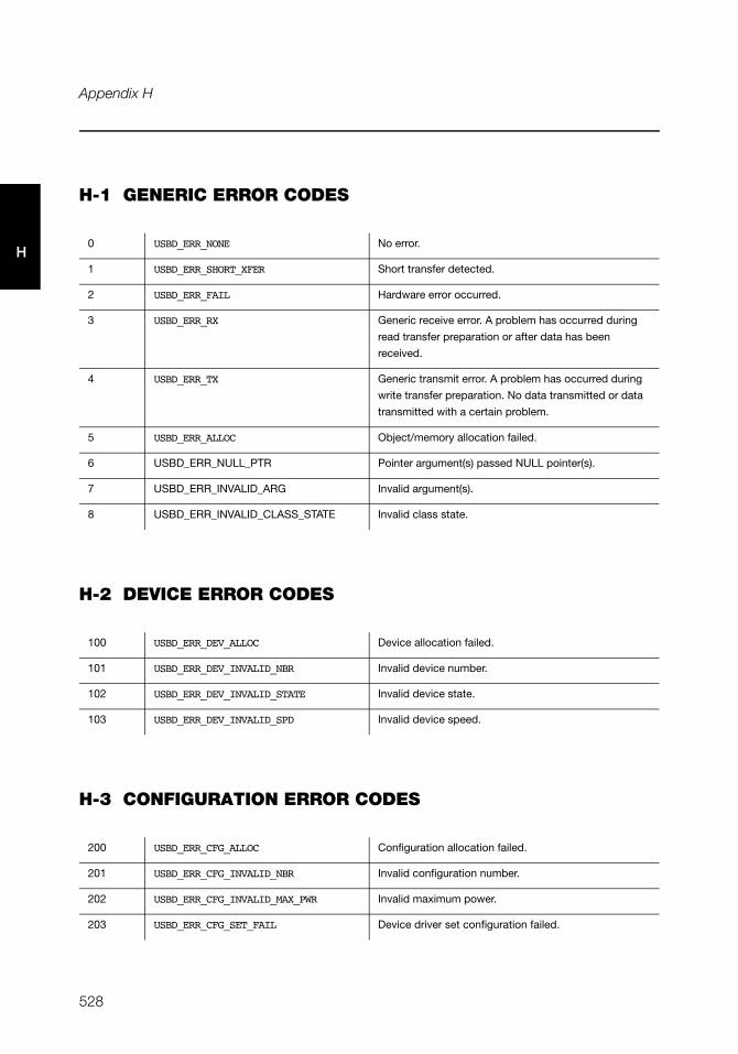
528
Appendix H
H
H-1 GENERIC ERROR CODES
H-2 DEVICE ERROR CODES
H-3 CONFIGURATION ERROR CODES
0 USBD_ERR_NONE No error.
1 USBD_ERR_SHORT_XFER Short transfer detected.
2 USBD_ERR_FAIL Hardware error occurred.
3 USBD_ERR_RX Generic receive error. A problem has occurred during
read transfer preparation or after data has been
received.
4 USBD_ERR_TX Generic transmit error. A problem has occurred during
write transfer preparation. No data transmitted or data
transmitted with a certain problem.
5 USBD_ERR_ALLOC Object/memory allocation failed.
6 USBD_ERR_NULL_PTR Pointer argument(s) passed NULL pointer(s).
7 USBD_ERR_INVALID_ARG Invalid argument(s).
8 USBD_ERR_INVALID_CLASS_STATE Invalid class state.
100 USBD_ERR_DEV_ALLOC Device allocation failed.
101 USBD_ERR_DEV_INVALID_NBR Invalid device number.
102 USBD_ERR_DEV_INVALID_STATE Invalid device state.
103 USBD_ERR_DEV_INVALID_SPD Invalid device speed.
200 USBD_ERR_CFG_ALLOC Configuration allocation failed.
201 USBD_ERR_CFG_INVALID_NBR Invalid configuration number.
202 USBD_ERR_CFG_INVALID_MAX_PWR Invalid maximum power.
203 USBD_ERR_CFG_SET_FAIL Device driver set configuration failed.
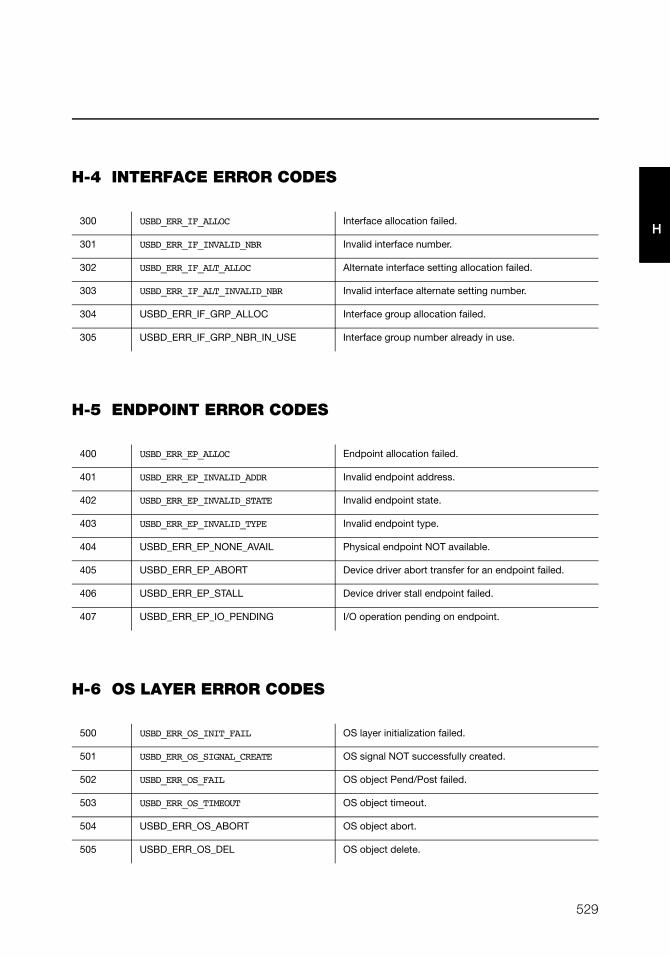
529
H
H-4 INTERFACE ERROR CODES
H-5 ENDPOINT ERROR CODES
H-6 OS LAYER ERROR CODES
300 USBD_ERR_IF_ALLOC Interface allocation failed.
301 USBD_ERR_IF_INVALID_NBR Invalid interface number.
302 USBD_ERR_IF_ALT_ALLOC Alternate interface setting allocation failed.
303 USBD_ERR_IF_ALT_INVALID_NBR Invalid interface alternate setting number.
304 USBD_ERR_IF_GRP_ALLOC Interface group allocation failed.
305 USBD_ERR_IF_GRP_NBR_IN_USE Interface group number already in use.
400 USBD_ERR_EP_ALLOC Endpoint allocation failed.
401 USBD_ERR_EP_INVALID_ADDR Invalid endpoint address.
402 USBD_ERR_EP_INVALID_STATE Invalid endpoint state.
403 USBD_ERR_EP_INVALID_TYPE Invalid endpoint type.
404 USBD_ERR_EP_NONE_AVAIL Physical endpoint NOT available.
405 USBD_ERR_EP_ABORT Device driver abort transfer for an endpoint failed.
406 USBD_ERR_EP_STALL Device driver stall endpoint failed.
407 USBD_ERR_EP_IO_PENDING I/O operation pending on endpoint.
500 USBD_ERR_OS_INIT_FAIL OS layer initialization failed.
501 USBD_ERR_OS_SIGNAL_CREATE OS signal NOT successfully created.
502 USBD_ERR_OS_FAIL OS object Pend/Post failed.
503 USBD_ERR_OS_TIMEOUT OS object timeout.
504 USBD_ERR_OS_ABORT OS object abort.
505 USBD_ERR_OS_DEL OS object delete.

530
Appendix H
H
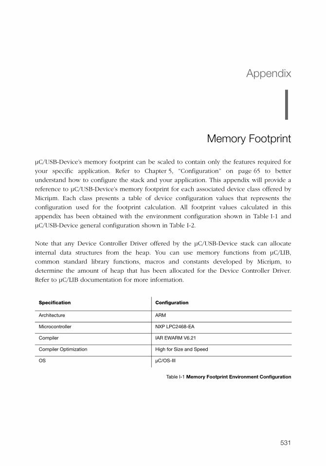
531
Appendix
IMemory Footprint
μC/USB-Device’s memory footprint can be scaled to contain only the features required for
your specific application. Refer to Chapter 5, “Configuration” on page 65 to better
understand how to configure the stack and your application. This appendix will provide a
reference to μC/USB-Device’s memory footprint for each associated device class offered by
Micriμm. Each class presents a table of device configuration values that represents the
configuration used for the footprint calculation. All footprint values calculated in this
appendix has been obtained with the environment configuration shown in Table I-1 and
μC/USB-Device general configuration shown in Table I-2.
Note that any Device Controller Driver offered by the μC/USB-Device stack can allocate
internal data structures from the heap. You can use memory functions from μC/LIB,
common standard library functions, macros and constants developed by Micriμm, to
determine the amount of heap that has been allocated for the Device Controller Driver.
Refer to μC/LIB documentation for more information.
Table I-1 Memory Footprint Environment Configuration
Specification Configuration
Architecture ARM
Microcontroller NXP LPC2468-EA
Compiler IAR EWARM V6.21
Compiler Optimization High for Size and Speed
OS μC/OS-III
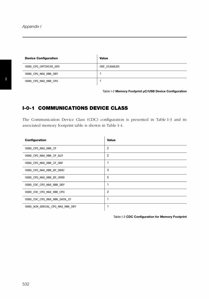
532
Appendix I
I
Table I-2 Memory Footprint μC/USB Device Configuration
I-0-1 COMMUNICATIONS DEVICE CLASS
The Communication Device Class (CDC) configuration is presented in Table I-3 and its
associated memory footprint table is shown in Table I-4.
Table I-3 CDC Configuration for Memory Footprint
Device Configuration Value
USBD_CFG_OPTIMIZE_SPD DEF_DISABLED
USBD_CFG_MAX_NBR_DEV 1
USBD_CFG_MAX_NBR_CFG 1
Configuration Value
USBD_CFG_MAX_NBR_IF 2
USBD_CFG_MAX_NBR_IF_ALT 2
USBD_CFG_MAX_NBR_IF_GRP 1
USBD_CFG_MAX_NBR_EP_DESC 3
USBD_CFG_MAX_NBR_EP_OPEN 5
USBD_CDC_CFG_MAX_NBR_DEV 1
USBD_CDC_CFG_MAX_NBR_CFG 2
USBD_CDC_CFG_MAX_NBR_DATA_IF 1
USBD_ACM_SERIAL_CFG_MAX_NBR_DEV 1
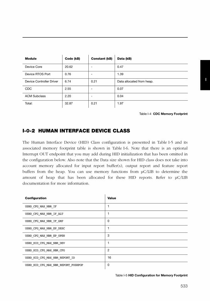
533
I
Table I-4 CDC Memory Footprint
I-0-2 HUMAN INTERFACE DEVICE CLASS
The Human Interface Device (HID) Class configuration is presented in Table I-5 and its
associated memory footprint table is shown in Table I-6. Note that there is an optional
Interrupt OUT endpoint that you may add during HID initialization that has been omitted in
the configuration below. Also note that the Data size shown for HID class does not take into
account memory allocated for input report buffer(s), output report and feature report
buffers from the heap. You can use memory functions from μC/LIB to determine the
amount of heap that has been allocated for these HID reports. Refer to μC/LIB
documentation for more information.
Table I-5 HID Configuration for Memory Footprint
Module Code (kB) Constant (kB) Data (kB)
Device Core 20.62 - 0.47
Device RTOS Port 0.76 - 1.39
Device Controller Driver 6.74 0.21 Data allocated from heap.
CDC 2.55 - 0.07
ACM Subclass 2.20 - 0.04
Total: 32.87 0.21 1.97
Configuration Value
USBD_CFG_MAX_NBR_IF 1
USBD_CFG_MAX_NBR_IF_ALT 1
USBD_CFG_MAX_NBR_IF_GRP 0
USBD_CFG_MAX_NBR_EP_DESC 1
USBD_CFG_MAX_NBR_EP_OPEN 3
USBD_HID_CFG_MAX_NBR_DEV 1
USBD_HID_CFG_MAX_NBR_CFG 2
USBD_HID_CFG_MAX_NBR_REPORT_ID 16
USBD_HID_CFG_MAX_NBR_REPORT_PUSHPOP 0

534
Appendix I
I
Table I-6 HID Memory Footprint
I-0-3 MASS STORAGE CLASS
The Mass Storage Class (MSC) configuration is presented in Table I-7 and its associated
memory footprint table is shown in Table I-8.
Table I-7 MSC Configuration for Memory Footprint
Module Code (kB) Constant (kB) Data (kB)
Device Core 19.17 - 0.78
Device RTOS Port 0.76 - 1.31
Device Controller
Driver
6.74 0.21 *Data allocated from heap.
HID 6.29 - 0.52
*Input, Output and/or Feature Report buffers allocated
from heap. Refer to section I-0-2 “Human Interface
Device Class” on page 533 for details.
HID RTOS Port 1.05 - 1.39
Total: 34.01 0.21 4.00
Configuration Value
USBD_CFG_MAX_NBR_IF 1
USBD_CFG_MAX_NBR_IF_ALT 1
USBD_CFG_MAX_NBR_IF_GRP 0
USBD_CFG_MAX_NBR_EP_DESC 2
USBD_CFG_MAX_NBR_EP_OPEN 4
USBD_MSC_CFG_MAX_NBR_DEV 1
USBD_MSC_CFG_MAX_NBR_CFG 2
USBD_MSC_CFG_MAX_LUN 1
USBD_MSC_CFG_DATA_LEN 2048
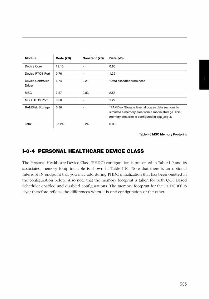
535
I
Table I-8 MSC Memory Footprint
I-0-4 PERSONAL HEALTHCARE DEVICE CLASS
The Personal Healthcare Device Class (PHDC) configuration is presented in Table I-9 and its
associated memory footprint table is shown in Table I-10. Note that there is an optional
Interrupt IN endpoint that you may add during PHDC initialization that has been omitted in
the configuration below. Also note that the memory footprint is taken for both QOS Based
Scheduler enabled and disabled configurations. The memory footprint for the PHDC RTOS
layer therefore reflects the differences when it is one configuration or the other.
Module Code (kB) Constant (kB) Data (kB)
Device Core 19.13 - 0.85
Device RTOS Port 0.76 - 1.35
Device Controller
Driver
6.74 0.21 *Data allocated from heap.
MSC 7.57 0.03 2.55
MSC RTOS Port 0.68 - 1.27
RAMDisk Storage 0.36 - *RAMDisk Storage layer allocates data sections to
simulate a memory area from a media storage. This
memory area size is configured in app_cfg.h.
Total: 35.24 0.24 6.02
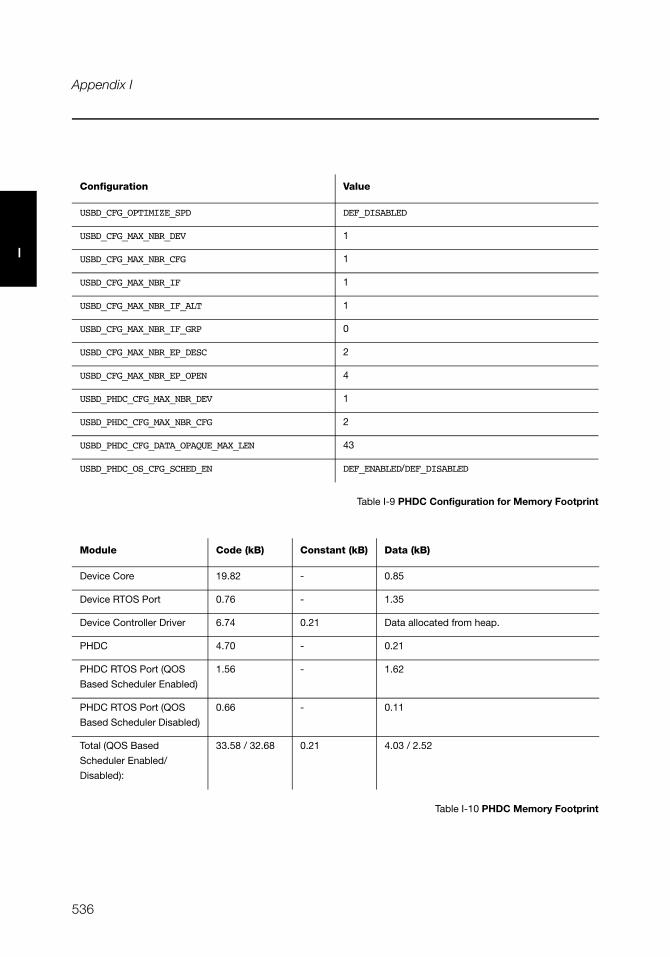
536
Appendix I
I
Table I-9 PHDC Configuration for Memory Footprint
Table I-10 PHDC Memory Footprint
Configuration Value
USBD_CFG_OPTIMIZE_SPD DEF_DISABLED
USBD_CFG_MAX_NBR_DEV 1
USBD_CFG_MAX_NBR_CFG 1
USBD_CFG_MAX_NBR_IF 1
USBD_CFG_MAX_NBR_IF_ALT 1
USBD_CFG_MAX_NBR_IF_GRP 0
USBD_CFG_MAX_NBR_EP_DESC 2
USBD_CFG_MAX_NBR_EP_OPEN 4
USBD_PHDC_CFG_MAX_NBR_DEV 1
USBD_PHDC_CFG_MAX_NBR_CFG 2
USBD_PHDC_CFG_DATA_OPAQUE_MAX_LEN 43
USBD_PHDC_OS_CFG_SCHED_EN DEF_ENABLED/DEF_DISABLED
Module Code (kB) Constant (kB) Data (kB)
Device Core 19.82 - 0.85
Device RTOS Port 0.76 - 1.35
Device Controller Driver 6.74 0.21 Data allocated from heap.
PHDC 4.70 - 0.21
PHDC RTOS Port (QOS
Based Scheduler Enabled)
1.56 - 1.62
PHDC RTOS Port (QOS
Based Scheduler Disabled)
0.66 - 0.11
Total (QOS Based
Scheduler Enabled/
Disabled):
33.58 / 32.68 0.21 4.03 / 2.52
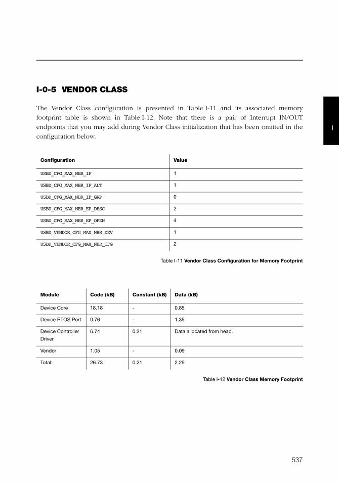
537
I
I-0-5 VENDOR CLASS
The Vendor Class configuration is presented in Table I-11 and its associated memory
footprint table is shown in Table I-12. Note that there is a pair of Interrupt IN/OUT
endpoints that you may add during Vendor Class initialization that has been omitted in the
configuration below.
Table I-11 Vendor Class Configuration for Memory Footprint
Table I-12 Vendor Class Memory Footprint
Configuration Value
USBD_CFG_MAX_NBR_IF 1
USBD_CFG_MAX_NBR_IF_ALT 1
USBD_CFG_MAX_NBR_IF_GRP 0
USBD_CFG_MAX_NBR_EP_DESC 2
USBD_CFG_MAX_NBR_EP_OPEN 4
USBD_VENDOR_CFG_MAX_NBR_DEV 1
USBD_VENDOR_CFG_MAX_NBR_CFG 2
Module Code (kB) Constant (kB) Data (kB)
Device Core 18.18 - 0.85
Device RTOS Port 0.76 - 1.35
Device Controller
Driver
6.74 0.21 Data allocated from heap.
Vendor 1.05 - 0.09
Total: 26.73 0.21 2.29

538
Appendix I
I
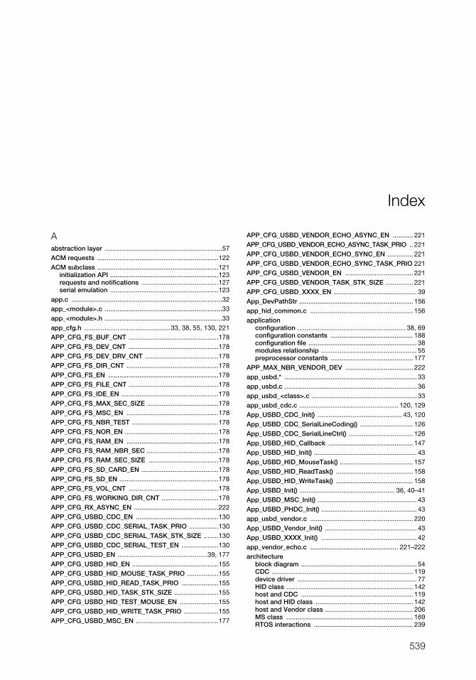
539
Index
Aabstraction layer ................................................................57ACM requests ..................................................................122ACM subclass ..................................................................121
initialization API ...........................................................123requests and notifications ..........................................127serial emulation ...........................................................123
app.c ..................................................................................32app_<module>.c ................................................................33app_<module>.h ................................................................33app_cfg.h ...............................................33, 38, 55, 130, 221APP_CFG_FS_BUF_CNT .................................................178APP_CFG_FS_DEV_CNT .................................................178APP_CFG_FS_DEV_DRV_CNT ........................................178APP_CFG_FS_DIR_CNT ..................................................178APP_CFG_FS_EN ............................................................178APP_CFG_FS_FILE_CNT .................................................178APP_CFG_FS_IDE_EN .....................................................178APP_CFG_FS_MAX_SEC_SIZE .......................................178APP_CFG_FS_MSC_EN ..................................................178APP_CFG_FS_NBR_TEST ...............................................178APP_CFG_FS_NOR_EN ...................................................178APP_CFG_FS_RAM_EN ..................................................178APP_CFG_FS_RAM_NBR_SEC .......................................178APP_CFG_FS_RAM_SEC_SIZE ......................................178APP_CFG_FS_SD_CARD_EN ..........................................178APP_CFG_FS_SD_EN ......................................................178APP_CFG_FS_VOL_CNT .................................................178APP_CFG_FS_WORKING_DIR_CNT ...............................178APP_CFG_RX_ASYNC_EN ..............................................222APP_CFG_USBD_CDC_EN .............................................130APP_CFG_USBD_CDC_SERIAL_TASK_PRIO ................130APP_CFG_USBD_CDC_SERIAL_TASK_STK_SIZE ........130APP_CFG_USBD_CDC_SERIAL_TEST_EN ....................130APP_CFG_USBD_EN .................................................39, 177APP_CFG_USBD_HID_EN ...............................................155APP_CFG_USBD_HID_MOUSE_TASK_PRIO .................155APP_CFG_USBD_HID_READ_TASK_PRIO ....................155APP_CFG_USBD_HID_TASK_STK_SIZE ........................155APP_CFG_USBD_HID_TEST_MOUSE_EN .....................155APP_CFG_USBD_HID_WRITE_TASK_PRIO ...................155APP_CFG_USBD_MSC_EN .............................................177
APP_CFG_USBD_VENDOR_ECHO_ASYNC_EN ........... 221APP_CFG_USBD_VENDOR_ECHO_ASYNC_TASK_PRIO .. 221APP_CFG_USBD_VENDOR_ECHO_SYNC_EN .............. 221APP_CFG_USBD_VENDOR_ECHO_SYNC_TASK_PRIO 221APP_CFG_USBD_VENDOR_EN ..................................... 221APP_CFG_USBD_VENDOR_TASK_STK_SIZE ............... 221APP_CFG_USBD_XXXX_EN ............................................. 39App_DevPathStr .............................................................. 156app_hid_common.c ........................................................ 156application
configuration ........................................................... 38, 69configuration constants ............................................. 188configuration file ........................................................... 38modules relationship .................................................... 55preprocessor constants ............................................. 177
APP_MAX_NBR_VENDOR_DEV ..................................... 222app_usbd.* ........................................................................ 33app_usbd.c ........................................................................ 36app_usbd_<class>.c ......................................................... 33app_usbd_cdc.c ...................................................... 120, 129App_USBD_CDC_Init() .............................................. 43, 120App_USBD_CDC_SerialLineCoding() ............................. 126App_USBD_CDC_SerialLineCtrl() ................................... 126App_USBD_HID_Callback .............................................. 147App_USBD_HID_Init() ........................................................ 43App_USBD_HID_MouseTask() ........................................ 157App_USBD_HID_ReadTask() .......................................... 158App_USBD_HID_WriteTask() .......................................... 158App_USBD_Init() .................................................... 36, 40–41App_USBD_MSC_Init() ...................................................... 43App_USBD_PHDC_Init() .................................................... 43app_usbd_vendor.c ........................................................ 220App_USBD_Vendor_Init() .................................................. 43App_USBD_XXXX_Init() .................................................... 42app_vendor_echo.c ................................................ 221–222architecture
block diagram ............................................................... 54CDC ............................................................................. 119device driver ................................................................. 77HID class ..................................................................... 142host and CDC ............................................................. 119host and HID class ..................................................... 142host and Vendor class ................................................ 206MS class ..................................................................... 169RTOS interactions ...................................................... 239
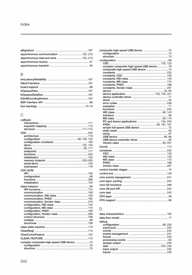
540
Index
aSignature ........................................................................187asynchronous communication ................................152, 212asynchronous read and write .................................153, 213asynchronous receive .......................................................91asynchronous transmit ......................................................95
BbmLatencyReliability .......................................................187bNumTransfers ................................................................187board support ....................................................................88bOpaqueData ...................................................................187bOpaqueDataSize ............................................................187bQoSEncodingVersion ....................................................187BSP interface API ..............................................................88bus topology ................................................................15–16
Ccallback
interactions ..................................................................111requests mapping .......................................................113structure ..............................................................111–112
CDC ..................................................................................532architecture .................................................................119configuration .................................................68, 120, 123configuration constants ..............................................120demo ....................................................................132, 134device ....................................................................50, 117endpoints ....................................................................117functions ......................................................................354initialization .................................................................120memory footprint ................................................532–533serial demo ..................................................................133subclasses ..................................................................118
CDC-ACMAPI ...............................................................................128configuration .................................................................68functions ......................................................................369initialization .................................................................125
class instance ....................................................................99API functions ...............................................................174communication ...........................................................109communication, HID class ..........................................150communication, PHDC ...............................................192communication, Vendor class ....................................210configuration, HID class .............................................144configuration, MS class ..............................................174configuration, PHDC ...................................................189configuration, Vendor class ........................................208control structure .........................................................108multiple ..........................................................................99structures ....................................................................108
class state machine .........................................................110ClassReq() ........................................................................113ClearCommFeature .........................................................122CLEAR_FEATURE ............................................................113complex composite high-speed USB device ...................74
configuration .................................................................76structure ........................................................................75
composite high-speed USB device ................................. 73configuration ................................................................. 74structure ........................................................................ 73
configuration ..................................................................... 66CDC ..................................................................... 120, 123complex composite high-speed USB device .............. 76composite high-speed USB device ............................. 74constants .................................................................... 232constants, CDC .......................................................... 120constants, HID class .................................................. 143constants, MS class ................................................... 173constants, PHDC ........................................................ 188constants, Vendor class ............................................. 207device ...................................................................... 34, 85device application ...................................... 130, 155, 221device controller driver ................................................ 71driver ............................................................................. 35error codes ................................................................. 528examples ....................................................................... 71functions ..................................................................... 253HID class ............................................................... 68, 143interface ........................................................................ 66MS class ............................................................... 69, 173PC and device applications ............................... 154, 220PHDC ............................................................ 69, 187, 191simple full-speed USB device ...................................... 72static stack ................................................................... 65string ............................................................................. 67USB device ............................................................. 66, 86USB device controller driver ........................................ 85Vendor class ......................................................... 69, 207
Conn() .............................................................................. 113constants ......................................................................... 232
CDC ............................................................................. 120HID class ..................................................................... 143MS class ..................................................................... 173PHDC .......................................................................... 188Vendor class ............................................................... 207
control transfer stages ...................................................... 19control.exe ....................................................................... 159core events management ............................................... 241core layer, porting ........................................................... 242core OS functions ........................................................... 298core OS port API ............................................................. 242core task .......................................................................... 243CPU layer ........................................................................... 58CPU support ...................................................................... 88
Ddata characteristics ........................................................ 184data flow model ................................................................. 17debug
configuration ......................................................... 68, 232event pool ................................................................... 234events .......................................................................... 234events management ................................................... 241format .......................................................................... 233processing events ........................................................ 63sample output ............................................................. 233task ...................................................................... 234, 243trace output ................................................................ 232traces .......................................................................... 232
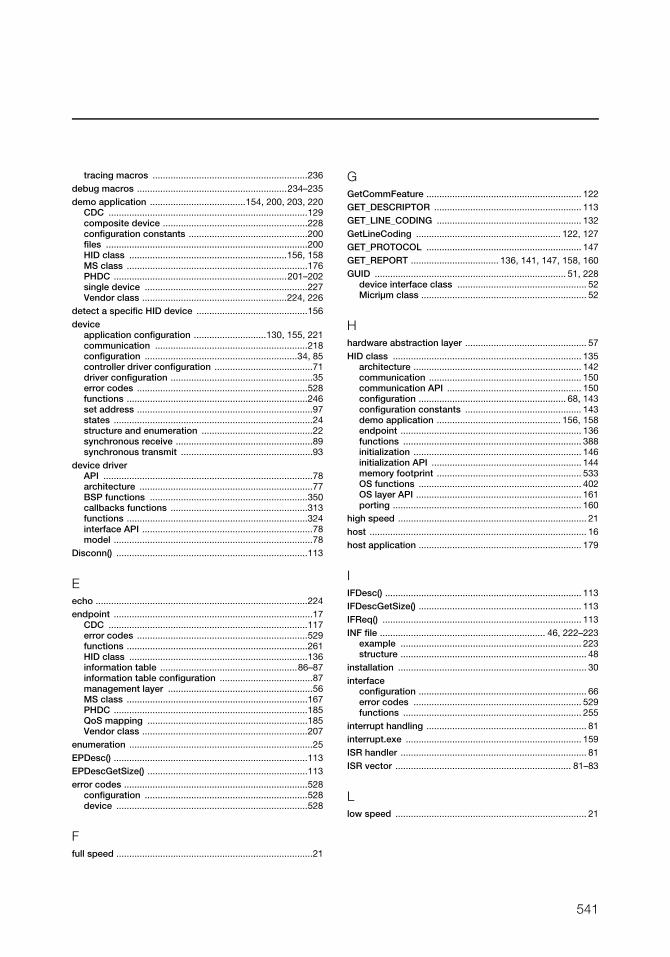
541
tracing macros ............................................................236debug macros ..........................................................234–235demo application .....................................154, 200, 203, 220
CDC .............................................................................129composite device ........................................................228configuration constants ..............................................200files ..............................................................................200HID class .............................................................156, 158MS class ......................................................................176PHDC ...................................................................201–202single device ...............................................................227Vendor class ........................................................224, 226
detect a specific HID device ...........................................156device
application configuration ............................130, 155, 221communication ...........................................................218configuration ...........................................................34, 85controller driver configuration ......................................71driver configuration .......................................................35error codes ..................................................................528functions ......................................................................246set address ....................................................................97states .............................................................................24structure and enumeration ...........................................22synchronous receive .....................................................89synchronous transmit ...................................................93
device driverAPI .................................................................................78architecture ...................................................................77BSP functions .............................................................350callbacks functions .....................................................313functions ......................................................................324interface API ..................................................................78model .............................................................................78
Disconn() ..........................................................................113
Eecho ..................................................................................224endpoint .............................................................................17
CDC .............................................................................117error codes ..................................................................529functions ......................................................................261HID class .....................................................................136information table .....................................................86–87information table configuration ....................................87management layer ........................................................56MS class ......................................................................167PHDC ...........................................................................185QoS mapping ..............................................................185Vendor class ................................................................207
enumeration .......................................................................25EPDesc() ...........................................................................113EPDescGetSize() ..............................................................113error codes .......................................................................528
configuration ...............................................................528device ..........................................................................528
Ffull speed ............................................................................21
GGetCommFeature ............................................................ 122GET_DESCRIPTOR ......................................................... 113GET_LINE_CODING ........................................................ 132GetLineCoding ........................................................ 122, 127GET_PROTOCOL ............................................................ 147GET_REPORT .................................. 136, 141, 147, 158, 160GUID .......................................................................... 51, 228
device interface class .................................................. 52Micriμm class ................................................................ 52
Hhardware abstraction layer ............................................... 57HID class ......................................................................... 135
architecture ................................................................. 142communication ........................................................... 150communication API .................................................... 150configuration ......................................................... 68, 143configuration constants ............................................. 143demo application ................................................ 156, 158endpoint ...................................................................... 136functions ..................................................................... 388initialization ................................................................. 146initialization API .......................................................... 144memory footprint ........................................................ 533OS functions ............................................................... 402OS layer API ................................................................ 161porting ......................................................................... 160
high speed ......................................................................... 21host .................................................................................... 16host application ............................................................... 179
IIFDesc() ............................................................................ 113IFDescGetSize() ............................................................... 113IFReq() ............................................................................. 113INF file ................................................................ 46, 222–223
example ...................................................................... 223structure ........................................................................ 48
installation ......................................................................... 30interface
configuration ................................................................. 66error codes ................................................................. 529functions ..................................................................... 255
interrupt handling .............................................................. 81interrupt.exe .................................................................... 159ISR handler ........................................................................ 81ISR vector .................................................................... 81–83
Llow speed .......................................................................... 21
542
Index
Mmemory allocation .............................................................88memory footprint .............................................................531
CDC .....................................................................532–533HID class .....................................................................533MS class ......................................................................534PHDC ...................................................................535–536Vendor class ................................................................537
metadata preamble .........................................187, 192, 196module
dependency ..................................................................29libraries ..........................................................................55relationship ....................................................................55
mouse demo ....................................................................156Mouse Report Descriptor Example ................................148MS class ...........................................................................534
architecture .................................................................169configuration .........................................................69, 173configuration constants ..............................................173demo application ........................................................176endpoint ......................................................................167endpoint usage ...........................................................167functions ......................................................................420initialization .................................................................176memory footprint ........................................................534OS functions ................................................................428porting .................................................................180–181protocol .......................................................................166requests .......................................................................167state machine ..............................................................172storage layer functions ...............................................434task handler .................................................................171
multiple class instances ............................ 99–103, 106–107
Nnotification API ..................................................................84
OOS layer API .....................................................................204OS layer error codes ........................................................529
Pperiodic input reports task ......................................161–162PHDC ........................................................................184, 535
communication ...........................................................192communication API .....................................................192configuration .................................................69, 187, 191configuration constants ..............................................188data characteristics ....................................................184demo application ................................................201–202endpoint ......................................................................185functions ......................................................................442initialization API ...........................................................189instance initialization ..................................................191memory footprint ................................................535–536operational model .......................................................185OS layer functions .......................................................463porting .........................................................................203read ..............................................................................193software layers ............................................................186
write ............................................................................ 195physical interface .............................................................. 21pipe management ........................................................... 215pipes .................................................................................. 18porting
core layer .................................................................... 242HID class ..................................................................... 160modules ...................................................................... 239MS class ............................................................. 180–181PHDC .......................................................................... 203
power distribution ............................................................. 22power management .......................................................... 21preprocessor constants .................................................. 178processing USB requests ........................................... 61–62
QQoS
bins .............................................................................. 190endpoint mapping ...................................................... 186levels description ....................................................... 185
QoS-based schedule .............................................. 196, 199QoS-based scheduler API .............................................. 198
RRAM disk ......................................................................... 177receive ......................................................................... 59–60
asynchronous ............................................................... 91synchronous ................................................................. 89
report ............................................................................... 136descriptor content ...................................................... 139items ........................................................................... 138mouse state ................................................................ 141
RTOSAPI functions .............................................................. 181layer ............................................................................. 171model .......................................................................... 240port .............................................................................. 238QoS-based scheduler ................................................ 196
Ssample application ............................................................ 40
building ......................................................................... 31SCSI ................................................................................. 168SCSI commands ............................................................. 170SemaphorePost() ............................................................ 238serial demo .............................................................. 132–134
state machine ............................................................. 133serial read and write ....................................................... 128serial terminal .................................................................. 134SetBreak .......................................................................... 122SetCommFeature ............................................................ 122SET_CONFIGURATION ........................................... 110, 113SET_CONTROL_LINE_STATE ........................................ 132SetControlLineState ................................................ 122, 127SET_FEATURE ................................................................ 113SET_IDLE ................................................................. 161–162
543
SET_INTERFACE .............................................................113SET_LINE_CODING .........................................................132SetLineCoding .........................................................122, 127SET_PROTOCOL .............................................................147SET_REPORT ...................................................136, 147, 158simple full-speed USB device ...........................................72
configuration .................................................................72source code .......................................................................37
downloading ..................................................................28including ........................................................................37
speed .................................................................................21state machine ..................................................................172static stack configuration ..................................................65status notification API .......................................................84storage API ......................................................................181storage layer ....................................................................171
functions ......................................................................434storage medium ...............................................................171string configuration ...........................................................67subclass
management ...............................................................127notification ...................................................................127
subclass instancecommunication ...........................................................128configuration ...............................................................123
synchronous bulk read and write ...........................151, 211synchronous communication ..................................150, 211synchronous transfer completion ...................................240
Ttask
execution order ...........................................................197model .......................................................................58–59priorities .........................................................................69
task stack sizes .................................................................70TaskCreate() .....................................................................238template files .....................................................................33trace functions .................................................................321transfer types .....................................................................18transmit ........................................................................59–60
asynchronous ................................................................95synchronous ..................................................................93
UuC/FS preprocessor constants .......................................178UpdateAltSetting() ...........................................................113UpdateEPState() ..............................................................113USB
class layer .....................................................................56core layer .......................................................................56data flow ........................................................................20device ............................................................................16device application .......................................................177device configuration .....................................................66device configuration structure .....................................86device controller driver configuration ..........................85device driver data type .................................................80
device driver functional model .................................... 89device states ................................................................ 25device structure ...................................................... 22, 24host ............................................................................... 16host application .......................................................... 179
USBD_ACM_SerialAdd() ................. 123–124, 126, 129, 370USBD_ACM_SerialCfgAdd() ................... 123–124, 126, 371USBD_ACM_SERIAL_CFG_MAX_NBR_DEV ........... 76, 123USBD_ACM_SerialInit() ................................... 123–124, 369USBD_ACM_SerialIsConn() ............................................ 373USBD_ACM_SerialLineCodingGet() ....................... 127, 381USBD_ACM_SerialLineCodingReg() ...... 123–124, 127, 383USBD_ACM_SerialLineCodingSet() ....................... 127, 382USBD_ACM_SerialLineCtrlGet() ............................. 127, 378USBD_ACM_SerialLineCtrlReg() ............ 123–124, 127, 379USBD_ACM_SerialLineStateClr() ............................ 127, 386USBD_ACM_SerialLineStateSet() ........................... 127, 385USBD_ACM_SerialRx() ............................................ 128, 374USBD_ACM_SerialTx() ............................................ 128, 376usbd_bsp_<controller>.c .................................................. 58USBD_BSP_Conn() ......................................................... 351USBD_BSP_Disconn() ..................................................... 352USBD_BSP_Init() ............................................................. 350USBD_BulkAdd() ............................................................. 265USBD_BulkRx() ................................................... 89–90, 267USBD_BulkRxAsync() ............................................... 91, 269USBD_BulkTx() .......................................................... 93, 271USBD_BulkTxAsync() ................................................ 95, 273USBD_CDC_Add() ........................................................... 355USBD_CDC_CfgAdd() ..................................................... 358USBD_CDC_CFG_MAX_NBR_CFG .......................... 76, 120USBD_CDC_CFG_MAX_NBR_DATA_IF ......................... 120USBD_CDC_CFG_MAX_NBR_DEV .................. 76, 120, 123USBD_CDC_DataIF_Add() .............................................. 361USBD_CDC_DataRx() ..................................................... 363USBD_CDC_DataTx() ...................................................... 365USBD_CDC_Init() ............................................................. 354USBD_CDC_IsConn() ...................................................... 360USBD_CDC_Notify() ........................................................ 367usbd_cfg.c ......................................................................... 34usbd_cfg.h ................... 34, 55, 120, 123, 143, 187, 207, 232USBD_CfgAdd() ............................................................... 253USBD_CFG_DBG_TRACE_EN .................................. 68, 232USBD_CFG_DBG_TRACE_NBR_EVENTS ....... 68, 232, 234USBD_CFG_MAX_NBR_CFG ......................... 66, 72, 74, 76USBD_CFG_MAX_NBR_DEV ............................................ 66USBD_CFG_MAX_NBR_EP_DESC ................. 67, 72, 74, 76USBD_CFG_MAX_NBR_EP_OPEN ................ 67, 72, 74, 76USBD_CFG_MAX_NBR_IF .............................. 66, 72, 74, 76USBD_CFG_MAX_NBR_IF_ALT ..................... 67, 72, 74, 76USBD_CFG_MAX_NBR_IF_GRP .................... 67, 72, 74, 76USBD_CFG_MAX_NBR_STR ............................................ 67USBD_CFG_OPTIMIZE_SPD ............................................ 66USBD_CfgOtherSpeed() ................................................. 104USBD_CLASS_DRV ........................................................ 111
544
Index
usbd_core.c .....................................................................235usbd_core.h .....................................................................234USBD_CoreTaskHandler() .......................................242, 300USBD_CtrlRx() .....................................................89–90, 263USBD_CtrlTx() ............................................................93, 261USBD_Dbg() .....................................................................234USBD_DbgArg() ...............................................................234USBD_DbgTaskHandler() ........................................243, 301USBD_DevAdd() .........................................................42, 251USBD_DEV_CFG ........................................................85, 156usbd_dev_cfg.c .......................................34–35, 55, 85, 156usbd_dev_cfg.h .....................................................34, 55, 85USBD_DevGetState() .......................................................249USBD_DEV_SPD_FULL .....................................................85USBD_DEV_SPD_HIGH .....................................................85USBD_DEV_SPD_LOW ......................................................85USBD_DevStart() .............................................................247USBD_DevStop() ..............................................................248USBD_DrvAddrEn() ....................................................97, 330USBD_DrvAddrSet() ...................................................97, 329USBD_DRV_CFG ...............................................................85USBD_DrvCfgClr() ............................................................332USBD_DrvCfgSet() ...........................................................331USBD_DrvEP_Abort() ......................................................347USBD_DrvEP_Close() ......................................................336USBD_DrvEP_Open() .......................................................334USBD_DrvEP_Rx() ...............................................90, 92, 339USBD_DrvEP_RxStart() .......................................90–92, 337USBD_DrvEP_RxZLP() ....................................................341USBD_DrvEP_Stall() ........................................................348USBD_DrvEP_Tx() ..........................................93, 95–96, 342USBD_DrvEP_TxStart() ........................................94, 96, 344USBD_DrvEP_TxZLP() .....................................................346USBD_DrvGetFrameNbr() ................................................333USBD_DrvInit() .................................................................324USBD_DrvISR_Handler() .....................................81, 83, 349USBD_DrvStart() ..............................................................326USBD_DrvStop() ..............................................................328USBD_EP_Abort() ............................................................291USBD_EP_GetMaxNbrOpen() .........................................297USBD_EP_GetMaxPhyNbr() ............................................296USBD_EP_GetMaxPktSize() ............................................295USBD_EP_INFO_DIR .........................................................87USBD_EP_INFO_DIR_IN ....................................................87USBD_EP_INFO_DIR_OUT ................................................87USBD_EP_INFO_TYPE ......................................................87USBD_EP_INFO_TYPE_BULK ...........................................87USBD_EP_INFO_TYPE_CTRL ...........................................87USBD_EP_INFO_TYPE_INTR ............................................87USBD_EP_INFO_TYPE_ISOC ............................................87USBD_EP_IsStalled() .......................................................294USBD_EP_Process() ..........................................................92USBD_EP_Rx() .............................................................90–91USBD_EP_RxCmpl() ......................................84, 90, 92, 313
USBD_EP_RxZLP() .......................................................... 287USBD_EP_Stall() .............................................................. 292USBD_EP_Tx() ....................................................... 93, 95–96USBD_EP_TxCmpl() ...................................... 84, 94, 96, 314USBD_EP_TxZLP() .......................................................... 289USBDev_API .................................................................... 214USBDev_API and WinUSB .............................................. 215USBDev_API Asynchronous Read Example .................. 219USBDev_API Device and Pipe Management API .......... 215USBDev_API Device and Pipe Management Example . 217USBDev_API Functions .................................................. 497USBDev_API Synchronous Read and Write Example ... 218USBDev_BulkIn_Open() .......................... 215, 218, 220, 509USBDev_BulkOut_Open() ............................... 215, 218, 510USBDev_Close() ...................................................... 215, 500USBDev_CtrlReq() ........................................................... 517USBD_EventConn() ................................................... 83, 315USBD_EventDisconn() .............................................. 83, 316USBD_EventHS() ....................................................... 83, 318USBD_EventReset() .................................................. 83, 317USBD_EventResume() .............................................. 83, 320USBD_EventSetup() .......................................................... 84USBD_EventSuspend() ............................................. 83, 319USBDev_GetCurAltSetting() ........................................... 506USBDev_GetNbrAltSetting() ........................................... 501USBDev_GetNbrAssociatedIF() ...................................... 503USBDev_GetNbrDev() ............................................. 215, 497USBDev_IntIn_Open() ............................................. 215, 217USBDev_IntOut_Open() .......................................... 215, 217USBDev_IntrIn_Open() .................................................... 511USBDev_IntrOut_Open() ................................................. 512USBDev_IsHighSpeed() .................................................. 508USBDev_Open() ...................................................... 215, 499USBDev_PipeAbort() ....................................................... 516USBDev_PipeClose() ............................................... 215, 514USBDev_PipeGetAddr() .................................................. 513USBDev_PipeRd() ........................................................... 522USBDev_PipeRdAsync() ................................................. 524USBDev_PipeStall() ......................................................... 515USBDev_PipeWr() ........................................................... 520USBDev_SetAltSetting() .................................................. 504USBD_HID_Add() ..................................... 144, 147, 151, 389USBD_HID_CfgAdd() ............................... 144–145, 147, 391USBD_HID_CFG_MAX_NBR_CFG ........................... 76, 143USBD_HID_CFG_MAX_NBR_DEV ............................ 76, 143USBD_HID_CFG_MAX_NBR_REPORT_ID ..................... 143USBD_HID_CFG_MAX_NBR_REPORT_PUSHPOP ....... 143USBD_HID_Init() ...................................................... 144, 388USBD_HID_IsConn() ........................................................ 393USBD_HID_OS_CFG_TMR_TASK_PRIO ........................ 143USBD_HID_OS_CFG_TMR_TASK_STK_SIZE ................ 143USBD_HID_OS_Init() ............................................... 161, 402USBD_HID_OS_InputDataPend() ........................... 161, 405USBD_HID_OS_InputDataPendAbort() .................. 161, 407
545
USBD_HID_OS_InputDataPost() .............................161, 408USBD_HID_OS_InputLock() ....................................161, 403USBD_HID_OS_InputUnlock() .................................161, 404USBD_HID_OS_OutputDataPend() .........................161, 411USBD_HID_OS_OutputDataPendAbort() ................161, 413USBD_HID_OS_OutputDataPost() ..........................161, 414USBD_HID_OS_OutputLock() .................................161, 409USBD_HID_OS_OutputUnlock() ..............................161, 410USBD_HID_OS_TmrTask .................................................161USBD_HID_OS_TmrTask() ...............................................417USBD_HID_OS_TxLock() .........................................161, 415USBD_HID_OS_TxUnlock() .....................................161, 416USBD_HID_Rd() .......................................150, 158, 160, 394USBD_HID_RdAsync() .............................................150, 396USBD_HID_Wr() .......................150, 157–158, 160, 163, 398USBD_HID_WrAsync() .............................................150, 400USBD_IF_Add() ................................................................255USBD_IF_AltAdd() ............................................................257USBD_IF_Grp() .................................................................259USBD_Init() .................................................................42, 246USBD_IntrAdd() ................................................................276USBD_IntrRx() ......................................................89–90, 278USBD_IntrRxAsync() ..................................................91, 280USBD_IntrTx() ............................................................93, 282USBD_IntrTxAsync() ..................................................95, 284USBD_MSC_Add() ...................................................174, 421USBD_MSC_CfgAdd() .............................................174, 422USBD_MSC_CFG_DATA_LEN ........................................173USBD_MSC_CFG_MAX_LUN ..........................................173USBD_MSC_CFG_MAX_NBR_CFG ..........................74, 173USBD_MSC_CFG_MAX_NBR_DEV ..........................74, 173USBD_MSC_Init() .....................................................174, 420USBD_MSC_IsConn() ......................................................426USBD_MSC_LunAdd() .....................................174–175, 424USBD_MSC_OS_CFG_TASK_PRIO ................................173USBD_MSC_OS_CFG_TASK_STK_SIZE ........................173USBD_MSC_OS_CommSignalDel() ........................181, 431USBD_MSC_OS_CommSignalPend() .....................181, 430USBD_MSC_OS_CommSignalPost() ......................181, 429USBD_MSC_OS_EnumSignalPend() .......................181, 433USBD_MSC_OS_EnumSignalPost() ........................181, 432USBD_MSC_OS_Init() ..............................................181, 428USBD_MSC_TaskHandler() .............................................427usbd_os.c .........................................................................242USBD_OS_CFG_CORE_TASK_PRIO ................................70USBD_OS_CFG_CORE_TASK_STK_SIZE ........................70USBD_OS_CFG_TRACE_TASK_PRIO ..............................70USBD_OS_CFG_TRACE_TASK_STK_SIZE ......................70USBD_OS_CoreEventGet() ......................................242, 310USBD_OS_CoreEventPut() ..............................238, 242, 309USBD_OS_DbgEventRdy() ......................................242, 311USBD_OS_DbgEventWait () ............................................312USBD_OS_DbgEventWait() .............................................242USBD_OS_EP_SignalAbort() ...................................242, 307
USBD_OS_EP_SignalCreate() ......................... 238, 242, 302USBD_OS_EP_SignalDel() ...................................... 242, 304USBD_OS_EP_SignalPend() ................................... 242, 305USBD_OS_EP_SignalPost() .................................... 242, 308USBD_OS_Init() ....................................................... 242, 298USBD_OS_Q_Post() ........................................................ 238USBD_OS_SemCreate() .................................................. 238USBD_OS_TaskCreate() ................................................. 238USBD_PHDC_11073_ExtCfg() ........................ 189–190, 452USBD_PHDC_Add() ................................. 189, 193, 195, 443USBD_PHDC_CfgAdd() ................................... 189–190, 445USBD_PHDC_CFG_DATA_OPAQUE_MAX_LEN ........... 187USBD_PHDC_CFG_MAX_NBR_CFG ....................... 74, 187USBD_PHDC_CFG_MAX_NBR_DEV ........................ 74, 187USBD_PHDC_Init() .................................................. 189, 442USBD_PHDC_IsConn() .................................................... 447USBD_PHDC_LATENCY_HIGH_RELY_BEST ................ 190USBD_PHDC_LATENCY_LOW_RELY_GOOD ............... 190USBD_PHDC_LATENCY_MEDIUM_RELY_BEST .......... 190USBD_PHDC_LATENCY_MEDIUM_RELY_BETTER ...... 190USBD_PHDC_LATENCY_MEDIUM_RELY_GOOD ......... 190USBD_PHDC_LATENCY_VERYHIGH_RELY_BEST ....... 190USBD_PHDC_OS_CFG_SCHED_EN .............................. 188USBD_PHDC_OS_CFG_SCHED_TASK_PRIO ............... 188USBD_PHDC_OS_CFG_SCHED_TASK_STK_SIZE ....... 188USBD_PHDC_OS_Init() ................................................... 463USBD_PHDC_OS_RdLock() ............................................ 464USBD_PHDC_OS_RdUnLock() ....................................... 466USBD_PHDC_OS_WrBulkLock() .................... 198–199, 469USBD_PHDC_OS_WrBulkSchedTask() .......................... 198USBD_PHDC_OS_WrBulkUnLock() ................................ 471USBD_PHDC_OS_WrBulkUnlock() ......................... 198–199USBD_PHDC_OS_WrIntrLock() ...................................... 467USBD_PHDC_OS_WrIntrUnLock() ................................. 468USBD_PHDC_Rd() ........................................... 192–193, 456USBD_PHDC_RdCfg() ..................................... 189–190, 448USBD_PHDC_RdPreamble() ................... 192–193, 196, 454USBD_PHDC_Reset() ...................................................... 462USBD_PHDC_Wr() ........................................... 192, 194, 460USBD_PHDC_WrCfg() ..................................... 189–190, 450USBD_PHDC_WrPreamble() ........................... 192, 194, 196USBD_PHDC_Wrpreamble() ........................................... 458USBD_RAMDISK_CFG_BASE_ADDR ............................ 177USBD_RAMDISK_CFG_BLK_SIZE ................................. 177USBD_RAMDISK_CFG_NBR_BLKS ............................... 177USBD_RAMDISK_CFG_NBR_UNITS .............................. 177USBD_StorageCapacityGet() .................................. 181, 435USBD_StorageInit() ................................................. 181, 434USBD_StorageRd() .................................................. 181, 436USBD_StorageStatusGet() ...................................... 181, 439USBD_StorageWr() .................................................. 181, 437USBD_Trace() ............................................................ 63, 321USBD_Trace() Example ................................................... 232USBD_Vendor_Add() ............................... 208, 210–211, 475
546
Index
USBD_Vendor_CfgAdd() ..................................208, 210, 477USBD_VENDOR_CFG_MAX_NBR_CFG .............72, 76, 207USBD_VENDOR_CFG_MAX_NBR_DEV ..............72, 76, 207USBD_Vendor_Init() .................................................208, 474USBD_Vendor_IntrRd() ....................................210, 212, 489USBD_Vendor_IntrRdAsync() ..........................210, 214, 493USBD_Vendor_IntrWr() ....................................210, 212, 491USBD_Vendor_IntrWrAsync() ..........................210, 214, 495USBD_Vendor_IsConn() ..................................................479USBD_Vendor_Rd() .................................................210, 481USBD_Vendor_RdAsync() .......................................210, 485USBD_Vendor_Wr() ..................................................210, 483USBD_Vendor_WrAsync() .......................................210, 487USBD_XXXX_Add() ....................................99, 101, 103, 107USBD_XXXX_CfgAdd() ......................................99, 101, 103USBD_XXXX_CFG_MAX_NBR_CFG .................................99USBD_XXXX_CFG_MAX_NBR_DEV .................................99usbser.sys ........................................................................130
VVendor class ....................................................................537
architecture .................................................................206communication ...........................................................210communication API .....................................................210configuration .........................................................69, 207configuration constants ..............................................207demo application ................................................224, 226endpoints ....................................................................207functions ......................................................................474initialization .................................................................209initialization API ...........................................................208memory footprint ........................................................537
VendorReq() .....................................................................113virtual COM port ..............................................................131
WWindows application constants ......................................222Windows drivers ................................................................47Winusb.dll ........................................................................214Winusb.sys .......................................................................214WinUSB_composite.inf ............................................223, 229WinUSB_single.inf ...........................................................229wrapper ............................................................................238


![USB Wireless LAN Adapter - Sony · UWA-BR100 [CE] 4-170-221-29(1) UWA-BR100 [CE] 4-170-221-29(1) Using the USB Wireless LAN Adapter Connect the USB Wireless LAN Adapter to …](https://static.fdocument.org/doc/165x107/5b3bc88c7f8b9a4b0a8f4303/usb-wireless-lan-adapter-sony-uwa-br100-ce-4-170-221-291-uwa-br100-ce.jpg)