Current status of LFEX laser and Target fabrication for ...mw2007ta.lebedev.ru/data/17...
29
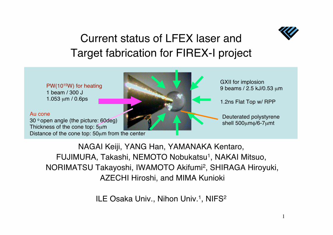
1 Current status of LFEX laser and Target fabrication for FIREX-I project NAGAI Keiji, YANG Han, YAMANAKA Kentaro, FUJIMURA, Takashi, NEMOTO Nobukatsu 1 , NAKAI Mitsuo, NORIMATSU Takayoshi, IWAMOTO Akifumi 2 , SHIRAGA Hiroyuki, AZECHI Hiroshi, and MIMA Kunioki ILE Osaka Univ., Nihon Univ. 1 , NIFS 2 PW(10 15 W) for heating 1 beam / 300 J 1.053 μm / 0.6ps GXII for implosion 9 beams / 2.5 kJ/0.53 μm 1.2ns Flat Top w/ RPP Deuterated polystyrene shell 500μm /6-7μmt Au cone 30 o open angle (the picture: 60deg) Thickness of the cone top: 5μm Distance of the cone top: 50μm from the center
Transcript of Current status of LFEX laser and Target fabrication for ...mw2007ta.lebedev.ru/data/17...
1
Current status of LFEX laser andTarget fabrication for FIREX-I project
NAGAI Keiji, YANG Han, YAMANAKA Kentaro,FUJIMURA, Takashi, NEMOTO Nobukatsu1, NAKAI Mitsuo,
NORIMATSU Takayoshi, IWAMOTO Akifumi2, SHIRAGA Hiroyuki, AZECHI Hiroshi, and MIMA Kunioki
ILE Osaka Univ., Nihon Univ.1, NIFS2
PW(1015W) for heating1 beam / 300 J1.053 μm / 0.6ps
GXII for implosion9 beams / 2.5 kJ/0.53 μm
1.2ns Flat Top w/ RPP
Deuterated polystyreneshell 500μm /6-7μmt
Au cone 30 o open angle (the picture: 60deg)Thickness of the cone top: 5μmDistance of the cone top: 50μm from the center
2
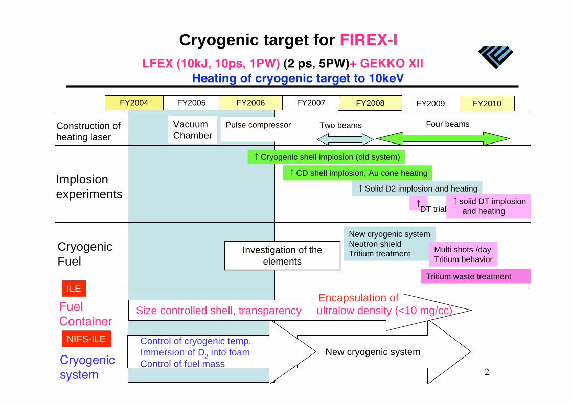
Cryogenic target for FIREX-I
FY2008 FY2009 FY2010FY2007
Construction of
heating laser
Four beamsTwo beams
Implosion
experiments
CD shell implosion, Au cone heating
Solid D2 implosion and heating
solid DT implosion
and heating
Cryogenic
Fuel
New cryogenic system
Neutron shield
Tritium treatmentMulti shots /day
Tritium behavior
Tritium waste treatment
DT trial
FY2005 FY2006
Vacuum
Chamber
Pulse compressor
Investigation of the
elements
Cryogenicsystem
Control of cryogenic temp.
Immersion of D2 into foam
Control of fuel mass
NIFS-ILE
FuelContainer
Size controlled shell, transparency ultralow density (<10 mg/cc)
ILE
FY2004
Cryogenic shell implosion (old system)
New cryogenic system
LFEX (10kJ, 10ps, 1PW) (2 ps, 5PW)+ GEKKO XII Heating of cryogenic target to 10keV
Encapsulation of
3
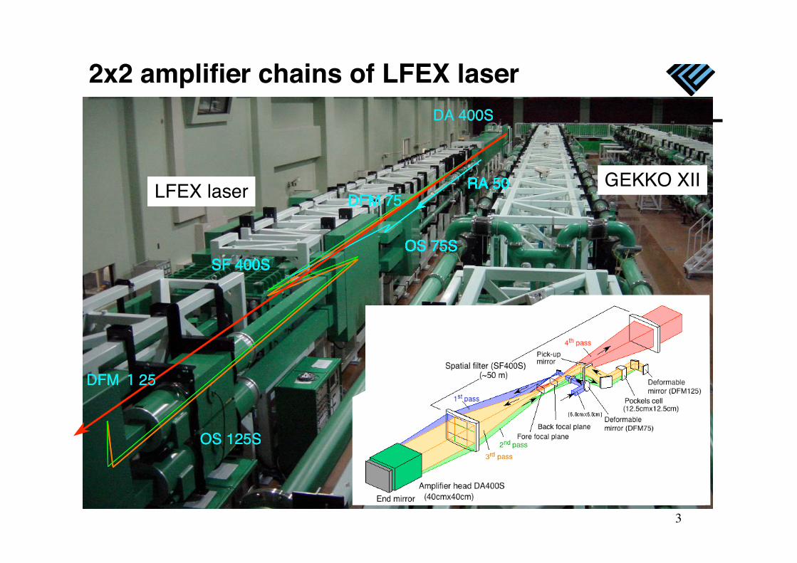
2x2 amplifier chains of LFEX laser
LFEX laser RA 50
OS 75S
RA 50
OS 75S
DFM 75RA 50
OS 75S
DA 400S
SF 400S
DFM 75RA 50
OS 75S
DA 400S
SF 400S
DFM 75RA 50LFEX laser
OS 75S
OS 125S
DA 400S
SF 400S
DFM 75RA 50
DFM 25
LFEX laser
OS 75S
OS 125S
DA 400S
SF 400S
DFM 75RA 50
DFM 25
LFEX laser
OS 75S
OS 125S
DA 400S
SF 400S
DFM 75RA 50
DFM 25
GEKKO XII
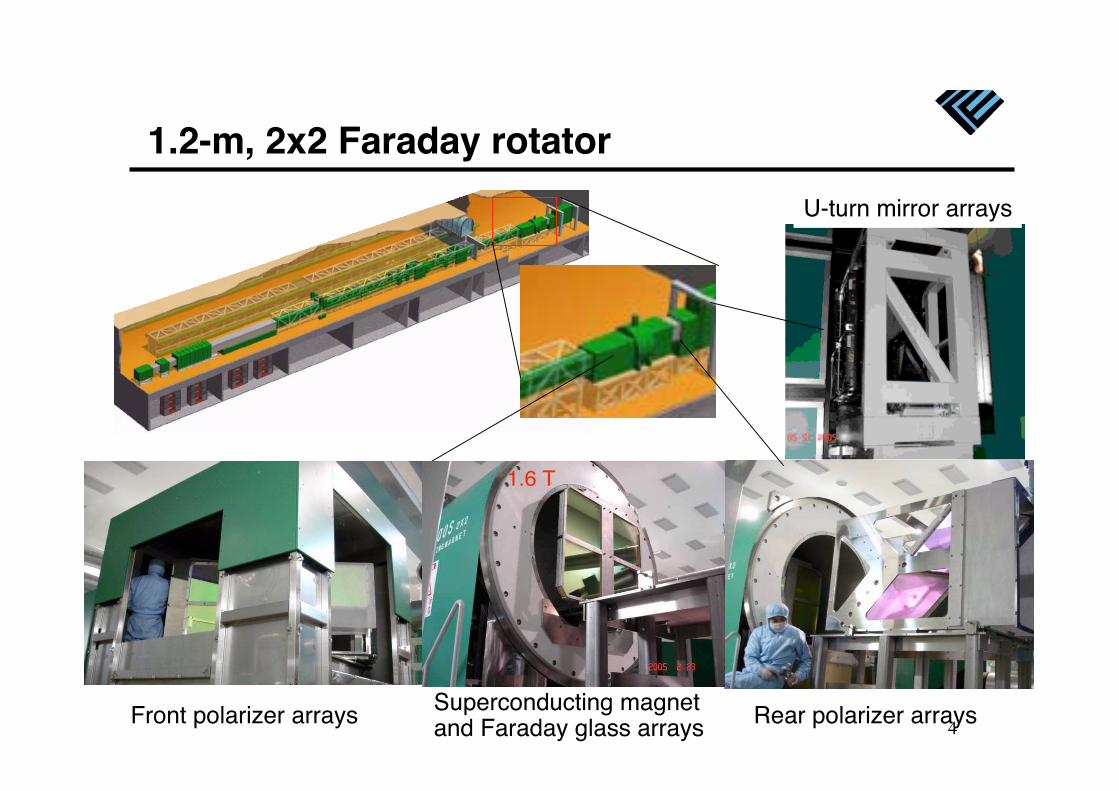
4Front polarizer arrays
U-turn mirror arrays
1.2-m, 2x2 Faraday rotator
Rear polarizer arraysSuperconducting magnetand Faraday glass arrays
1.6 T
5
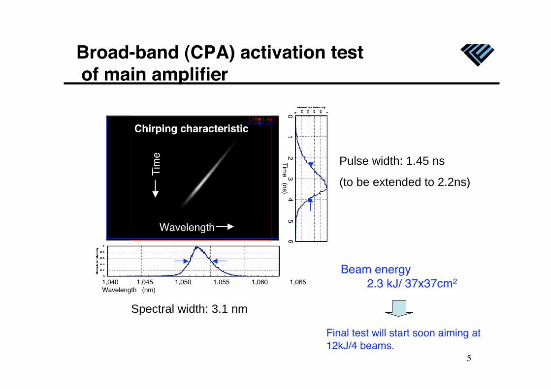
Pulse width: 1.45 ns
(to be extended to 2.2ns)
Spectral width: 3.1 nm
Broad-band (CPA) activation test of main amplifier
Wavelength
1,040 1,045 1,050 1,055 1,060 1,065Wavelength (nm)
01
23
45
6T
ime (ns)
Chirping characteristic
Tim
e
Beam energy 2.3 kJ/ 37x37cm2
Final test will start soon aiming at12kJ/4 beams.
6
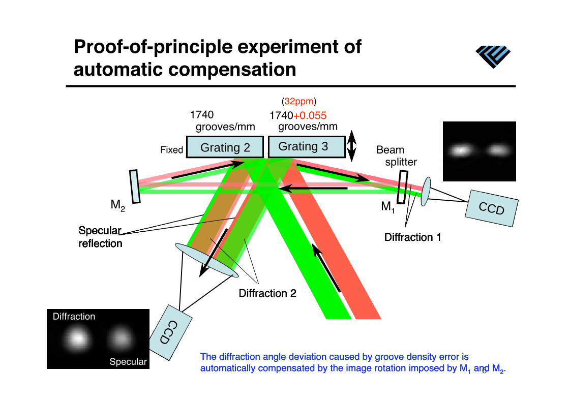
Proof-of-principle experiment of automatic compensation
Beam splitter
Grating 2 Grating 3
1740 grooves/mm
1740+0.055 grooves/mm
M1M2
Fixed
(32ppm)
CC
D
Grating 2 Grating 3
Specularreflection
Specular
M2
CC
D
Grating 2
Specularreflection
Diffraction 2
CCD
Grating 3
Diffraction 1
Specular
M2
CC
D
CCD
Grating 2 Grating 3
Specularreflection
Diffraction 2
Diffraction 1
The diffraction angle deviation caused by groove density error isautomatically compensated by the image rotation imposed by M1 and M2.
Specular
M2
CC
D
CCD
Grating 2 Grating 3
Specularreflection
Diffraction 2
Diffraction 1
The diffraction angle deviation caused by groove density error isautomatically compensated by the image rotation imposed by M1 and M2.
Diffraction
Specular
M2
7
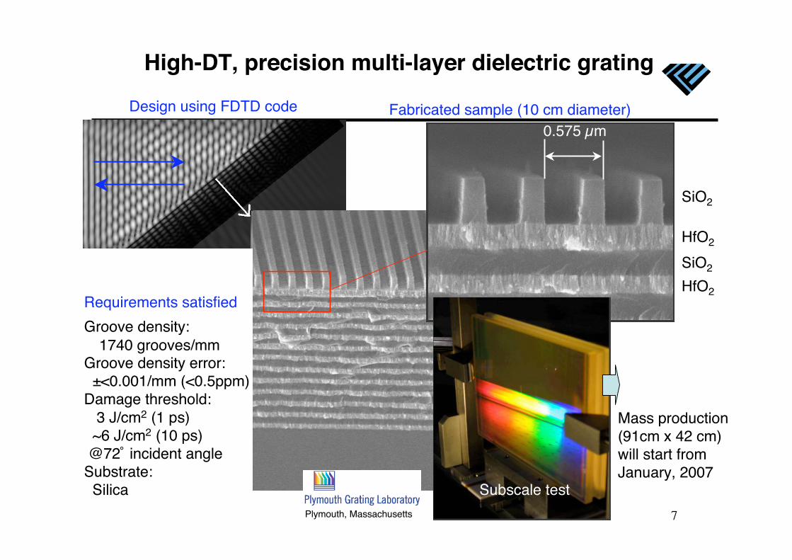
High-DT, precision multi-layer dielectric grating
Groove density:1740 grooves/mm
Groove density error: ±<0.001/mm (<0.5ppm)Damage threshold: 3 J/cm2 (1 ps) ~6 J/cm2 (10 ps) @72˚ incident angleSubstrate: Silica
SiO2
HfO2
SiO2
HfO2
0.575 μm
Requirements satisfied
Design using FDTD code Fabricated sample (10 cm diameter)
Subscale test
Mass production(91cm x 42 cm)will start fromJanuary, 2007
Plymouth, Massachusetts
8
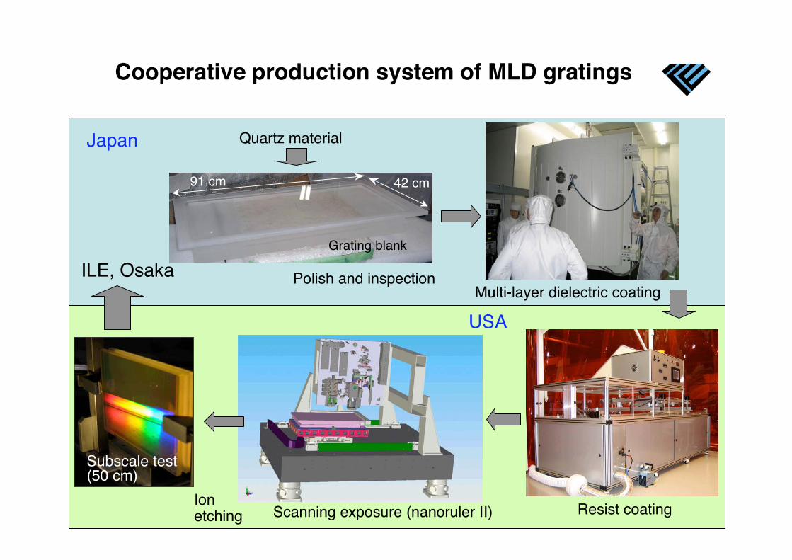
Cooperative production system of MLD gratings
Grating blank
91 cm 42 cm
Ionetching Scanning exposure (nanoruler II) Resist coating
Multi-layer dielectric coatingPolish and inspection
Subscale test(50 cm)
Quartz material
ILE, Osaka
Japan
USA
9
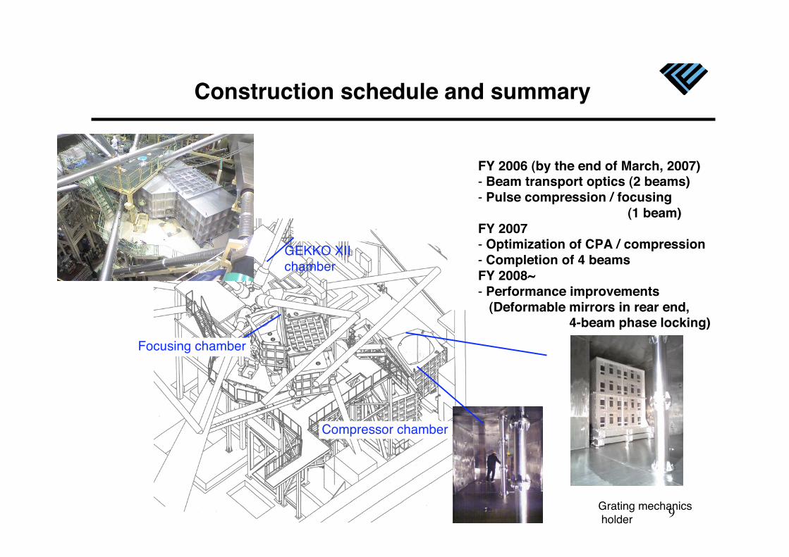
Construction schedule and summary
FY 2006 (by the end of March, 2007)- Beam transport optics (2 beams)- Pulse compression / focusing (1 beam)FY 2007- Optimization of CPA / compression- Completion of 4 beamsFY 2008~- Performance improvements (Deformable mirrors in rear end, 4-beam phase locking)
Focusing chamber
GEKKO XIIchamber
Compressor chamber
Grating mechanics holder
Focusing chamber
10
1. Introduction of LFEX2. Specification of target for FIREX-I3. Materials for the processes … RF and a new
derivative4. Catalyst of gelation…phase transfer catalyst5. Deformation of emulsion6. Characterization7. Hole drilling and attaching cone
11
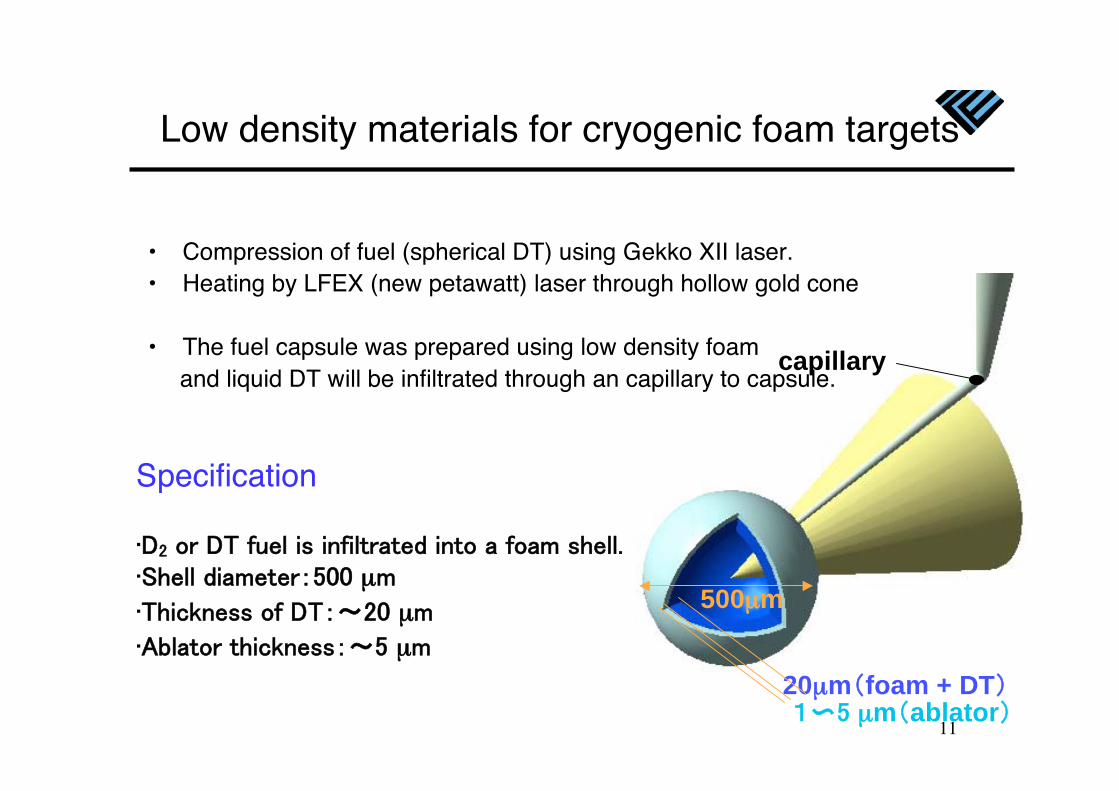
Specification
μ
μ
μ
500μm
20μm foam + DT μm ablator
capillary
• Compression of fuel (spherical DT) using Gekko XII laser.• Heating by LFEX (new petawatt) laser through hollow gold cone
• The fuel capsule was prepared using low density foam and liquid DT will be infiltrated through an capillary to capsule.
Low density materials for cryogenic foam targets
12
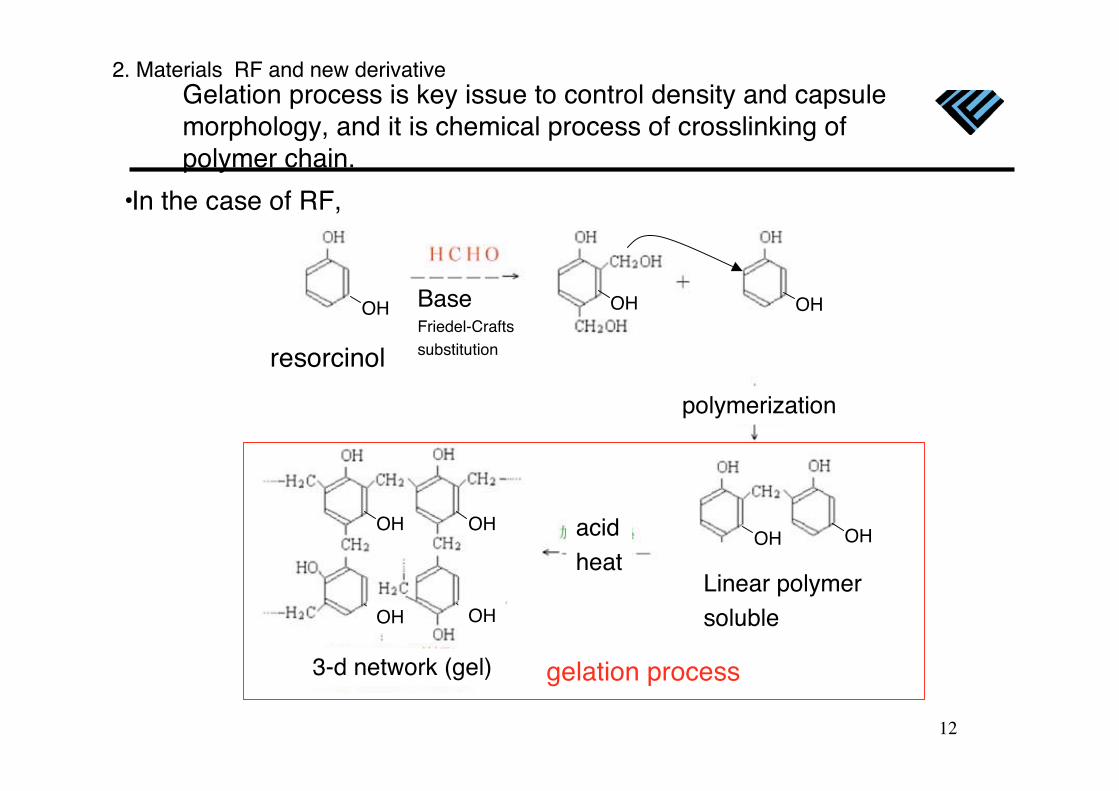
Gelation process is key issue to control density and capsulemorphology, and it is chemical process of crosslinking ofpolymer chain.
resorcinol
OH BaseFriedel-Craftssubstitution
OH OH
OH OH
OH OH
OH
OH
polymerization
OH
Linear polymersoluble
acidheat
3-d network (gel)
•In the case of RF,
gelation process
2. Materials RF and new derivative
13
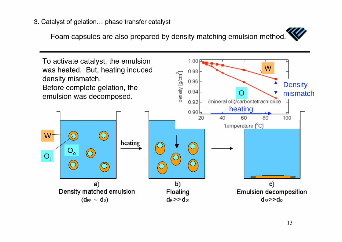
Foam capsules are also prepared by density matching emulsion method.
heating
Density
mismatch
W
Oo
O
W
~
Oi
To activate catalyst, the emulsionwas heated. But, heating induceddensity mismatch.Before complete gelation, theemulsion was decomposed.
3. Catalyst of gelation… phase transfer catalyst
14
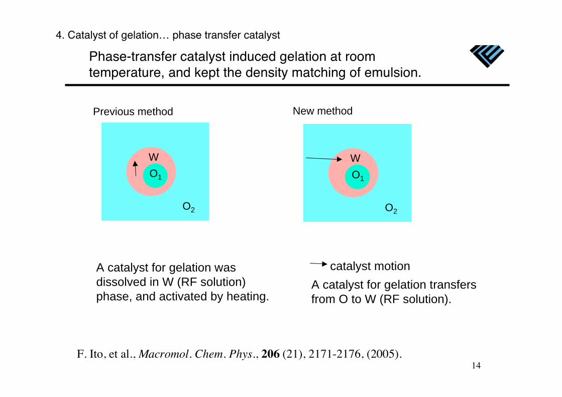
Phase-transfer catalyst induced gelation at roomtemperature, and kept the density matching of emulsion.
A catalyst for gelation transfers
from O to W (RF solution).
catalyst motion
F. Ito, et al., Macromol. Chem. Phys., 206 (21), 2171-2176, (2005).
Previous method New method
O2
O1
W
O2
O1
W
A catalyst for gelation was
dissolved in W (RF solution)
phase, and activated by heating.
4. Catalyst of gelation… phase transfer catalyst
15
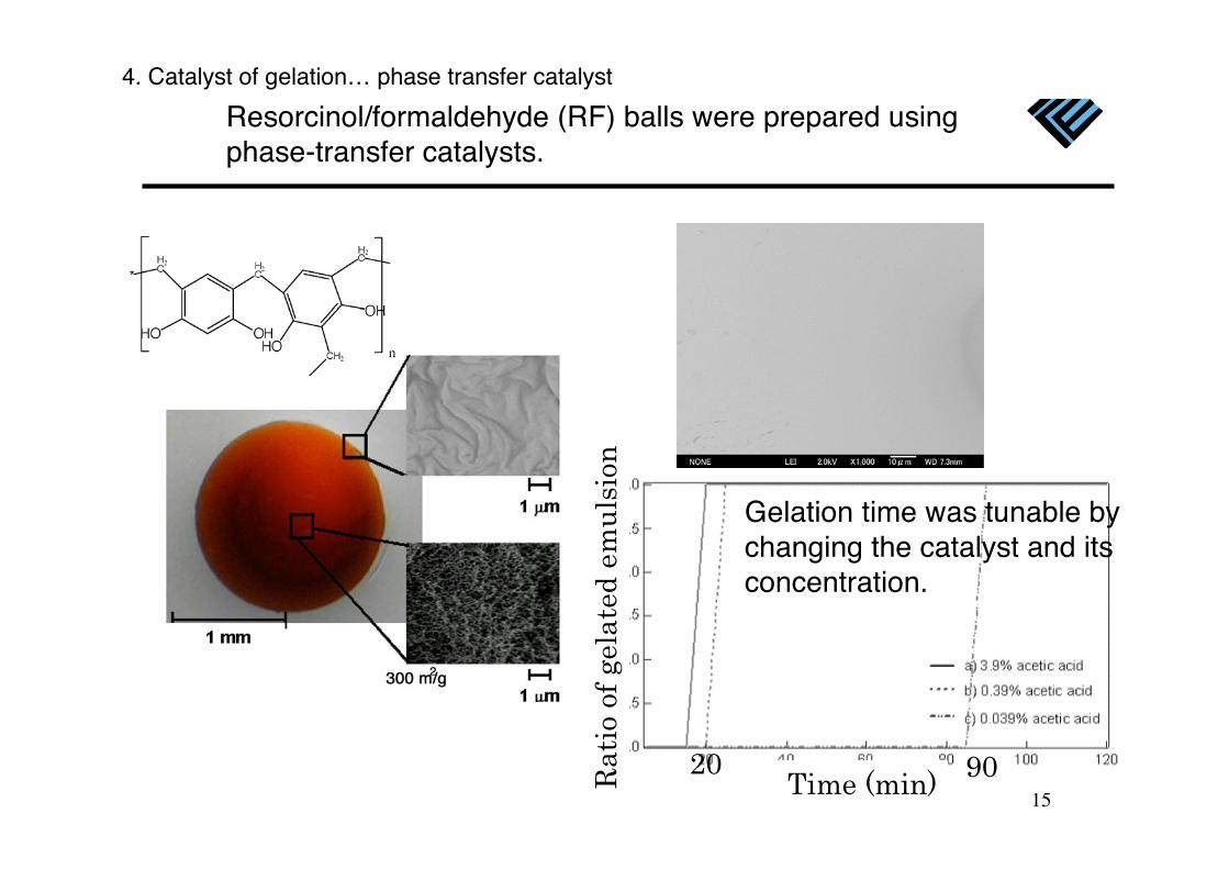
Resorcinol/formaldehyde (RF) balls were prepared usingphase-transfer catalysts.
Surface image of a RF ball
Gelation time was tunable bychanging the catalyst and itsconcentration.
4. Catalyst of gelation… phase transfer catalyst
20 90Time (min)R
ati
o of
gel
ate
d e
mu
lsio
n
16
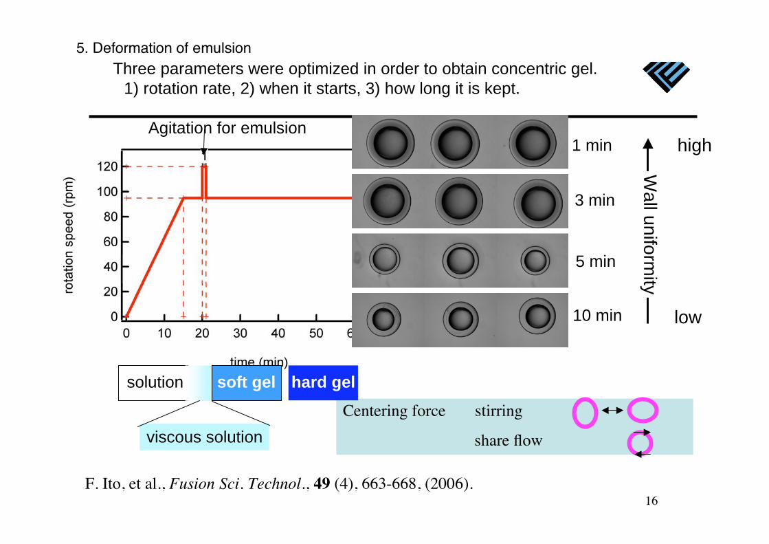
Centering force stirring
share flow
1 min
3 min
5 min
10 min
Agitation for emulsionW
all u
nifo
rmity
high
low
F. Ito, et al., Fusion Sci. Technol., 49 (4), 663-668, (2006).
solution hard gelsoft gel
viscous solution
Three parameters were optimized in order to obtain concentric gel.
1) rotation rate, 2) when it starts, 3) how long it is kept.
5. Deformation of emulsion
17
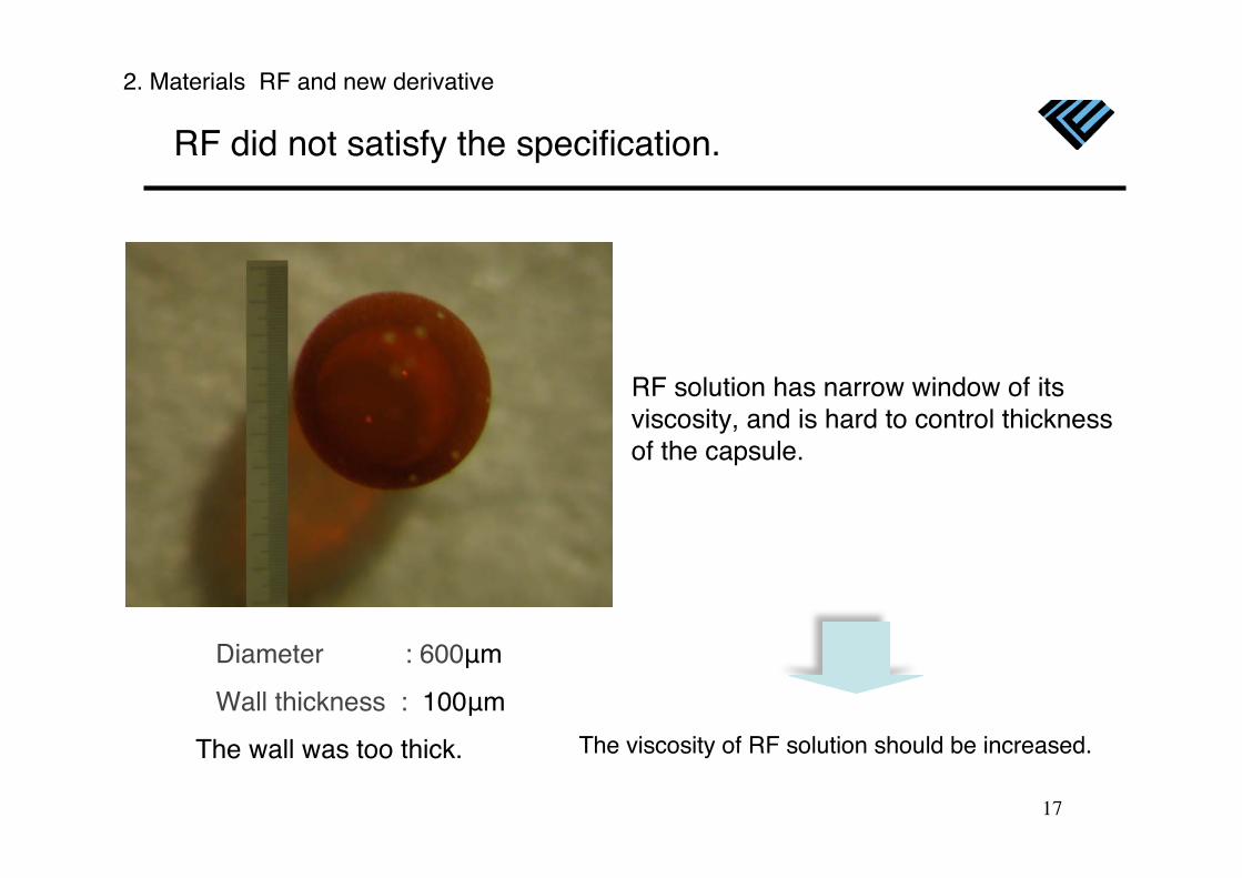
The wall was too thick. The viscosity of RF solution should be increased.
RF did not satisfy the specification.
Diameter : 600 m
Wall thickness : 100 m
RF solution has narrow window of itsviscosity, and is hard to control thicknessof the capsule.
2. Materials RF and new derivative
18
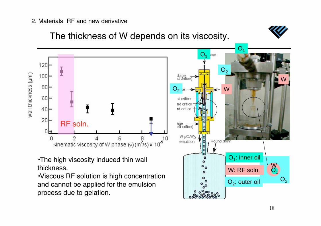
•The high viscosity induced thin wallthickness.•Viscous RF solution is high concentrationand cannot be applied for the emulsionprocess due to gelation.
The thickness of W depends on its viscosity.O1
W
O2
O2
O1
W
O1: inner oil
O2: outer oil
W: RF soln.
RF soln.
2. Materials RF and new derivative
O1
WO2
19
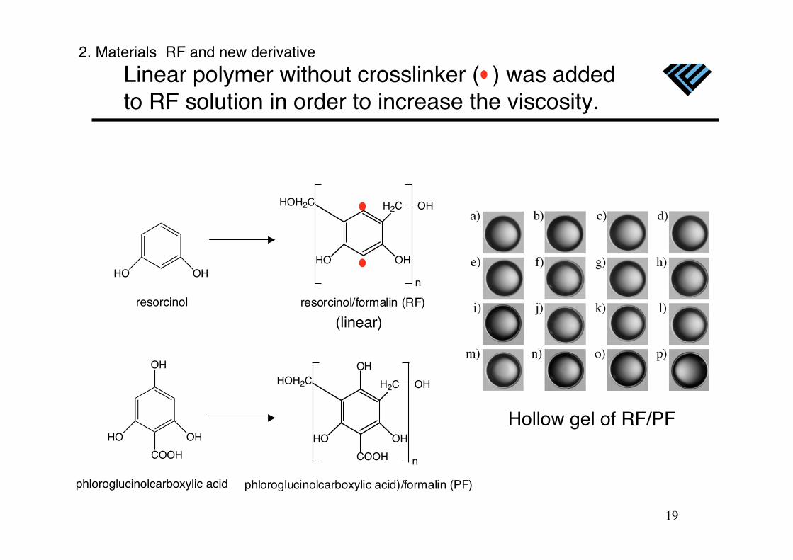
Linear polymer without crosslinker ( ) was addedto RF solution in order to increase the viscosity.
COOH
HO OH
OHHOH2C H2C OH
n
phloroglucinolcarboxylic acid)/formalin (PF)
HO OH
HOH2C H2C OH
n
resorcinol/formalin (RF)
COOH
HO OH
OH
phloroglucinolcarboxylic acid
HO OH
resorcinol
(linear)
Hollow gel of RF/PF
2. Materials RF and new derivative
20
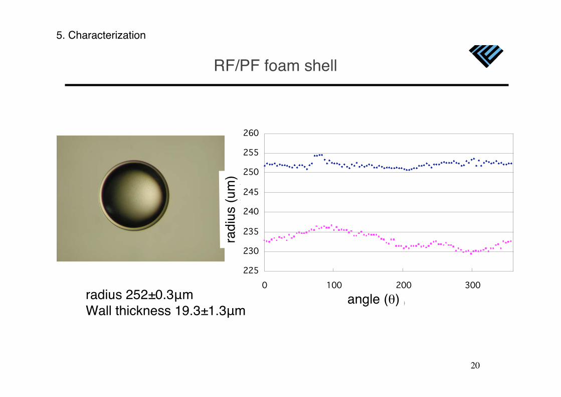
radius 252±0.3 mWall thickness 19.3±1.3 m
RF/PF foam shell
radi
us (
um)
angle ( )
5. Characterization
21
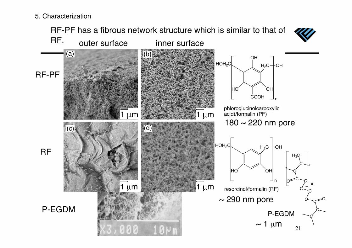
RF-PF has a fibrous network structure which is similar to that ofRF. outer surface inner surface
RF-PF
RF
P-EGDM
C
C*
C
*
O
C C
H3C
O
C
C
CO O
n
P-EGDM
5. Characterization
~ 1 μm
180 ~ 220 nm pore
~ 290 nm pore
22
S-1
S-2
S-3
A-2
A-3
A-1
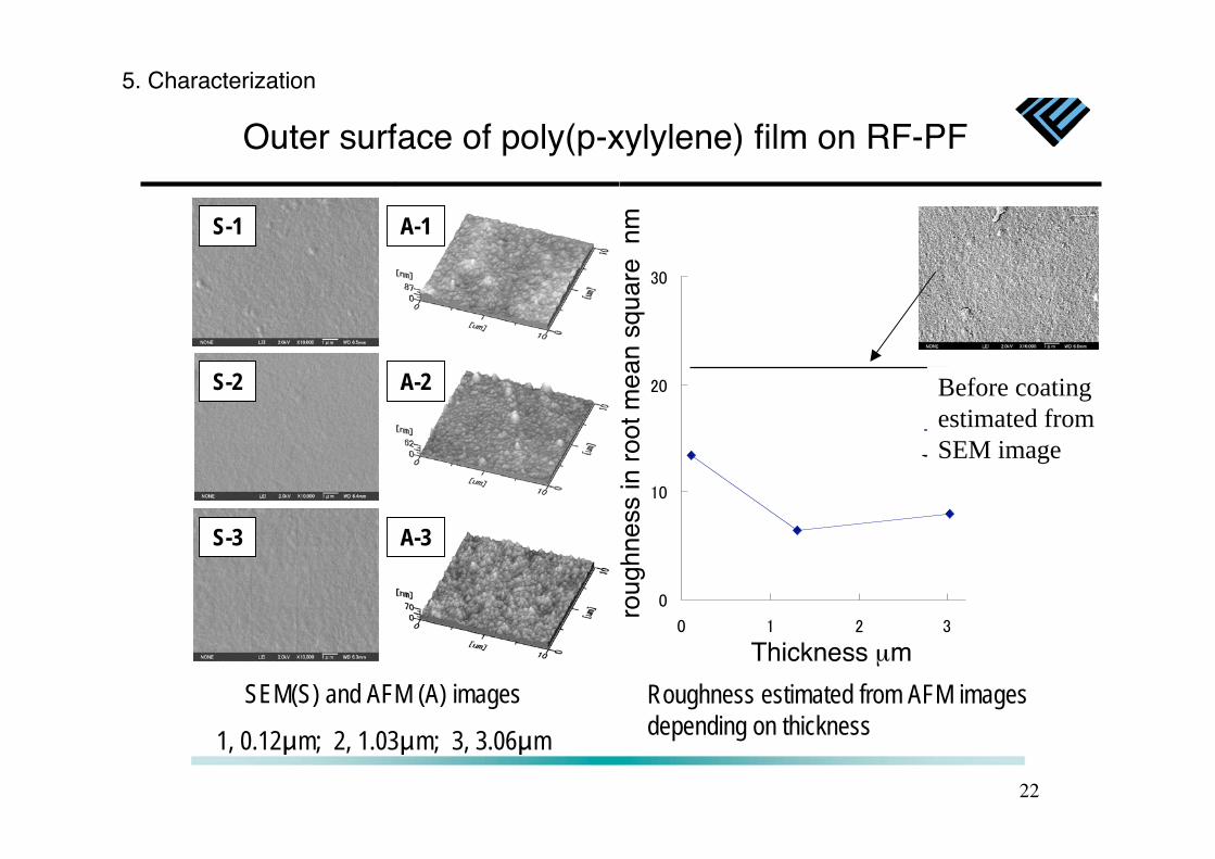
Outer surface of poly(p-xylylene) film on R F-PF
Before coating
estimated from
SEM image
SEM(S) and AFM (A) images
1, 0.12 m; 2, 1.03 m; 3, 3.06 m
Roughness estimated from AFM images
depending on thickness
Thickness μmro
ughn
ess
in r
oot m
ean
squa
re n
m
5. Characterization
23
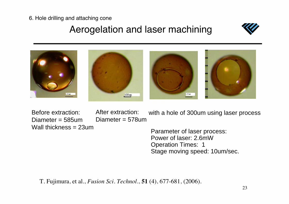
Aerogelation and laser machining
Before extraction:
Diameter = 585um
Wall thickness = 23um
After extraction:
Diameter = 578umwith a hole of 300um using laser process
Parameter of laser process:Power of laser: 2.6mWOperation Times: 1Stage moving speed: 10um/sec.
6. Hole drilling and attaching cone
T. Fujimura, et al., Fusion Sci. Technol., 51 (4), 677-681, (2006).
24
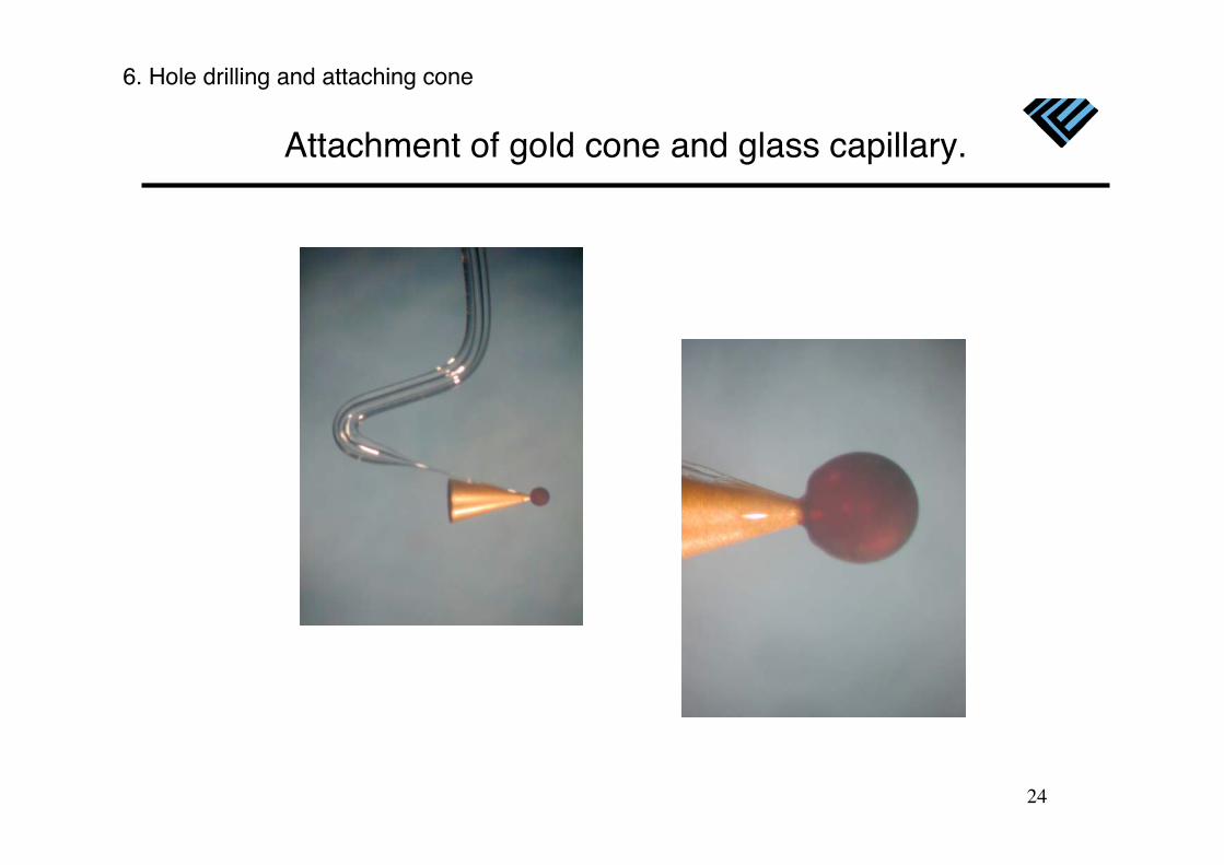
Attachment of gold cone and glass capillary.
140 μm
6. Hole drilling and attaching cone
25
1 mm
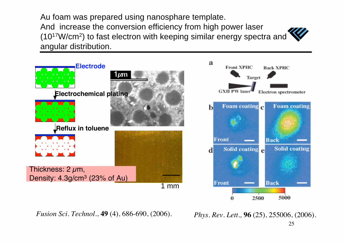
Au foam was prepared using nanosphare template.
And increase the conversion efficiency from high power laser
(1017W/cm2) to fast electron with keeping similar energy spectra and
angular distribution.
Electrochemical plating
Reflux in toluene
Electrode
Thickness: 2 μm,Density: 4.3g/cm3 (23% of Au)
Fusion Sci. Technol., 49 (4), 686-690, (2006). Phys. Rev. Lett., 96 (25), 255006, (2006).
26
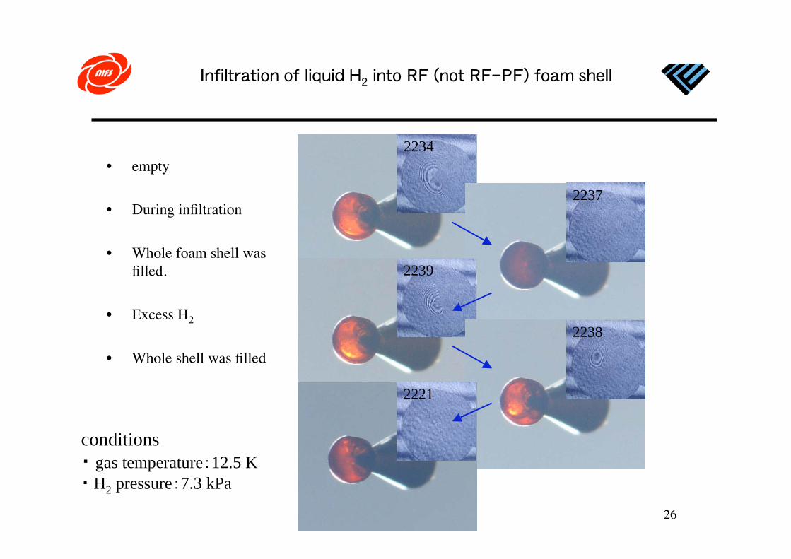
• empty
• During infiltration
• Whole foam shell wasfilled.
• Excess H2
• Whole shell was filled
2234
2237
2239
2238
2221
conditions
gas temperature 12.5 K
H2 pressure 7.3 kPa
27
μ μ
Summary
28
Several kinds of foam materials have been investigated.
poly(4-methyl-1-pentene)
Coagulant foam density disk size (mg/cm3) (μm)___________________________________________1-hexanol 12 ~102-methyl-1-pentanol 5.0 ~32-ethyl-1-butanol 2.0 ~61-butanol ~3 ~12-butanol ~3 ~22-methyl-1-propanol ~3 ~12-methyl-2-propanol ~3 <1___________________________________________
CHCH2
HC
CH2
CH3H3C n
Foam Materials: Future Plan
In the case of FI, heating efficiency isprimary no dependence with the foamdensity. As the result, the gain directlydepends on the density and driver energy.
29
a
New Stamp
a
Text Box
NAGAI Keiji