Cryogenic system for the MYRRHA linac Nicolas Chevalier Tomas Junquera 20.10.2012.
32
Cryogenic system for the MYRRHA linac Nicolas Chevalier Tomas Junquera 20.10.2012
-
Upload
cameron-harrison -
Category
Documents
-
view
218 -
download
0
Transcript of Cryogenic system for the MYRRHA linac Nicolas Chevalier Tomas Junquera 20.10.2012.
Cryogenic system for the MYRRHA linac
Nicolas ChevalierTomas Junquera
20.10.2012
Part 1
Heat load budget and operating temperature
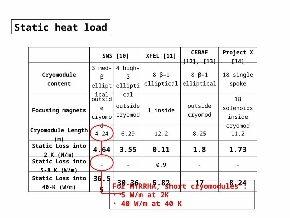
Static heat load
For MYRRHA, short cryomodules : • 5 W/m at 2K• 40 W/m at 40 K
SNS [10] XFEL [11] CEBAF [12], [13] Project X [14]
Cryomodule content 3 med-β elliptical
4 high-β elliptical 8 β=1 elliptical 8 β=1 elliptical 18 single spoke
Focusing magnets outside cryomod
outside cryomod 1 inside outside
cryomod18 solenoids
inside cryomod
Cryomodule Length (m) 4.24 6.29 12.2 8.25 11.2
Static Loss into 2 K (W/m) 4.64 3.55 0.11 1.8 1.73
Static Loss into 5-8 K (W/m) - - 0.9 - -
Static Loss into 40-K (W/m) 36.55 30.36 5.82 17 8.24
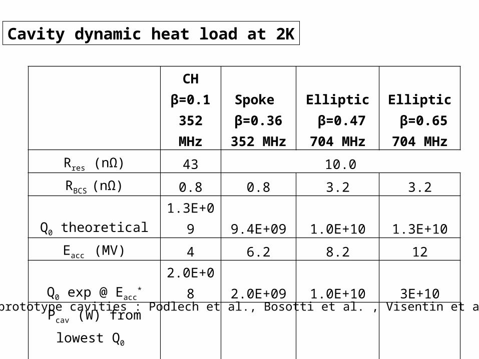
CHβ=0.1
352 MHz
Spoke β=0.36
352 MHz
Elliptic β=0.47
704 MHz
Elliptic β=0.65
704 MHzRres (nΩ) 43 10.0RBCS (nΩ) 0.8 0.8 3.2 3.2
Q0 theoretical 1.3E+09 9.4E+09 1.0E+10 1.3E+10Eаcc (MV) 4 6.2 8.2 12
Q0 exp @ Eacc* 2.0E+08 2.0E+09 1.0E+10 3E+10
Pcav (W) from lowest Q0 including +1 W coupler
conduction 11 8.9 11.3 15.5
Cavity dynamic heat load at 2K
* Values from prototype cavities : Podlech et al., Bosotti et al. , Visentin et al., Olry et al.
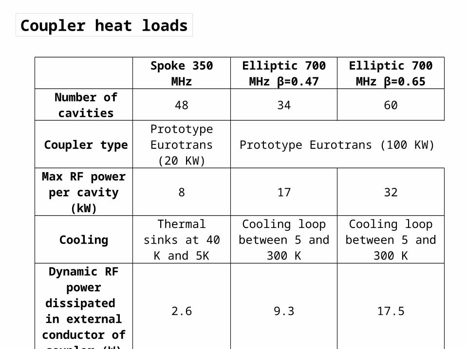
Spoke 350 MHz Elliptic 700 MHz β=0.47
Elliptic 700 MHz β=0.65
Number of cavities 48 34 60
Coupler type Prototype Eurotrans (20 KW) Prototype Eurotrans (100 KW)
Max RF power per cavity (kW) 8 17 32
Cooling Thermal sinks at 40 K and 5K
Cooling loop between 5 and 300
K
Cooling loop between 5 and 300
K
Dynamic RF power dissipated in
external conductor of coupler (W)
2.6 9.3 17.5
Static + Dynamic Load (W)
8 W @ 40 K1.15 W @ 5K 10 W @5K-300K 10 W @ 5K-300K
Coupler heat loads
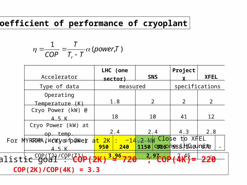
Coefficient of performance of cryoplant
Accelerator LHC (one sector) SNS Project X XFEL
Type of data measured specifications
Operating Temperature (K) 1.8 2 2 2Cryo Power (kW) @ 4.5 K 18 10 41 12
Cryo Power (kW) at op. temp. 2.4 2.4 4.3 2.8
COP (W/W) of 2K | 4.5 K 950 240 1150 386 588 240 870 -
COP(T2)/COP(T1) 3.96 2.97 2.45 -
),(1
TpowerTT
T
COP r
For MYRRHA, cryo power at 2K : ~14.2 kW Close to XFEL or one LHC unit
Realistic goal : COP(2K) = 720 ; COP(4K)= 220 COP(2K)/COP(4K) = 3.3
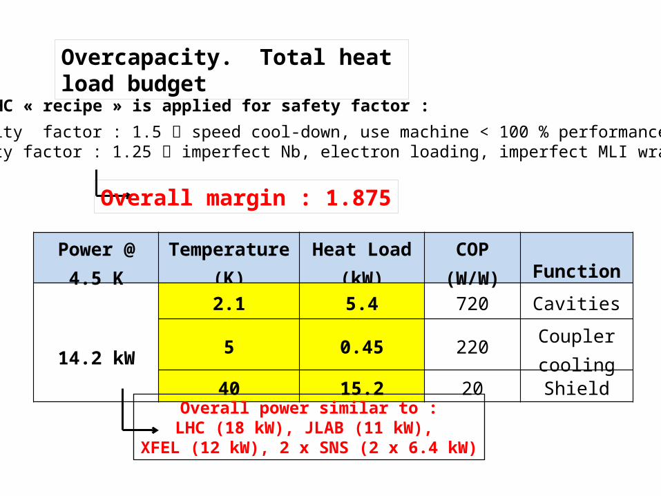
Overcapacity. Total heat load budget
Power @ 4.5 K Temperature (K) Heat Load (kW) COP (W/W) Function
2.1 5.4 720 Cavities
14.2 kW5 0.45 220 Coupler
cooling
40 15.2 20 Shield
Overcapacity factor : 1.5 speed cool-down, use machine < 100 % performanceUncertainty factor : 1.25 imperfect Nb, electron loading, imperfect MLI wrapping etc.
Overall power similar to :LHC (18 kW), JLAB (11 kW),
XFEL (12 kW), 2 x SNS (2 x 6.4 kW)
Overall margin : 1.875
LHC « recipe » is applied for safety factor :
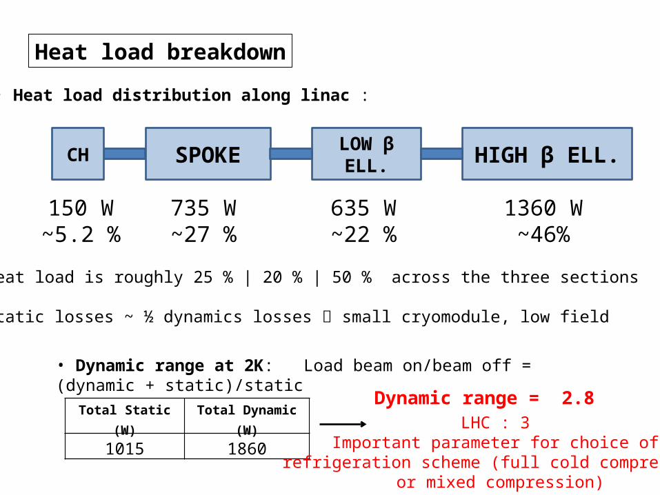
Heat load breakdown
• heat load is roughly 25 % | 20 % | 50 % across the three sections
• static losses ~ ½ dynamics losses small cryomodule, low field
SPOKE HIGH β ELL.LOW β ELL.
735 W~27 %
635 W~22 %
1360 W~46%
Total Static (W) Total Dynamic (W)
1015 1860
• Dynamic range at 2K: Load beam on/beam off = (dynamic + static)/static
Dynamic range = 2.8LHC : 3
Important parameter for choice ofrefrigeration scheme (full cold compression
or mixed compression)
• Heat load distribution along linac :
CH
150 W~5.2 %
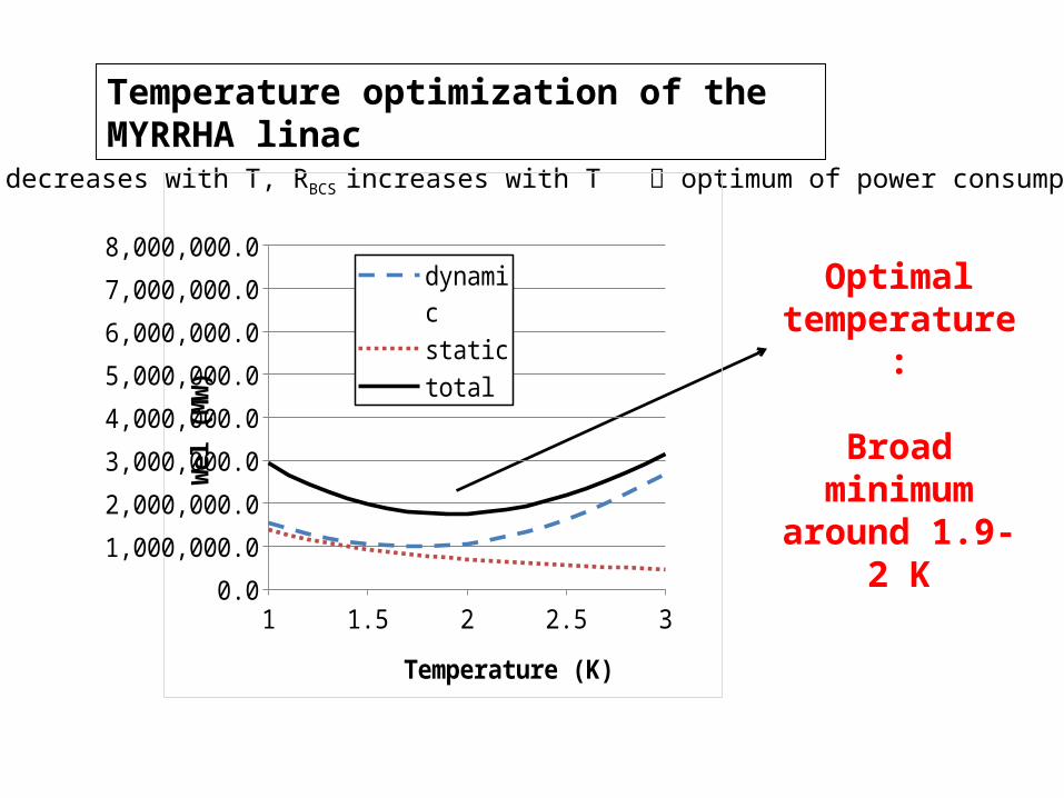
Temperature optimization of the MYRRHA linac
Optimal temperature:
Broad minimum around 1.9-2 K
COP decreases with T, RBCS increases with T optimum of power consumption
1 1.2 1.4 1.6 1.8 2 2.2 2.4 2.6 2.8 30.0
1,000,000.0
2,000,000.0
3,000,000.0
4,000,000.0
5,000,000.0
6,000,000.0
7,000,000.0
8,000,000.0
dynamic
static
total
Temperature (K)
Wel
(MW
)
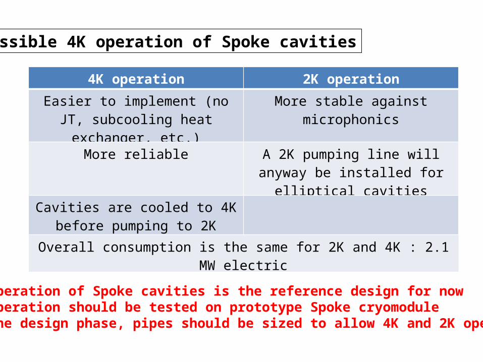
Possible 4K operation of Spoke cavities
4K operation 2K operation
Easier to implement (no JT, subcooling heat exchanger, etc.)
More stable against microphonics
More reliable A 2K pumping line will anyway be installed for elliptical cavities
Cavities are cooled to 4K before pumping to 2K
Overall consumption is the same for 2K and 4K : 2.1 MW electric
2K operation of Spoke cavities is the reference design for now4K operation should be tested on prototype Spoke cryomoduleIn the design phase, pipes should be sized to allow 4K and 2K operation
Part 2
Cryofluid distribution : valve box, transfer line and cool down characteristics
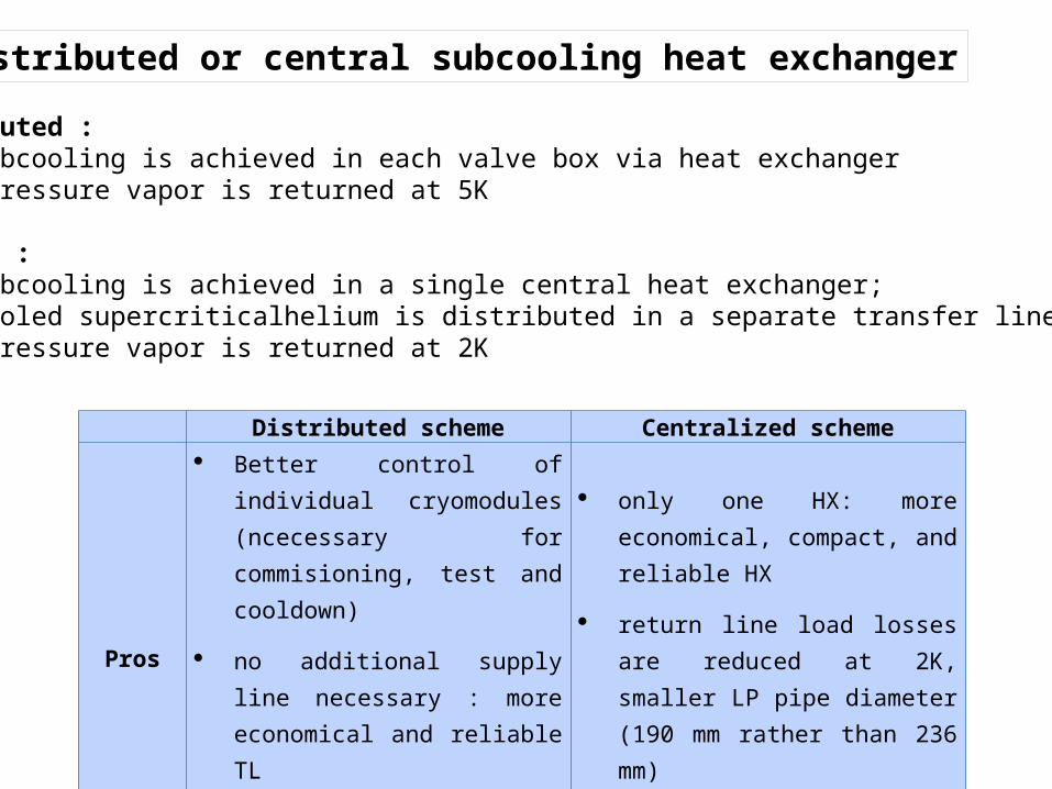
Distributed scheme Centralized scheme
Pros
Better control of individual cryomodules (ncecessary for commisioning, test and cooldown)
no additional supply line necessary : more economical and reliable TL
less heat flux on the 2K level
only one HX: more economical, compact, and reliable HX
return line load losses are reduced at 2K, smaller LP pipe diameter (190 mm rather than 236 mm)
simplified VB design
Adopted by … SNS, LHC, XFEL JLAB (CEBAF)
Distributed or central subcooling heat exchanger
Distributed : • 2K subcooling is achieved in each valve box via heat exchanger• Low pressure vapor is returned at 5K
Central :• 2K subcooling is achieved in a single central heat exchanger; • Subcooled supercriticalhelium is distributed in a separate transfer line• Low pressure vapor is returned at 2K
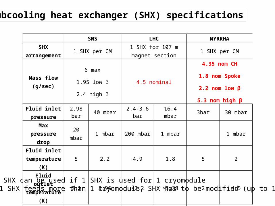
SNS LHC MYRRHASHX
arrangement 1 SHX per CM 1 SHX for 107 m magnet section 1 SHX per CM
Mass flow (g/sec)
6 max
1.95 low β
2.4 high β
4.5 nominal
4.35 nom CH
1.8 nom Spoke
2.2 nom low β
5.3 nom high βFluid inlet pressure
2.98 bar 40 mbar 2.4-3.6 bar 16.4 mbar 3bar 30 mbar
Max pressure drop 20 mbar 1 mbar 200 mbar 1 mbar 1 mbar
Fluid inlet temperature (K) 5 2.2 4.9 1.8 5 2
Fluid outlet temperature (K) 2.1 3.96 <2.2 >3.38 2 4.5
Capacity (W) 60 31 30
Subcooling heat exchanger (SHX) specifications
• LHC SHX can be used if 1 SHX is used for 1 cryomodule• If 1 SHX feeds more than 1 cryomodule, SHX has to be modified (up to 10 g/sec)
40K 4 bar
5K 3bar
4.5K 30 mbar
6K 1.2 bar
80K 3bar
TI
TI
TI
TI
TI
TI
LI
TI
TI
SHX
POTJT
bypass EV
EV
shield
2K header
cavity
beamline
vacuumbarrier
couplerCC loop
CV
SV RD
LI
4K FUVto
con
ditio
ning
CD
TI
TI
TI
TI
TI P
P
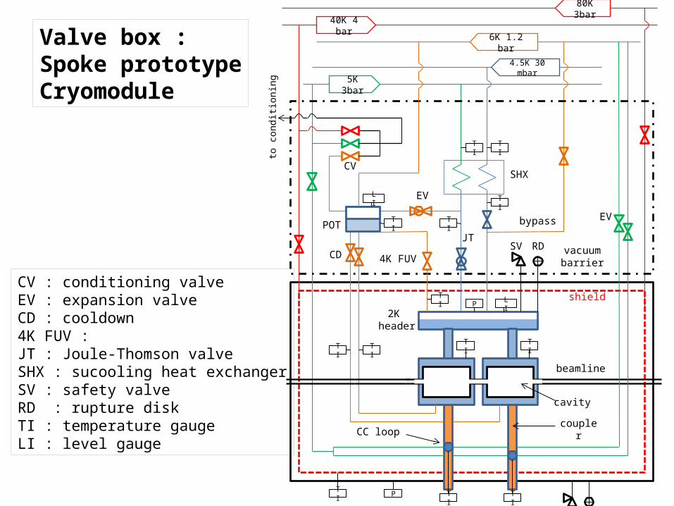
Valve box :Spoke prototypeCryomodule
CV : conditioning valveEV : expansion valveCD : cooldown4K FUV : JT : Joule-Thomson valveSHX : sucooling heat exchangerSV : safety valveRD : rupture diskTI : temperature gaugeLI : level gauge
40K 4 bar
5K 3bar
4.5K 30 mbar
6K 1.2 bar
80K 3bar
TI
TI
TI
TI
TI
TI
LT
TI
TI
P
P
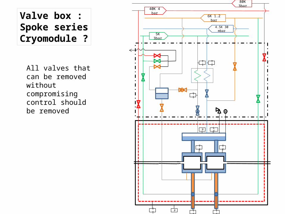
Valve box :Spoke seriesCryomodule ?
All valves that can be removed without compromising control should be removed
40K 4 bar
5K 3bar
4.5K 30 mbar
6K 1.2 bar
80K 3bar
TI
TI
TI
TI
TI
TI
LT
TI
TI
EV
JT
P
P
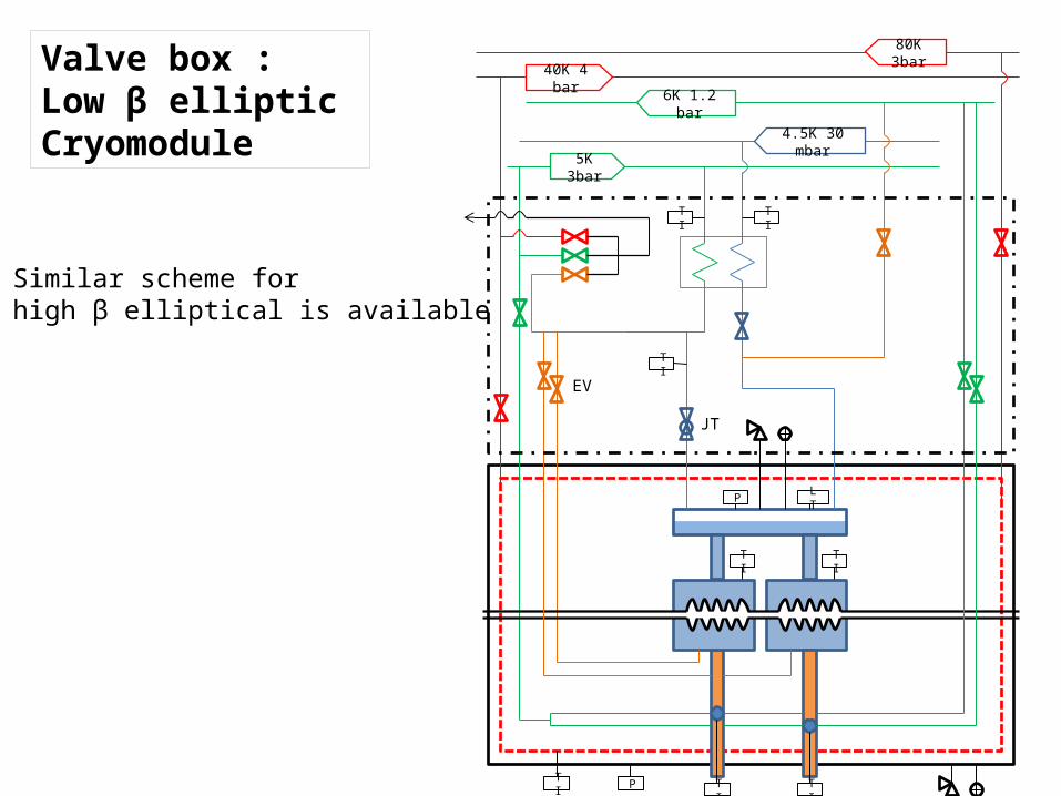
Valve box :Low β elliptic Cryomodule
Similar scheme for high β elliptical is available
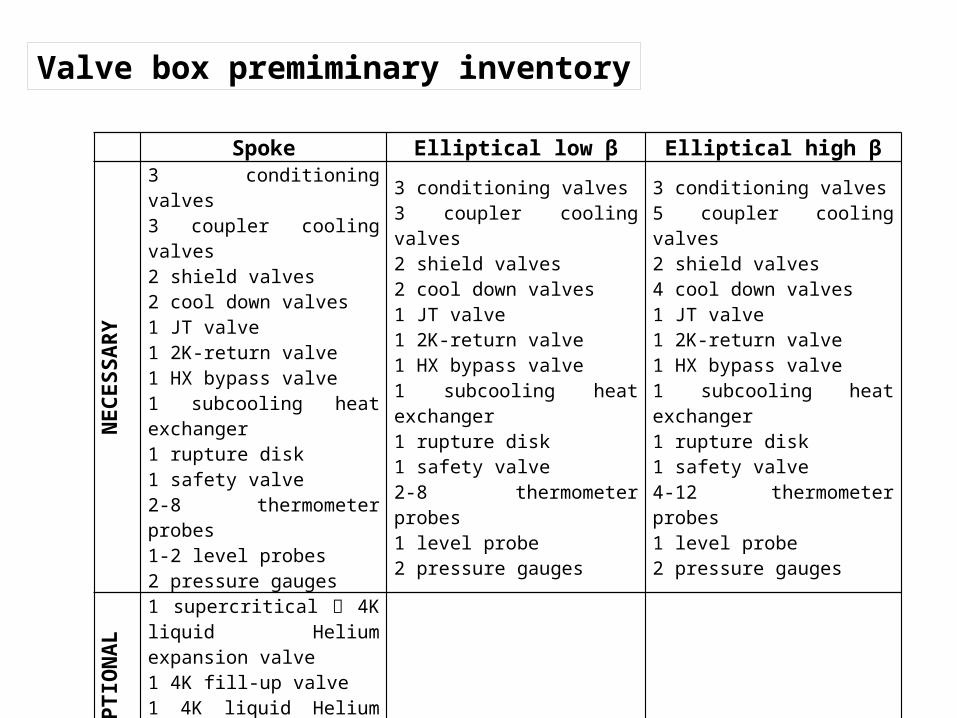
Spoke Elliptical low β Elliptical high β
NECESSARY
3 conditioning valves3 coupler cooling valves2 shield valves2 cool down valves1 JT valve1 2K-return valve1 HX bypass valve1 subcooling heat exchanger1 rupture disk1 safety valve2-8 thermometer probes1-2 level probes2 pressure gauges
3 conditioning valves3 coupler cooling valves2 shield valves2 cool down valves1 JT valve1 2K-return valve1 HX bypass valve1 subcooling heat exchanger1 rupture disk1 safety valve2-8 thermometer probes1 level probe2 pressure gauges
3 conditioning valves5 coupler cooling valves2 shield valves4 cool down valves1 JT valve1 2K-return valve1 HX bypass valve1 subcooling heat exchanger1 rupture disk1 safety valve4-12 thermometer probes1 level probe2 pressure gauges
OPTIONAL
1 supercritical 4K liquid Helium expansion valve1 4K fill-up valve1 4K liquid Helium phase separator (PS)3 warm-up valves
Valve box premiminary inventory
40K 4 bar
5K 3bar
4.5K 30
mbar
6K 1.2 bar
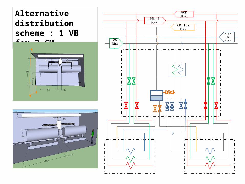
80K 3barAlternative distributionscheme : 1 VB for 2 CM
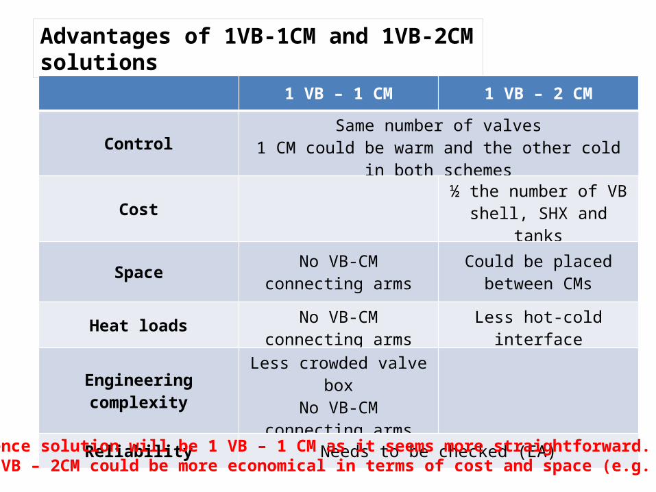
Advantages of 1VB-1CM and 1VB-2CM solutions
1 VB – 1 CM 1 VB – 2 CM
Control Same number of valves1 CM could be warm and the other cold in both schemes
Cost ½ the number of VB shell, SHX and tanks
Space No VB-CM connecting arms Could be placed between CMs
Heat loads No VB-CM connecting arms Less hot-cold interface
Engineering complexity Less crowded valve boxNo VB-CM connecting arms
Reliability Needs to be checked (EA)
Reference solution will be 1 VB – 1 CM as it seems more straightforward.But 1 VB – 2CM could be more economical in terms of cost and space (e.g. ceiling)
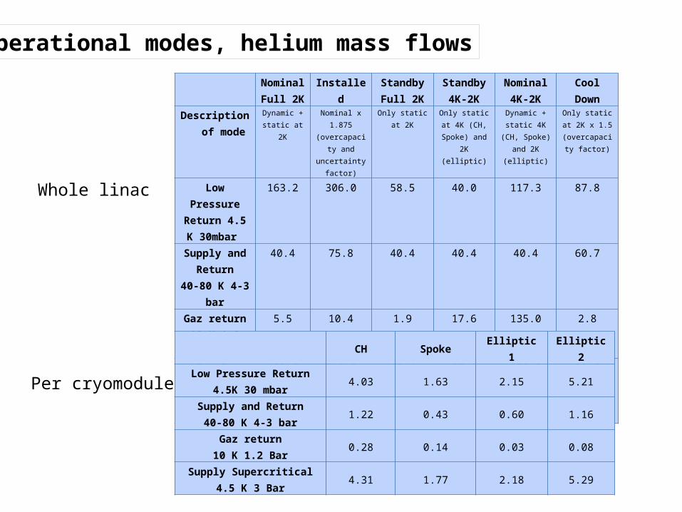
Nominal Full 2K
Installed Standby Full 2K
Standby4K-2K
Nominal 4K-2K
Cool Down
Description of mode
Dynamic + static at 2K
Nominal x 1.875(overcapacity
and uncertainty factor)
Only static at 2K Only static at 4K (CH, Spoke) and
2K (elliptic)
Dynamic + static 4K (CH, Spoke) and 2K (elliptic)
Only static at 2K x 1.5
(overcapacity factor)
Low Pressure Return 4.5 K
30mbar
163.2 306.0 58.5 40.0 117.3 87.8
Supply and Return
40-80 K 4-3 bar
40.4 75.8 40.4 40.4 40.4 60.7
Gaz return10 K 1.2 Bar
5.5 10.4 1.9 17.6 135.0 2.8
Supply Supercritical4.5 K 3 Bar
168.7 316.3 60.4 57.6 252.3 90.6
CH Spoke Elliptic 1 Elliptic 2Low Pressure Return
4.5K 30 mbar 4.03 1.63 2.15 5.21
Supply and Return40-80 K 4-3 bar 1.22 0.43 0.60 1.16
Gaz return10 K 1.2 Bar 0.28 0.14 0.03 0.08
Supply Supercritical4.5 K 3 Bar 4.31 1.77 2.18 5.29
Operational modes, helium mass flows
Whole linac
Per cryomodule
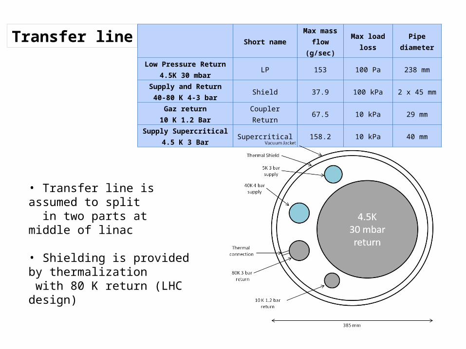
Short name Max mass flow (g/sec) Max load loss Pipe diameter
Low Pressure Return4.5K 30 mbar LP 153 100 Pa 238 mm
Supply and Return40-80 K 4-3 bar Shield 37.9 100 kPa 2 x 45 mm
Gaz return10 K 1.2 Bar Coupler Return 67.5 10 kPa 29 mm
Supply Supercritical4.5 K 3 Bar Supercritical 158.2 10 kPa 40 mm
Transfer line
• Transfer line is assumed to split in two parts at middle of linac
• Shielding is provided by thermalization with 80 K return (LHC design)
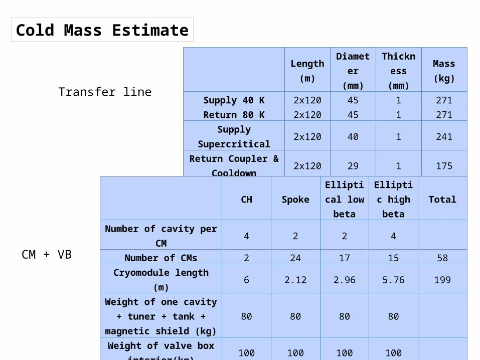
Length (m)
Diameter (mm)
Thickness (mm) Mass (kg)
Supply 40 K 2x120 45 1 271Return 80 K 2x120 45 1 271
Supply Supercritical 2x120 40 1 241Return Coupler &
Cooldown 2x120 29 1 175
Return Low Pressure 2x120 238 3 4306Total 5266
CH Spoke Elliptical low beta
Elliptic high beta Total
Number of cavity per CM 4 2 2 4Number of CMs 2 24 17 15 58
Cryomodule length (m) 6 2.12 2.96 5.76 199Weight of one cavity + tuner + tank + magnetic shield (kg) 80 80 80 80
Weight of valve box interior(kg) 100 100 100 100
Linear Mass/ thermal shield + support post (kg/m) 160 160 100 100
Cold mass per CM (kg) 1380 599.2 556 992Cold Mass of n CMs (kg) 2760 14380.8 9452 14880 41473
Cold Mass Estimate
Transfer line
CM + VB
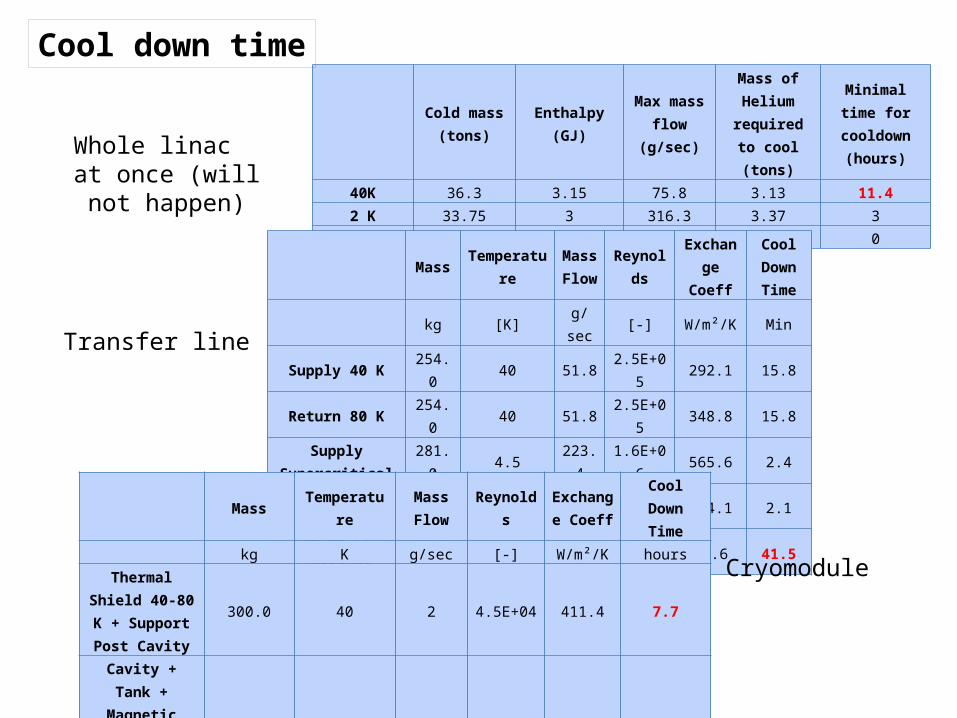
Cold mass (tons) Enthalpy (GJ) Max mass
flow (g/sec)
Mass of Helium
required to cool (tons)
Minimal time for cooldown
(hours)
40K 36.3 3.15 75.8 3.13 11.42 K 33.75 3 316.3 3.37 3
total 70.05 6.15 0 0 0
Mass Temperature Mass Flow Reynolds Exchange
Coeff
Cool Down Time
kg [K] g/sec [-] W/m²/K MinSupply 40 K 254.0 40 51.8 2.5E+05 292.1 15.8Return 80 K 254.0 40 51.8 2.5E+05 348.8 15.8
Supply Supercritical 281.0 4.5 223.4 1.6E+06 565.6 2.4Return Coupler &
Cooldown 248.6 4.5 223.4 1.8E+06 694.1 2.1
Return Low Pressure
4814.6 4.5 223.4 2.8E+05 30.6 41.5
Mass Temperature Mass Flow Reynolds Exchange
CoeffCool Down
Timekg K g/sec [-] W/m²/K hours
Thermal Shield 40-80 K + Support
Post Cavity300.0 40 2 4.5E+04 411.4 7.7
Cavity + Tank + Magnetic Shield +
Tuning System80.0 4.5 1.5 5.5E+04 225.9 2.1
Valve Box inside 100.0 4.5 1.5 4.0E+03 0.3 1.1
Cool down time
Whole linac at once (will not happen)
Transfer line
Cryomodule
Part 3
Cryogenic plant main components
Implantation
Reliability
Preliminary cost analysis
Conclusions
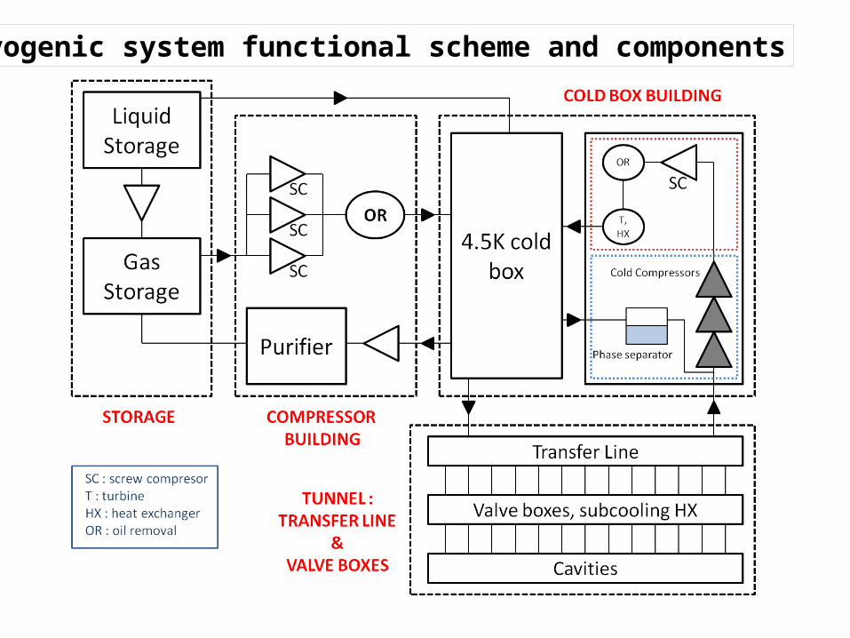
Cryogenic system functional scheme and components
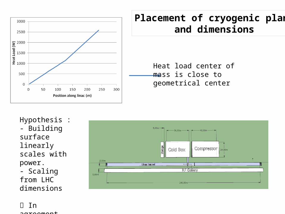
Placement of cryogenic plantand dimensions
Heat load center ofmass is close to geometrical center
Hypothesis : - Building surfacelinearly scales with power. - Scaling from LHC dimensions
In agreement with XFEL (12 kW) dimensions.
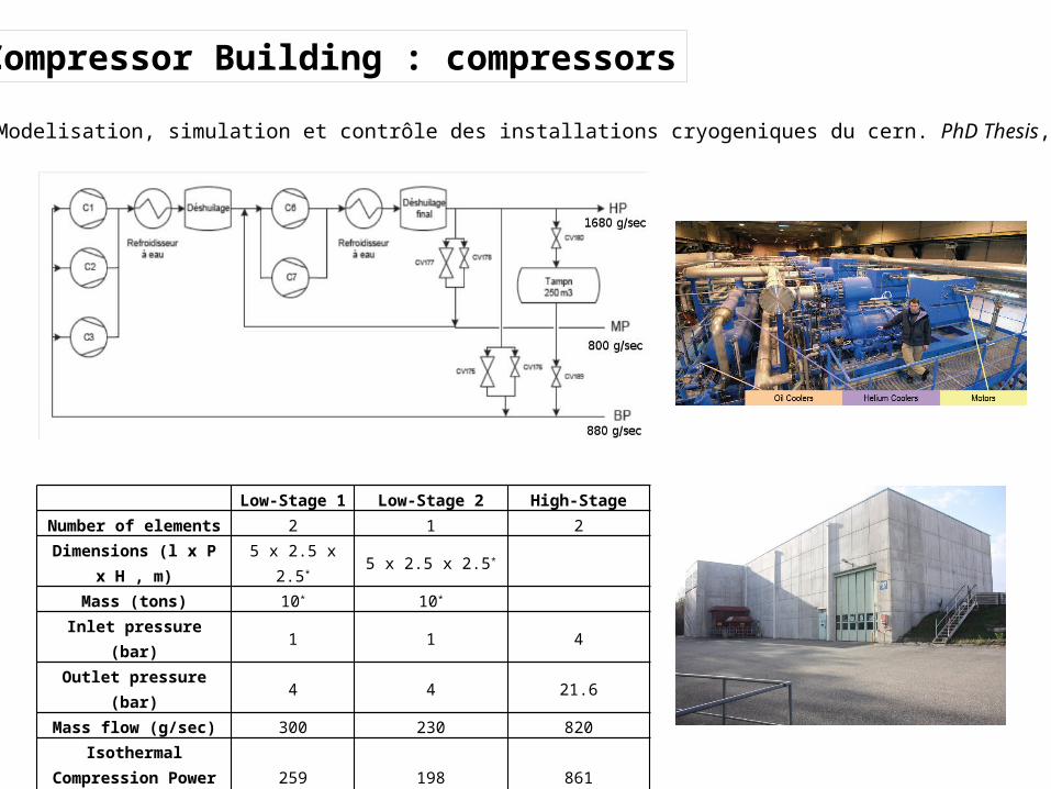
Low-Stage 1 Low-Stage 2 High-StageNumber of elements 2 1 2
Dimensions (l x P x H , m) 5 x 2.5 x 2.5* 5 x 2.5 x 2.5*
Mass (tons) 10* 10*
Inlet pressure (bar) 1 1 4Outlet pressure (bar) 4 4 21.6
Mass flow (g/sec) 300 230 820Isothermal Compression
Power (kW) 259 198 861
Electrical Power (kW) 440 370 1640Isothermal efficiency 58.8 % 53.6 % 52.5 %
Compressor Building : compressors
B Bradu. Modelisation, simulation et contrôle des installations cryogeniques du cern. PhD Thesis, 2010.
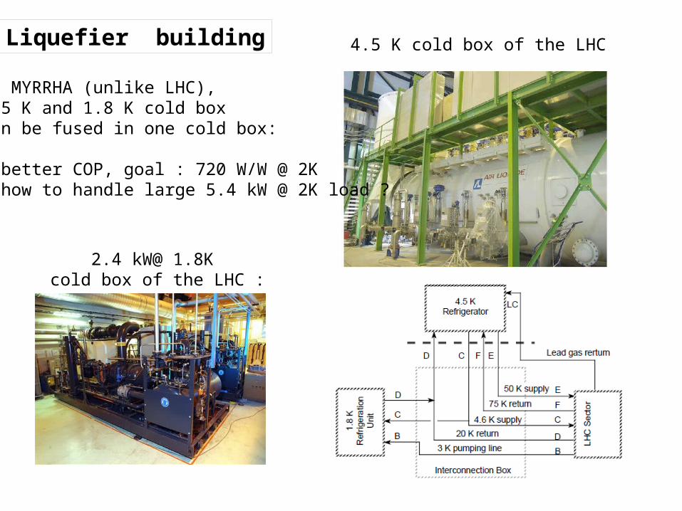
Liquefier building 4.5 K cold box of the LHC
2.4 kW@ 1.8K cold box of the LHC :
In MYRRHA (unlike LHC),4.5 K and 1.8 K cold boxcan be fused in one cold box:
• better COP, goal : 720 W/W @ 2K• how to handle large 5.4 kW @ 2K load ?
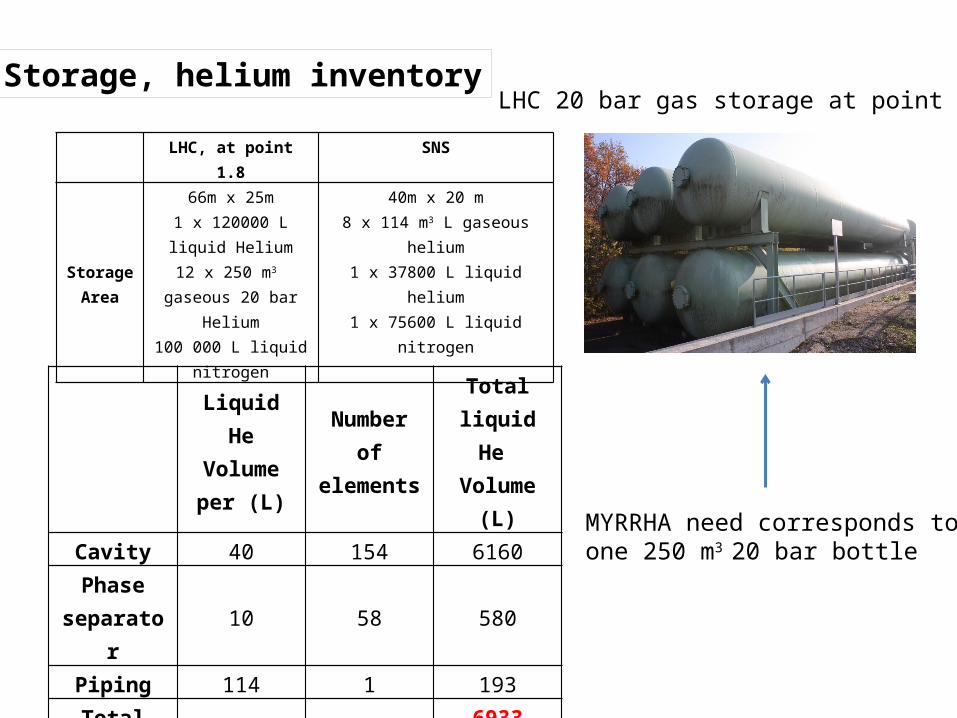
LHC, at point 1.8 SNS
StorageArea
66m x 25m1 x 120000 L liquid
Helium12 x 250 m3 gaseous 20
bar Helium100 000 L liquid
nitrogen
40m x 20 m8 x 114 m3 L gaseous helium
1 x 37800 L liquid helium1 x 75600 L liquid nitrogen
Liquid He Volume per
(L)
Number of elements
Total liquid He Volume
(L)
Cavity 40 154 6160
Phase separator 10 58 580
Piping 114 1 193
Total 6933
Storage, helium inventory
MYRRHA need corresponds toone 250 m3 20 bar bottle
LHC 20 bar gas storage at point 1.8
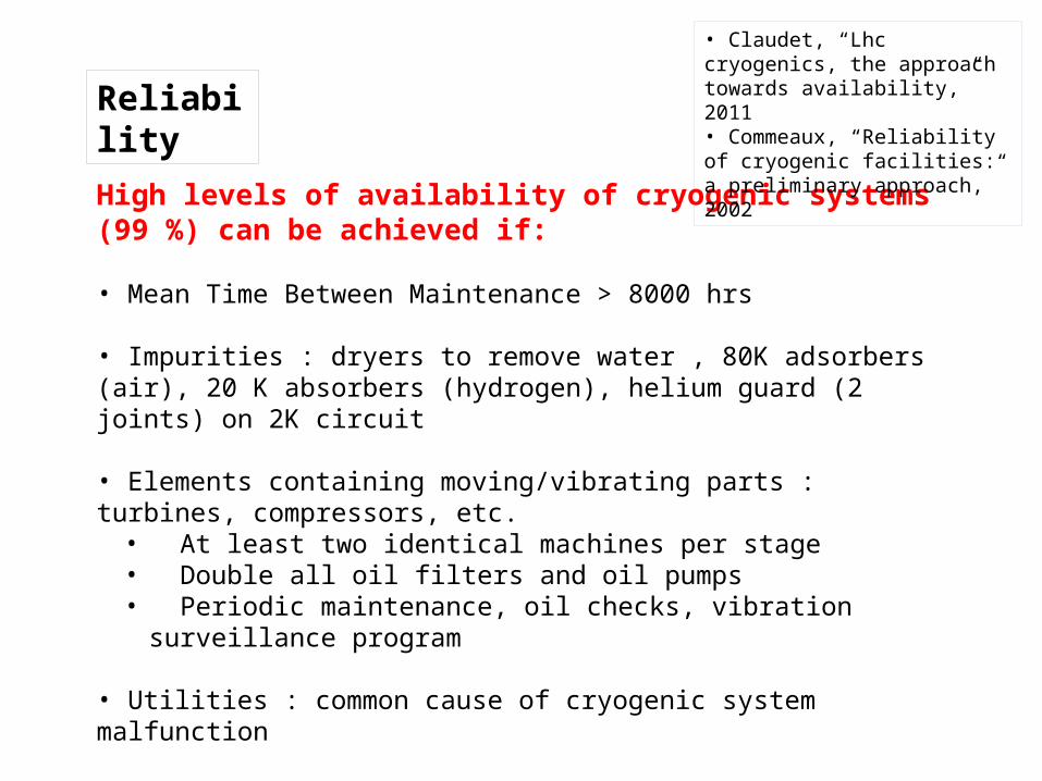
Reliability
High levels of availability of cryogenic systems (99 %) can be achieved if:
• Mean Time Between Maintenance > 8000 hrs
• Impurities : dryers to remove water , 80K adsorbers (air), 20 K absorbers (hydrogen), helium guard (2 joints) on 2K circuit
• Elements containing moving/vibrating parts : turbines, compressors, etc.• At least two identical machines per stage• Double all oil filters and oil pumps • Periodic maintenance, oil checks, vibration surveillance program
• Utilities : common cause of cryogenic system malfunction
• Periodic insulation vacuum control (thermal cycling leaks)
• Easily exchangeable cold compressors
• Claudet, “Lhc cryogenics, the approach towards availability,” 2011• Commeaux, “Reliability of cryogenic facilities: a preliminary approach,” 2002
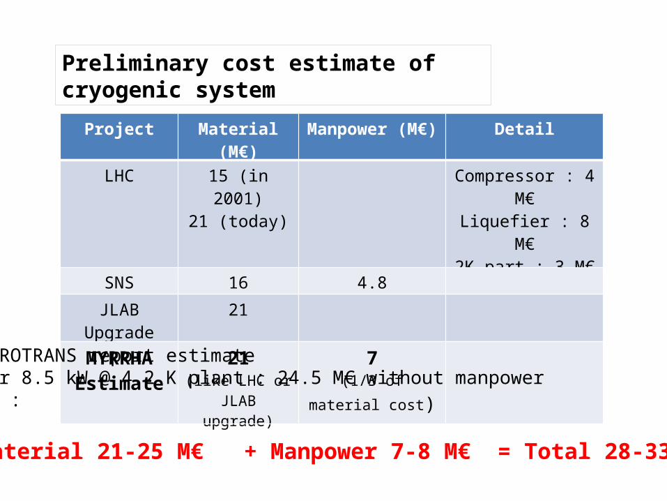
Preliminary cost estimate of cryogenic system
Project Material (M€) Manpower (M€) Detail
LHC 15 (in 2001)21 (today)
Compressor : 4 M€Liquefier : 8 M€2K part : 3 M€
SNS 16 4.8
JLAB Upgrade 21
MYRRHAEstimate
21(like LHC or JLAB
upgrade)
7(1/3 of material cost)
EUROTRANS report estimatefor 8.5 kW @ 4.2 K plant : 24.5 M€ without manpower So :
Material 21-25 M€ + Manpower 7-8 M€ = Total 28-33 M€
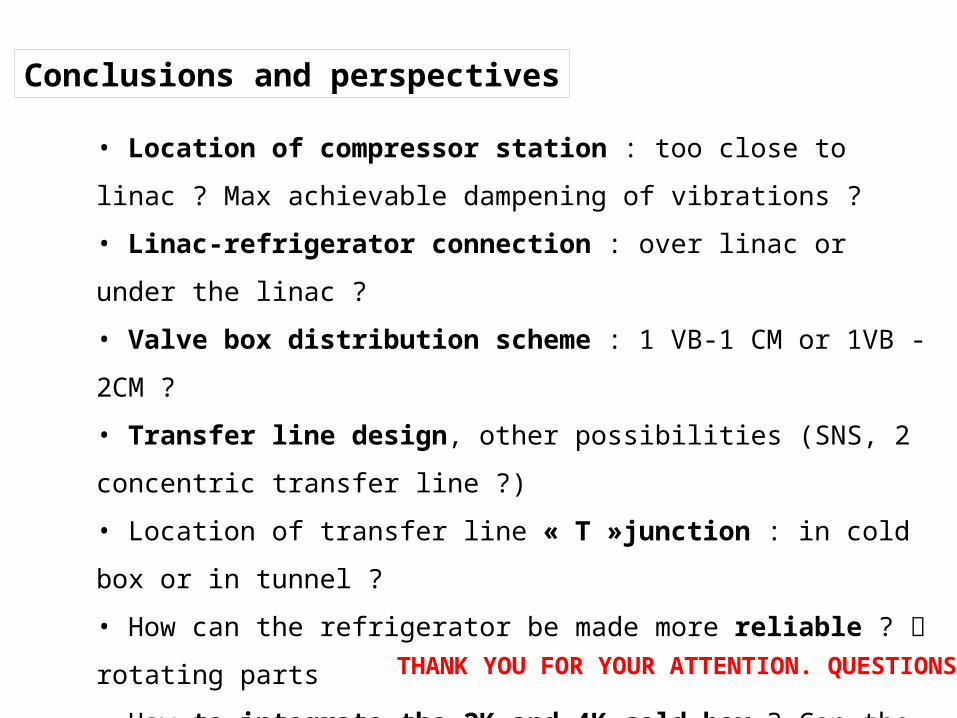
Conclusions and perspectives
• Location of compressor station : too close to linac ? Max achievable
dampening of vibrations ?
• Linac-refrigerator connection : over linac or under the linac ?
• Valve box distribution scheme : 1 VB-1 CM or 1VB -2CM ?
• Transfer line design, other possibilities (SNS, 2 concentric transfer line ?)
• Location of transfer line « T »junction : in cold box or in tunnel ?
• How can the refrigerator be made more reliable ? rotating parts
• How to integrate the 2K and 4K cold box ? Can the 720 W/W be achieved ?
• How to handle the 5.4 kW 2K load of MYRHHA (twice that of the LHC) ?
Upgraded cold compressors ? Cold compressors in parallel ?
• Detailed cost analysis THANK YOU FOR YOUR ATTENTION. QUESTIONS ?