CRRET SESRS F23P 1/6 3 1909 Fluxgate system / Voltage-output … · The user is to perform design,...
8
F23PxxxS05R SERIES Fluxgate system / Voltage-output type ABSOLUTE MAXIMUM RATINGS Parameters Symbol Unit Value Comment Supply voltage Vcc V 7 Primary conductor temperature ― ℃ 110 ESD(HBM: Human Body Model) ― kV 4 C=150pF,R=330Ω ISOLATION CHARACTERISTICS Parameters Symbol Unit Value Comment lnsulation voltage Vd ― AC5000V,for 1minute (Sensing current 0.5mA) Primary ⇔ Secondary lnsulation Resistance R IS ― ≧ 500MΩ(at DC500V) Primary ⇔ Secondary Clearance distance d Cl ― 11.0mm(MIN) Primary ⇔ Secondary Creepage distance d Cp ― 12.7mm(MIN) Primary ⇔ Secondary Case material ― ― UL94 V-0 Comparative Tracking Index;(CTI) CTI V 600 Application example ― ― 600V,CAT Ⅲ,PD2 Reinforced isolation,non uniform field according to EN62477-1:2012 and EN62477-1:2012/ A11 2014,IEC61800-5-1 ― ― 1000V,CAT Ⅲ,PD2 Basic isolation,non uniform field according to EN62477-1:2012 and EN62477-1:2012/A11 2014,IEC61800-5-1 ENVIRONMENTAL AND MECHANICAL CHARACTERISTICS Parameters Symbol Unit Value Comment MIN TYP MAX Ambient operating temperature T A ℃ - 40 + 85 Ambient storage temperature T S ℃ - 40 + 85 Mass m g 13 RoHS CURRENT SENSORS F23P 1/6 3 1909 Introduction Fluxgate system Open loop Closed loop 36
Transcript of CRRET SESRS F23P 1/6 3 1909 Fluxgate system / Voltage-output … · The user is to perform design,...
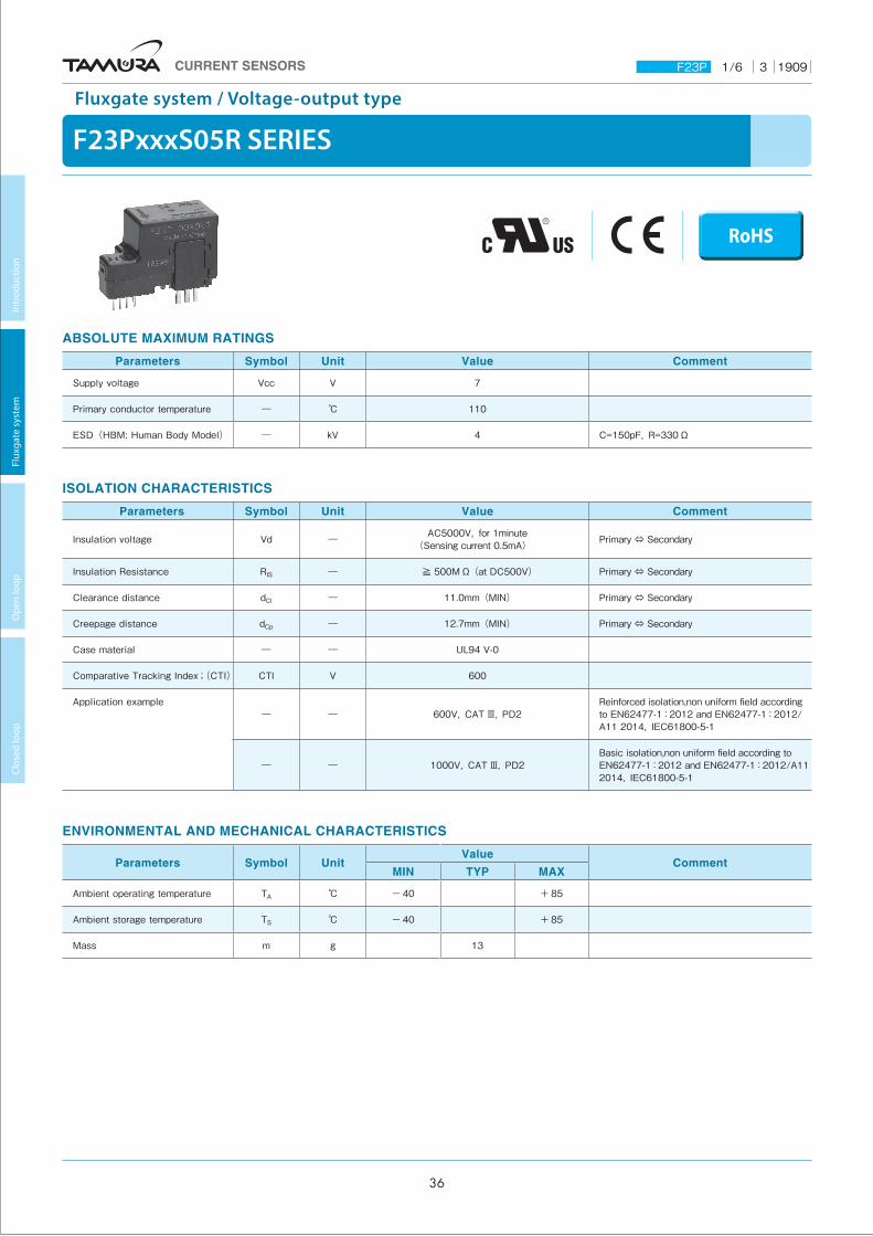
F23PxxxS05R SERIES
Fluxgate system / Voltage-output type
ABSOLUTE MAXIMUM RATINGS
Parameters Symbol Unit Value Comment
Supply voltage Vcc V 7
Primary conductor temperature ― ℃ 110
ESD(HBM: Human Body Model) ― kV 4 C=150pF,R=330Ω
ISOLATION CHARACTERISTICS
Parameters Symbol Unit Value Comment
lnsulation voltage Vd ― AC5000V,for 1minute(Sensing current 0.5mA) Primary ⇔ Secondary
lnsulation Resistance RIS ― ≧ 500MΩ(at DC500V) Primary ⇔ Secondary
Clearance distance dCl ― 11.0mm(MIN) Primary ⇔ Secondary
Creepage distance dCp ― 12.7mm(MIN) Primary ⇔ Secondary
Case material ― ― UL94 V-0
Comparative Tracking Index;(CTI) CTI V 600
Application example― ― 600V,CAT Ⅲ,PD2
Reinforced isolation,non uniform field according to EN62477-1:2012 and EN62477-1:2012/A11 2014,IEC61800-5-1
― ― 1000V,CAT Ⅲ,PD2Basic isolation,non uniform field according to EN62477-1:2012 and EN62477-1:2012/A11 2014,IEC61800-5-1
ENVIRONMENTAL AND MECHANICAL CHARACTERISTICS
Parameters Symbol UnitValue
CommentMIN TYP MAX
Ambient operating temperature TA ℃ - 40 + 85
Ambient storage temperature TS ℃ - 40 + 85
Mass m g 13
RoHS
CURRENT SENSORS F23P 1/6 3 1909
Intr
oduc
tion
Flux
gate
sys
tem
O
pen
loop
Cl
osed
loop
36
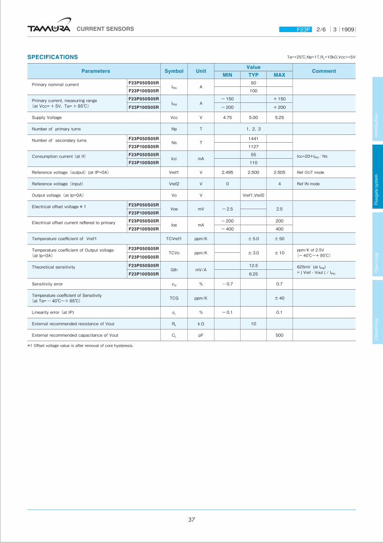
SPECIFICATIONS Ta=+25℃,Np=1T,RL=10kΩ,Vcc=+5V
Parameters Symbol UnitValue
CommentMIN TYP MAX
Primary nominal current F23P050S05RIPN A
50
F23P100S05R 100
Primary current, measuring range(at Vcc= + 5V,Ta= + 85℃)
F23P050S05RIPM A
- 150 + 150
F23P100S05R - 200 + 200
Supply Voltage Vcc V 4.75 5.00 5.25
Number of primary turns Np T 1,2,3
Number of secondary turns F23P050S05RNs T
1441
F23P100S05R 1127
Consumption current (at If) F23P050S05RIcc mA
55 Icc=20+IPN/NsF23P100S05R 110
Reference voltage(output)(at IP=0A) Vref1 V 2.495 2.500 2.505 Ref OUT mode
Reference voltage(input) Vref2 V 0 4 Ref IN mode
Output voltage(at Ip=0A) Vo V Vref1,Vref2
Electrical offset voltage*1 F23P050S05RVoe mV - 2.5 2.5
F23P100S05R
Electrical offset current reffered to primary F23P050S05RIoe mA
- 200 200
F23P100S05R - 400 400
Temperature coefficient of Vref1 TCVref1 ppm/K ± 5.0 ± 50
Temperature coefficient of Output voltage (at Ip=0A)
F23P050S05RTCVo ppm/K ± 3.0 ± 10 ppm/K of 2.5V
(- 40℃〜+ 85℃)F23P100S05R
Theoretical sensitivity F23P050S05RGth mV/A
12.5 625mV (at IPN)= | Vref - Vout | / IPNF23P100S05R 6.25
Sensitivity error εG % - 0.7 0.7
Temperature coefficient of Sensitivity(at Ta= - 40℃〜+ 85℃) TCG ppm/K ± 40
Linearity error(at IP) εL % - 0.1 0.1
External recommended resistance of Vout RL kΩ 10
External recommended capacitance of Vout CL pF 500
*1 Offset voltage value is after removal of core hysteresis.
CURRENT SENSORS F23P 2/6 3 1909
Intr
oduc
tion
Flux
gate
sys
tem
O
pen
loop
Cl
osed
loop
37
STANDARDS
EN62477-1:2012 and EN62477-1:2012/A11 2014,EN(IEC)61800-5-1,UL508(file № E243511),CSA22.2 No.14-13※ Please refer to the another sheet about conditions of UL Recognition.
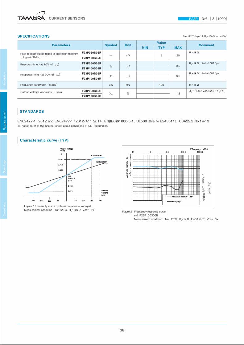
Figure 2: Frequency response curve ex)F23P100S05R Measurement condition Ta=+25℃,RL=1kΩ,Ip=3A×3T,Vcc=+5V
SPECIFICATIONS Ta=+25℃,Np=1T,RL=10kΩ,Vcc=+5V
Parameters Symbol UnitValue
CommentMIN TYP MAX
Peak to peak output ripple at oscillator freqency(f typ=450kHz)
F23P050S05R― mV 5 20
RL=1kΩ
F23P100S05R
Reaction time(at 10% of IPN) F23P050S05Rtra µs 0.5
RL=1kΩ,di/dt=100A/µs
F23P100S05R
Response time(at 90% of IPN) F23P050S05Rtr µs 0.5
RL=1kΩ,di/dt=100A/µs
F23P100S05R
Frequency bandwidth(± 3dB) BW kHz 100 RL=1kΩ
Output Voltage Accuracy(Overall) F23P050S05RXG % 1.2
XG=(100×Voe/625)+εG+εL
F23P100S05R
Characteristic curve (TYP)
Figure 1:Linearity curve(Internal reference voltage) Measurement condition Ta=+25℃,RL=10kΩ,Vcc=+5V
CURRENT SENSORS F23P 3/6 3 1909
Intr
oduc
tion
Flux
gate
sys
tem
O
pen
loop
Cl
osed
loop
38
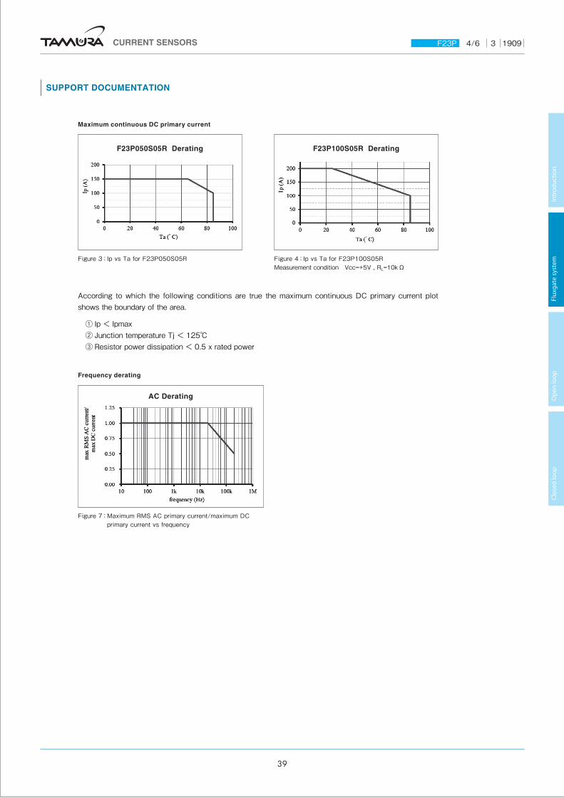
F23P050S05R Derating F23P100S05R Derating
SUPPORT DOCUMENTATION
Maximum continuous DC primary current
Figure 3:Ip vs Ta for F23P050S05R
According to which the following conditions are true the maximum continuous DC primary current plot shows the boundary of the area.
① Ip < Ipmax② Junction temperature Tj < 125℃③ Resistor power dissipation < 0.5 x rated power
Figure 4:Ip vs Ta for F23P100S05RMeasurement condition Vcc=+5V , RL=10kΩ
Frequency derating
Figure 7: Maximum RMS AC primary current/maximum DC primary current vs frequency
AC Derating
CURRENT SENSORS F23P 4/6 3 1909
Intr
oduc
tion
Flux
gate
sys
tem
O
pen
loop
Cl
osed
loop
39
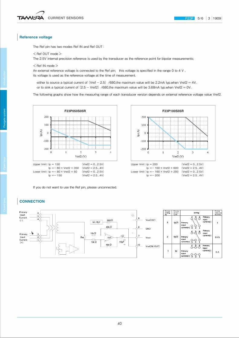
Reference voltage
The Ref pin has two modes Ref IN and Ref OUT:
< Ref OUT mode >The 2.5V internal precision reference is used by the transducer as the reference point for bipolar measurements;
< Ref IN mode >An external reference voltage is connected to the Ref pin; this voltage is specified in the range 0 to 4 V , its voltage is used as the reference voltage at the time of measurement.
-either to source a typical current of (Vref - 2.5)/680,the maximum value will be 2.2mA typ.when Vref2 = 4V.-or to sink a typical current of (2.5 - Vref2)/680,the maximum value will be 3.68mA typ.when Vref2 = 0V.
The following graphs show how the measuring range of each transducer version depends on external reference voltage value Vref2.
F23P050S05R F23P100S05R
Upper limit: Ip = 150 (Vref2 = 0...2.5V) Ip =- 80×Vref2 + 350 (Vref2 = 2.5...4V)
Lower limit: Ip =- 80×Vref2 + 50 (Vref2 = 0...2.5V) Ip =- 150 (Vref2 = 2.5...4V)
Upper limit: Ip = 200 (Vref2 = 0...2.5V) Ip =- 160×Vref2 + 600 (Vref2 = 2.5...4V)
Lower limit: Ip =- 160×Vref2 + 200 (Vref2 = 0...2.5V) Ip =- 200 (Vref2 = 2.5...4V)
If you do not want to use the Ref pin, please unconnected.
CONNECTION
CURRENT SENSORS F23P 5/6 3 1909
Intr
oduc
tion
Flux
gate
sys
tem
O
pen
loop
Cl
osed
loop
40
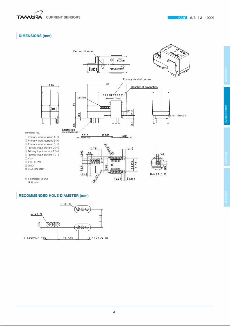
RECOMMENDED HOLE DIAMETER (mm)
DIMENSIONS (mm)
Terminal No.① Primary input current 1(+)② Primary input current 2(+)③ Primary input current 3(+)④Primary input current 3(-)⑤Primary input current 2(-)⑥Primary input current 1(-)⑦ Vout⑧ Vcc(+5V)⑨ GND⑩ Vref(IN/OUT)
※ Tolerance: ± 0.2 Unit: mm
Current direction
CURRENT SENSORS F23P 6/6 3 1909
Intr
oduc
tion
Flux
gate
sys
tem
O
pen
loop
Cl
osed
loop
41
Important Notice
1. The content of this information is subject to change without prior notice for the purpose of improvements, etc. Ensure that you are in possession of the most up-to-date information when using this product.
2. This product is intended to be used in general electronics applications (electric home appliances, business equipment, information equipment, communication terminal equipment, measuring devices, industrial equipment, and so on). This product is neither intended nor warranted for use in following equipment or devices:
Special application (such as for medical devices, transportation equipment, traffic signal control equipment, fire and crime prevention equipment, aeronautics and space devices, nuclear power control, fuel control, in-vehicle equipment, safety devices, and so on) in which extremely high quality and high reliability is required, or if the malfunction or failures of product could be cause loss of human life, bodily injury.
Tamura Corporation shall not be held responsible for any damage incurred by customers or any third party when products are used in special application, unless specifically permitted in this document.
3. Tamura Corporation constantly strives to improve quality and reliability, but malfunction or failures are bound to occur with some probability in current sensor. To ensure that failures do not cause accidents resulting in injury or death, fire accidents, social damage, and so on, users are to thoroughly verify the safety of their designs in devices and/or systems.
4. The operation examples and circuit examples shown in this information are for reference purposes only, and Tamura Corporation disclaims all responsibility for any violations of industrial property rights, intellectual property rights and any other rights owned by Tamura Corporation or third parties that these may entail.
5. The circuit examples and part constants listed in these specifications are provided as reference for the verification of characteristics. The user is to perform design, verification, and judgment under his or her own responsibility, taking into account the various conditions.
6. The products are designed for use in environments where consumer electronics are commonly used. It is not designed for use in special environments such as listed below, and if such use is considered, the user is to perform thorough safety and reliability checks under his/her responsibility.
7. This product is not designed to resist radiation.・ Use in liquids such as water, oil, chemical solutions, or
organic solvents, and use in locations where the product will be exposed to such liquids.
・ Use that involves exposure to direct sunlight, outdoor exposure, or dusty conditions.
・ Use in locations where corrosive gases such as sea winds, Cl2, H2S, NH3, SO2, or NO2, are present. (Some product improves durability)
・ Use in environments with strong static electricity or electromagnetic radiation.
・ Use that involves placing inflammable material next to the product.
・Use of this product either sealed with a resin filling or coated with resin.・Use of water or a water soluble detergent for flux cleaning.・Use in locations where condensation is liable to occur.
8. Do not use or otherwise make available the TAMUTA products or the technology described in this document for any military purposes, including without limitation, for the design, development, use, stockpiling or manufacturing of mass destruction weapons (e.g. nuclear, chemical, or biological weapons or missile technology products). When exporting and re-exporting the products or technology described in this document, you should comply with the applicable export control laws and regulations and follow the procedures required by such laws and regulations including, without limitation, Japan -Foreign Exchange and Foreign Trade Control Law and U.S.- Export Administration Regulations. The TAMURA products and related technology should not be used for or incorporated into any products or systems whose manufacture, use, or sale is prohibited under any applicable domestic or foreign laws or regulations.
9. Please contact your TAMURA sales office for details as to environmental matters such as the RoHS compatibility of Product. Please use TAMURA products in compliance with all applicable laws and regulations that regulate the inclusion or use of controlled substances, including without limitation, the EU RoHS Directive. TAMURA assumes no liability for damages or losses occurring as a result of your noncompliance with applicable laws and regulations.
10. TAMURA assumes no liability for damages or losses incurred by you or third parties as a result of unauthorized use of TAMURA products.
11. This document and any information herein may not be reproduced in whole or in part without prior written permission from TAMURA.
CURRENT SENSORS Notices 1/1 3 1510
9
Application notes
<General Considerations>
1. The sensor uses polar electronic components. When the polarity of the power supply is mistaken, the sensor is damaged.
2. Static electricity or excessive voltage can increase an offset voltage in the Hall element, and cause offset voltage to change. Please exercise care in handling and application.
3. In order to prevent the influence of noise, the use of twisted cable or shielded cable for the output line is recommended
4. If using this device within a magnetic field generated by other devices, the specified accuracy may not be obtainable.
5. Our products (several models are excluded ) are adjusted with the trimming method by the measurement condition
(Load resistance, Power supply voltage) of specification sheets. Therefore, characteristics (Offset, Output, etc.) and its deviation may be changed in different circuit conditions from the measurement condition. All change characteristic items are not indicated on specification sheets.
6. The performance of current sensors with through-hole (aperture) is dependent on the position of the primary conductor. Tamura specifications are based on a primary conductor completely filling the through-hole (aperture) area.
7. The current sensor rated current in DC Amps.8. Please use mating connector with equivalent terminal plating
material to insure proper operation and avoid possibility of ‘galvanic corrosion’.
9. Please do not store in high-temperature and high-humidity storage environment. Please use it after confirming soldering when it is kept for six months or more. (product soldered with substrate)
10. We recommend performing a zero offset adjustment by measuring the offset voltage at startup. In continuously operation for a few months, or at change of ambient temperature or humidity is large, we recommend regularly performing a zero offset adjustment at being idling (it is clear that the current is not apply).
11. The current sensor doesn't have built-in protection circuit (devices and fuses, etc.). As a failure mode of the sensor, there is a short circuit and open state. In the case of a short-circuit state, the abnor-mal temperature rise of the internal parts is assumed, and there is a possibility to smoke and to ignite. If it is used in safety critical circuit blocks, please take appropriate measures by protection devices, protection circuits, etc. For closed loop –type sensors and flux gate (closed loop type) sensors, the consumption current of the secondary power supply varies in proportion to the measurement current.
<Open loop>
1. High frequency primary current may result in excessive heating in iron magnetic core and cause damage to internal circuitry; for high frequency applications select current sensor with ferrite core material.
2. If the measured current exceeds the rated current, magnetic core saturation will occur and the output voltage signal will not be linearly proportional to the measured current.
<Closed Loop>
1. For closed loop current sensors please insure the power supply voltage is balanced, symmetrical, and, applied simultaneously to avoid potential increase in DC offset error.
2. Maximum rated current measurement duration is timedependent. Maximum rated current applied in excess of the time limit can result in damage to internal electronic circuitry; please consult Tamura for assistance.
3. When using a measurement resistor to convert current output to voltage output select a resistor with stable temperature characteristic to insure accuracy of the output voltage.
4. Compensation current supplied to the secondary winding varies in proportion to the measured current based on the conversion ratio. (If/KN; KN = secondary turns) Please insure the PSU has required current capacity to supply compensation current to the secondary winding.
<Flux-Gate>
1. Compensation current supplied to the secondary winding varies in proportion to the measured current. Please insure the PSU has required current capacity to supply compensation current to the secondary winding.
2. There is 450kHz ripple voltage present on the output and reference output voltage signals . An external capacitor maybe added if necessary.
CURRENT SENSORS Appli note 1/1 3 1709
7