CRITICAL CONDITIONS OF PRESSURIZED PIPES … Gajdoˇs L. et al.: Critical Conditions of Pressurized...
12
Engineering MECHANICS, Vol. 20, 2013, No. 5, p. 401–412 401 CRITICAL CONDITIONS OF PRESSURIZED PIPES ’ Lubom´ ır Gajdoˇ s, Martin ˇ Sperl* A simple fracture-mechanics based method is described for assessing a part-through crack in the wall of a pipe subjected to internal pressure of liquid and/or gas. The method utilizes simple approximate expressions for determining the fracture parame- ters K, J, and employs these parameters to determine critical dimensions of a crack on the basis of equality between the J-integral and the J-based fracture toughness of the pipe steel. The crack tip constraint is accounted by the so-called plastic constraint factor C, by which the uniaxial yield stress in the J-integral equation is multiplied. The results of the prediction of the fracture condition are verified by burst tests on test pipes. Keywords : pressurized pipe, J-integral, C factor, critical conditions 1. Introduction In thin-walled gas pipelines it should be expected that defects can occur. Under certain conditions, the defects can grow and they will gradually shorten the residual life of gas pipelines. Using fracture mechanics we can assess the threat that such defects can pose to the pipeline wall taking into account whether a brittle, quasi-brittle or ductile material is involved. A model description of crack-containing systems, based on the stress inten- sity factor (SIF), K, can be used for brittle and quasi-brittle fracture, and in addition for subcritical fatigue growth, corrosion fatigue and stress corrosion [1], [2]. In these cases, the surface crack is usually located in the field of one of the membrane tensile stress components or in the field of bending stress, or in a combination of these two stresses. In comparison with the dimensions of the crack and the cross section of the pipeline the extent of the plastic zone at the crack tip is small. If the gas pipeline is made of a high toughness mate- rial, the plastic strains become extensive before the crack reaches instability. Hence, some elasto-plastic fracture mechanics methods, such as J -integral, crack opening displacement, the two-criterion method or some other procedure, should be employed to assess the frac- ture condition of the pipeline [3], [4]. Because the method of determination of burst pressure of thin-walled pressure vessels utilizes simple approximate expressions for determining the fracture parameters K, J , a brief background of some fracture-mechanics formulae will be made first. * Ing. ’ L. Gajdoˇ s, CSc., Ing. M. ˇ Sperl, Ph.D., Institute of Theoretical and Applied Mechanics AS CR, v. v. i., Proseck´ a 809/76, 190 00 Praha 9, CZ
Transcript of CRITICAL CONDITIONS OF PRESSURIZED PIPES … Gajdoˇs L. et al.: Critical Conditions of Pressurized...

Engineering MECHANICS, Vol. 20, 2013, No. 5, p. 401–412 401
CRITICAL CONDITIONS OF PRESSURIZED PIPES
’Lubomır Gajdos, Martin Sperl*
A simple fracture-mechanics based method is described for assessing a part-throughcrack in the wall of a pipe subjected to internal pressure of liquid and/or gas. Themethod utilizes simple approximate expressions for determining the fracture parame-ters K, J, and employs these parameters to determine critical dimensions of a crack onthe basis of equality between the J-integral and the J-based fracture toughness of thepipe steel. The crack tip constraint is accounted by the so-called plastic constraintfactor C, by which the uniaxial yield stress in the J-integral equation is multiplied.The results of the prediction of the fracture condition are verified by burst tests ontest pipes.
Keywords : pressurized pipe, J-integral, C factor, critical conditions
1. Introduction
In thin-walled gas pipelines it should be expected that defects can occur. Under certainconditions, the defects can grow and they will gradually shorten the residual life of gaspipelines. Using fracture mechanics we can assess the threat that such defects can poseto the pipeline wall taking into account whether a brittle, quasi-brittle or ductile materialis involved. A model description of crack-containing systems, based on the stress inten-sity factor (SIF), K, can be used for brittle and quasi-brittle fracture, and in addition forsubcritical fatigue growth, corrosion fatigue and stress corrosion [1], [2]. In these cases, thesurface crack is usually located in the field of one of the membrane tensile stress componentsor in the field of bending stress, or in a combination of these two stresses. In comparisonwith the dimensions of the crack and the cross section of the pipeline the extent of theplastic zone at the crack tip is small. If the gas pipeline is made of a high toughness mate-rial, the plastic strains become extensive before the crack reaches instability. Hence, someelasto-plastic fracture mechanics methods, such as J-integral, crack opening displacement,the two-criterion method or some other procedure, should be employed to assess the frac-ture condition of the pipeline [3], [4]. Because the method of determination of burst pressureof thin-walled pressure vessels utilizes simple approximate expressions for determining thefracture parameters K, J , a brief background of some fracture-mechanics formulae will bemade first.
* Ing. ’L.Gajdos, CSc., Ing. M. Sperl, Ph.D., Institute of Theoretical and Applied Mechanics AS CR, v. v. i.,Prosecka 809/76, 190 00 Praha 9, CZ
402 Gajdos ’L. et al.: Critical Conditions of Pressurized Pipes
2. Fracture-mechanics formulae used
SIF for an axial through crack
The stress intensity factor can be determined by equation (1)
KI = MT σϕ
√π c (1)
where σϕ = p D/(2 t) is the hoop stress, and MT is the Folias correction factor, takingaccount of curvature of a pipe.
One of the most widely used expressions to determine the Folias factor is the following [5] :
MT =
√1 + 1.255
c2
R t− 0.0135
c4
R2 t2(2)
where R is the mean radius of the pipe, and t is the pipe wall thickness.
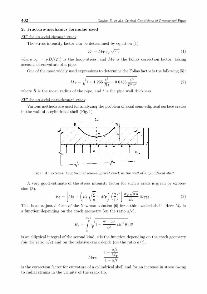
SIF for an axial part-through crack
Various methods are used for analyzing the problem of axial semi-elliptical surface cracksin the wall of a cylindrical shell (Fig. 1).
Fig.1: An external longitudinal semi-elliptical crack in the wall of a cylindrical shell
A very good estimate of the stress intensity factor for such a crack is given by expres-sion (3).
KI =[MF +
(Ek
√c
a− MF
)(a
t
)s]
σϕ√
π a
EkMTM . (3)
This is an adjusted form of the Newman solution [6] for a thin- walled shell. Here MF isa function depending on the crack geometry (on the ratio a/c),
Ek =
π/2∫0
√1 − c2 − a2
c2sin2 θ dθ
is an elliptical integral of the second kind, s is the function depending on the crack geometry(on the ratio a/c) and on the relative crack depth (on the ratio a/t),
MTM =1 − a/t
MT
1 − a/t
is the correction factor for curvature of a cylindrical shell and for an increase in stress owingto radial strains in the vicinity of the crack tip.
Engineering MECHANICS 403
Functions MF and p differ in form for the lowest point of the crack tip (point A in Fig. 1)and for the crack mouth on the surface of the cylindrical shell (point B in Fig. 1).
The next fracture-mechanics parameter we need for determination of the burst pressureof a pipeline is J integral. The actual magnitude of this quantity will be compared to itscritical value – the fracture toughness. From this comparison a magnitude of the burstpressure will result.
3. Engineering methods for determination of J integral
3.1. FC method
This method was proposed in Addendum A16 of the French nuclear code [7] as the Js
method. It stems from the second option of describing the transition state between ideallyelastic and fully plastic behaviour of material, that is to say from the function f2(Lr) of theR6 method [8]. This function takes the form :
f2(Lr) =(
E εref
Lr Re+
L3r Re
2 E εref
)− 12
(4)
where Lr = σ/σL (σ – applied stress, σL – stress at the limit load), Re is the yield stress,E is Young ’ts modulus εref is the reference strain corresponding to the reference (nominal)stress σref.
If we identify function f2(Lr) with function f3(Lr) = (J/Je)−1/2 and express Lr as σref/Re
and elastic J integral Je as K2/E′, where E′ = E for plane stress state and E′ = E/(1−ν2)for plane strain state, we have :
J =K2
E′
(E εref
σref+
σ3ref
2 E R2e εref
). (5)
The stress σref in the above equation is a nominal stress – i.e. a stress acting in the planewhere the crack occurs. Taking into consideration the description of the stress-strain depen-dence by the Ramberg-Osgood relation (6) and adjusting Eq. (5) we obtain the J-integralin the form (7).
ε
ε0=
σ
σ0+ α
(σ
σ0
)n
(6)
in which the stress σ0 can be substituted by the yield stress Re, ε0 = σ0/E (α, n – materialconstants)
J =K2
E′
[A +
0.5A
(σ
σ0
)2]
(7)
where
A = 1 + α
(σ
σ0
)n−1
. (8)
As the pipeline is a body of finite dimensions, stress σ in Eqs. (7) and (8) is a nominalstress – i.e. a stress acting in the plane where the crack occurs. Referring to the R6 method [8]this stress for the pipe containing longitudinal part-through thickness crack may be writtenas :
σ =σϕ
1 − π a c
2 t (t + 2 c)
. (9)
404 Gajdos ’L. et al.: Critical Conditions of Pressurized Pipes
In eq. (9) σϕ = p D/(2 t) is the hoop stress and the meaning of the symbols a, c, and t isclear from Fig. 2.
3.2. GS method
The GS method was derived by Gajdos and Srnec [9] on the basis of the limit transitionof J-integral, formally expressed for a semi-circular notch, to a crack, with the variation ofthe strain energy density along the notch circumference being approximated by the thirdpower of the cosine function of the polar angle. If the stress-strain dependence is furtherexpressed by the Ramberg-Osgood relation (6) with ε0 = σ0/E, (α, n – material constants)it can be arrived at Eq. (10)
J =K2
E′
[1 +
2 α n
n + 1
(σ
σ0
)n−1]
. (10)
where σ is the nominal stress in the reduced cross-section of a body. For a pipe containinglongitudinal part-through thickness crack it may be determined by the relation (9).
4. Accounting the constraint
The crack tip constraint is accounted here by a simple procedure based on the so-calledplastic constraint factor on yielding, C. This factor is given by the ratio of the stress σ1
needed to obtain plastic macrostrains under constraint conditions to the yield stress at a ho-mogeneous uniaxial state of stress [10]. The C factor can be expressed by the relation (11)
C =σ1
σHMH(11)
where σHMH, the Huber-Mises-Hencky stress, is put equal to the yield stress.
Let us now consider the state of stress at the crack tip in a thick-walled body, wherethe stress perpendicular to the crack plane, σ1, and the stress in the direction of the crack,σ2, are equal, and the stress in the direction of the thickness of the body, σ3, is governedby the expression σ3 = ν (σ1 + σ2). Then, based on the HMH criterion and assumedelastic conditions (ν ∼= 0.33), the plastic constraint factor C ≈ 3. If the stress in thethickness direction, σ3, falls within 2 ν σ1 and zero (thin-walled body), the value of theplastic constraint factor will range between C = 1 and C = 3. These data can be usedto assess fracture conditions in gas pipelines with surface part- through cracks, employinga C-factor which has to be experimentally determined. After determination of the C factorthe value of C σ0 would be used instead of the yield stress σ0 in relations for the calculationof J-integral.
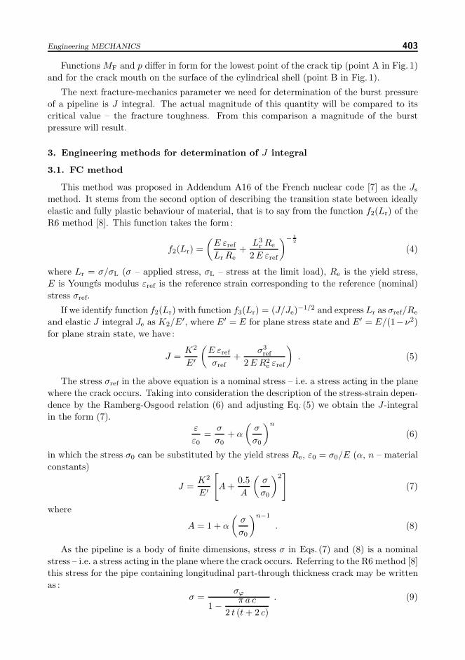
The C factor was experimentally investigated at the Institute of Theoretical and AppliedMechanics of the Academy of Science of the Czech Republic in the framework of a broaderproject concerned with research of the reliability and operational safety of high pressure gaspipelines. Fracture conditions were investigated on five pipe bodies, made of steels X52, X65a X70, with cycling-induced cracks. Data on the pipe bodies used, cracks in the walls, andmechanical and fracture-mechanical material properties of the bodies are given in Table 1.
The individual rows in the table show the following data (top to bottom) : body diame-ter D, body wall thickness t, half-length of longitudinal part-through crack c, crack depth a,
Engineering MECHANICS 405
Material X 52 X 65 X 65 X 70 X 70
D (mm) 820 820 820 1018 1018
t (mm) 10.2 10.7 10.6 11.7 11.7
c (mm) 50 100 100 127 115
a (mm) 7.0 7.7 7.0 6.7 7.1
a/t 0.686 0.720 0.660 0.573 0.607
a/c 0.14 0.077 0.07 0.053 0.062
p (MPa) 8.05 9.71 9.86 9.86 9.55
p/p0.2 1.034 0.750 0.769 0.800 0.775
σ0 (MPa) 313 496 496 536 536
α 2.40 5.34 5.34 5.92 5.92
n 6.25 8.45 8.45 9.62 9.62
C 2.1 2.4 2.4 2.0 2.07
Jcr (N/mm) 487 432 432 439 439
T/σ0 0.672 0.575 0.544 0.606 0.611
Q 0.667 0.591 0.546 0.648 0.651
Tab.1: Summary of data concerning the assessmentof the fracture behaviour of pipe bodies
relative crack depth a/t, aspect ratio a/c of a semi-elliptical crack, fracture pressure p, ratioof fracture pressure p and pressure p0.2 corresponding to the hoop stress at the yield stress,yield stress in the circumferential direction of the body σ0, Ramberg-Osgood constant α,Ramberg-Osgood exponent n, plastic constraint factor C, J-integral critical value Jcr, de-termined as Jm (corresponding to attaining the maximum force at the ‘force – force pointdisplacement’ curve), T -stress to yield stress ratio T/σ0, and Q parameter. Values of σ0, α
and n were derived from tensile tests and the values of Jcr from fracture tests run on CTspecimens. Values of the fracture pressure p were read at the moment the ligament under thecrack in the pipe body ruptured. Values of the plastic constraint factor on yielding, C, weredetermined on the basis of J-integral in such a way that agreement was reached between thepredicted and experimentally established fracture parameters for the given crack and frac-ture toughness of the material. The J-integral value was calculated from the GS method [9]on the one hand and the French nuclear code [7] on the other hand.
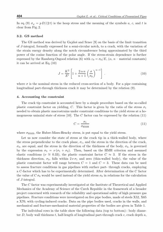
It should be noted that in determining the C factor the critical value of J-integralestablished on CT specimens was considered-namely Jcr = 439N/mm for steel X70,Jcr = 432N/mm for steel X65 and Jcr = 487N/mm for steel X52. It was found out bya computational analysis of CT specimens, employed to construct the R curve, that theQ parameter for these specimens had been Q = 0.267 . A comparison of this with theQ parameter for pipe bodies (Q ≈ −0.55 ÷ −0.65) reveals that the constraint in the CTspecimens was much higher. This implies that the real fracture toughness – i.e. the criticalvalue of J-integral, Jcr – was higher in the pipe bodies. The real C factor for a crackedpipe body is lower, so that the J-a curve for a pipe body is steeper than that for CT spe-cimens with a greater C factor [11]. Due to this, the J integral for the axial part-throughcrack reaches the corresponding higher fracture toughness (for a lower constraint) for thesame crack depth as the J integral with a higher C factor reaches lower fracture toughness(determined on CT specimens). The situation is illustrated in Fig. 2.
Normalized T -stress values in Table 1 were obtained by the use of the plane solution – i.e.solution for an infinite length of a crack oriented longitudinally along the pipe. The problem
406 Gajdos ’L. et al.: Critical Conditions of Pressurized Pipes
Fig.2: Schematic J-a dependence for (i) a CT specimen,and (ii) a pipe with an axial part-through crack
was solved in the Institute of Physics of Materials, Brno, by the finite elements method.The solution included two steps.: (i) a corresponding FEM network was established andcorresponding boundary conditions were formulated for each crack depth, (ii) magnitudes ofthe stress intensity factor and the T -stress were calculated for each FEM network by meansof the FEM system CRACK2D with hybrid crack elements. Values of the Q parameter werederived from Q-T/σ0 curves, obtained by O’Dowd and Shih [12] by modified boundary layeranalysis for different values of the strain coefficient (Ramberg-Osgood exponent, n). Strictlyspeaking, the Q parameter values from Table 1 do not correspond accurately to values forthe examined cracks, because T -stresses were not computed for real semi-elliptical cracks,but for cracks spreading along the entire length of pipe body (a/c ≈ 0). Nevertheless, withregard to the fact that the ratio of the depth to the surface half-length of examined cracks(a/c) was close to zero (a/c = 0.053÷0.14), we can assume that the differences between realvalues of the Q parameter and the values listed in Table 1 will be small. Relations betweenthe C and the Q parameter will be discussed later.
5. Experimental verification of the approach
The engineering approach for determination of critical parameters of pressurized crackedpipes was verified by burst tests. These tests were realized in the institute SVUM Praha.For burst tests of pipe bodies it is usually sufficient that the length of the pipe betweenthe welds of dished bottoms is at least 3.5D. Such a length permits placing a numberof starting cuts axially along the length of the body. The cuts are made to initiate crackgrowth when the body is subsequently pressurized by a fluctuating pressure of water. Theycan be made in several ways, of which one uses a thin grinding wheel. The smallest realfunctional thickness of such a wheel is about 1.2mm and the corresponding width of thecuts made with it is approximately 1.5mm. Depending on the type of pipes of which gaspipelines are built (seamless, spirally welded, longitudinally welded) the starting cuts canbe provided in the base material, transition region or the weld metal, their orientation beingaxial, circumferential or along the spiral weld. The depth of an initiated fatigue crack mustbe at least 0.5mm along the whole perimeter of the cut tip so that the cut with the initiatedcrack at its tip can be considered as a crack after the pipe body has been subjected tocycling. This value follows from work of Smith and Miller [13].
Engineering MECHANICS 407
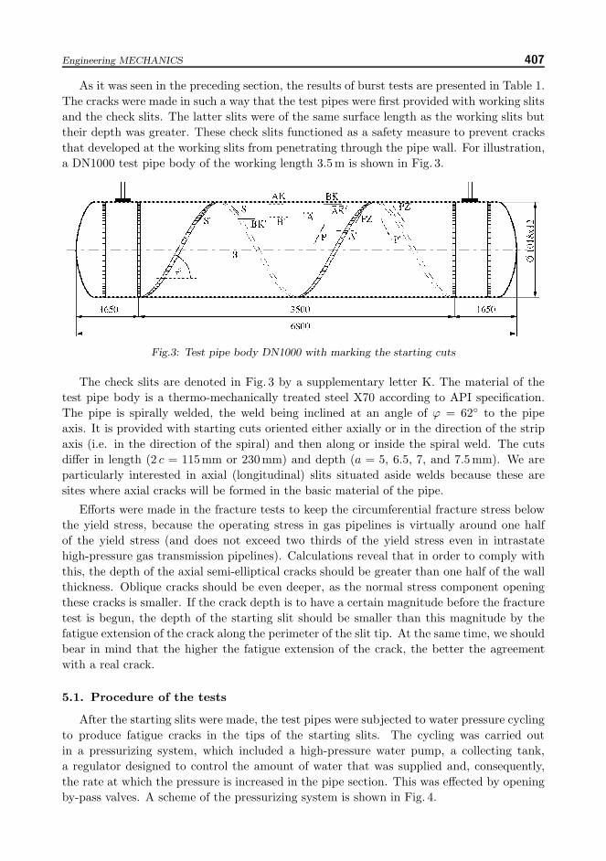
As it was seen in the preceding section, the results of burst tests are presented in Table 1.The cracks were made in such a way that the test pipes were first provided with working slitsand the check slits. The latter slits were of the same surface length as the working slits buttheir depth was greater. These check slits functioned as a safety measure to prevent cracksthat developed at the working slits from penetrating through the pipe wall. For illustration,a DN1000 test pipe body of the working length 3.5m is shown in Fig. 3.
Fig.3: Test pipe body DN1000 with marking the starting cuts
The check slits are denoted in Fig. 3 by a supplementary letter K. The material of thetest pipe body is a thermo-mechanically treated steel X70 according to API specification.The pipe is spirally welded, the weld being inclined at an angle of ϕ = 62◦ to the pipeaxis. It is provided with starting cuts oriented either axially or in the direction of the stripaxis (i.e. in the direction of the spiral) and then along or inside the spiral weld. The cutsdiffer in length (2 c = 115mm or 230mm) and depth (a = 5, 6.5, 7, and 7.5mm). We areparticularly interested in axial (longitudinal) slits situated aside welds because these aresites where axial cracks will be formed in the basic material of the pipe.
Efforts were made in the fracture tests to keep the circumferential fracture stress belowthe yield stress, because the operating stress in gas pipelines is virtually around one halfof the yield stress (and does not exceed two thirds of the yield stress even in intrastatehigh-pressure gas transmission pipelines). Calculations reveal that in order to comply withthis, the depth of the axial semi-elliptical cracks should be greater than one half of the wallthickness. Oblique cracks should be even deeper, as the normal stress component openingthese cracks is smaller. If the crack depth is to have a certain magnitude before the fracturetest is begun, the depth of the starting slit should be smaller than this magnitude by thefatigue extension of the crack along the perimeter of the slit tip. At the same time, we shouldbear in mind that the higher the fatigue extension of the crack, the better the agreementwith a real crack.
5.1. Procedure of the tests
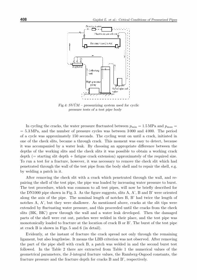
After the starting slits were made, the test pipes were subjected to water pressure cyclingto produce fatigue cracks in the tips of the starting slits. The cycling was carried outin a pressurizing system, which included a high-pressure water pump, a collecting tank,a regulator designed to control the amount of water that was supplied and, consequently,the rate at which the pressure is increased in the pipe section. This was effected by openingby-pass valves. A scheme of the pressurizing system is shown in Fig. 4.
408 Gajdos ’L. et al.: Critical Conditions of Pressurized Pipes
Fig.4: SVUM – pressurizing system used for cyclicpressure tests of a test pipe body
In cycling the cracks, the water pressure fluctuated between pmin = 1.5MPa and pmax == 5.3MPa, and the number of pressure cycles was between 3 000 and 4 000. The periodof a cycle was approximately 150 seconds. The cycling went on until a crack, initiated inone of the check slits, became a through crack. This moment was easy to detect, becauseit was accompanied by a water leak. By choosing an appropriate difference between thedepths of the working slits and the check slits it was possible to obtain a working crackdepth (= starting slit depth + fatigue crack extension) approximately of the required size.To run a test for a fracture, however, it was necessary to remove the check slit which hadpenetrated through the wall of the test pipe from the body shell and to repair the shell, e.g.by welding a patch in it.
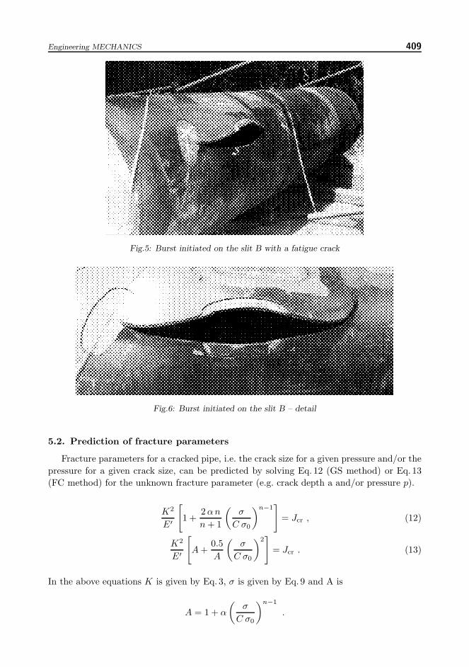
After removing the check slit with a crack which penetrated through the wall, and re-pairing the shell of the test pipe, the pipe was loaded by increasing water pressure to burst.The test procedure, which was common to all test pipes, will now be briefly described forthe DN1000 pipe shown in Fig. 3. As the figure suggests, slits A, A’, B and B’ were orientedalong the axis of the pipe. The nominal length of notches B, B’ had twice the length ofnotches A, A’, but they were shallower. As mentioned above, cracks at the slit tips wereextended by fluctuating water pressure, and this proceeded until the cracks from the checkslits (BK, BK’) grew through the wall and a water leak developed. Then the damagedparts of the shell were cut out, patches were welded in their place, and the test pipe wasmonotonically loaded to fracture at the location of crack B or B’. The burst of the test pipeat crack B is shown in Figs. 5 and 6 (in detail).
Evidently, at the instant of fracture the crack spread not only through the remainingligament, but also lengthwise. It means the LBB criterion was not observed. After removingthe part of the pipe shell with crack B, a patch was welded in and the second burst testfollowed. In the Table 2 there are extracted from Table 1 the numerical values of thegeometrical parameters, the J-integral fracture values, the Ramberg-Osgood constants, thefracture pressure and the fracture depth for cracks B and B’, respectively.
Engineering MECHANICS 409
Fig.5: Burst initiated on the slit B with a fatigue crack
Fig.6: Burst initiated on the slit B – detail
5.2. Prediction of fracture parameters
Fracture parameters for a cracked pipe, i.e. the crack size for a given pressure and/or thepressure for a given crack size, can be predicted by solving Eq. 12 (GS method) or Eq. 13(FC method) for the unknown fracture parameter (e.g. crack depth a and/or pressure p).
K2
E′
[1 +
2 α n
n + 1
(σ
C σ0
)n−1]
= Jcr , (12)
K2
E′
[A +
0.5A
(σ
C σ0
)2]
= Jcr . (13)
In the above equations K is given by Eq. 3, σ is given by Eq. 9 and A is
A = 1 + α
(σ
C σ0
)n−1
.
410 Gajdos ’L. et al.: Critical Conditions of Pressurized Pipes
Jcr in Eq. 12 and 13 is the critical magnitude of the J integral – the fracture toughness– taken here as the value Jm and α, n, σ0 are the Ramberg-Osgood parameters of the steelin the hoop direction.
As it can be deduced from Table 1 the crack B fractured first, namely when the waterpressure reached the value p = 9.55MPa. The damaged part of the pipe shell was thencut out, the fracture surfaces were released to enable their fractographic examination. Themissing part of the shell was replaced by welding a patch on it. In the second burst testthe crack B’ fractured at the pressure p = 9.86MPa. After cutting out the damaged part ofthe pipe shell the fracture surfaces were released and were then subjected to fractographicexamination. The results are digestedly presented in Table 2.
Characteristics Crack B Crack B’
Crack dimensions
half-length, c (mm) 115 127
depth in fracture, af (mm) 7.1 6.7
Ramberg-Osgood parameters
α / n / σ0 (MPa) 5.92 / 9.62 / 536 5.92 / 9.62 / 536
Fracture toughness
Jcr = Jm (N/mm) 439 439
Fracture pressure
pf (MPa) 9.55 9.86
Tab.2: Some characteristics referring to crack B and crack B’
It is seen from here that the crack depth at fracture was 7.1mm for crack B and 6.7mmfor crack B’. These values are also shown in the last two columns of Table 1.
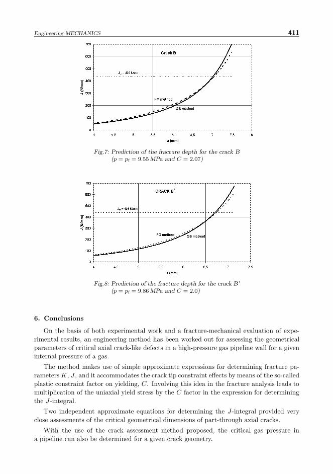
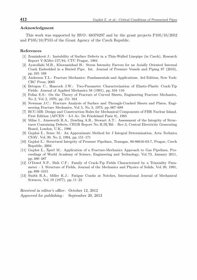
Now let us predict the fracture conditions according to engineering approaches, andcompare the prediction results with real fracture parameter values (pressure, crack depth).As it was already stated the procedure for verifying the predictive engineering methodsinvolves determining either the fracture stress for a given (fracture) crack depth or thefracture crack depth for a given (fracture) pressure. To illustrate this, we select the lattercase – i.e. determining the fracture depth of a crack for a given (fracture) pressure. We willnot use directly Eqs. 12 and 13 but general dependences of the J integral (given by the left-hand side of Eqs. 12 and 13) on the crack depth a. Fig. 7 shows the J-integral vs. crack Bdepth dependences, as determined by the FC and GS predictions for the fracture hoopstress corresponding to the measured fracture pressure. When using appropriate equationsto determine J integrals, the following parameters were used : D = 1018mm; t = 11.7mm;p = pf = 9.55MPa; c = 115mm; α = 5.92; n = 9.62; σ0 = 2.07×536 = 1110MPa (i.e.C = 2.07). Similarly, Fig. 8 shows J-a dependences for crack B’.
Data in Table 2 as well as Figs. 7 and 8 illustrate that experimental results obtained arefully in accord with fracture mechanical principles, i.e. that for a deeper crack (B) the burstpressure is smaller than that for a shallower crack (B’) while neglecting a small differencein the surface length of both cracks. By identifying predicted values of pressure p and crackdepth a at fracture with experimentally determined values it was possible to ascertain themagnitude of the plastic constraint factor on yielding C to be around 2 with a tendency tobe higher for a deeper crack.
Engineering MECHANICS 411
Fig.7: Prediction of the fracture depth for the crack B(p = pf = 9.55 MPa and C = 2.07)
Fig.8: Prediction of the fracture depth for the crack B’(p = pf = 9.86 MPa and C = 2.0)
6. Conclusions
On the basis of both experimental work and a fracture-mechanical evaluation of expe-rimental results, an engineering method has been worked out for assessing the geometricalparameters of critical axial crack-like defects in a high-pressure gas pipeline wall for a giveninternal pressure of a gas.
The method makes use of simple approximate expressions for determining fracture pa-rameters K, J , and it accommodates the crack tip constraint effects by means of the so-calledplastic constraint factor on yielding, C. Involving this idea in the fracture analysis leads tomultiplication of the uniaxial yield stress by the C factor in the expression for determiningthe J-integral.
Two independent approximate equations for determining the J-integral provided veryclose assessments of the critical geometrical dimensions of part-through axial cracks.
With the use of the crack assessment method proposed, the critical gas pressure ina pipeline can also be determined for a given crack geometry.
412 Gajdos ’L. et al.: Critical Conditions of Pressurized Pipes
Acknowledgment
This work was supported by RVO : 68378297 and by the grant projects P105/10/2052and P105/10/P555 of the Grant Agency of the Czech Republic.
References[1] Zemankova J.: Instability of Surface Defects in a Thin-Walled Linepipe (in Czech), Research
Report V-KMtr-157/84, CTU Prague, 1984[2] Ayatollahi M.R., Khoramishad H.: Stress Intensity Factors for an Axially Oriented Internal
Crack Embedded in a Buried Pipe. Int. Journal of Pressure Vessels and Piping 87 (2010),pp. 165–169
[3] Anderson T.L.: Fracture Mechanics: Fundamentals and Applications. 3rd Edition, New York:CRC Press; 2005
[4] Betegon C., Hancock J.W.: Two-Parameter Characterization of Elastic-Plastic Crack-TipFields. Journal of Applied Mechanics 58 (1991), pp. 104–110
[5] Folias E.S.: On the Theory of Fracture of Curved Sheets, Engineering Fracture Mechanics,No. 2, Vol. 2, 1970, pp. 151–164
[6] Newman J.C.: Fracture Analysis of Surface and Through-Cracked Sheets and Plates, Engi-neering Fracture Mechanics, Vol. 5, No. 3, 1973, pp. 667–689
[7] RCC-MR: Design and Construction Rules for Mechanical Components of FBR Nuclear Island.First Edition (AFCEN – 3-5 Av. De Friedeland Paris 8), 1985
[8] Milne I., Ainsworth R.A., Dowling A.R., Stewart A.T.: Assessment of the Integrity of Struc-tures Containing Defects, CEGB Report No.R/H/R6 – Rev.3, Central Electricity GeneratingBoard, London, U.K., 1986
[9] Gajdos ’L., Srnec M.: An Approximate Method for J Integral Determination, Acta TechnicaCSAV, Vol. 39, No. 2, 1994, pp. 151–171
[10] Gajdos ’L.: Structural Integrity of Pressure Pipelines, Transgas, 80-86616-03-7, Prague, CzechRepublic, 2004
[11] Gajdos ’L., Sperl M.: Application of a Fracture-Mechanics Approach to Gas Pipelines, Pro-ceedings of World Academy of Science, Engineering and Technology, Vol. 73, January 2011,pp. 480–487
[12] O’Dowd N.P., Shih C.F.: Family of Crack-Tip Fields Characterized by a Triaxiality Para-meter – I. Structure of Fields, Journal of the Mechanics and Physics of Solids, Vol. 39, 1991,pp. 898–1015
[13] Smith R.A., Miller K.J.: Fatigue Cracks at Notches, International Journal of MechanicalSciences, Vol. 19 (1977), pp. 11–22
Received in editor’s office : October 12, 2012Approved for publishing : September 20, 2013