Crack tip enrichment in the XFEM method using a cut-off...
19
INTERNATIONAL JOURNAL FOR NUMERICAL METHODS IN ENGINEERING Int. J. Numer. Meth. Engng 2006; 00:1–15 Prepared using nmeauth.cls [Version: 2002/09/18 v2.02] Crack tip enrichment in the XFEM method using a cut-off function Elie Chahine 1, ∗ Patrick Laborde 2 , Yves Renard 3 1 Institut de Math´ ematiques, UMR CNRS 5215, GMM INSA Toulouse, Complexe scientifique de Rangueil, 31077 Toulouse Cedex 4, France, [email protected] 2 Institut de Math´ ematiques, UMR CNRS 5215, UPS Toulouse 3, 118 route de Narbonne, 31062 Toulouse cedex 4, France, [email protected] 3 Institut Camille Jordan, CNRS UMR 5208, INSA de Lyon, Universit´ e de Lyon, 20 rue Albert Einstein, 69621 Villeurbanne Cedex, France, [email protected] SUMMARY We consider a variant of the eXtended Finite Element Method (XFEM) in which a cut-off function is used to localize the singular enrichment surface. The goal of this variant is to obtain numerically an optimal convergence rate while reducing the computational cost of the classical XFEM with a fixed enrichment area. We give a mathematical result of quasi-optimal error estimate. One of the key points of the paper is to prove the optimality of the coupling between the singular and the discontinuous enrichments. Finally, we present some numerical computations validating the theoretical result. These computations are compared to those of the classical XFEM and a non-enriched method. Copyright c 2006 John Wiley & Sons, Ltd. key words: fracture mechanics; extended finite element method; cut-off function; error estimates; Numerical convergence rate. 1. Introduction The benefits of computational methods using classical finite element strategies are limited when solving problems defined over cracked domains and that for at least two reasons: the mesh should be sufficiently refined around the crack tip to model the singular strain, and the domain should be remeshed step by step according to the geometry of the crack propagation. To overcome these difficulties and to make the finite element methods more flexible, many approaches have been studied. In 1973, Strang and Fix [1] introduced a singular enrichment method using a cut-off function for a mesh dependent on the domain geometry. Since then, different approaches had been analyzed such the PUFEM (the Partition of Unity Finite Element Method, see [2]), the Arlequin method (see [3]), the GFEM (Generalized Finite Element Method, see [4, 5]), the XFEM (eXtended Finite Element Method) and the patches * Correspondence to: Institut de Math´ ematiques, UMR CNRS 5215, GMM INSA Toulouse, Complexe scientifique de Rangueil, 31077 Toulouse, France, [email protected] Received 5 December 2006 Copyright c 2006 John Wiley & Sons, Ltd. Revised
Transcript of Crack tip enrichment in the XFEM method using a cut-off...
INTERNATIONAL JOURNAL FOR NUMERICAL METHODS IN ENGINEERINGInt. J. Numer. Meth. Engng 2006; 00:1–15 Prepared using nmeauth.cls [Version: 2002/09/18 v2.02]
Crack tip enrichment in the XFEM method using a cut-offfunction
Elie Chahine1,∗ Patrick Laborde2, Yves Renard3
1 Institut de Mathematiques, UMR CNRS 5215, GMM INSA Toulouse, Complexe scientifique de Rangueil,31077 Toulouse Cedex 4, France, [email protected]
2 Institut de Mathematiques, UMR CNRS 5215, UPS Toulouse 3, 118 route de Narbonne, 31062 Toulousecedex 4, France, [email protected]
3 Institut Camille Jordan, CNRS UMR 5208, INSA de Lyon, Universite de Lyon, 20 rue Albert Einstein,69621 Villeurbanne Cedex, France, [email protected]
SUMMARY
We consider a variant of the eXtended Finite Element Method (XFEM) in which a cut-off function isused to localize the singular enrichment surface. The goal of this variant is to obtain numerically anoptimal convergence rate while reducing the computational cost of the classical XFEM with a fixedenrichment area. We give a mathematical result of quasi-optimal error estimate. One of the key pointsof the paper is to prove the optimality of the coupling between the singular and the discontinuousenrichments. Finally, we present some numerical computations validating the theoretical result. Thesecomputations are compared to those of the classical XFEM and a non-enriched method. Copyrightc© 2006 John Wiley & Sons, Ltd.
key words: fracture mechanics; extended finite element method; cut-off function; error estimates;
Numerical convergence rate.
1. Introduction
The benefits of computational methods using classical finite element strategies are limitedwhen solving problems defined over cracked domains and that for at least two reasons: themesh should be sufficiently refined around the crack tip to model the singular strain, and thedomain should be remeshed step by step according to the geometry of the crack propagation.To overcome these difficulties and to make the finite element methods more flexible, manyapproaches have been studied. In 1973, Strang and Fix [1] introduced a singular enrichmentmethod using a cut-off function for a mesh dependent on the domain geometry. Since then,different approaches had been analyzed such the PUFEM (the Partition of Unity FiniteElement Method, see [2]), the Arlequin method (see [3]), the GFEM (Generalized FiniteElement Method, see [4, 5]), the XFEM (eXtended Finite Element Method) and the patches
∗Correspondence to: Institut de Mathematiques, UMR CNRS 5215, GMM INSA Toulouse, Complexescientifique de Rangueil, 31077 Toulouse, France, [email protected]
Received 5 December 2006Copyright c© 2006 John Wiley & Sons, Ltd. Revised
2 E. CHAHINE, P. LABORDE, Y. RENARD
enrichment approach (see [22]).
Inspired by the PUFEM, the XFEM was introduced by Moes and al. in 1999 (see [6, 7]).The idea of XFEM consists in enriching the basis of the classical finite element methodby a step function along the crack line to take into consideration the discontinuity of thedisplacement field across the crack and by some non-smooth functions representing theasymptotic displacement around the crack tip. The latter enrichment is the so-called singularenrichment. This enrichment strategy allows the use of a mesh independent of the crackgeometry. Since the introduction of the XFEM, many works have been achieved in order toexplore the capabilities of the XFEM and improve its accuracy as in [15, 16, 17, 18, 19, 20, 21].Other works studied XFEM with some 3D applications as [8, 9, 10, 11, 12, 13, 14].
In spite of the singular enrichment of the finite element basis, the obtained convergenceerror of XFEM remains only in
√h if linear finite elements are used (see [23], h being the
mesh parameter). To improve this result and obtain an optimal accuracy, many developmentshave been performed. A first idea was to enrich the degrees of freedom of a whole area aroundthe crack tip by the singular functions (see [23, 24]). In a second variant, a global enrichmentstrategy is considered in order to reduce the number of the enrichment degrees of freedom andimprove the conditioning of the linear system. Such a variant is a non-conforming method todeal with the difficulty of transition between the enriched area and the remaining elements ofthe mesh [23].
We consider in this paper another variant of XFEM which allows to benefit from theadvantages of the latter one while preserving the conformity of the method. One of thedifficulties is the mathematical analysis of the coupling between the two types of enrichment.The detailed proof of the optimal convergence results, that were announced in [25], is studiedin the present paper. Moreover, these results are validated by some numerical computationsand comparisons with a non-enriched method and the classical XFEM. These numericalresults show that the proposed variant preserves an optimal convergence even though itscomputational cost is lower than that of XFEM.
The elastostatic problem is presented in Section 2 for a two-dimensional cracked domain. InSection 3, we introduce the proposed variant in which the linear finite element basis is enrichedwith singular functions using a cut-off function. In Section 4, a mathematical result is givenshowing the accuracy of the method. To prove the error estimate, the domain Ω is splittedinto two subdomains and an interpolation operator is defined using an extension operatorover each subdomain. Then we obtain a quasi-optimal rate of convergence by means of thisinterpolation operator considered on every type of triangles: triangle containing the crack tipand triangles partially or totally enriched with the discontinuous function. In Section 5, somenumerical results are presented including a comparison with a non-enriched method and theXFEM using a singular enrichment over a whole area. These results show an optimal rate ofconvergence and a satisfactory conditioning.
Copyright c© 2006 John Wiley & Sons, Ltd. Int. J. Numer. Meth. Engng 2006; 00:1–15Prepared using nmeauth.cls
CRACK TIP ENRICHMENT IN XFEM USING A CUT-OFF FUNCTION 3
2. The model problem
Let Ω be a bounded cracked domain in R2; the crack ΓC is assumed to be straight. We
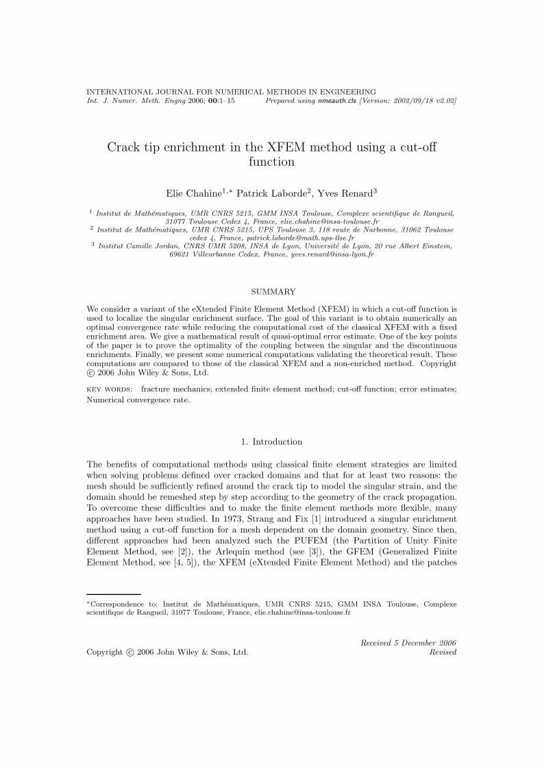
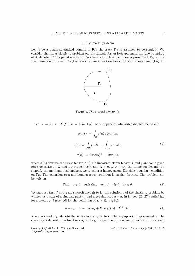
consider the linear elasticity problem on this domain for an isotropic material. The boundaryof Ω, denoted ∂Ω, is partitioned into ΓD where a Dirichlet condition is prescribed, ΓN with aNeumann condition and ΓC (the crack) where a traction free condition is considered (Fig. 1).
Figure 1. The cracked domain Ω.
Let ϑ = v ∈ H1(Ω); v = 0 on ΓD be the space of admissible displacements and
a(u, v) =
∫
Ω
σ(u) : ε(v) dx,
l(v) =
∫
Ω
f.vdx +
∫
ΓN
g.v dΓ,
σ(u) = λtrε(u)I + 2µε(u),
(1)
where σ(u) denotes the stress tensor, ε(u) the linearized strain tensor, f and g are some givenforce densities on Ω and ΓN respectively, and λ > 0, µ > 0 are the Lame coefficients. Tosimplify the mathematical analysis, we consider a homogeneous Dirichlet boundary conditionon ΓD. The extension to a non-homogeneous condition is straightforward. The problem canbe written
Find u ∈ ϑ such that a(u, v) = l(v) ∀v ∈ ϑ. (2)
We suppose that f and g are smooth enough to let the solution u of the elasticity problem bewritten as a sum of a singular part us and a regular part u − us in Ω (see [26, 27]) satisfyingfor a fixed ǫ > 0 (see [30] for the definition of Hs(Ω), s ∈ R):
u − us = u − (KIuI + KIIuII) ∈ H2+ǫ(Ω), (3)
where KI and KII denote the stress intensity factors. The asymptotic displacement at thecrack tip is defined from functions uI and uII , respectively the opening mode and the sliding
Copyright c© 2006 John Wiley & Sons, Ltd. Int. J. Numer. Meth. Engng 2006; 00:1–15Prepared using nmeauth.cls
4 E. CHAHINE, P. LABORDE, Y. RENARD
2
r
Gc
Crack tip
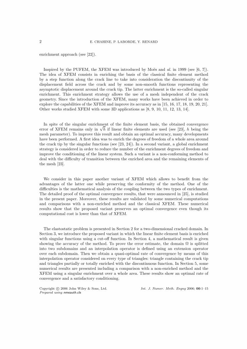
Figure 2. Polar coordinates respectively to the crack tip Ω.
mode for a two-dimensional crack given in polar coordinates by (see [28, 29]):
uI(r, θ) =1
E
√r
2π(1 + ν)
(cos θ
2 (δ − cos θ)
sin θ2 (δ − cos θ)
), (4)
uII(r, θ) =1
E
√r
2π(1 + ν)
(sin θ
2 (δ + 2 + cos θ)
cos θ2 (δ − 2 + cos θ)
), (5)
where ν denotes the Poisson ratio, E the Young modulus, δ = 3 − 4ν in the plane stressproblem and (r, θ) the polar coordinates respectively to the crack tip (fig. 2). The normal(respectively tangential) component of function uI(respectively uII) is discontinuous alongthe crack. Note that uI and uII belong to H3/2−η(Ω) for any η > 0 (see [26]) which limits theorder of the convergence rate of the classical finite element method to h1/2.
3. Discrete problem
The idea of the classical XFEM (see [6, 7]) is to use a finite element space enriched with someadditional functions. The finite element method is defined independently from the crack on amesh of the non-cracked domain Ω. At the nodes whose corresponding shape function supportis cut by the crack, an enrichment function of Heaviside type is considered:
H(x) =
+1 if (x − x∗) · n ≥ 0,
−1 elsewhere,(6)
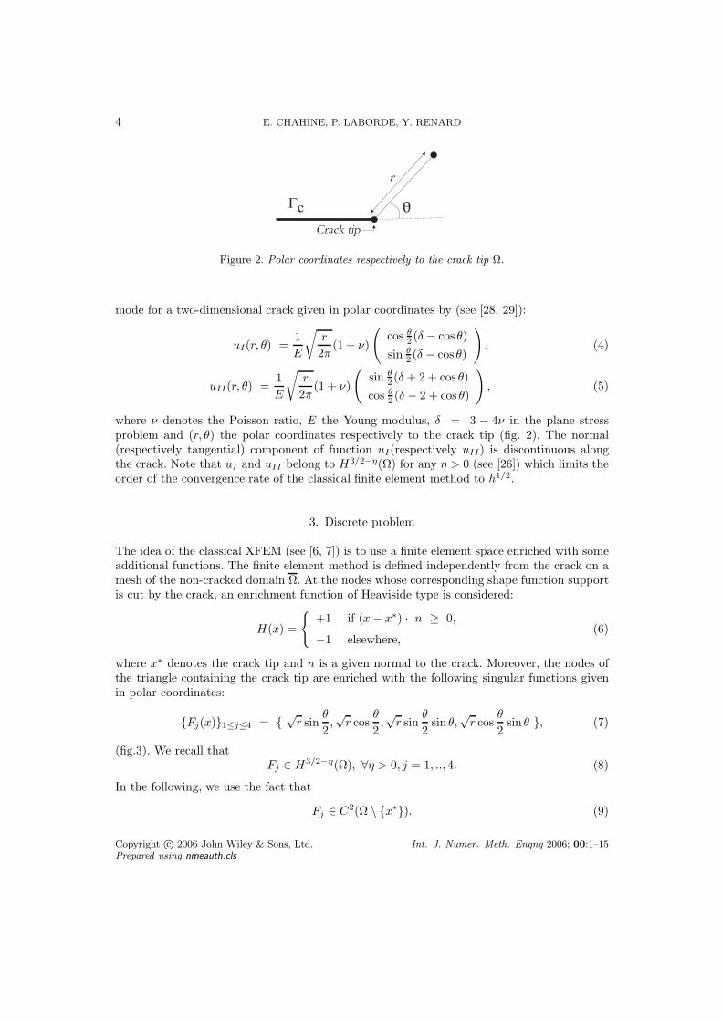
where x∗ denotes the crack tip and n is a given normal to the crack. Moreover, the nodes ofthe triangle containing the crack tip are enriched with the following singular functions givenin polar coordinates:
Fj(x)1≤j≤4 = √
r sinθ
2,√
r cosθ
2,√
r sinθ
2sin θ,
√r cos
θ
2sin θ , (7)
(fig.3). We recall thatFj ∈ H3/2−η(Ω), ∀η > 0, j = 1, .., 4. (8)
In the following, we use the fact that
Fj ∈ C2(Ω \ x∗). (9)
Copyright c© 2006 John Wiley & Sons, Ltd. Int. J. Numer. Meth. Engng 2006; 00:1–15Prepared using nmeauth.cls
CRACK TIP ENRICHMENT IN XFEM USING A CUT-OFF FUNCTION 5
The crack tip triangle(non enriched by H)
Non-enrichedtriangles
Triangles partiallyenriched by H
Triangles totallyenriched by H
Heaviside enrichment
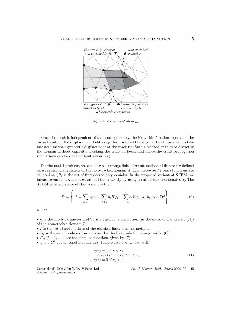
Figure 3. Enrichment strategy.
Since the mesh is independent of the crack geometry, the Heaviside function represents thediscontinuity of the displacement field along the crack and the singular functions allow to takeinto account the asymptotic displacement at the crack tip. Such a method enables to discretizethe domain without explicitly meshing the crack surfaces, and hence the crack propagationsimulations can be done without remeshing.
For the model problem, we consider a Lagrange finite element method of first order definedon a regular triangulation of the non-cracked domain Ω. The piecewise P1 basis functions aredenoted ϕi (P1 is the set of first degree polynomials). In the proposed variant of XFEM, weintend to enrich a whole area around the crack tip by using a cut-off function denoted χ. TheXFEM enriched space of this variant is then
ϑh =
vh =
∑
i∈I
aiϕi +∑
i∈IH
biHϕi +
4∑
j=1
cjFjχ; ai, bi, cj ∈ R2
, (10)
where
• h is the mesh parameter and Th is a regular triangulation (in the sense of the Ciarlet [31])of the non-cracked domain Ω,• I is the set of node indices of the classical finite element method,• IH is the set of node indices enriched by the Heaviside function given by (6)• Fj , j = 1, .., 4, are the singular functions given by (7)• χ is a C2 cut-off function such that there exists 0 < r0 < r1 with
χ(r) = 1 if r < r0,0 < χ(r) < 1 if r0 < r < r1,χ(r) = 0 if r1 < r.
(11)
Copyright c© 2006 John Wiley & Sons, Ltd. Int. J. Numer. Meth. Engng 2006; 00:1–15Prepared using nmeauth.cls
6 E. CHAHINE, P. LABORDE, Y. RENARD
The discrete problem can be written as follows
Find uh ∈ ϑh such that a(uh, vh) = l(vh) ∀vh ∈ ϑh. (12)
The proposed enrichment can be compared to the one of the classical XFEM, where thesingular enrichment term of (10) is replaced by
∑i∈Is
∑4j=1 cijFjϕi and where Is denotes the
set of degrees of freedom of the element containing the crack tip. It can be compared alsoto the XFEM with pointwise matching (introduced in [23]). In the latter one, the singular
enrichment term is written∑4
j=1 cjFjΛ, where Λ is equal to one on the enriched area, andzero otherwise. On the node of the interface between the enriched zone and the rest of themesh, a bonding condition is considered on the displacement field.
4. Error estimate
The mathematical result obtained in this work is the following:
Theorem 4.1. Assume that the displacement field u, solution to Problem (2), satisfiesCondition (3). Then, for any ǫ > 0, the following estimate holds
‖u − uh‖1,Ω ≤ Ch‖u − χus‖2+ǫ,Ω, (13)
where uh is the solution to Problem (12), ‖.‖s,Ω, s ∈ R stands for the norm in Hs(Ω) (see [30]for the definition of ‖.‖s,Ω), us is the singular part of u (see (3)), χ is the C2 cut-off functionand finally C > 0 is a constant independent of h.
Remark. When using a classical finite element method over a cracked domain, the erroris of order
√h while the displacement field belongs to H3/2−η, ∀η ≥ 0. The convergence rate
obtained here is identical to the one obtained when using a classical finite element methodof first order with a regular problem. The error estimate is not completely optimal due tothe requirement u − χus ∈ H2+ε(Ω) instead of u − χus ∈ H2(Ω). This is strictly a technicaldifficulty.
In order to compute the interpolation error, we introduce an interpolation operator Πh
adapted to the problem. This is done by using an extension of the displacement field acrossthe crack over Ω, then defining the interpolation of the displacement field using the extension(Lemma 4.3). The interpolation error estimates are then computed locally over every differenttype of triangles: triangles totally enriched by the discontinuous function (Lemma 4.4),triangles totally enriched by the singular functions (Lemma 4.5), triangles partially enrichedby the discontinuous function (Lemma 4.6) and finally non-enriched triangles.
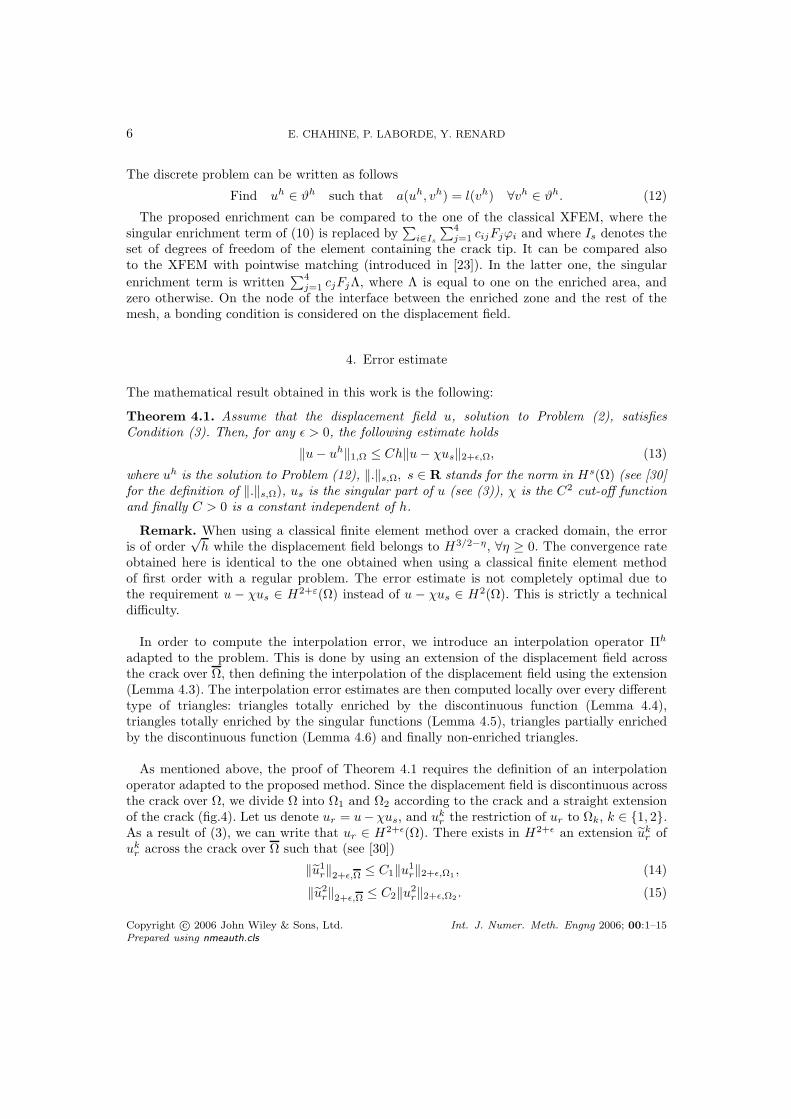
As mentioned above, the proof of Theorem 4.1 requires the definition of an interpolationoperator adapted to the proposed method. Since the displacement field is discontinuous acrossthe crack over Ω, we divide Ω into Ω1 and Ω2 according to the crack and a straight extensionof the crack (fig.4). Let us denote ur = u−χus, and uk
r the restriction of ur to Ωk, k ∈ 1, 2.As a result of (3), we can write that ur ∈ H2+ǫ(Ω). There exists in H2+ǫ an extension uk
r ofuk
r across the crack over Ω such that (see [30])
‖u1r‖2+ǫ,Ω ≤ C1‖u1
r‖2+ǫ,Ω1, (14)
‖u2r‖2+ǫ,Ω ≤ C2‖u2
r‖2+ǫ,Ω2. (15)
Copyright c© 2006 John Wiley & Sons, Ltd. Int. J. Numer. Meth. Engng 2006; 00:1–15Prepared using nmeauth.cls
CRACK TIP ENRICHMENT IN XFEM USING A CUT-OFF FUNCTION 7
Figure 4. Domain decomposition.
The use of such extensions allows us to interpolate over complete triangles and not over sub-triangles or quadrangles that are inducted because of the presence of a crack.
In the following, C denotes a generic constant that might be different at each occurrencebut is independent of h.
Definition 4.2. Given a displacement field u satisfying (3) and two extensions u1r and u2
r
respectively of u1 and u2 in H2+ǫ(Ω), we define Πhu as the element of ϑh such that
Πhu =∑
i∈I
aiϕi +∑
i∈IH
biHϕi +
4∑
i=1
ciFiχ, (16)
where ai, bi are given as follows (xi denotes the node associated to ϕi):
if i ∈ I \ IH then ai = ur(xi),
if i ∈ IH and xi ∈ Ωk then (k ∈ 1, 2, l 6= k)
ai = 1
2
(uk
r (xi) + ulr(xi)
),
bi = 12
(uk
r(xi) − ulr(xi)
)H(xi),
(17)
and ci, i = 1, .., 4 are derived from (4) and (5) such that∑
i ciFi = us.
Lemma 4.3. The function Πhu (Definition 4.2) verifies(i) Πhu = Ihur + χus over a triangle non-enriched by H,(ii) Πhu|K∩Ωk
= Ihukr + χus over a triangle K totally enriched by H,
where Ih denotes the classical interpolation operator for the associated finite element method.
Remark. Obviously, the definition of Πhu depends on the chosen extension ukr . From Lemma
4.3, the function Πhu is called the XFEM interpolation of u. Note that (16) and equations(i) and (ii) of Lemma 4.3 define a unique XFEM interpolation function Πhu over the wholedomain Ω. A similar construction of an interpolation operator taking only into account thediscontinuity across the crack was done in [32]. The definition of Πhu that we introduce isadapted to the presence of singularities.Proof. Equation (i) is directly derived from the first equation of (17) since Ih is the classicalinterpolation operator (see [31]). It means that a classical degree of freedom is equal to thenode value of ur if it is not enriched by H .
Copyright c© 2006 John Wiley & Sons, Ltd. Int. J. Numer. Meth. Engng 2006; 00:1–15Prepared using nmeauth.cls
8 E. CHAHINE, P. LABORDE, Y. RENARD
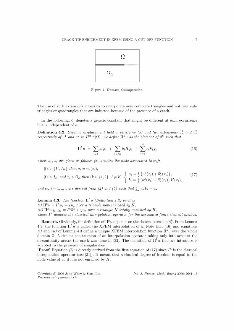
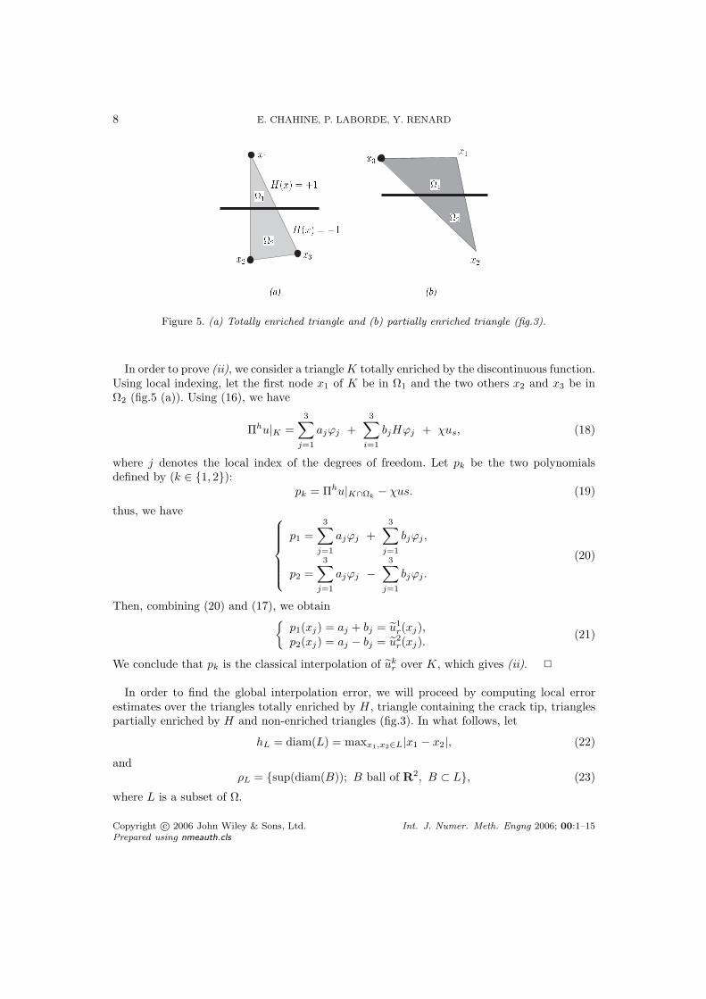
Figure 5. (a) Totally enriched triangle and (b) partially enriched triangle (fig.3).
In order to prove (ii), we consider a triangle K totally enriched by the discontinuous function.Using local indexing, let the first node x1 of K be in Ω1 and the two others x2 and x3 be inΩ2 (fig.5 (a)). Using (16), we have
Πhu|K =
3∑
j=1
ajϕj +
3∑
i=1
bjHϕj + χus, (18)
where j denotes the local index of the degrees of freedom. Let pk be the two polynomialsdefined by (k ∈ 1, 2):
pk = Πhu|K∩Ωk− χus. (19)
thus, we have
p1 =
3∑
j=1
ajϕj +
3∑
j=1
bjϕj ,
p2 =3∑
j=1
ajϕj −3∑
j=1
bjϕj .
(20)
Then, combining (20) and (17), we obtain
p1(xj) = aj + bj = u1r(xj),
p2(xj) = aj − bj = u2r(xj).
(21)
We conclude that pk is the classical interpolation of ukr over K, which gives (ii). 2
In order to find the global interpolation error, we will proceed by computing local errorestimates over the triangles totally enriched by H , triangle containing the crack tip, trianglespartially enriched by H and non-enriched triangles (fig.3). In what follows, let
hL = diam(L) = maxx1,x2∈L|x1 − x2|, (22)
andρL = sup(diam(B)); B ball of R
2, B ⊂ L, (23)
where L is a subset of Ω.
Copyright c© 2006 John Wiley & Sons, Ltd. Int. J. Numer. Meth. Engng 2006; 00:1–15Prepared using nmeauth.cls
CRACK TIP ENRICHMENT IN XFEM USING A CUT-OFF FUNCTION 9
Lemma 4.4. Let T Hh be the set of triangles totally enriched by H (fig.3) and σK = hKρ−1
K .For all K in T H
h , and for all u satisfying (3) we have the estimates
‖u − Πhu‖1,K∩Ω1≤ ChKσK‖u1
r‖2,K , (24)
and‖u − Πhu‖1,K∩Ω2
≤ ChKσK‖u2r‖2,K . (25)
In fact, the triangles totally enriched by H are cut into two parts. Using the extensions of u1r
and u2r, we associate three interpolation points to every part. Thus the interpolation operator
we defined, allows us to make a classical interpolation on every part of the triangle, and havethe same optimal rate of convergence obtained in the classical global interpolation theorem(see [1, 33]). Thus, Lemma 4.4 is a direct consequence of this theorem.
Lemma 4.5. Let K be the triangle containing the crack tip and K∗ = K \ΓC. Using the samenotations, we have the following estimate over K∗
‖u − Πhu‖1,K∗ ≤ ChKσK‖u − χus‖2+ǫ,Ω, (26)
where σK = hKρ−1K .
Proof. Since we added singular functions to the discrete space (around the crack tip), thesingular part of u (see (3)) will be eliminated when we try to estimate ‖u − Πhu‖1,K∗ . Thusit is sufficient to estimate ‖ur − Πhur‖1,K∗ where ur = u − χus. In fact
‖ur − Πhur‖21,K∗ = ‖ur − Πhur‖2
0,K∗ + |ur − Πhur|21,K∗ , (27)
where | · | denotes the H1 semi-norm. Using Sobolev imbedding theorems (see [30]), thespace H2+ǫ(Ω) (and not H2(Ω)) is continuously imbedded in C1
B(Ω), where C1B(Ω) = v ∈
C1(Ω) such that ∇v ∈ L∞(Ω) (see [30]). Thus
‖∇ur‖L∞(Ω) ≤ C‖ur‖2+ǫ,Ω = Cα (28)
where
‖∇Πhur‖L∞(K∗) ≤Cαd
ρK, (29)
where d ≤ h denotes the maximal distance between a node of K∗ and the crack tip. In fact,(ur − Πhur)(x) vanishes on the nodes, thus
‖ur − Πhur‖L∞(K∗) ≤Cαh2
K
ρK, (30)
then
‖ur − Πhur‖0,K∗ ≤[ ∫
K∗
(Cαh2
Kρ−1K
)2dx
]1/2
= Cαh2Kρ−1
K
√meas(K∗), (31)
and
|ur − Πhur|1,K∗ ≤[ ∫
K∗
(CαhKρ−1
K
)2dx
]1/2
= CαhKρ−1K
√meas(K∗). (32)
Finally we can write the following estimates
‖ur − Πhur‖0,K∗ ≤(Ch3
Kρ−1K
)‖ur‖2+ǫ,Ω,
|ur − Πhur|1,K∗ ≤(Ch2
Kρ−1K
)‖ur‖2+ǫ,Ω.
(33)
Using (27) we obtain (26).
Copyright c© 2006 John Wiley & Sons, Ltd. Int. J. Numer. Meth. Engng 2006; 00:1–15Prepared using nmeauth.cls
10 E. CHAHINE, P. LABORDE, Y. RENARD
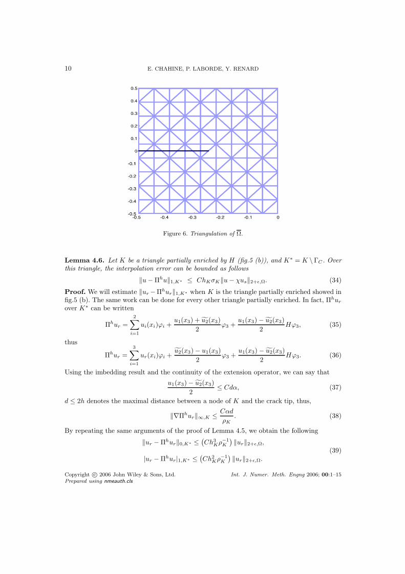
Figure 6. Triangulation of Ω.
Lemma 4.6. Let K be a triangle partially enriched by H (fig.5 (b)), and K∗ = K \ΓC . Overthis triangle, the interpolation error can be bounded as follows
‖u − Πhu‖1,K∗ ≤ ChKσK‖u − χus‖2+ǫ,Ω. (34)
Proof. We will estimate ‖ur −Πhur‖1,K∗ when K is the triangle partially enriched showed infig.5 (b). The same work can be done for every other triangle partially enriched. In fact, Πhur
over K∗ can be written
Πhur =
2∑
i=1
ui(xi)ϕi +u1(x3) + u2(x3)
2ϕ3 +
u1(x3) − u2(x3)
2Hϕ3, (35)
thus
Πhur =
3∑
i=1
ur(xi)ϕi +u2(x3) − u1(x3)
2ϕ3 +
u1(x3) − u2(x3)
2Hϕ3. (36)
Using the imbedding result and the continuity of the extension operator, we can say that
u1(x3) − u2(x3)
2≤ Cdα, (37)
d ≤ 2h denotes the maximal distance between a node of K and the crack tip, thus,
‖∇Πhur‖∞,K ≤ Cαd
ρK. (38)
By repeating the same arguments of the proof of Lemma 4.5, we obtain the following
‖ur − Πhur‖0,K∗ ≤(Ch3
Kρ−1K
)‖ur‖2+ǫ,Ω,
|ur − Πhur|1,K∗ ≤(Ch2
Kρ−1K
)‖ur‖2+ǫ,Ω.
(39)
Copyright c© 2006 John Wiley & Sons, Ltd. Int. J. Numer. Meth. Engng 2006; 00:1–15Prepared using nmeauth.cls
CRACK TIP ENRICHMENT IN XFEM USING A CUT-OFF FUNCTION 11
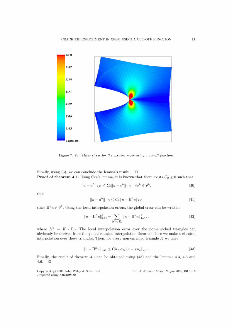
Figure 7. Von Mises stress for the opening mode using a cut-off function.
Finally, using (3), we can conclude the lemma’s result. 2
Proof of theorem 4.1. Using Cea’s lemma, it is known that there exists C0 ≥ 0 such that
‖u − uh‖1,Ω ≤ C0‖u − vh‖1,Ω ∀vh ∈ ϑh, (40)
thus
‖u − uh‖1,Ω ≤ C0‖u − Πhu‖1,Ω (41)
since Πhu ∈ ϑh. Using the local interpolation errors, the global error can be written
‖u − Πhu‖21,Ω =
∑
K∗∈Th
‖u − Πhu‖21,K∗ . (42)
where K∗ = K \ ΓC . The local interpolation error over the non-enriched triangles canobviously be derived from the global classical interpolation theorem, since we make a classicalinterpolation over these triangles. Then, for every non-enriched triangle K we have
‖u − Πhu‖1,K ≤ ChKσK‖u − χus‖2,K . (43)
Finally, the result of theorem 4.1 can be obtained using (43) and the lemmas 4.4, 4.5 and4.6. 2
Copyright c© 2006 John Wiley & Sons, Ltd. Int. J. Numer. Meth. Engng 2006; 00:1–15Prepared using nmeauth.cls
12 E. CHAHINE, P. LABORDE, Y. RENARD
39 45 49 55 59 65 69 75 79
1.28%
2.56%
5.12%
10.24%
20.48%
40.96%
81.92%
Number of cells in each direction
L2 r
ela
tive
err
or
Without enrichment, slope = −0.98202
XFEM (Enrichment radius = 0.2), slope = −2.009
Cutoff, slope = −1.8361
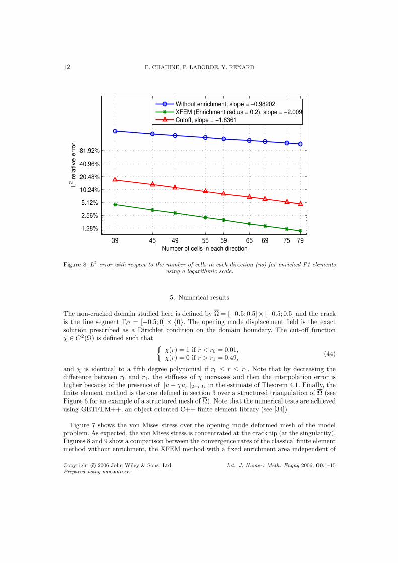
Figure 8. L2 error with respect to the number of cells in each direction (ns) for enriched P1 elements
using a logarithmic scale.
5. Numerical results
The non-cracked domain studied here is defined by Ω = [−0.5; 0.5]× [−0.5; 0.5] and the crackis the line segment ΓC = [−0.5; 0] × 0. The opening mode displacement field is the exactsolution prescribed as a Dirichlet condition on the domain boundary. The cut-off functionχ ∈ C2(Ω) is defined such that
χ(r) = 1 if r < r0 = 0.01,χ(r) = 0 if r > r1 = 0.49,
(44)
and χ is identical to a fifth degree polynomial if r0 ≤ r ≤ r1. Note that by decreasing thedifference between r0 and r1, the stiffness of χ increases and then the interpolation error ishigher because of the presence of ‖u − χus‖2+ǫ,Ω in the estimate of Theorem 4.1. Finally, thefinite element method is the one defined in section 3 over a structured triangulation of Ω (seeFigure 6 for an example of a structured mesh of Ω). Note that the numerical tests are achievedusing GETFEM++, an object oriented C++ finite element library (see [34]).
Figure 7 shows the von Mises stress over the opening mode deformed mesh of the modelproblem. As expected, the von Mises stress is concentrated at the crack tip (at the singularity).Figures 8 and 9 show a comparison between the convergence rates of the classical finite elementmethod without enrichment, the XFEM method with a fixed enrichment area independent of
Copyright c© 2006 John Wiley & Sons, Ltd. Int. J. Numer. Meth. Engng 2006; 00:1–15Prepared using nmeauth.cls
CRACK TIP ENRICHMENT IN XFEM USING A CUT-OFF FUNCTION 13
39 45 49 55 59 65 69 75 79
1.31072%
2.62144%
5.24288%
10.4858%
20.9715%
41.943%
Number of cells in each direction
H1 r
ela
tive
err
or
Without enrichment, slope = −0.50086
XFEM (Enrichment radius = 0.2), slope = −1.0252
Cutoff, slope = −0.96356
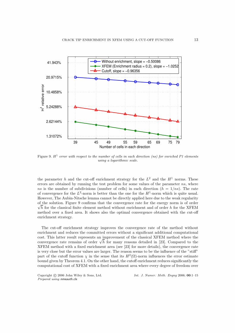
Figure 9. H1 error with respect to the number of cells in each direction (ns) for enriched P1 elements
using a logarithmic scale.
the parameter h and the cut-off enrichment strategy for the L2 and the H1 norms. Theseerrors are obtained by running the test problem for some values of the parameter ns, wherens is the number of subdivisions (number of cells) in each direction (h = 1/ns). The rateof convergence for the L2-norm is better than the one for the H1-norm which is quite usual.However, The Aubin-Nitsche lemma cannot be directly applied here due to the weak regularityof the solution. Figure 9 confirms that the convergence rate for the energy norm is of order√
h for the classical finite element method without enrichment and of order h for the XFEMmethod over a fixed area. It shows also the optimal convergence obtained with the cut-offenrichment strategy.
The cut-off enrichment strategy improves the convergence rate of the method withoutenrichment and reduces the committed errors without a significant additional computationalcost. This latter result represents an improvement of the classical XFEM method where theconvergence rate remains of order
√h for many reasons detailed in [23]. Compared to the
XFEM method with a fixed enrichment area (see [23] for more details), the convergence rateis very close but the error values are larger. The reason seems to be the influence of the ”stiff”part of the cutoff function χ in the sense that its H2(Ω)-norm influences the error estimatebound given by Theorem 4.1. On the other hand, the cutoff enrichment reduces significantly thecomputational cost of XFEM with a fixed enrichment area where every degree of freedom over
Copyright c© 2006 John Wiley & Sons, Ltd. Int. J. Numer. Meth. Engng 2006; 00:1–15Prepared using nmeauth.cls
14 E. CHAHINE, P. LABORDE, Y. RENARD
40 46 50 56 60 66 70 76 80
2.62144%
5.24288%
10.4858%
20.9715%
Number of cells in each direction
H1 r
ela
tive
err
or
Cutoff comparison
Cutoff r1=0.01,r
0=0.49, slope = −0.92734
Cutoff r1=0.05,r
0=0.49, slope = −0.91035
Cutoff r1=0.15,r
0=0.49, slope = −0.83322
Cutoff r1=0.01,r
0=0.39, slope = −0.91061
Cutoff r1=0.1,r
0=0.4, slope = −0.83952
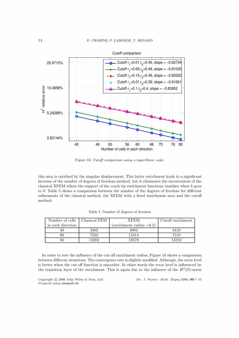
Figure 10. Cutoff comparison using a logarithmic scale.
this area is enriched by the singular displacement. This latter enrichment leads to a significantincrease of the number of degrees of freedom method, but it eliminates the inconvenient of theclassical XFEM where the support of the crack tip enrichment functions vanishes when h goesto 0. Table 5 shows a comparison between the number of the degrees of freedom for differentrefinements of the classical method, the XFEM with a fixed enrichment area and the cutoffmethod.
Table I. Number of degrees of freedom
Number of cells Classical FEM XFEM Cutoff enrichmentin each direction (enrichment radius =0.2)
40 3402 4962 341060 7502 11014 751080 13202 19578 13210
In order to test the influence of the cut-off enrichment radius, Figure 10 shows a comparisonbetween different situations. The convergence rate is slightly modified. Although, the error levelis better when the cut-off function is smoother. In other words the error level is influenced bythe transition layer of the enrichment. This is again due to the influence of the H2(Ω)-norm
Copyright c© 2006 John Wiley & Sons, Ltd. Int. J. Numer. Meth. Engng 2006; 00:1–15Prepared using nmeauth.cls
CRACK TIP ENRICHMENT IN XFEM USING A CUT-OFF FUNCTION 15
of the cutoff function (see (4.1)).
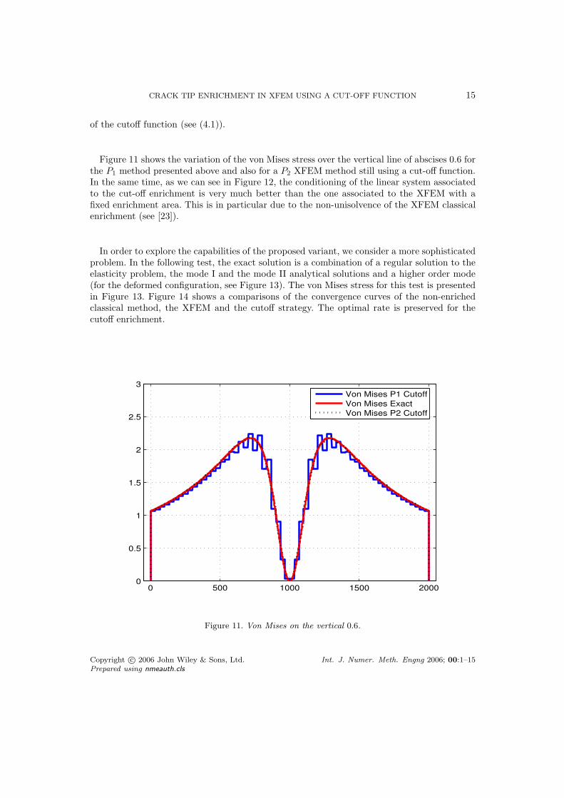
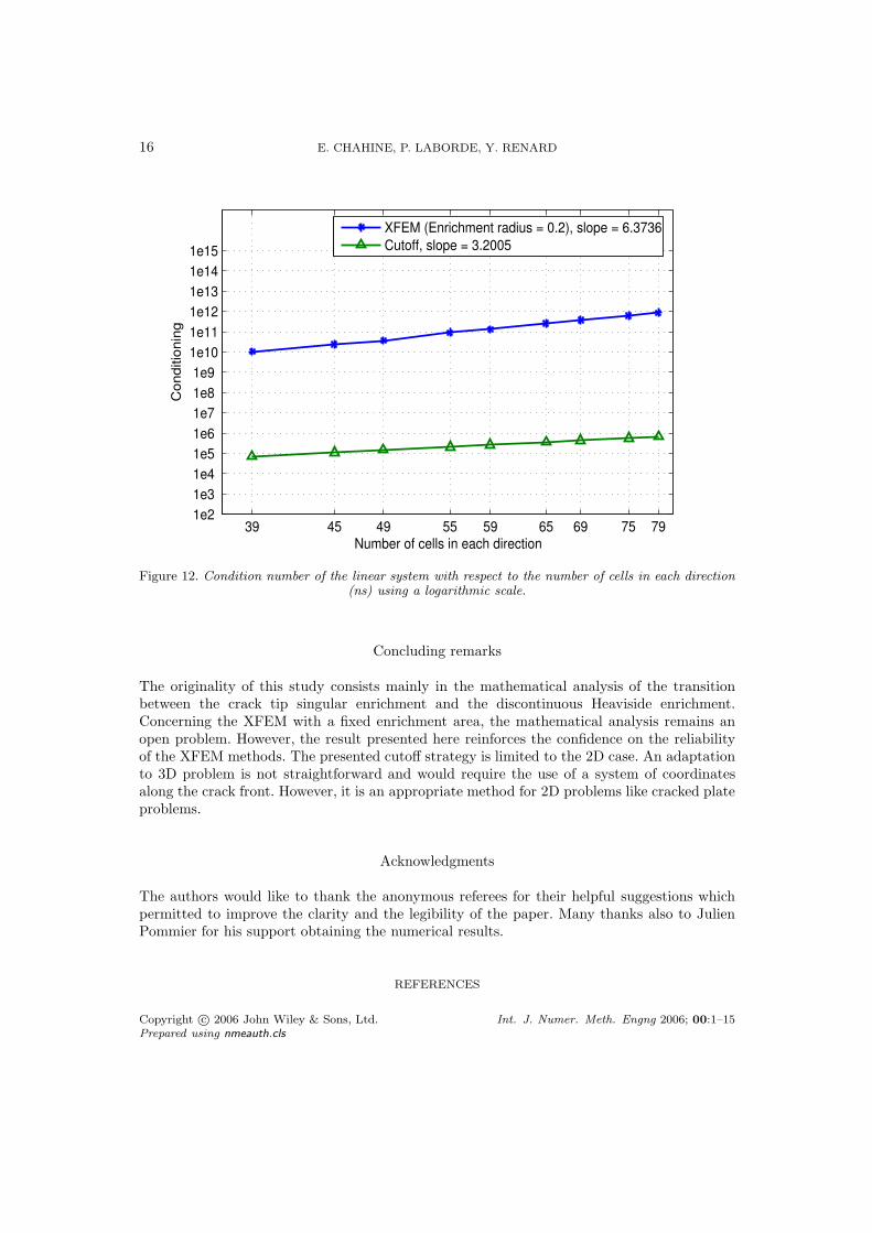
Figure 11 shows the variation of the von Mises stress over the vertical line of abscises 0.6 forthe P1 method presented above and also for a P2 XFEM method still using a cut-off function.In the same time, as we can see in Figure 12, the conditioning of the linear system associatedto the cut-off enrichment is very much better than the one associated to the XFEM with afixed enrichment area. This is in particular due to the non-unisolvence of the XFEM classicalenrichment (see [23]).
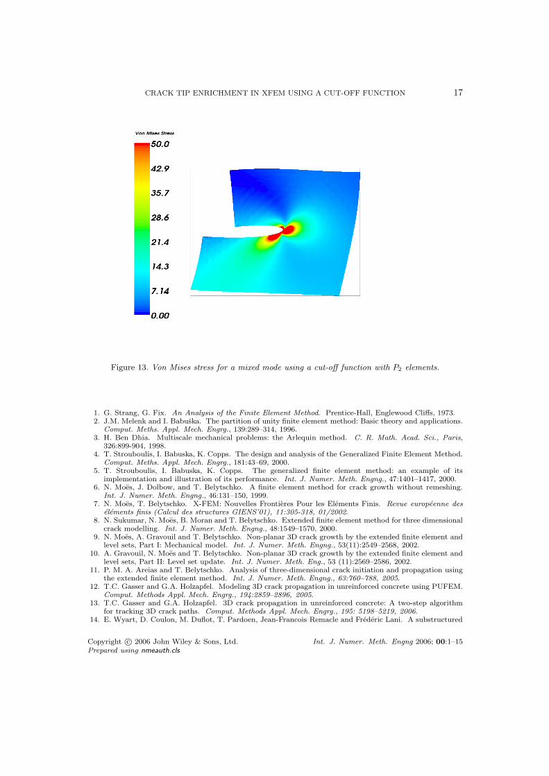
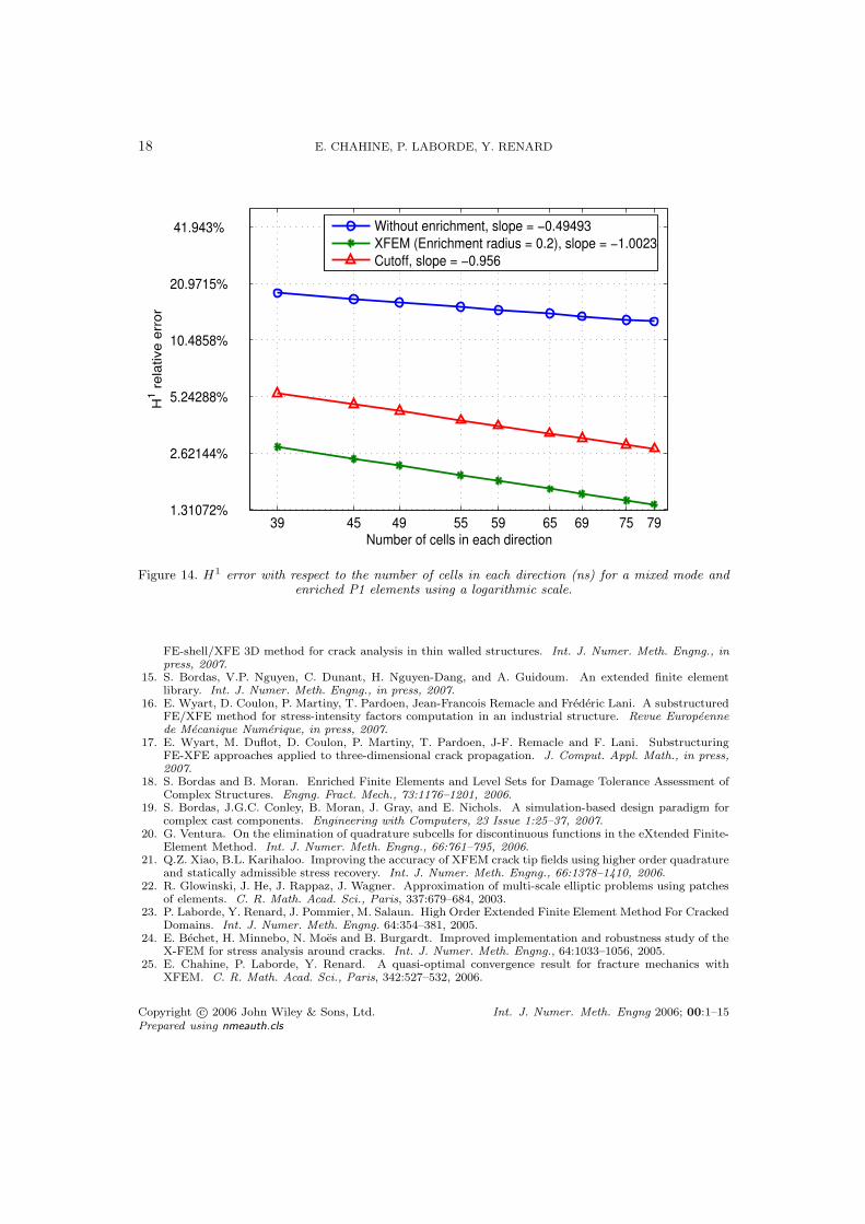
In order to explore the capabilities of the proposed variant, we consider a more sophisticatedproblem. In the following test, the exact solution is a combination of a regular solution to theelasticity problem, the mode I and the mode II analytical solutions and a higher order mode(for the deformed configuration, see Figure 13). The von Mises stress for this test is presentedin Figure 13. Figure 14 shows a comparisons of the convergence curves of the non-enrichedclassical method, the XFEM and the cutoff strategy. The optimal rate is preserved for thecutoff enrichment.
0 500 1000 1500 20000
0.5
1
1.5
2
2.5
3
Von Mises P1 Cutoff
Von Mises Exact
Von Mises P2 Cutoff
Figure 11. Von Mises on the vertical 0.6.
Copyright c© 2006 John Wiley & Sons, Ltd. Int. J. Numer. Meth. Engng 2006; 00:1–15Prepared using nmeauth.cls
16 E. CHAHINE, P. LABORDE, Y. RENARD
39 45 49 55 59 65 69 75 791e2
1e3
1e4
1e5
1e6
1e7
1e8
1e9
1e10
1e11
1e12
1e13
1e14
1e15
Number of cells in each direction
Co
nd
itio
nin
g
XFEM (Enrichment radius = 0.2), slope = 6.3736
Cutoff, slope = 3.2005
Figure 12. Condition number of the linear system with respect to the number of cells in each direction(ns) using a logarithmic scale.
Concluding remarks
The originality of this study consists mainly in the mathematical analysis of the transitionbetween the crack tip singular enrichment and the discontinuous Heaviside enrichment.Concerning the XFEM with a fixed enrichment area, the mathematical analysis remains anopen problem. However, the result presented here reinforces the confidence on the reliabilityof the XFEM methods. The presented cutoff strategy is limited to the 2D case. An adaptationto 3D problem is not straightforward and would require the use of a system of coordinatesalong the crack front. However, it is an appropriate method for 2D problems like cracked plateproblems.
Acknowledgments
The authors would like to thank the anonymous referees for their helpful suggestions whichpermitted to improve the clarity and the legibility of the paper. Many thanks also to JulienPommier for his support obtaining the numerical results.
REFERENCES
Copyright c© 2006 John Wiley & Sons, Ltd. Int. J. Numer. Meth. Engng 2006; 00:1–15Prepared using nmeauth.cls
CRACK TIP ENRICHMENT IN XFEM USING A CUT-OFF FUNCTION 17
Figure 13. Von Mises stress for a mixed mode using a cut-off function with P2 elements.
1. G. Strang, G. Fix. An Analysis of the Finite Element Method. Prentice-Hall, Englewood Cliffs, 1973.2. J.M. Melenk and I. Babuska. The partition of unity finite element method: Basic theory and applications.
Comput. Meths. Appl. Mech. Engrg., 139:289–314, 1996.3. H. Ben Dhia. Multiscale mechanical problems: the Arlequin method. C. R. Math. Acad. Sci., Paris,
326:899-904, 1998.4. T. Strouboulis, I. Babuska, K. Copps. The design and analysis of the Generalized Finite Element Method.
Comput. Meths. Appl. Mech. Engrg., 181:43–69, 2000.5. T. Strouboulis, I. Babuska, K. Copps. The generalized finite element method: an example of its
implementation and illustration of its performance. Int. J. Numer. Meth. Engng., 47:1401–1417, 2000.6. N. Moes, J. Dolbow, and T. Belytschko. A finite element method for crack growth without remeshing.
Int. J. Numer. Meth. Engng., 46:131–150, 1999.7. N. Moes, T. Belytschko. X-FEM: Nouvelles Frontieres Pour les Elements Finis. Revue europeenne des
elements finis (Calcul des structures GIENS’01), 11:305-318, 01/2002.8. N. Sukumar, N. Moes, B. Moran and T. Belytschko. Extended finite element method for three dimensional
crack modelling. Int. J. Numer. Meth. Engng., 48:1549–1570, 2000.9. N. Moes, A. Gravouil and T. Belytschko. Non-planar 3D crack growth by the extended finite element and
level sets, Part I: Mechanical model. Int. J. Numer. Meth. Engng., 53(11):2549–2568, 2002.10. A. Gravouil, N. Moes and T. Belytschko. Non-planar 3D crack growth by the extended finite element and
level sets, Part II: Level set update. Int. J. Numer. Meth. Eng., 53 (11):2569–2586, 2002.11. P. M. A. Areias and T. Belytschko. Analysis of three-dimensional crack initiation and propagation using
the extended finite element method. Int. J. Numer. Meth. Engng., 63:760–788, 2005.12. T.C. Gasser and G.A. Holzapfel. Modeling 3D crack propagation in unreinforced concrete using PUFEM.
Comput. Methods Appl. Mech. Engrg., 194:2859–2896, 2005.13. T.C. Gasser and G.A. Holzapfel. 3D crack propagation in unreinforced concrete: A two-step algorithm
for tracking 3D crack paths. Comput. Methods Appl. Mech. Engrg., 195: 5198–5219, 2006.14. E. Wyart, D. Coulon, M. Duflot, T. Pardoen, Jean-Francois Remacle and Frederic Lani. A substructured
Copyright c© 2006 John Wiley & Sons, Ltd. Int. J. Numer. Meth. Engng 2006; 00:1–15Prepared using nmeauth.cls
18 E. CHAHINE, P. LABORDE, Y. RENARD
39 45 49 55 59 65 69 75 791.31072%
2.62144%
5.24288%
10.4858%
20.9715%
41.943%
Number of cells in each direction
H1 r
ela
tive
err
or
Without enrichment, slope = −0.49493
XFEM (Enrichment radius = 0.2), slope = −1.0023
Cutoff, slope = −0.956
Figure 14. H1 error with respect to the number of cells in each direction (ns) for a mixed mode and
enriched P1 elements using a logarithmic scale.
FE-shell/XFE 3D method for crack analysis in thin walled structures. Int. J. Numer. Meth. Engng., inpress, 2007.
15. S. Bordas, V.P. Nguyen, C. Dunant, H. Nguyen-Dang, and A. Guidoum. An extended finite elementlibrary. Int. J. Numer. Meth. Engng., in press, 2007.
16. E. Wyart, D. Coulon, P. Martiny, T. Pardoen, Jean-Francois Remacle and Frederic Lani. A substructuredFE/XFE method for stress-intensity factors computation in an industrial structure. Revue Europeennede Mecanique Numerique, in press, 2007.
17. E. Wyart, M. Duflot, D. Coulon, P. Martiny, T. Pardoen, J-F. Remacle and F. Lani. SubstructuringFE-XFE approaches applied to three-dimensional crack propagation. J. Comput. Appl. Math., in press,2007.
18. S. Bordas and B. Moran. Enriched Finite Elements and Level Sets for Damage Tolerance Assessment ofComplex Structures. Engng. Fract. Mech., 73:1176–1201, 2006.
19. S. Bordas, J.G.C. Conley, B. Moran, J. Gray, and E. Nichols. A simulation-based design paradigm forcomplex cast components. Engineering with Computers, 23 Issue 1:25–37, 2007.
20. G. Ventura. On the elimination of quadrature subcells for discontinuous functions in the eXtended Finite-Element Method. Int. J. Numer. Meth. Engng., 66:761–795, 2006.
21. Q.Z. Xiao, B.L. Karihaloo. Improving the accuracy of XFEM crack tip fields using higher order quadratureand statically admissible stress recovery. Int. J. Numer. Meth. Engng., 66:1378–1410, 2006.
22. R. Glowinski, J. He, J. Rappaz, J. Wagner. Approximation of multi-scale elliptic problems using patchesof elements. C. R. Math. Acad. Sci., Paris, 337:679–684, 2003.
23. P. Laborde, Y. Renard, J. Pommier, M. Salaun. High Order Extended Finite Element Method For CrackedDomains. Int. J. Numer. Meth. Engng. 64:354–381, 2005.
24. E. Bechet, H. Minnebo, N. Moes and B. Burgardt. Improved implementation and robustness study of theX-FEM for stress analysis around cracks. Int. J. Numer. Meth. Engng., 64:1033–1056, 2005.
25. E. Chahine, P. Laborde, Y. Renard. A quasi-optimal convergence result for fracture mechanics withXFEM. C. R. Math. Acad. Sci., Paris, 342:527–532, 2006.
Copyright c© 2006 John Wiley & Sons, Ltd. Int. J. Numer. Meth. Engng 2006; 00:1–15Prepared using nmeauth.cls
CRACK TIP ENRICHMENT IN XFEM USING A CUT-OFF FUNCTION 19
26. P. Grisvard. Singularities in boundary value problems. Masson, 1992.27. P. Grisvard. Problemes aux limites dans les polygones - Mode d’emploi. EDF Bull. Directions Etudes
Rech. Ser. C. Math. Inform. 1, MR 87g:35073, 21–59, 1986.28. J. Lemaitre, J.-L. Chaboche Mechanics of Solid Materials. Cambridge University Press, 1994.29. J. B. Leblond. Mecanique de la Rupture Fragile et Ductile. Hermes, Lavoisier, 2003.30. R. A. Adams. Sobolev Spaces. Academic Press, 1975.31. P. G. Ciarlet. The Finite Element Method For Elliptic Problems. North Holland Publishing Company,
1979.32. A. Hansbo, P. Hansbo. A Finite Element Method for the Simulation of Strong and Weak Discontinuities
in Solid Mechanics. Comput. Methods Appl. Mech. Engrg., 193:3523–3540, 2004.33. A. Ern, J.L. Guermond. Elements finis: theorie, applications, mise en œuvre. Springer, 2001.34. Y. Renard, J. Pommier. An open source generic C++ library for finite element methods. http://www-
gmm.insa-toulouse.fr/getfem.
Copyright c© 2006 John Wiley & Sons, Ltd. Int. J. Numer. Meth. Engng 2006; 00:1–15Prepared using nmeauth.cls