Control of Power in a Transmission Line by Distributed ...irphouse.com/ijee/ijeev5n4_04.pdf ·...
16
International Journal of Electrical Engineering. ISSN 0974-2158 Volume 5, Number 4 (2012), pp. 411-425 © International Research Publication House http://www.irphouse.com Control of Power in a Transmission Line by Distributed Power-Flow Controller (DPFC) P. Ramesh 1 and Dr. M. Damodara Reddy 2 1 Research Scholar, Department of Electrical and Electronics Engineering, SVU College of Engineering, S V University, Tirupati, A.P., India 2 Associate Professor, Department of Electrical and Electronics Engineering, SVU College of Engineering, S V University, Tirupati, A.P., India. E-mail: [email protected], [email protected] Abstract The present paper describes the steady-state response and control of power in Transmission line equipped with FACTS devices. Detailed simulations are carried out on two- machine systems to illustrate the control features of these devices and their influence to increase power transfer capability and improve system Reliability. The DPFC is derived from the unified power-flow controller (UPFC) and DPFC has the same control capability as the UPFC. The DPFC can be considered as a UPFC with an eliminated common dc link. The active power exchange between the shunt and series converters, which is through the common dc link in the UPFC, is now through the transmission lines at the third-harmonic frequency. The interaction between the DPFC, the network and the machines are analyzed. Index Terms: FACTS,DPFC, device modeling, power transmission AC–DC power conversion, power semiconductor devices, power system control, power - transmission control. Introduction The flexible ac transmission system (FACTS) technology is the application of power electronics in transmission systems [1]. The main purpose of this technology is to control and regulate the electric variables in the power systems. This is achieved by using converters as a controllable interface between two power system terminals. The resulting converter representations can be useful for a variety of configurations. Basically, the family of FACTS devices based on voltage source converters (VSCs) consists of a series compensator, a shunt compensator, and
Transcript of Control of Power in a Transmission Line by Distributed ...irphouse.com/ijee/ijeev5n4_04.pdf ·...
International Journal of Electrical Engineering. ISSN 0974-2158 Volume 5, Number 4 (2012), pp. 411-425 © International Research Publication House http://www.irphouse.com
Control of Power in a Transmission Line by Distributed Power-Flow Controller (DPFC)
P. Ramesh1 and Dr. M. Damodara Reddy2
1Research Scholar, Department of Electrical and Electronics Engineering, SVU College of Engineering, S V University, Tirupati, A.P., India
2Associate Professor, Department of Electrical and Electronics Engineering, SVU College of Engineering, S V University, Tirupati, A.P., India. E-mail: [email protected], [email protected]
Abstract
The present paper describes the steady-state response and control of power in Transmission line equipped with FACTS devices. Detailed simulations are carried out on two- machine systems to illustrate the control features of these devices and their influence to increase power transfer capability and improve system Reliability. The DPFC is derived from the unified power-flow controller (UPFC) and DPFC has the same control capability as the UPFC. The DPFC can be considered as a UPFC with an eliminated common dc link. The active power exchange between the shunt and series converters, which is through the common dc link in the UPFC, is now through the transmission lines at the third-harmonic frequency. The interaction between the DPFC, the network and the machines are analyzed. Index Terms: FACTS,DPFC, device modeling, power transmission AC–DC power conversion, power semiconductor devices, power system control, power - transmission control.
Introduction The flexible ac transmission system (FACTS) technology is the application of power electronics in transmission systems [1]. The main purpose of this technology is to control and regulate the electric variables in the power systems. This is achieved by using converters as a controllable interface between two power system terminals. The resulting converter representations can be useful for a variety of configurations. Basically, the family of FACTS devices based on voltage source converters (VSCs) consists of a series compensator, a shunt compensator, and
412 P. Ramesh and Dr. M. Damodara Reddy
a shunt/series compensator. The static Compensator (STATCOM) [2] is a shunt connected device that is able to provide reactive power support at a network location far away from the generators. Through this reactive power injection, the STATCOM can regulate the voltage at the connection node. The static synchronous series compensator (SSSC) [2] is a series device which injects a voltage in series with the transmission line. Ideally, this injected voltage is in quadrature with the line current, such that the SSSC behaves like an inductor or a capacitor for the purpose of increasing or decreasing the overall reactive voltage drop across the line, and thereby, controlling the transmitted power. In this operating mode, the SSSC does not interchange any real power with the system in steady-state. The unified power-flow controller (UPFC) [2] is the most versatile device of the family of FACTS devices, since it is able to control the active and the reactive power, respectively, as well as the voltage at the connection node. The Unified Power Flow Controller (UPFC) is comprised of a STATCOM and a SSSC [3], coupled via a common DC link to allow bi-directional flow of active power between the series output terminals of the SSSC and the shunt output terminals of the STATCOM [4].Each converter can independently generate (or) absorb reactive power at its own AC terminal. The two converters are operated from a DC link provided by a DC storage capacitor. The UPFC is not widely applied in practice, due to their high cost and the susceptibility to failures. Generally, the reliability can be improved by reducing the number of components; however, this is not possible due to the complex topology of the UPFC. To reduce the failure rate of the components, selecting components with higher ratings than necessary or employing redundancy at the component or system levels. Unfortunately, these solutions increase the initial investment necessary, negating any cost related advantages. Accordingly, new approaches are needed in order to increase reliability and reduce cost of the UPFC. The same as the UPFC, the DPFC is able to control all system parameters like line impedance, transmission angle & bus voltage. The DPFC eliminates the common dc link between the shunt and series converters. The active power exchange between the shunt and the series converter is through the transmission line at the third-harmonic frequency. The series converter of the DPFC employs the distributed FACTS (D-FACTS) concept [5]. Comparing with the UPFC, the DPFC have two major advantages: 1) low cost because of the low-voltage isolation and the low component rating of the series converter and 2) High reliability because of the redundancy of the series converters and high control capability. DPFC can also be used to improve the power quality and system stability such as power oscillation damping [6], Voltage sag restoration or balancing asymmetry. DPFC Topology Similar as the UPFC, the DPFC consists of shunt and series connected converters. The shunt converter is similar as a STATCOM, while the series converter employs the Distributed Static series compensator (DSSC) concept, which is to use multiple single-phase converters instead of one three-phase converter. Each converter within
Control of Power in a Tra
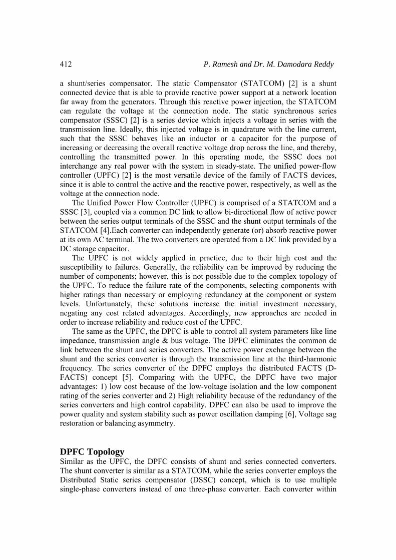
the DPFC is independent voltage. The configuration As shown, besides therequires a high pass filter line and a Y- Δ transforcomponents will be explai
DPFC Operating PrinActive power exchange wWithin the DPFC, the traAC ports of the shunt andactive power through the sinusoidal components. Acurrent can be expressed with different amplitudes. and current is defined as tthe integrals of all the croactive power can be expre
1
i ii
P V I∞
=
=∑ Where Vi and Ii arerespectively, and iφ is thEquation (1) shows that tfrom each other and the vactive power at other freqfrequencies gives the possactive power at one freque By applying this metpower from the grid at thharmonic frequency. Thisequipped with series conv
ansmission Line
and has its own DC capacitor to provide thn of the DPFC is shown in Figure 1. e key components- shunt and series converterthat is shunt connected to the other side of th
rmer on each side of the line. The reason ined later.
Figure 1: DPFC configuration.
nciple with eliminated DC link: ansmission line presents a common connectid the series converters. Therefore, it is possib
AC ports. The method is based on power ccording to the Fourier analysis, non-sinusoias the sum of sinusoidal functions in differThe active power resulting from this non-sin
the mean value of the product of voltage andoss product of terms with different frequencissed by:
cos iφ …………
e the voltage and current at the ith harmhe corresponding angle between the voltagthe active powers at different frequencies avoltage or current at one frequency has no inquencies. The independence of the active powsibility that a converter without a power sourency and absorb this power from other frequethod to the DPFC, the shunt converter canhe fundamental frequency and inject the pos harmonic active power flows through a traverters. According to the amount of required
413
he required DC
rs, a DPFC also he transmission for these extra
on between the ble to exchange theory of non-
idal voltage and rent frequencies nusoidal voltage d current. Since ies are zero, the
(1)
onic frequency ge and current. are independent nfluence on the wer at different
rce can generate encies. n absorb active ower back at a ansmission line active power at
414
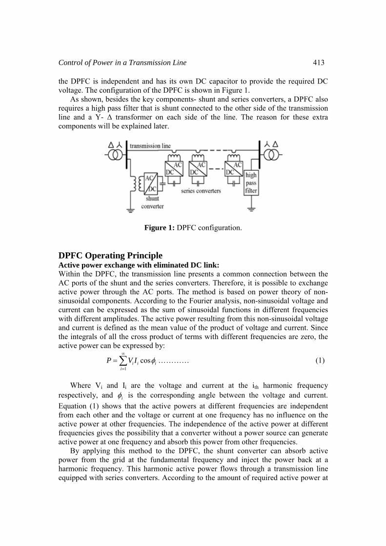
the fundamental frequencharmonic frequency, there Neglecting losses, theequal to the power absorbepower is exchanged betwe
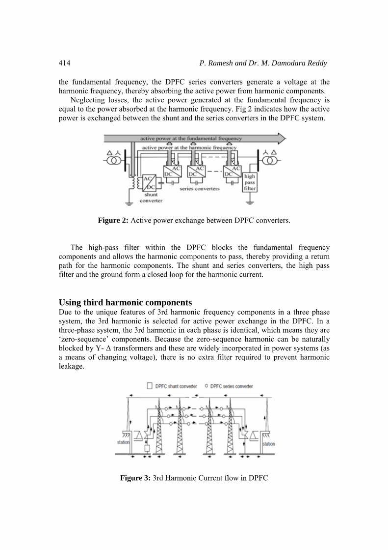
Figure 2: Act The high-pass filter components and allows thpath for the harmonic cofilter and the ground form Using third harmonicDue to the unique featuresystem, the 3rd harmonicthree-phase system, the 3r‘zero-sequence’ componeblocked by Y- Δ transforma means of changing voltleakage.
Figure
P. Ramesh and Dr. M. Da
cy, the DPFC series converters generate a eby absorbing the active power from harmonie active power generated at the fundamented at the harmonic frequency. Fig 2 indicateseen the shunt and the series converters in the D
tive power exchange between DPFC converte
within the DPFC blocks the fundamehe harmonic components to pass, thereby proomponents. The shunt and series converters
a closed loop for the harmonic current.
c components es of 3rd harmonic frequency components inc is selected for active power exchange in trd harmonic in each phase is identical, which nts. Because the zero-sequence harmonic c
mers and these are widely incorporated in powtage), there is no extra filter required to pre
e 3: 3rd Harmonic Current flow in DPFC
amodara Reddy
voltage at the c components. al frequency is s how the active DPFC system.
ers.
ntal frequency oviding a return , the high pass
n a three phase the DPFC. In a means they are an be naturally wer systems (as event harmonic

Control of Power in a Tra
As introduced above, harmonic current and thfundamental frequency. Bfrequency is close to the cu By using the zero-sequthat connects the neutral pΔ -winding appears open-cflow through the Y-windin
Figure 4: Utilize grou The harmonic at the frcan be used to exchange selected, because it is the l DPFC Control To control multiple convcentral control, shunt cont
Fig Central Control The central control geneconverters of the DPFC. Isuch as power-flow contro
ansmission Line
a high-pass filter is required to make a closhe cutoff frequency of this filter is appBecause the voltage isolation is high andutoff frequency, the filter will be costly. uence harmonic, the costly filter can be replapoint of the Y- Δ transformer on the right sidcircuit to the 3rd harmonic current, all harmong and concentrate to the grounding cable as
unded Y- Δ transformer to filter zero-sequence
frequencies like 3rd, 6th, 9th... are all zero-seactive power in the DPFC. However, the 3
lowest frequency among all zero-sequence ha
verters [7], a DPFC consists of three types trol and series control, as shown in Figure 5.
gure 5: DPFC control block diagram.
erates the reference signals for both the shIt is focused on the DPFC tasks at the poweol, low-frequency power oscillation damping
415
sed loop for the proximately the d the harmonic
aced by a cable de. Because the
onic current will shown in Fig 4.
e harmonic.
equence and all 3rd harmonic is armonics.
of controllers:
hunt and series er-system level, g, and balancing
416
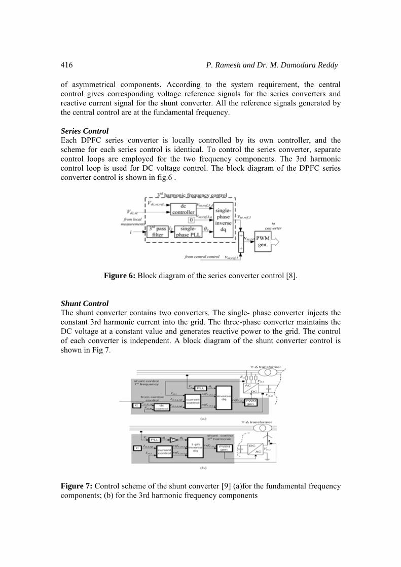
of asymmetrical componcontrol gives correspondireactive current signal forthe central control are at th Series Control Each DPFC series convescheme for each series cocontrol loops are employcontrol loop is used for Dconverter control is shown
Figure 6: Bl Shunt Control The shunt converter contaconstant 3rd harmonic curDC voltage at a constant of each converter is indepshown in Fig 7.
Figure 7: Control schemecomponents; (b) for the 3r
P. Ramesh and Dr. M. Da
nents. According to the system requiremeing voltage reference signals for the series r the shunt converter. All the reference signahe fundamental frequency.
erter is locally controlled by its own contontrol is identical. To control the series conyed for the two frequency components. TheDC voltage control. The block diagram of thn in fig.6 .
ock diagram of the series converter control [8
ains two converters. The single- phase converrent into the grid. The three-phase convertevalue and generates reactive power to the grpendent. A block diagram of the shunt conv
e of the shunt converter [9] (a)for the fundamrd harmonic frequency components
amodara Reddy
ent, the central converters and
als generated by
troller, and the nverter, separate e 3rd harmonic he DPFC series
8].
erter injects the er maintains the rid. The control verter control is
mental frequency
Control of Power in a Tra
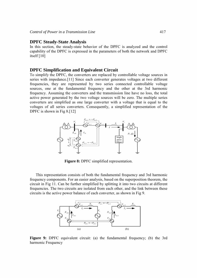
DPFC Steady-State AIn this section, the steadycapability of the DPFC is itself [10] DPFC Simplification To simplify the DPFC, thseries with impedance.[11frequencies, they are resources, one at the fundfrequency. Assuming the active power generated byconverters are simplified voltages of all series conDPFC is shown in Fig 8.[1
Figu This representation cofrequency components. Focircuit in Fig 11. Can be ffrequencies. The two circucircuits is the active power
Figure 9: DPFC equivaharmonic Frequency
ansmission Line
Analysis y-state behavior of the DPFC is analyzed aexpressed in the parameters of both the netw
and Equivalent Circuit e converters are replaced by controllable vol1] Since each converter generates voltages aepresented by two series connected controdamental frequency and the other at the converters and the transmission line have noy the two voltage sources will be zero. The as one large converter with a voltage that
nverters. Consequently, a simplified repres12]
ure 8: DPFC simplified representation.
onsists of both the fundamental frequency anor an easier analysis, based on the superpositifurther simplified by splitting it into two circuits are isolated from each other, and the linkr balance of each converter, as shown in Fig 9
alent circuit: (a) the fundamental frequenc
417
and the control work and DPFC
ltage sources in at two different ollable voltage
3rd harmonic o loss, the total multiple series is equal to the entation of the
nd 3rd harmonic on theorem, the
cuits at different k between these 9.
cy; (b) the 3rd
418 P. Ramesh and Dr. M. Damodara Reddy
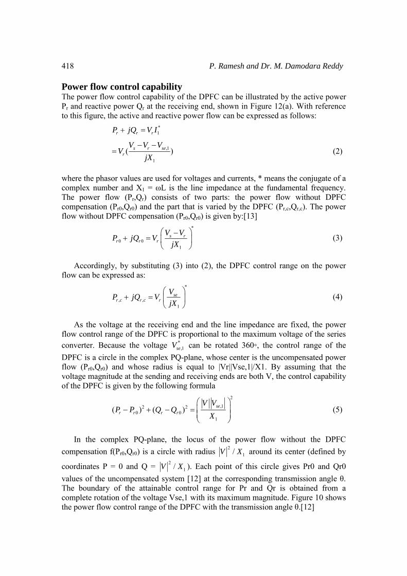
Power flow control capability The power flow control capability of the DPFC can be illustrated by the active power Pr and reactive power Qr at the receiving end, shown in Figure 12(a). With reference to this figure, the active and reactive power flow can be expressed as follows:
*1r r rP jQ V I+ =
,1
1
( )s r ser
V V VV
jX
− −= (2)
where the phasor values are used for voltages and currents, * means the conjugate of a complex number and X1 = ωL is the line impedance at the fundamental frequency. The power flow (Pr,Qr) consists of two parts: the power flow without DPFC compensation (Pr0,Qr0) and the part that is varied by the DPFC (Pr,c,Qr,c). The power flow without DPFC compensation (Pr0,Qr0) is given by:[13]
*
0 01
s rr r r
V VP jQ V
jX
⎛ ⎞−+ = ⎜ ⎟
⎝ ⎠ (3)
Accordingly, by substituting (3) into (2), the DPFC control range on the power flow can be expressed as:
*
, ,1
ser c r c r
VP jQ V
jX
⎛ ⎞+ = ⎜ ⎟
⎝ ⎠ (4)
As the voltage at the receiving end and the line impedance are fixed, the power flow control range of the DPFC is proportional to the maximum voltage of the series converter. Because the voltage *
,1seV can be rotated 360, the control range of the DPFC is a circle in the complex PQ-plane, whose center is the uncompensated power flow (Pr0,Qr0) and whose radius is equal to |Vr||Vse,1|/X1. By assuming that the voltage magnitude at the sending and receiving ends are both V, the control capability of the DPFC is given by the following formula
2
,12 20 0
1
( ) ( ) se
r r r r
V VP P Q Q
X
⎛ ⎞− + − = ⎜ ⎟
⎜ ⎟⎝ ⎠
(5)
In the complex PQ-plane, the locus of the power flow without the DPFC compensation f(Pr0,Qr0) is a circle with radius 2
1/V X around its center (defined by
coordinates P = 0 and Q = 21/V X ). Each point of this circle gives Pr0 and Qr0
values of the uncompensated system [12] at the corresponding transmission angle θ. The boundary of the attainable control range for Pr and Qr is obtained from a complete rotation of the voltage Vse,1 with its maximum magnitude. Figure 10 shows the power flow control range of the DPFC with the transmission angle θ.[12]
Control of Power in a Tra
Figure 10: DPFC active anθ.
Figure 11: Relationship b
Figure 12: Maximu
ansmission Line
nd reactive power control range with the tran
between Pse,1 and the power flow at the recei
um active power requirement of the series con
419
nsmission angle
ving end
nverters.

420
Figur
Simulation Results To simulate the effect oMATLAB. One shunt contested. The specifications o
ParameSendinReceivSeries Shunt cLine RLine inSourceSourceSeries Shunt c
Fig
P. Ramesh and Dr. M. Da
re 13: DPFC power-flow control range.
of the DPFC on Distributed system is pnverter and two single phase series converteof the DPFC in MATLAB are listed below.
eter Value ng end voltage (Vs) 200 V ving end voltage (Vr) 200 V converter voltage (Vse) 120 V converter voltage (Vsh) 120 V
Resistance (r) 0.3864 Ω/km nductance (L) 4.1264 mH/kme resistance (rs) 0.8929 Ω e Inductance (Ls) 16.58 mH capacitor (Cse) 1 μF capacitor (Csh ) 1 μF
gure 14: Simulation model of DPFC.
amodara Reddy
processed using ers are built and
Control of Power in a Tra
Figure
Figure 16: V
Fig.16 Consists of thinfluence the DPFC contro
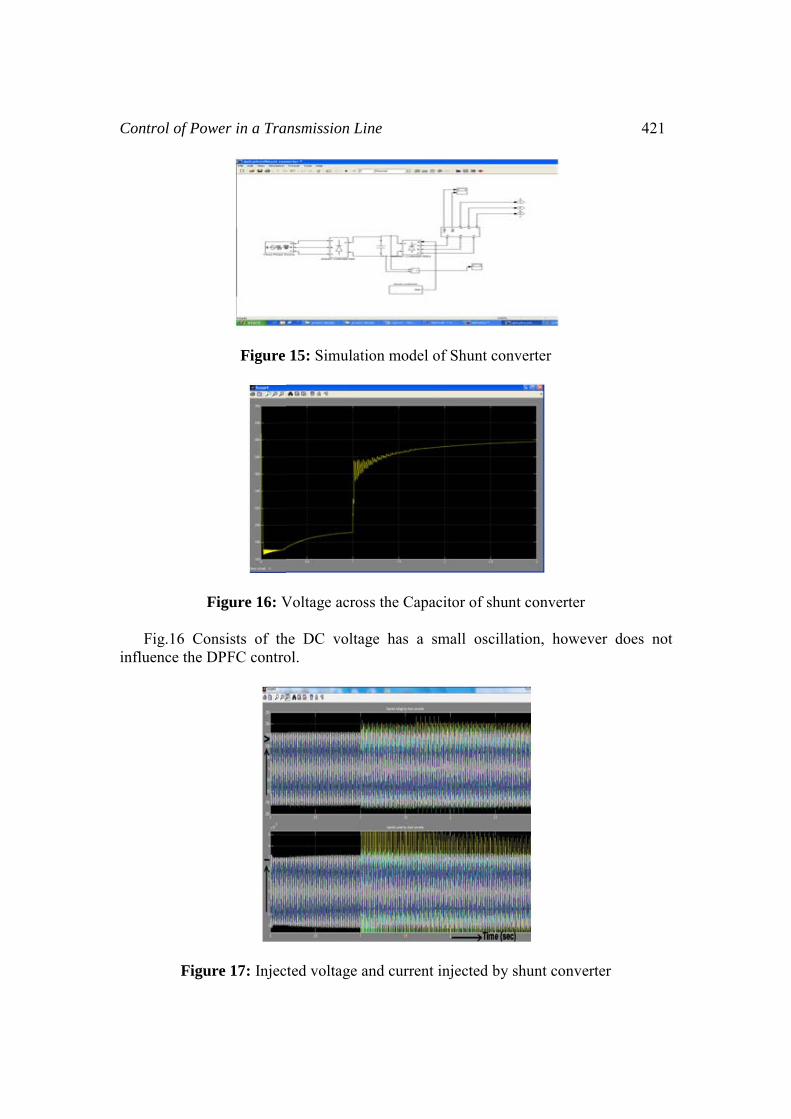
Figure 17: Injec
ansmission Line
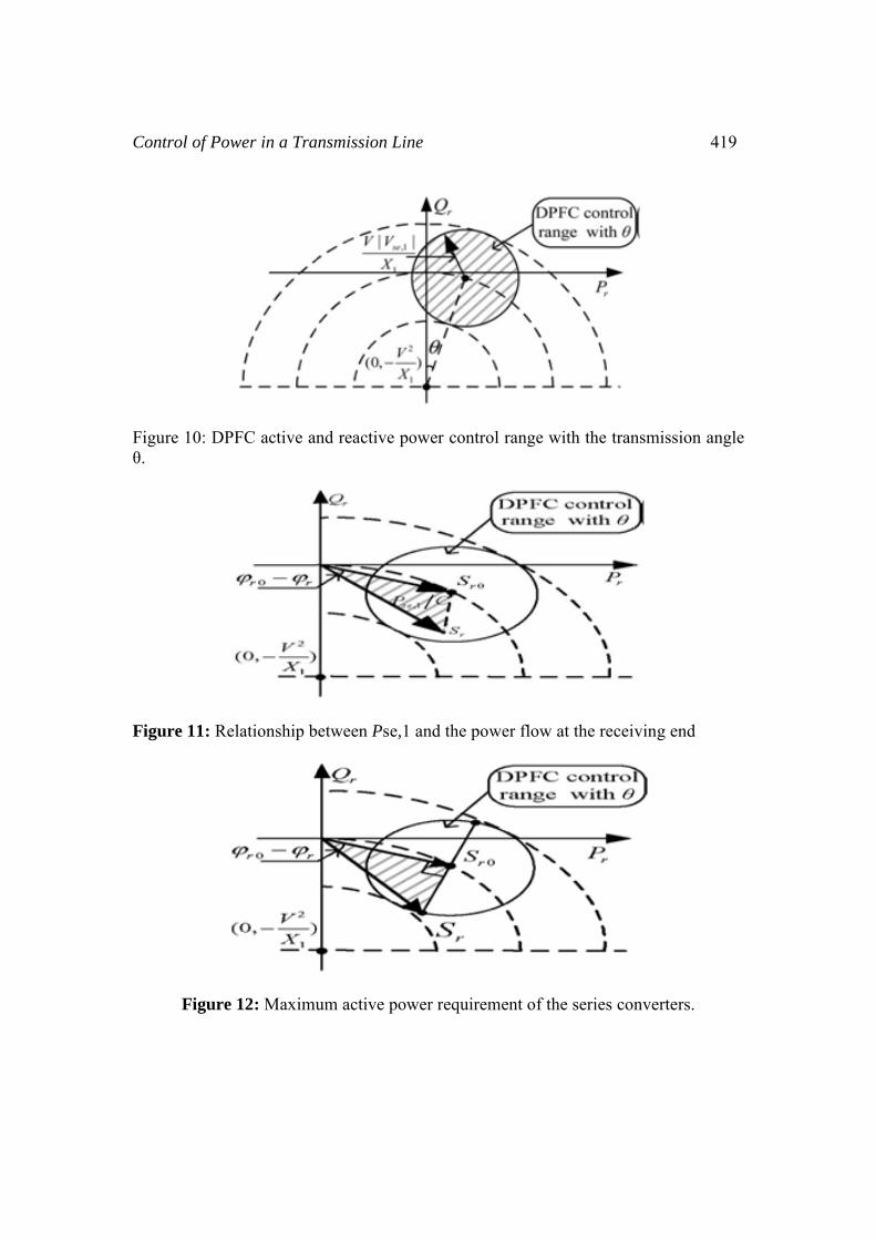
15: Simulation model of Shunt converter
Voltage across the Capacitor of shunt convert
he DC voltage has a small oscillation, howol.
cted voltage and current injected by shunt con
421
ter
wever does not
nverter

422
Figure
Fig.17 contains two frfrequency components. Tconverter is evenly dispervoltage and current.
Figure
Fig.19 contains two frfrequency components as by the series converter is efundamental voltage.
P. Ramesh and Dr. M. Da
18: Simulation model of Series converter
requency components ie., fundamental and TThe constant 3rd harmonic current injectedsed to the 3 phases and is superimposed on t
19: Injected Voltage by Series Converter
requency components i.e., fundamental and Tshown in Fig.4. The constant 3rd harmonic vevenly dispersed to the 3 phases and is super
amodara Reddy
Third harmonic d by the shunt the fundamental
Third harmonic voltage injected rimposed on the
Control of Power in a Tra
Figure
Figur
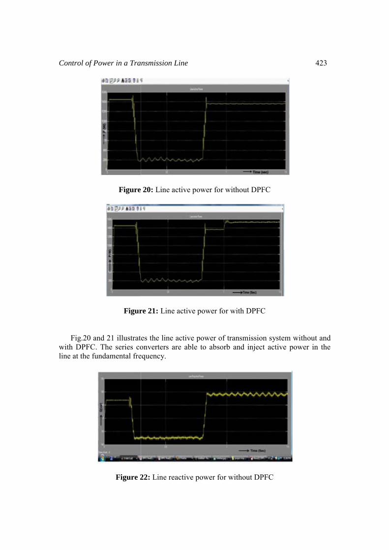
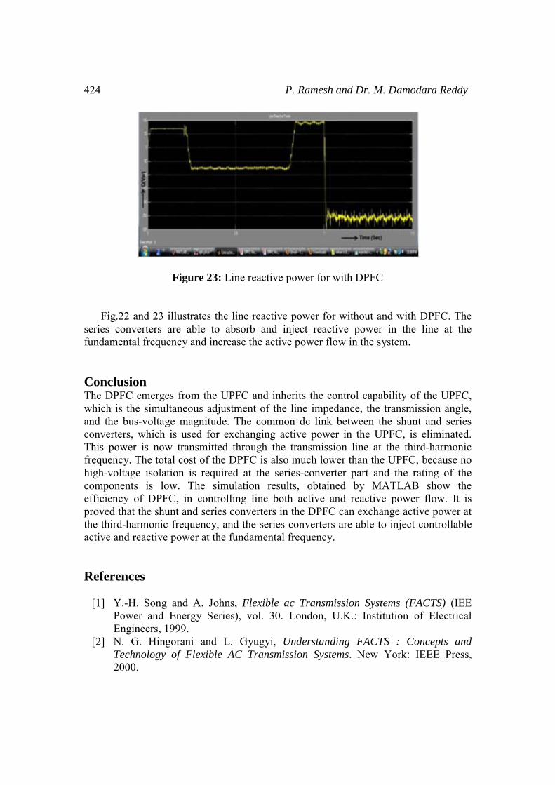
Fig.20 and 21 illustratwith DPFC. The series coline at the fundamental fre
Figure 2
ansmission Line
e 20: Line active power for without DPFC
re 21: Line active power for with DPFC
tes the line active power of transmission systeonverters are able to absorb and inject activequency.
22: Line reactive power for without DPFC
423
em without and ve power in the
424
Figure
Fig.22 and 23 illustratseries converters are ablfundamental frequency an Conclusion The DPFC emerges from which is the simultaneousand the bus-voltage magnconverters, which is usedThis power is now transmfrequency. The total cost ohigh-voltage isolation is components is low. Theefficiency of DPFC, in cproved that the shunt and the third-harmonic frequenactive and reactive power References
[1] Y.-H. Song and APower and EnergyEngineers, 1999.
[2] N. G. Hingorani Technology of Flex2000.
P. Ramesh and Dr. M. Da
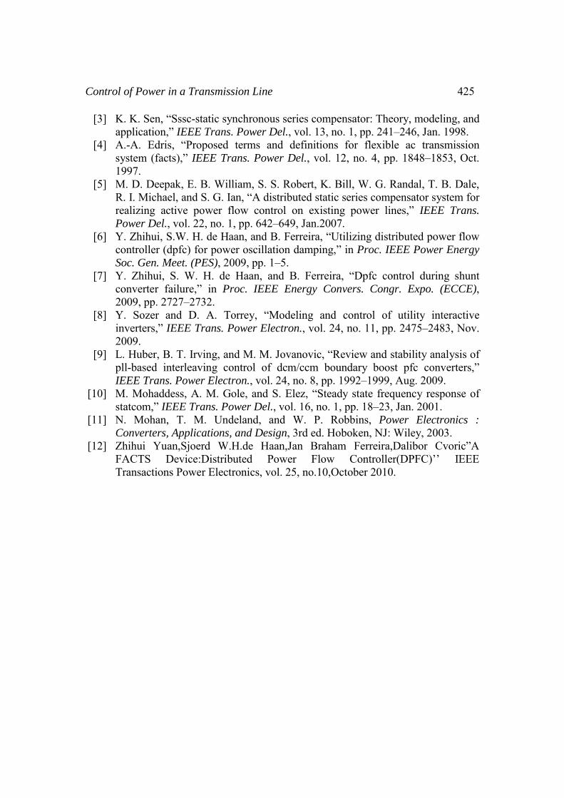
e 23: Line reactive power for with DPFC
tes the line reactive power for without and we to absorb and inject reactive power in
nd increase the active power flow in the system
the UPFC and inherits the control capabilitys adjustment of the line impedance, the trannitude. The common dc link between the shd for exchanging active power in the UPFCmitted through the transmission line at the of the DPFC is also much lower than the UPrequired at the series-converter part and the simulation results, obtained by MATL
controlling line both active and reactive poseries converters in the DPFC can exchange ncy, and the series converters are able to injat the fundamental frequency.
A. Johns, Flexible ac Transmission Systems y Series), vol. 30. London, U.K.: Institutio
and L. Gyugyi, Understanding FACTS : xible AC Transmission Systems. New York
amodara Reddy
with DPFC. The the line at the
m.
y of the UPFC, smission angle, hunt and series
C, is eliminated. third-harmonic
PFC, because no he rating of the LAB show the ower flow. It is
active power at ect controllable
(FACTS) (IEE on of Electrical
Concepts and k: IEEE Press,
Control of Power in a Transmission Line 425
[3] K. K. Sen, “Sssc-static synchronous series compensator: Theory, modeling, and application,” IEEE Trans. Power Del., vol. 13, no. 1, pp. 241–246, Jan. 1998.
[4] A.-A. Edris, “Proposed terms and definitions for flexible ac transmission system (facts),” IEEE Trans. Power Del., vol. 12, no. 4, pp. 1848–1853, Oct. 1997.
[5] M. D. Deepak, E. B. William, S. S. Robert, K. Bill, W. G. Randal, T. B. Dale, R. I. Michael, and S. G. Ian, “A distributed static series compensator system for realizing active power flow control on existing power lines,” IEEE Trans. Power Del., vol. 22, no. 1, pp. 642–649, Jan.2007.
[6] Y. Zhihui, S.W. H. de Haan, and B. Ferreira, “Utilizing distributed power flow controller (dpfc) for power oscillation damping,” in Proc. IEEE Power Energy Soc. Gen. Meet. (PES), 2009, pp. 1–5.
[7] Y. Zhihui, S. W. H. de Haan, and B. Ferreira, “Dpfc control during shunt converter failure,” in Proc. IEEE Energy Convers. Congr. Expo. (ECCE), 2009, pp. 2727–2732.
[8] Y. Sozer and D. A. Torrey, “Modeling and control of utility interactive inverters,” IEEE Trans. Power Electron., vol. 24, no. 11, pp. 2475–2483, Nov. 2009.
[9] L. Huber, B. T. Irving, and M. M. Jovanovic, “Review and stability analysis of pll-based interleaving control of dcm/ccm boundary boost pfc converters,” IEEE Trans. Power Electron., vol. 24, no. 8, pp. 1992–1999, Aug. 2009.
[10] M. Mohaddess, A. M. Gole, and S. Elez, “Steady state frequency response of statcom,” IEEE Trans. Power Del., vol. 16, no. 1, pp. 18–23, Jan. 2001.
[11] N. Mohan, T. M. Undeland, and W. P. Robbins, Power Electronics : Converters, Applications, and Design, 3rd ed. Hoboken, NJ: Wiley, 2003.
[12] Zhihui Yuan,Sjoerd W.H.de Haan,Jan Braham Ferreira,Dalibor Cvoric”A FACTS Device:Distributed Power Flow Controller(DPFC)’’ IEEE Transactions Power Electronics, vol. 25, no.10,October 2010.