Computation of the inviscid drift force caused by ... drift force may be caused on submerged bodies...
7
Inter J Nav Archit Oc Engng (2011) 3:201~207 http://dx.doi.org/10.2478/IJNAOE-2013-0063 ⓒSNAK, 2011 Computation of the inviscid drift force caused by nonlinear waves on a submerged circular cylinder Hyeok-Jun Koh 1 and Il-Hyoung Cho 2 1 Multidisciplinary Graduate School for Wind Energy, Jeju National University, Jeju, Korea 2 Department of Ocean System Engineering, Jeju National University, Jeju, Korea ABSTRACT: In this paper, we focused on computing the higher-harmonic components of the transmitted wave passing over a submerged circular cylinder to show that it is causing a horizontal negative drift force. As numerical models, a circular cylinder held fixed under free surface in deep water is adopted. As the submergence of a circular cylinder decreases and the incident wavelength becomes longer, the higher-harmonic components of the transmitted wave starts to increase. An increase of the higher-harmonic components of the transmitted wave makes the horizontal drift force be negative. It is also found that the higher-harmonic amplitudes averaged over the transmitted wave region become larger with the increase of wave steepness and wavelength as well as the decrease of submergence depth. KEY WORDS: Higher-harmonic component; Numerical wave tank; Drift force; Fully nonlinear potential flow; Transmitted wave. INTRODUCTION According to potential flow theory and the so-called d’Alembert paradox, there is no force acting on a submerged body in a steady state irrotational flow of an inviscid incompressible fluid. In such a case, only a viscous drag force can occur. For unsteady potential flows, such as caused by waves, however, a mean drift force can be induced on a submerged body. In particular, it has been long known that a negative drift force may be caused on submerged bodies by surface gravity waves of sufficient steepness, i.e., nonlinearity; hence, this wave-induced drift force is due to higher-order effects. Using conformal mapping, Dean (1948) thus found that a submerged circular cylinder does not reflect waves to leading order of steepness. Ursell (1950) confirmed this result by deriving the complete linear solution using a multipole expansion method. Following Ursell’s approach and estimating second-order effects from linear results, Ogilvie (1963) showed the existence of a mean second-order vertical force, but found that the horizontal mean force vanished to second-order. Using a Stokes expansion, Vada (1987) solved the second-order diffraction problem in the frequency-domain, but could not calculate all the terms of the mean horizontal force. Longuet-Higgins (1977) observed in experiment that a freely moving, neutrally buoyant, submerged cylinder experienced a negative drift force, causing it to move towards the wavemaker. He attributed this force mostly to wave breaking and, to a lesser degree, to the second-harmonic component of the transmitted wave. This conclusion, however, is not corroborated by Miyata et al. (1988) and Inoue and Kyozuka (1984) measurements, who both found that, as the cylinder was moved closer to the free surface, causing more intense wave breaking, the negative horizontal drift force was actually reduced and ultimately even changed sign. A number of two-dimensional, fully-nonlinear, inviscid time-domain computations have been proposed, to estimate strongly nonlinear effects caused by waves passing over submerged bodies of small equivalent diameter but large dimension in the transverse direction, with respect to wavelength, such as pipelines. Using the mixed Eulerian- Lagrangian method, Cointe (1989) calculated higher-order harmonic forces and wave transmission coefficients on a submerged cylinder, in a fully-nonlinear potential flow model, but did not calculate the horizontal drift force. Torum and Gudmestad (1990) computed particle trajectories and Lagrangian transport caused by steep waves, represented by exact streamfunction Stokes waves, over a submerged cylinder, in a space-periodic version of Grilli et al. (1989) fully- nonlinear potential flow model. Liu et al. (1992) applied the Higher-Order Spectral Method (HOS) to this problem and compared computations with analytical results and experimental observations. They also used exact deep-water Stokes waves as initial conditions and specified periodic conditions for upstream and downstream boundaries, Corresponding author: Il-Hyoung Cho e-mail: [email protected] Copyright © 2011 Society of Naval Architects of Korea. Production and hosting by ELSEVIER B.V. This is an open access article under the CC BY-NC 3.0 license ( http://creativecommons.org/licenses/by-nc/3.0/ ).
Transcript of Computation of the inviscid drift force caused by ... drift force may be caused on submerged bodies...
Inter J Nav Archit Oc Engng (2011) 3:201~207 http://dx.doi.org/10.2478/IJNAOE-2013-0063
ⓒSNAK, 2011
Computation of the inviscid drift force caused by nonlinear waves on a submerged circular cylinder
Hyeok-Jun Koh1 and Il-Hyoung Cho2
1Multidisciplinary Graduate School for Wind Energy, Jeju National University, Jeju, Korea 2Department of Ocean System Engineering, Jeju National University, Jeju, Korea
ABSTRACT: In this paper, we focused on computing the higher-harmonic components of the transmitted wave passing over a submerged circular cylinder to show that it is causing a horizontal negative drift force. As numerical models, a circular cylinder held fixed under free surface in deep water is adopted. As the submergence of a circular cylinder decreases and the incident wavelength becomes longer, the higher-harmonic components of the transmitted wave starts to increase. An increase of the higher-harmonic components of the transmitted wave makes the horizontal drift force be negative. It is also found that the higher-harmonic amplitudes averaged over the transmitted wave region become larger with the increase of wave steepness and wavelength as well as the decrease of submergence depth. KEY WORDS: Higher-harmonic component; Numerical wave tank; Drift force; Fully nonlinear potential flow; Transmitted wave. INTRODUCTION
According to potential flow theory and the so-called d’Alembert paradox, there is no force acting on a submerged body in a steady state irrotational flow of an inviscid incompressible fluid. In such a case, only a viscous drag force can occur. For unsteady potential flows, such as caused by waves, however, a mean drift force can be induced on a submerged body. In particular, it has been long known that a negative drift force may be caused on submerged bodies by surface gravity waves of sufficient steepness, i.e., nonlinearity; hence, this wave-induced drift force is due to higher-order effects. Using conformal mapping, Dean (1948) thus found that a submerged circular cylinder does not reflect waves to leading order of steepness. Ursell (1950) confirmed this result by deriving the complete linear solution using a multipole expansion method. Following Ursell’s approach and estimating second-order effects from linear results, Ogilvie (1963) showed the existence of a mean second-order vertical force, but found that the horizontal mean force vanished to second-order. Using a Stokes expansion, Vada (1987) solved the second-order diffraction problem in the frequency-domain, but could not calculate all the terms of the mean horizontal force. Longuet-Higgins (1977) observed in experiment that a freely moving, neutrally buoyant, submerged cylinder experienced a negative drift force,
causing it to move towards the wavemaker. He attributed this force mostly to wave breaking and, to a lesser degree, to the second-harmonic component of the transmitted wave. This conclusion, however, is not corroborated by Miyata et al. (1988) and Inoue and Kyozuka (1984) measurements, who both found that, as the cylinder was moved closer to the free surface, causing more intense wave breaking, the negative horizontal drift force was actually reduced and ultimately even changed sign.
A number of two-dimensional, fully-nonlinear, inviscid time-domain computations have been proposed, to estimate strongly nonlinear effects caused by waves passing over submerged bodies of small equivalent diameter but large dimension in the transverse direction, with respect to wavelength, such as pipelines. Using the mixed Eulerian-Lagrangian method, Cointe (1989) calculated higher-order harmonic forces and wave transmission coefficients on a submerged cylinder, in a fully-nonlinear potential flow model, but did not calculate the horizontal drift force. Torum and Gudmestad (1990) computed particle trajectories and Lagrangian transport caused by steep waves, represented by exact streamfunction Stokes waves, over a submerged cylinder, in a space-periodic version of Grilli et al. (1989) fully-nonlinear potential flow model. Liu et al. (1992) applied the Higher-Order Spectral Method (HOS) to this problem and compared computations with analytical results and experimental observations. They also used exact deep-water Stokes waves as initial conditions and specified periodic conditions for upstream and downstream boundaries,
Corresponding author: Il-Hyoung Cho e-mail: [email protected]
Copyright © 2011 Society of Naval Architects of Korea. Production and hosting by ELSEVIER B.V. This is an open access article under the CC BY-NC 3.0 license
( http://creativecommons.org/licenses/by-nc/3.0/ ).
202 Inter J Nav Archit Oc Engng (2011) 3:201~207
a requirement of the HOS method. In this paper, we establish the origin of the negative drift
force caused by steep waves on a submerged cylinder, by similarly performing two-dimensional (2D) Fully Nonlinear Potential Flow (FNPF) simulations in the time domain. In the simulations, we use the most recent version of the model originally developed by Grilli et al. (1989), with improvements and additions by Grilli and Subramanya (1996) and Grilli and Horrillo (1997) (hereafter referred to as 2D-FNPF model). Unlike earlier studies, our computations are not space-periodic but feature the generation of exact fully nonlinear periodic incident waves at one extremity of a “Numerical Wave Tank” (NWT), as well as wave absorption/radiation at the other extremity. Although our model can simulate overturning waves, we did not consider wave breaking effects in this paper. For non-breaking waves, we will show that the higher-harmonic components of the transmitted wave are the main cause for the negative horizontal drift force on a submerged body. Numerical results will also show that the magnitude of this higher-harmonic components increases as the body submergence decreases, and incident wavelength and steepness increase. NEGATIVE DRIFT FORCE
To establish the relationship between horizontal drift force and higher-harmonic components of the transmitted waves passing over a submerged body, it is useful to first obtain a simple estimate of the solution based on the conservation of energy and linear horizontal momentum. Assuming wave reflection by a submerged circular to be negligible and considering the incident and transmitted wave amplitudes on the downstream up/down sides of a submerged cylinder, let an , bn be the n-th harmonics of the incident and transmitted wave amplitudes, respectively. With this assumption, application of the conservation of horizontal momentum gives an expression for the horizontal drift force to leading order, as,
2 2
14x n nn
gD a b
(1)
From conservation of energy, an and bn are related by,
2 2
1 1
n n
n n
a b
n n
(2)
Since, for periodic incident waves, the amplitude of the
first harmonic a1 is much greater than all other harmonic amplitudes, we can neglect all an , n > 1 term in Eqs. 1 and 2. From Eqs. 1 and 2, we can obtain
Eq. 3 provides a way to estimate Dx for given transmitted wave harmonic amplitudes, and is a generalization of the result of Longuet-Higgins (1977), who only considered the first (b2) term only. Although it only represents an approximation valid
for small incident wave steepness, Eq. 3 indicates that the horizontal force is always negative, with a magnitude that increases with the degree of higher-harmonic generation.
2
2
1
4x nn
g nD b
n
(3)
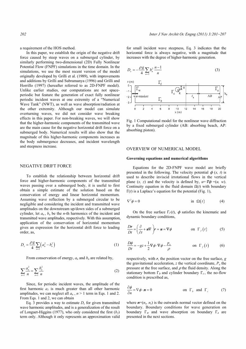
Fig. 1 Computational model for the nonlinear wave diffraction by a fixed submerged cylinder (AB: absorbing beach, AP: absorbing piston). OVERVIEW OF NUMERICAL MODEL Governing equations and numerical algorithms
Equations for the 2D-FNPF wave model are briefly presented in the following. The velocity potential ϕ (x, t) is used to describe inviscid irrotational flows in the vertical plane (x, z) and the velocity is defined by, u= ϕ=(u, w). Continuity equation in the fluid domain Ω(t) with boundary Γ(t) is a Laplace’s equation for the potential (Fig. 1),
2 0 in t (4)
On the free surface Γf(t), ϕ satisfies the kinematic and
dynamic boundary conditions, D
Dt t
ru r u on f t (5)
1
2apD
gzDt
on f t (6)
respectively, with r, the position vector on the free surface, g the gravitational acceleration, z the vertical coordinate, Pa the pressure at the free surface, and ρ the fluid density. Along the stationary bottom Γb and cylinder boundary Γc, the no-flow condition is prescribed as,
0n
n on b and c (7)
where n=(nx, nz) is the outwards normal vector defined on the boundary. Boundary conditions for wave generation on boundary Γw and wave absorption on boundary Γa are presented in the next sections.
Inter J Nav Archit Oc Engng (2011) 3:201~207 203
Eq. 4 is transformed into a Boundary Integral Equation (BIE), using Green’s 2nd identity, and solved by a BEM. The BIE is evaluated at N discretization nodes on the boundary and M higher-order elements are defined to interpolate in between discretization nodes. In the present applications, quadratic isoparametric elements are used on lateral and bottom boundaries, and cubic elements ensuring continuity of the boundary slope are used on the free surface. Expressions of BEM integrals (regular, singular, quasi-singular) for these elements are given in Grilli et al. (1989) and Grilli and Subramanya (1996).
Free surface boundary conditions (5) and (6) are time integrated based on second-order Taylor series expansions expressed in terms of a time step Δt and of the Lagrangian time derivative, D/Dt, for ϕ and r. First-order coefficients in the series correspond to free surface conditions (5) and (6), in which ϕ and ∂ϕ/∂n are obtained from the BEM solution of the BIE at time t. Second-order coefficients are expressed as D/Dt of Eqs. 5 and 6, and are calculated using the solution of a second BIE for (∂ϕ/∂t, ∂2ϕ/∂t∂t), for which boundary conditions are obtained from the solution of the first problem. Detailed expressions for the Taylor series are given in Grilli et al. (1989).
At each time step, global accuracy of computations is verified by computing errors in total volume and energy for the generated wave train. Earlier work showed that these errors are function of both the size (i.e., distance between nodes) and the degree (i.e., quadratic, cubic,...) of boundary elements used in the spatial discretization, and of the size of the selected time step. This led to adaptively selecting the optimal time step, based on a mesh Courant number C0(t), which for cubic elements has an optimum value of 0.40. This value is used in the present applications. Exact periodic wave generation in the model
We use the method developed by Grilli and Horrillo (1997) to generate “numerically exact” periodic wave solutions of the FNPF problem in the model (i.e., which will propagate over constant depth without change of form). “Streamfunction Wave Theory” (SFW) is first used to calculate wave shape and kinematics, for given height H and period T, in water of depth h, and the particle velocity and acceleration of these SFWs is specified along a vertical “wavemaking” boundary (Γw).
Since free surface discretization nodes represent fluid particles, during computations, they gradually drift away in the direction of the mean mass transport, eventually leading to a poor resolution close to Γw. This drift is cancelled by horizontally moving Γw with the Lagrangian motion of the first node/particle on the free surface. Similarly, to prevent fluid from accumulating in the computational domain, because of the mean wave mass transport, incident SFWs are generated over a uniform current U, equal and opposite to their mean mass transport velocity. Such waves are referred to as “zero-mass-flux” SFWs. Since a current slightly modifies wave characteristics due to Doppler effect, U is iteratively calculated, for specified wave characteristics as part of the SFW solution. See details in Grilli and Horrillo (1997).
Wave energy absorption in the model
To prevent spurious wave reflection in the model, following Grilli and Horrillo (1997), an absorbing beach region (AB) is specified at the far end extremity of the computational domain (Fig. 1). The AB combines an “absorbing pressure” term Pa=P in the dynamic free surface condition (6), and an actively absorbing piston condition (AP) on vertical boundary Γa. To always induce energy dissipation, the absorbing pressure P is specified as opposite and proportional to the normal particle velocity on the free surface, with a gentle ramp-up over a short distance in front of the AB. Grilli and Horrillo (1997) showed that the AB is efficient in absorbing higher-frequency waves if its length is at least twice the dominant wavelength. To better radiate lower frequency waves out of the computational domain, an AP is specified, that, following Grilli and Horrillo (1997), moves proportionally to the mean instantaneous dynamic wave force.
Details of the AB and AP implementation and validation can be found in Grilli and Horrillo (1997), and their application to nonlinear wave shoaling, e.g., in Grilli (1998) and Grilli and Horillo (1999). NUMERICAL APPLICATIONS
Fig. 1 shows the NWT computational domain used in this application, with a submerged circular cylinder located at mid-length of the tank. Exact periodic SFWs (with zero mean mass flux) are generated on the wavemaking boundary, as detailed before, and waves are dissipated both in the absorbing beach AB (of fixed length 5m) and using the absorbing piston AP. The computational domain is 20m long, with constant water depth h=3m. The boundary is discretized with N=310 nodes M=227 elements, with Nb=60 nodes discretizing the cylinder boundary, and Nf =150 nodes on the free surface. Initial spacing between nodes on the free surface is thus Δx0 = 0.134m. The nodal points on the free surface are regridded every 20 time steps.
We denote by R(=0.25m) the radius of the circular cylinder, and by H its submergence depth, measured from z=0 to the cylinder axis. Wave period is specified such as to achieve deep water conditions in the tank. The transmission coefficient for the n-th harmonic is defined as Tn=bn/A, where A is the incident wave amplitude and bn the amplitude of the n-th transmitted wave harmonic, defined at the location x=15m, which marks the starting point of the absorbing beach.
Computations are performed for incident waves of steepness varying in the range 0.01 kA 0.1 and length within 0.3 kR 0.6. This yields a maximum wavelength L=5.24m, such that L/h0=1.75, which is clearly a deep water wave. The cylinder submergence depth varies within 1.5 H/R 2.2. Results will show the dependence of the wave transmission coefficient, drift force, and oscillating force on parameters (kA, kR, H/R).
In each simulation, the horizontal drift forces, averaged over time τ, are calculated as,
204 Inter J Nav Archit Oc Engng (2011) 3:201~207
0
0
1d
t
x xtD F t t
(8)
where dc
x D xF p n
, is the time-dependent horizontal
dynamic wave force on the submerged cylinder of boundary
Γc, with / 1/ 2 ,Dp p gz t the
dynamic pressure (readily available on the cylinder boundary Γc for each time step of NWT computations), and Dx is positive in the direction of the incident wave propagation. The horizontal forces corresponding to the n-th harmonic can be obtained from the Fourier transform (n=1,2,…),
0
0
1d
tn i n tx xt
F F t e t
(9)
where T=2π/ω is the incident wave period (or first harmonic period for n=1). The time interval τ for the averaging is set to 10T, and t0 is selected large enough so that quasi-steady state is reached in the computations.
In each simulation, harmonic analyses are also made, for the surface elevations computed at many successive “numerical wave gauges” equally spaced around the submerged cylinder. Results will show that free higher-harmonics are generated in transmitted waves.
Using the present NWT, the time-averaged spatial variation of amplitudes of the first three harmonic of transmitted waves, are calculated from Fourier transforms as (for n=1,2,3),
0
0
1, d
t i n tn t
b x x t e t
(10)
Spatially-averaged values of these harmonic amplitudes
are then obtained as,
0
1 d
gl
n ng
b b x xl
(11)
where lg is the length of the higher-harmonic wave generation region, defined in the NWT between 12 and 15m (the beginning of the AB; see Fig. 1).
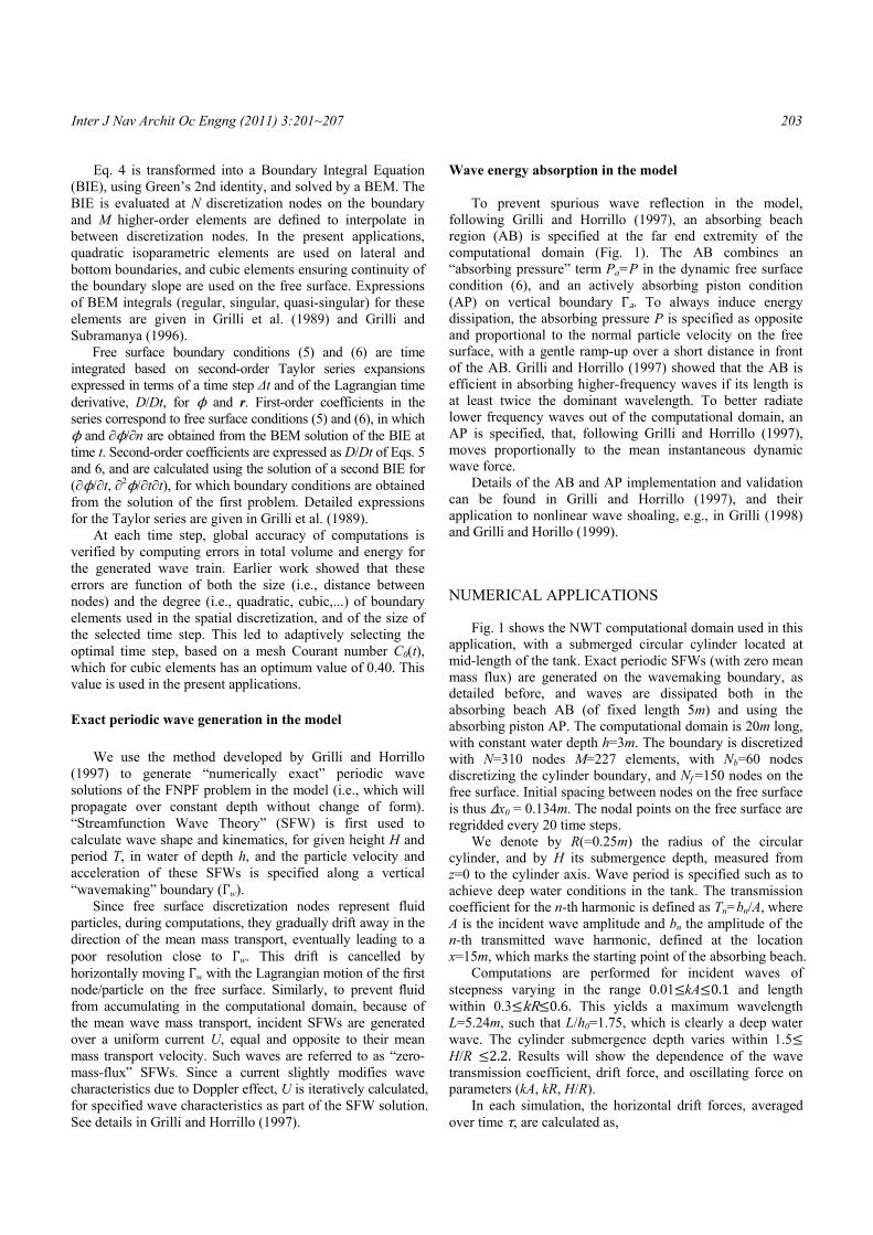
As indicated before, this NWT has been validated, both numerically and experimentally, for many different types of incident waves and their interactions with obstacles or the bottom. Here, we verify the accuracy of computations by calculating numerical errors on volume conservation and continuity (boundary fluxes) in Fig. 2, for a typical case with kA=0.08, kR=0.4, H/R=1.5. We see, both of these errors oscillate in time, but remain very small during a typical computation. While the continuity error εr is instantaneous and thus indicates the relative accuracy of the BEM solution in the NWT at a given time (a very small O(10-9)), the volume error εr integrates over time errors due to both spatial discretization and time stepping, as well as effects of the AB (and is thus larger at O(10-6)).
Fig. 2 Volume change error εv=(V(t)-V0)/V0 and continuity error εr=(∫Γ ∂ϕ/∂n dΓ)Δt/V during computations for kA=0.08, kR=0.4, H/R=1.5, NF/Nw=30.
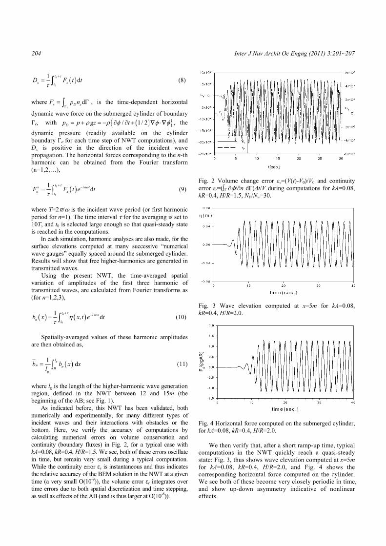
Fig. 3 Wave elevation computed at x=5m for kA=0.08, kR=0.4, H/R=2.0.
Fig. 4 Horizontal force computed on the submerged cylinder, for kA=0.08, kR=0.4, H/R=2.0.
We then verify that, after a short ramp-up time, typical
computations in the NWT quickly reach a quasi-steady state: Fig. 3, thus shows wave elevation computed at x=5m for kA=0.08, kR=0.4, H/R=2.0, and Fig. 4 shows the corresponding horizontal force computed on the cylinder. We see both of these become very closely periodic in time, and show up-down asymmetry indicative of nonlinear effects.
Inter J Nav Archit Oc Engng (2011) 3:201~207 205
Finally, the convergence of NWT computations with free surface discretization is demonstrated in Table 1, for kA=0.08, kR=0.4, H/R=1.5. [Note, in Table 1, Nw is the number of nodes per wavelength.] As the number of nodes increases (corresponding to a doubling, tripling and quadrupling of number of nodes per wavelength), the time averaged horizontal drift force and 1st and 2nd harmonic forces clearly converge. Due to the very small changes between the last two values, Nf=150(Nw=30) is selected for all computations and deemed to provide sufficient accuracy and resolution of computations. Table 1 Convergence of horizontal drift force on cylinder, and first and second harmonic forces, with the number of free surface BEM nodes Nf, for kA=0.08, kR=0.4, H/R=1.5. [Note, Nw denotes the number of nodes per incident wavelength.]
Nf Nw Dx/(ρgA2) Fx1/(ρgRA) Fx
2/( ρgA2) 50 10 -0.0851 1.4318 0.8130
100 20 -0.0927 1.4911 0.8935
150 30 -0.1027 1.5055 0.9437 200 40 -0.1052 1.5026 0.9386
Fig. 5 Computed first(T1) and second(T2) harmonic wave transmission coefficients as a function of incident wave steepness (-●-), for kR=0.4, H/R=1.5. Experimental results of Grue (1991) are denoted by symbols ◊ and 4th-order numerical HOS results of Liu et al. (1992) by ○.
Fig. 6 Same results as in Fig. 5, as a function of cylinder submergence (-●-), for kR=0.4, kA=0.08.
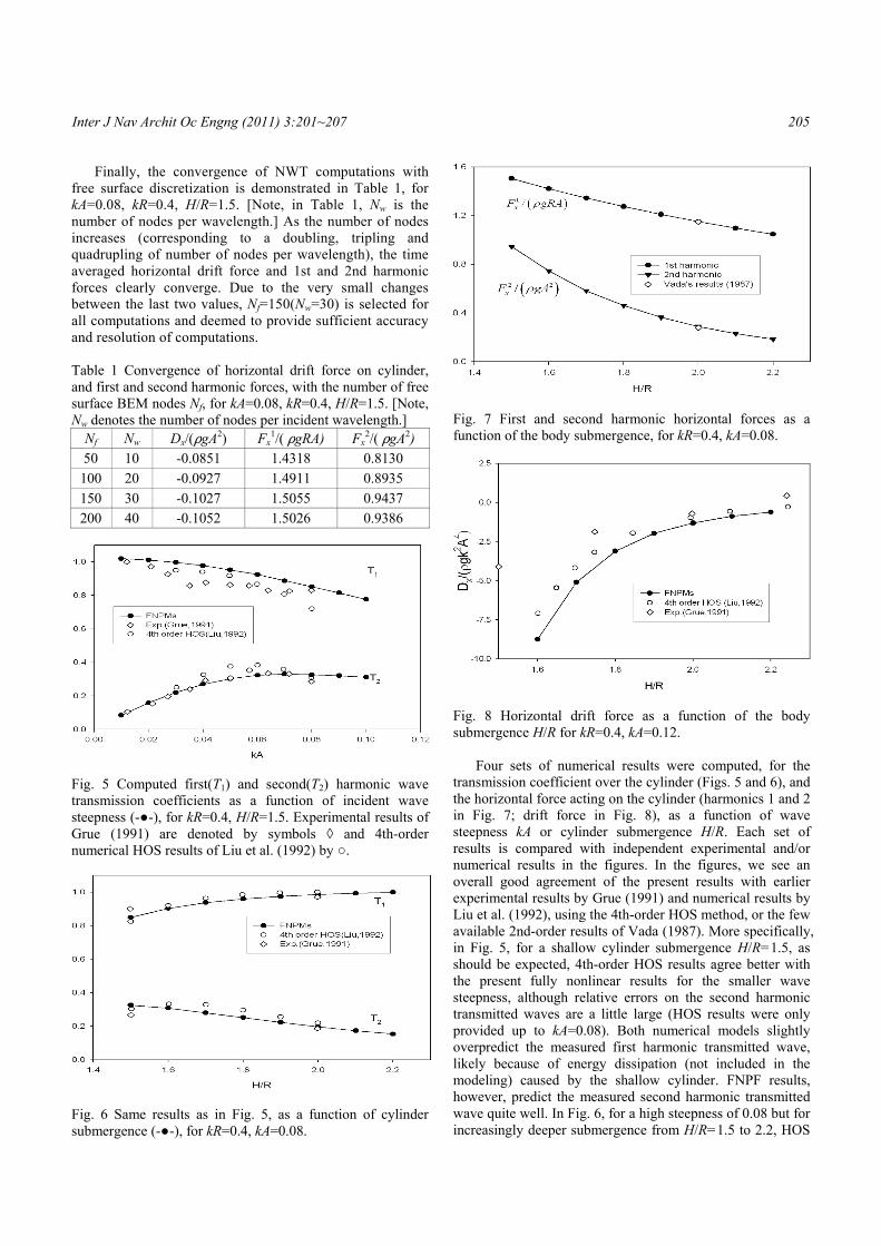
Fig. 7 First and second harmonic horizontal forces as a function of the body submergence, for kR=0.4, kA=0.08.
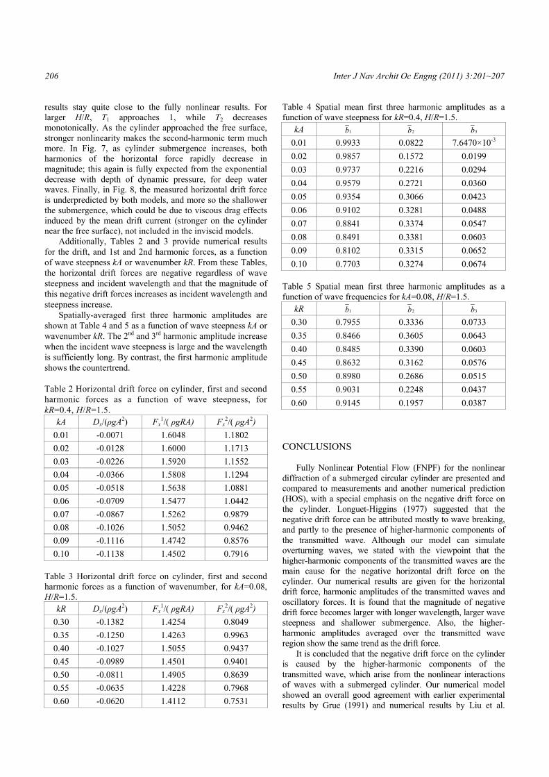
Fig. 8 Horizontal drift force as a function of the body submergence H/R for kR=0.4, kA=0.12.
Four sets of numerical results were computed, for the transmission coefficient over the cylinder (Figs. 5 and 6), and the horizontal force acting on the cylinder (harmonics 1 and 2 in Fig. 7; drift force in Fig. 8), as a function of wave steepness kA or cylinder submergence H/R. Each set of results is compared with independent experimental and/or numerical results in the figures. In the figures, we see an overall good agreement of the present results with earlier experimental results by Grue (1991) and numerical results by Liu et al. (1992), using the 4th-order HOS method, or the few available 2nd-order results of Vada (1987). More specifically, in Fig. 5, for a shallow cylinder submergence H/R=1.5, as should be expected, 4th-order HOS results agree better with the present fully nonlinear results for the smaller wave steepness, although relative errors on the second harmonic transmitted waves are a little large (HOS results were only provided up to kA=0.08). Both numerical models slightly overpredict the measured first harmonic transmitted wave, likely because of energy dissipation (not included in the modeling) caused by the shallow cylinder. FNPF results, however, predict the measured second harmonic transmitted wave quite well. In Fig. 6, for a high steepness of 0.08 but for increasingly deeper submergence from H/R=1.5 to 2.2, HOS
206 Inter J Nav Archit Oc Engng (2011) 3:201~207
results stay quite close to the fully nonlinear results. For larger H/R, T1 approaches 1, while T2 decreases monotonically. As the cylinder approached the free surface, stronger nonlinearity makes the second-harmonic term much more. In Fig. 7, as cylinder submergence increases, both harmonics of the horizontal force rapidly decrease in magnitude; this again is fully expected from the exponential decrease with depth of dynamic pressure, for deep water waves. Finally, in Fig. 8, the measured horizontal drift force is underpredicted by both models, and more so the shallower the submergence, which could be due to viscous drag effects induced by the mean drift current (stronger on the cylinder near the free surface), not included in the inviscid models.
Additionally, Tables 2 and 3 provide numerical results for the drift, and 1st and 2nd harmonic forces, as a function of wave steepness kA or wavenumber kR. From these Tables, the horizontal drift forces are negative regardless of wave steepness and incident wavelength and that the magnitude of this negative drift forces increases as incident wavelength and steepness increase.
Spatially-averaged first three harmonic amplitudes are shown at Table 4 and 5 as a function of wave steepness kA or wavenumber kR. The 2nd and 3rd harmonic amplitude increase when the incident wave steepness is large and the wavelength is sufficiently long. By contrast, the first harmonic amplitude shows the countertrend. Table 2 Horizontal drift force on cylinder, first and second harmonic forces as a function of wave steepness, for kR=0.4, H/R=1.5.
kA Dx/(ρgA2) Fx1/( ρgRA) Fx
2/( ρgA2)
0.01 -0.0071 1.6048 1.1802
0.02 -0.0128 1.6000 1.1713
0.03 -0.0226 1.5920 1.1552
0.04 -0.0366 1.5808 1.1294
0.05 -0.0518 1.5638 1.0881
0.06 -0.0709 1.5477 1.0442
0.07 -0.0867 1.5262 0.9879
0.08 -0.1026 1.5052 0.9462
0.09 -0.1116 1.4742 0.8576
0.10 -0.1138 1.4502 0.7916 Table 3 Horizontal drift force on cylinder, first and second harmonic forces as a function of wavenumber, for kA=0.08, H/R=1.5.
kR Dx/(ρgA2) Fx1/( ρgRA) Fx
2/( ρgA2)
0.30 -0.1382 1.4254 0.8049
0.35 -0.1250 1.4263 0.9963
0.40 -0.1027 1.5055 0.9437
0.45 -0.0989 1.4501 0.9401
0.50 -0.0811 1.4905 0.8639
0.55 -0.0635 1.4228 0.7968
0.60 -0.0620 1.4112 0.7531
Table 4 Spatial mean first three harmonic amplitudes as a function of wave steepness for kR=0.4, H/R=1.5.
kA 1b 2b 3b
0.01 0.9933 0.0822 7.6470×10⁻³
0.02 0.9857 0.1572 0.0199
0.03 0.9737 0.2216 0.0294
0.04 0.9579 0.2721 0.0360
0.05 0.9354 0.3066 0.0423
0.06 0.9102 0.3281 0.0488
0.07 0.8841 0.3374 0.0547
0.08 0.8491 0.3381 0.0603
0.09 0.8102 0.3315 0.0652
0.10 0.7703 0.3274 0.0674 Table 5 Spatial mean first three harmonic amplitudes as a function of wave frequencies for kA=0.08, H/R=1.5.
kR 1b 2b 3b
0.30 0.7955 0.3336 0.0733
0.35 0.8466 0.3605 0.0643
0.40 0.8485 0.3390 0.0603
0.45 0.8632 0.3162 0.0576
0.50 0.8980 0.2686 0.0515
0.55 0.9031 0.2248 0.0437
0.60 0.9145 0.1957 0.0387 CONCLUSIONS
Fully Nonlinear Potential Flow (FNPF) for the nonlinear diffraction of a submerged circular cylinder are presented and compared to measurements and another numerical prediction (HOS), with a special emphasis on the negative drift force on the cylinder. Longuet-Higgins (1977) suggested that the negative drift force can be attributed mostly to wave breaking, and partly to the presence of higher-harmonic components of the transmitted wave. Although our model can simulate overturning waves, we stated with the viewpoint that the higher-harmonic components of the transmitted waves are the main cause for the negative horizontal drift force on the cylinder. Our numerical results are given for the horizontal drift force, harmonic amplitudes of the transmitted waves and oscillatory forces. It is found that the magnitude of negative drift force becomes larger with longer wavelength, larger wave steepness and shallower submergence. Also, the higher-harmonic amplitudes averaged over the transmitted wave region show the same trend as the drift force.
It is concluded that the negative drift force on the cylinder is caused by the higher-harmonic components of the transmitted wave, which arise from the nonlinear interactions of waves with a submerged cylinder. Our numerical model showed an overall good agreement with earlier experimental results by Grue (1991) and numerical results by Liu et al.
Inter J Nav Archit Oc Engng (2011) 3:201~207 207
(1992), using the 4th-order HOS method and simulated the higher-harmonic generation due to nonlinear interactions of streamfunction wave by a submerged cylinder through a systematic parametric investigation with varying variables such as wave steepness, wavelength, and submergence. ACKNOWLEDGEMENTS
This work was supported by the New & Renewable Energy of the Korea Institute of Energy Technology Evaluation and Planning (KETEP) grant funded by the Korea government Ministry of Knowledge Economy. (2010302007 0080). REFERENCES Cointe, R., 1989. Nonlinear simulation of transient free
surface flows. In Proc. 5th Intl Conf. Num. Ship Hydro. Hiroshima. pp.239-250.
Dean, W.R., 1948. On the reflection of surface waves by a submerged circular cylinder. Proc. Camb. Phil. Soc. 44, pp.483-491.
Grilli, S.T. Skourup, J. and Svendsen, I.A., 1989. An Efficient Boundary Element Method for Nonlinear Water Waves. Engineering Analysis with Boundary Elements, 6(2), pp.97-107.
Grilli, S.T. and Subramanya, R., 1996. Numerical Modeling of Wave Breaking Induced by Fixed or Moving Boundaries. Computational Mechanics, 17(6), pp.374-391.
Grilli, S.T. and Horrillo, J., 1997. Numerical Generation and Absorption of Fully Nonlinear Periodic Waves. J. Engineering Mechanics, 123(10), pp.1060-1069.
Grilli, S.T., 1998. Depth Inversion in Shallow Water Based on Nonlinear Properties of Shoaling Periodic Waves. Coastal Engineering, 35(3), pp.185-209.
Grilli, S.T. and Horrillo, J., 1999. Shoaling of periodic waves over barred-beaches in a fully nonlinear numerical wave tank. Intl. J. Offshore and Polar Engng, 9(4), pp.257-263.
Grue, J., 1991. Nonlinear water waves at a submerged obstacle or bottom topography. Preprint Series of Institute of Mathmatics, University of Oslo. 2, pp.1-21.
Inoue, R. and Kyozuka, Y., 1984. On the nonlinear wave force acting on submerged cylinders. J. Soc. Nav. Arch. Japan, 156, pp.115-127.
Liu, Y. Dommermuth, D.G. and Yue, D.K.P., 1992. A higher-order spectral method for nonlinear wave-body interactions. J. Fluid Mech. 245, pp.115-136.
Longuet-Higgins, M.S., 1977. The mean forces exerted by waves on floating or submerged bodies with applications to sand bars and power machines. Proc. R. Soc. Lond. 352, pp.463-480.
Miyata, H. Khalil, G. Lee, Y.G. and Kanai, M., 1988. An experimental study of the nonlinear forces on horizontal cylinders. J. Kansai Soc. N.A. Japan, 209, pp.11-23.
Ogilvie, T.F., 1963. First and second order forces on a cylinder submerged under the free surface. J. Fluid Mech. 16, pp.451-472.
Torum, A. and Gudmestad, O.T., 1990. Water Wave Kinematics. Kluwer Academic Publishers: Boston. pp.297-312.
Ursell, F., 1950. Surface waves on deep water in the presence of a submerged circular cylinder. Proc. Camb. Phil. Soc., 46, I: pp.141-152, II: pp.153-158.
Vada, T., 1987. A numerical solution of the second-order wave diffraction problem for a submerged cylinder of arbitrary shape. J. Fluid Mech. 174, pp.23-37.