Single axis volumetric µPTV for wall shear stress estimation
1
Complex geology slope stability analysis by shear
strength reduction
Marek Cala, Jerzy FlisiakDepartment of Geomechanics, Civil Engineering & GeotechnicsAGH University of Science & Technology
Slope stability Shear strength reduction technique (SSR)
� The stability of slopes may be estimated using 2D limit equilibrium methods (LEM) or numerical methods.
� Due to the rapid development of computing efficiency, several numerical methods are gaining increasing popularity in slope stability engineering.
� The factor of safety (FS) of a soil slope is defined as the number by which the original shear strength parameters must be divided in order to bring the slope to the point of failure.
20Department of Geomechanics, Civil Engineering & Geotechnics
==
trialtrial
trialtrial FS
tgarctg
FS
cc
ϕϕ
2
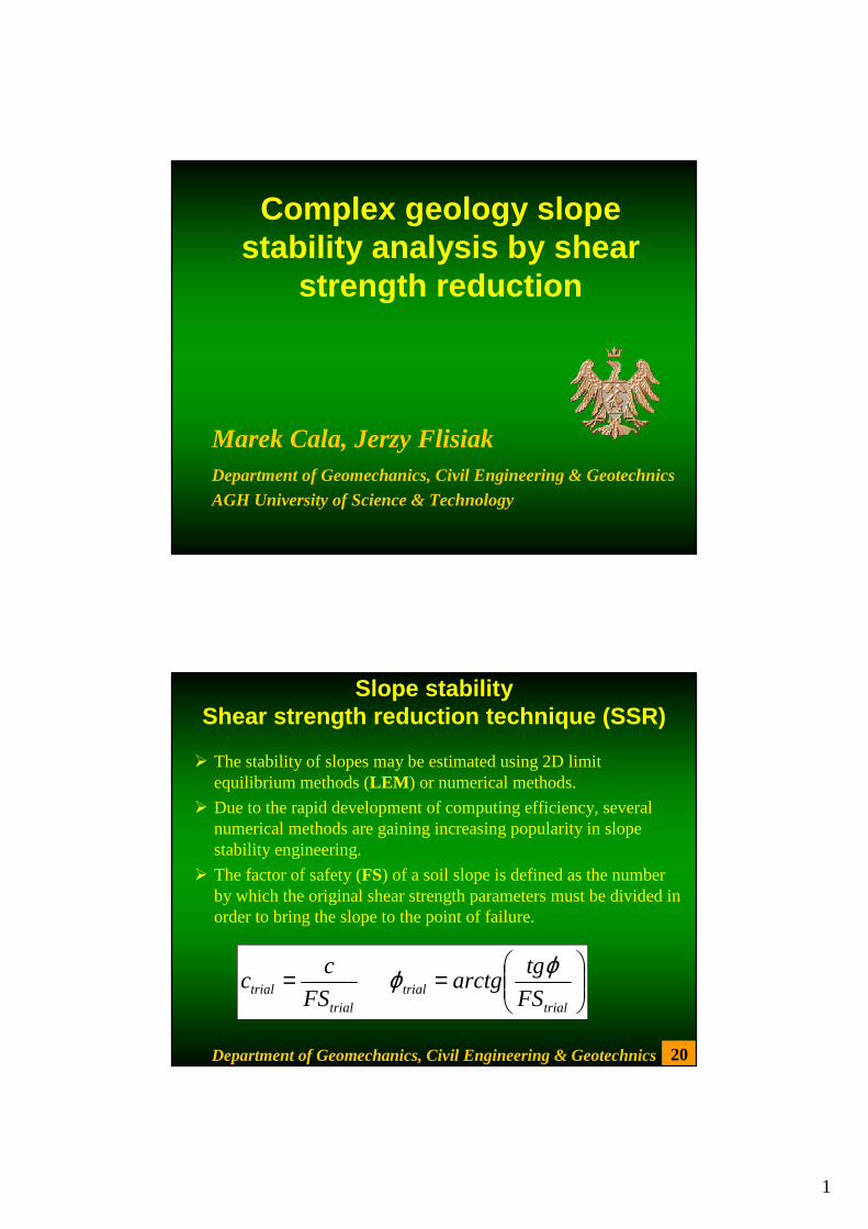
• It’s well known fact that for simple slopes FS obtained from SSR isusually the same as FS obtained from LEM (Griffiths & Lane, 1999; Cala & Flisiak, 2001).
• However, for complex geology slopes considerable differences between FS values from LEM and SSR may be expected (Cala& Flisiak, 2001).
19Department of Geomechanics, Civil Engineering & Geotechnics
Shear strength reduction technique (SSR)
25 m
25 m
hg
45o
Several analyses for the slope with weak stratumwere performed to study the differences between LEM and SSR.
Weak layer 1m thick
18Department of Geomechanics, Civil Engineering & Geotechnics
SSR versus LEM
0 10 20 30 40Distance of weak layer from slope crest
1.4
1.5
1.6
1.7
1.8
1.9
2
FS
Weak layer 1 m thickFLACFelleniusBishopJanbu
25 m
25 m
hg
45o
Hard soil c=75 kPa, φφφφ=30o
Soft soil c=25 kPa, φφφφ=10o
3
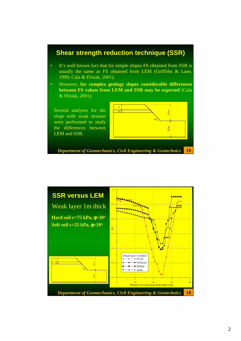
Weak layer 5m thick
17Department of Geomechanics, Civil Engineering & Geotechnics
SSR versus LEM
25 m
25 m
hg
45o
0 10 20 30 40 50Distance of weak layer from slope crest
1
1.1
1.2
1.3
1.4
1.5
1.6
1.7
1.8
1.9
2
FS
Weak layer 5 m thickFLACFelleniusBishopJanbu
Hard soil c=75 kPa, φφφφ=30o
Soft soil c=25 kPa, φφφφ=10o
16
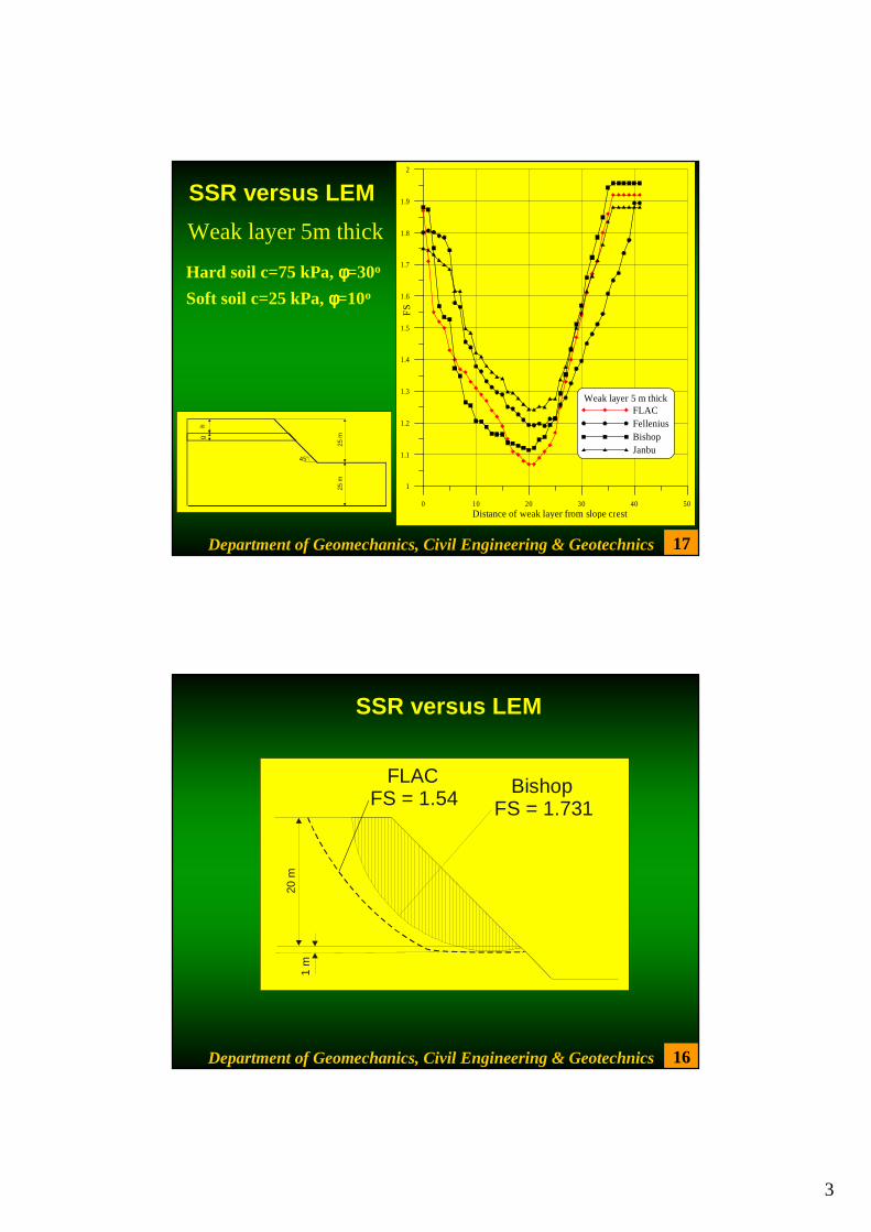
Bishop FS = 1.731
FLAC FS = 1.54
20 m
1
m
Department of Geomechanics, Civil Engineering & Geotechnics
SSR versus LEM
4
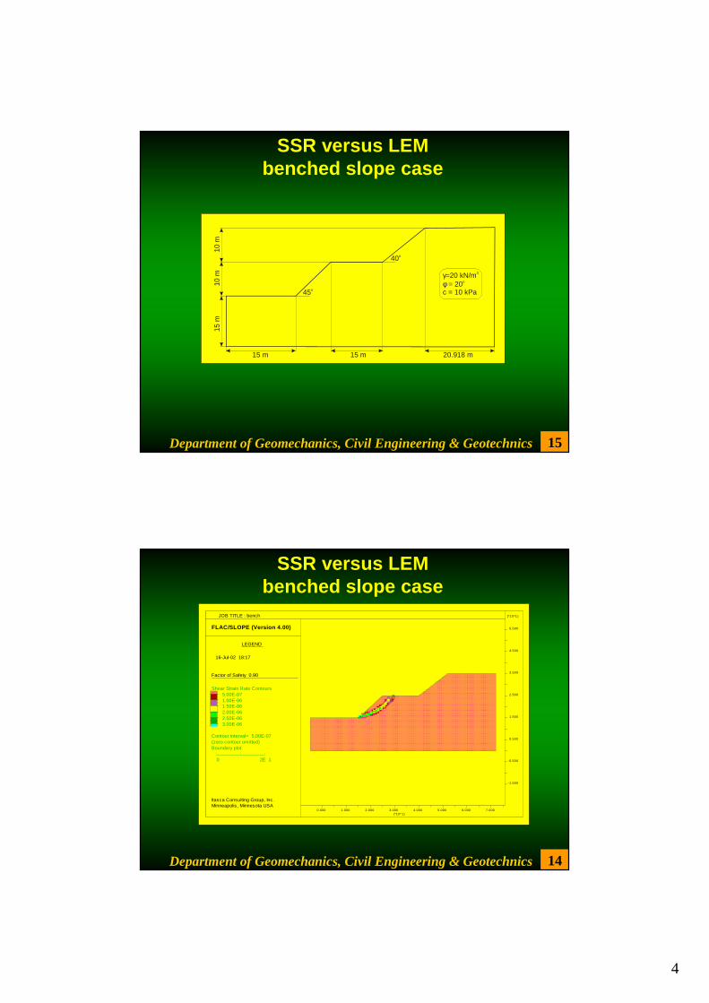
15
15 m
10
m
10 m
20.918 m15 m15 m
45o
40o
γφ=20 kN/m = 20
c = 10 kPa
3
o
Department of Geomechanics, Civil Engineering & Geotechnics
SSR versus LEMbenched slope case
14
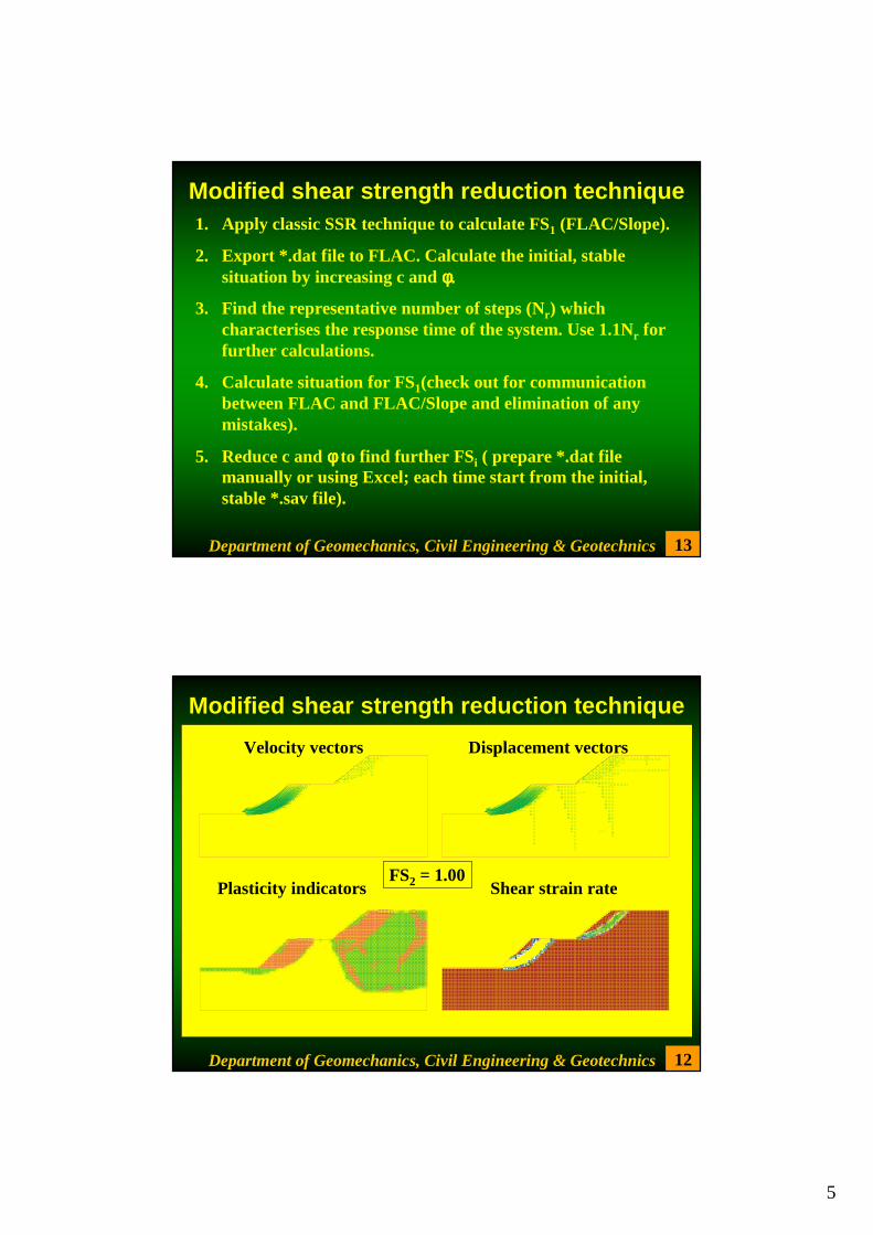
FLAC/SLOPE (Version 4.00)
LEGEND
16-Jul-02 18:17
Factor of Safety 0.90
Shear Strain Rate Contours 5.00E-07 1.00E-06 1.50E-06 2.00E-06 2.50E-06 3.00E-06
Contour interval= 5.00E-07(zero contour omitted)Boundary plot
0 2E 1
-1.500
-0.500
0.500
1.500
2.500
3.500
4.500
5.500
(*10^1)
0.000 1.000 2.000 3.000 4.000 5.000 6.000 7.000(*10^1)
JOB TITLE : bench
Itasca Consulting Group, Inc. Minneapolis, Minnesota USA
Department of Geomechanics, Civil Engineering & Geotechnics
SSR versus LEMbenched slope case
5
13 Department of Geomechanics, Civil Engineering & Geotechnics
Modified shear strength reduction technique 1. Apply classic SSR technique to calculate FS1 (FLAC/Slope).
2. Export *.dat file to FLAC. Calculate the initial, stable situation by increasing c and φ. φ. φ. φ.
3. Find the representative number of steps (Nr) which characterises the response time of the system. Use 1.1Nr for further calculations.
4. Calculate situation for FS1(check out for communication between FLAC and FLAC/Slope and elimination of any mistakes).
5. Reduce c and φ φ φ φ to find further FSi ( prepare *.dat file manually or using Excel; each time start from the initial, stable *.sav file).
12 Department of Geomechanics, Civil Engineering & Geotechnics
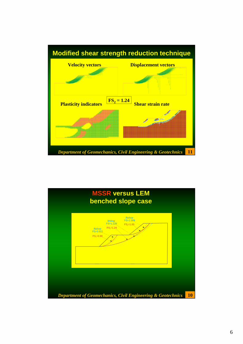
Modified shear strength reduction technique
Velocity vectors Displacement vectors
Plasticity indicators Shear strain rateFS2 = 1.00
6
11 Department of Geomechanics, Civil Engineering & Geotechnics
Modified shear strength reduction technique
Velocity vectors Displacement vectors
Plasticity indicators Shear strain rateFS2 = 1.24
10
FS =0.901
BishopFS=0.921
FS =1.002
BishopFS=1.008
FS =1.243
BishopFS=1.228
Department of Geomechanics, Civil Engineering & Geotechnics
MSSR versus LEMbenched slope case
7
9
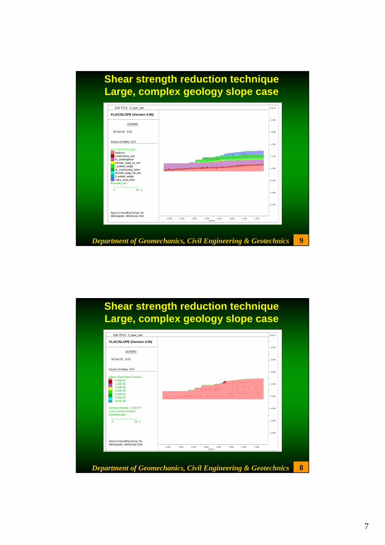
FLAC/SLOPE (Version 4.00)
LEGEND
30-Jun-02 8:24
Factor of Safety 0.67
User-defined Groupsbedrockzwietrzelina_wetily_podweglowekontakt_spag_wI_wetI_poklad_weglaily_miedzyweg_dolnekontakt_spag_wII_wetII_poklad_weglastary_zwal_wew
Boundary plot
0 2E 2
-2.500
-1.500
-0.500
0.500
1.500
2.500
3.500
4.500
(*10^2)
0.500 1.500 2.500 3.500 4.500 5.500 6.500 7.500(*10^2)
JOB TITLE : 5_layer_wet
Itasca Consulting Group, Inc. Minneapolis, Minnesota USA
Department of Geomechanics, Civil Engineering & Geotechnics
Shear strength reduction techniqueLarge, complex geology slope case
8
FLAC/SLOPE (Version 4.00)
LEGEND
30-Jun-02 8:24
Factor of Safety 0.67
Shear Strain Rate Contours 5.00E-07 1.00E-06 1.50E-06 2.00E-06 2.50E-06 3.00E-06 3.50E-06
Contour interval= 5.00E-07(zero contour omitted)Boundary plot
0 2E 2
-2.500
-1.500
-0.500
0.500
1.500
2.500
3.500
4.500
(*10^2)
0.500 1.500 2.500 3.500 4.500 5.500 6.500 7.500(*10^2)
JOB TITLE : 5_layer_wet
Itasca Consulting Group, Inc. Minneapolis, Minnesota USA
Department of Geomechanics, Civil Engineering & Geotechnics
Shear strength reduction techniqueLarge, complex geology slope case
8
7 Department of Geomechanics, Civil Engineering & Geotechnics
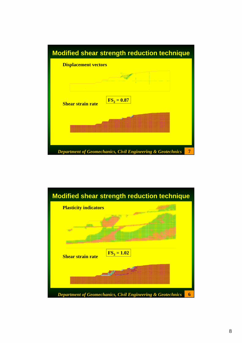
Modified shear strength reduction technique
Displacement vectors
Shear strain rateFS2 = 0.87
6 Department of Geomechanics, Civil Engineering & Geotechnics
Modified shear strength reduction technique
Plasticity indicators
Shear strain rateFS3 = 1.02
9
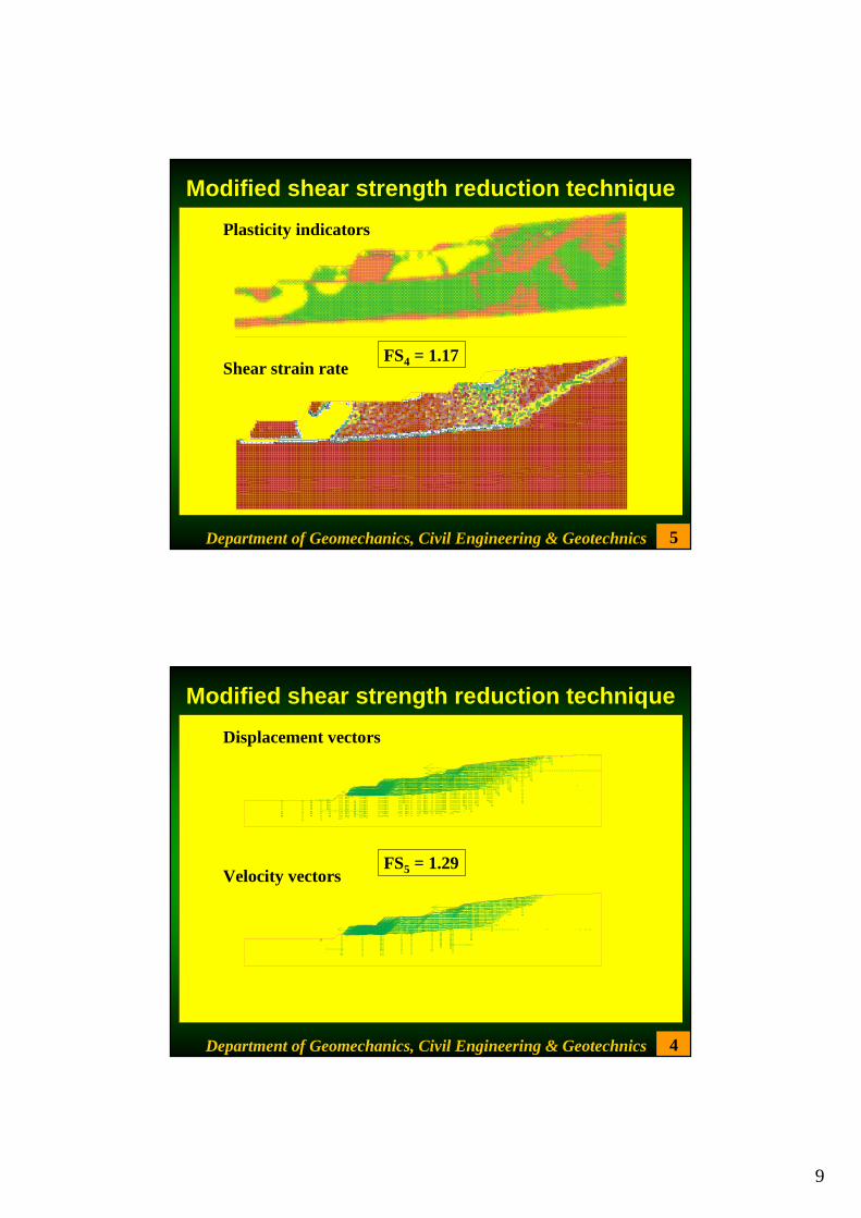
5 Department of Geomechanics, Civil Engineering & Geotechnics
Modified shear strength reduction technique
Plasticity indicators
Shear strain rateFS4 = 1.17
4 Department of Geomechanics, Civil Engineering & Geotechnics
Modified shear strength reduction technique
Displacement vectors
Velocity vectorsFS5 = 1.29
10
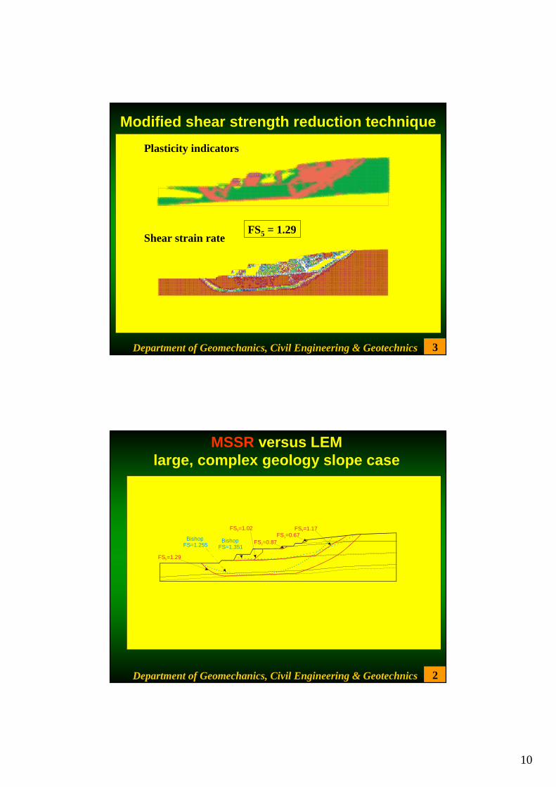
3 Department of Geomechanics, Civil Engineering & Geotechnics
Modified shear strength reduction technique
Plasticity indicators
Shear strain rateFS5 = 1.29
2
FS =0.671
FS =0.872
FS =1.023 FS =1.174
BishopFS=1.351
FS =1.295
BishopFS=1.255
Department of Geomechanics, Civil Engineering & Geotechnics
MSSR versus LEMlarge, complex geology slope case
11
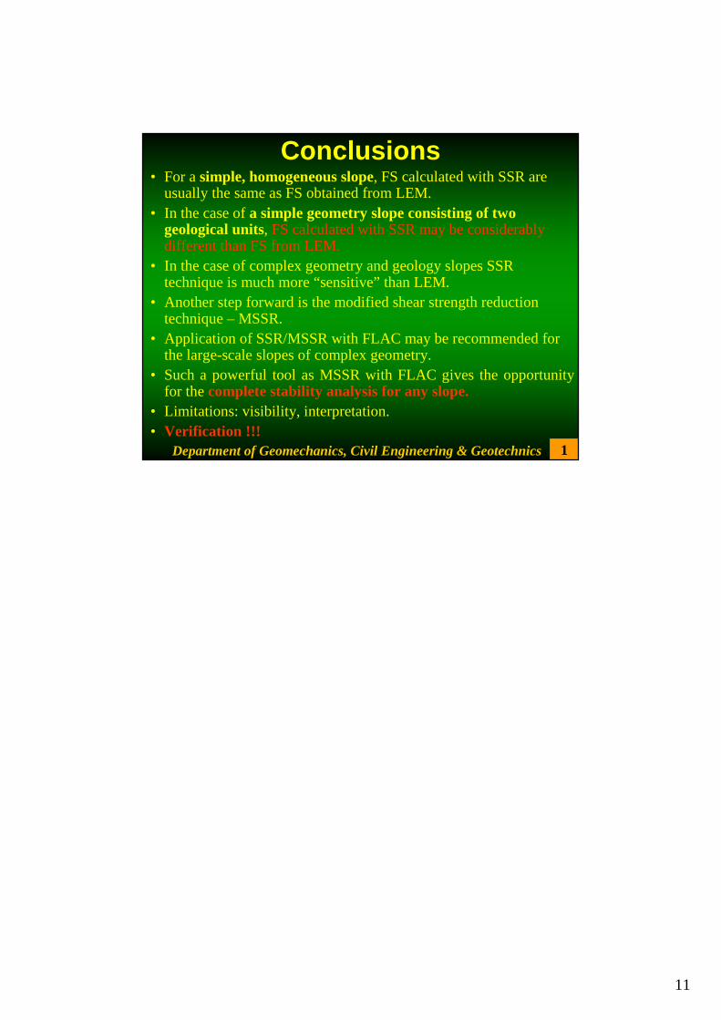
Conclusions • For a simple, homogeneous slope, FS calculated with SSR are
usually the same as FS obtained from LEM. • In the case of a simple geometry slope consisting of two
geological units, FS calculated with SSR may be considerably different than FS from LEM.
• In the case of complex geometry and geology slopes SSR technique is much more “sensitive” than LEM.
• Another step forward is the modified shear strength reduction technique – MSSR.
• Application of SSR/MSSR with FLAC may be recommended for the large-scale slopes of complex geometry.
• Such a powerful tool as MSSR with FLAC gives the opportunity for the complete stability analysis for any slope.
• Limitations: visibility, interpretation. • Verification !!!
1Department of Geomechanics, Civil Engineering & Geotechnics