COMMUNICATIONS COMPUTER Θ - 7000E Theta-7000E Manual.… · tono communications computer Θ -...
31
TONO COMMUNICATIONS COMPUTER Θ - 7000E INSTRUCTION MANUAL TONO CORPORATION 230 MOTOSOJA-MACHI, MAEBASHI-SHI, 371. JAPAN
Transcript of COMMUNICATIONS COMPUTER Θ - 7000E Theta-7000E Manual.… · tono communications computer Θ -...
TONO
COMMUNICATIONS COMPUTER
Θ - 7000E
INSTRUCTION MANUAL
TONO CORPORATION
230 MOTOSOJA-MACHI, MAEBASHI-SHI, 371. JAPAN
TABLE OF CONTENTS
1. Features & Precautions ....................................................... 12. Location and Function of controls ......................................... 4
i) Front panel (Keyboard)ii) Back panel
3. Accessories supplied ........................................................... 74. Connection ......................................................................... 7
4-1. Basic System ........................................................ 7i) Power Supplyii) TV setiii) Transceiver
4-2. Expanded System ................................................. 10i) Oscilloscopeii) Printer
5. Operationi) Preliminary Setting ......................................... 11ii) Procedure to Power Up Equipment .................. 11iii) Speed and Weight Setting ............................. 12iv) Tuning ......................................................... 13v) Transmission ................................................. 16
1. Buffer Memory2. Correction of Miswritten Characters3. Automatic Key Repeat
vi) Functions ..................................................... 171. Channel Memory2. SEND Function3. Split Screen4. Stop of Transmission5. "Stand-by" Procedure6. CW Identification7. Other Function Keys8. Indications
vii) Using a Tape Recorder for Storage ................ 226. Application of a Microcomputer as an Intelligent Terminal ...... 237. How to Set Cells for the Battery Backed-up Memory .............. 23
Key function and display ......................................................... 24Special Character ASCII 00–1F ................................................ 27Specifications ......................................................................... 28Input/ Output Circuit .............................................................. 29
- 1 -
1. FEATURES & PRECAUTIONS
Features:
1. Communications Computer Θ-7000EDue to the most up-to-date computer technology, one piece of equipment can now handleboth transmitting and receiving in CW, RTTY and ASCII.
2. VHF and Composite video output provided:Both a home TV set and video monitor outputs are provided for display purposes.
3. Printer interfaceCentronics para. Compatible interface enables easy connection of a low-cost dot printer forhard copies.
4. Wide range of transmitting and receiving speeds10 communication speeds for transmitting (with automatic CW speed adjustment of re-ceive) and 9 communication speeds for transmitting and receiving in RTTY and ASCII. Themultiple speed feature makes the Θ-7000E ideal for Amateur, business and commercial use.
5. Built-in demodulator for high performanceThree-step shift (either 170 Hz, 425 Hz, 850 Hz) can be obtained using either High Tone orLow Tones. Manual adjustment is available by FINE TUNING control.
6. Crystal controlled modulatorA transceiver without FSK function can transmit in RTTY mode by utilizing the high stabilitycrystal-controlled modulator controlled by the computer.
7. Convenient ASCII key arrangementThe keyboard layout is the same as a regular typewriter and automatic insertion of LTR/FIGcode makes operation a breeze.
8. Large capacity display memoryThe two-page display memory contains 32 characters × 16 lines per page. Page selectionis operated via the keyboard.
9. Split-screenWith a keyboard command, the first page can be divided in two; the upper half for transmitand the lower half for receive. Sentences can be edited whilst receiving.
10. Automatic Transmit/Receive switchThe transmit/receive switch is controlled by the microprocessor. (Manual operation is alsoavailable.) Built-in remote control key function controls the transmit/receive switch of thetransceiver.
11. Anti-noiseA new anti-noise circuit prevents garbled messages when there is no signal.
12. Battery backed-up memoryData in the battery backed-up memory is retained when the external power source is re-moved. The Θ-7000E has provision for 64 characters × 7 channels in the non-volatilememory. Data from a memory can be repeated 1–9 times from a keyboard instruction.Every channel can read out continuously. The channel number in use is displayed in thebuffer.
13. SEND functionThe SEND function sends data displayed on the screen, including any channel data after in-struction from the keyboard. The message can be stopped and restarted.
14. Buffer memoryA 53-character-buffer-memory is displayed on the 17th and 18th lines on the screen. Thecharacters move to the left erasing one by one as soon as they are transmitted. Data in thechannels can be displayed in the buffer.
15. Rub out functionMistakes can be erased whilst the information is still in the buffer memory. If the mistakehas already been sent a correcting code will be transmitted.
16. Simultaneous access of the memoryWhilst receiving, it is possible to write into the channel memory and the buffer memoryfrom the keyboard. When sending from the channel memory or the screen it is possible to
- 2 -
write into the buffer memory.17. Pre-loading function
The buffer memory can momentarily store data and release it on an instruction from thekeyboard.
18. Channel No., Page No., and Case No.Channel No., Page No., and Case (LTR/FIG) in RTTY are displayed in the 17th line of thescreen.
19. CR (Carriage return)/LF (line feed) cancel functionWhen receiving CR or LF, they are replaced by = (equal) and _ (underline) respectively foreffective use of the screen.
20. Cursor control functionFull cursor control (up/down-left/right) is available from the keyboard.
21. WORD MODE operationCharacters can be transmitted by word groupings.
22. Automatic CR/LFWhile sending, CR/LF are automatically inserted once every 72 (64 or 80) characters.
23. Automatic LETTER code insertionWith LETTER switch ON, LETTER code can be transmitted continuously while transmittingfrom the keyboard is stopped.
24. ECHO-BACK functionWith a keyboard instruction, received data can be read and sent out at the time. A cassettetape can be used as the source data.
25. WORD-WRAP-AROUND functionIn receive mode word-wrap-around prevents the last word of the line from splitting in two.This function is released with a keyboard instruction.
26. Transmit/receive in ASCII mode in RTTYOn instruction from the keyboard, the same AFSK signals as used in RTTY are transmittedin ASCII mode.
27. CW Identification functionKeyboard controlled CW identification is available if required.
28. MARK-AND-BREAK (SPACE-AND-BREAK) systemEither mark or space tone can be used to copy RTTY.
29. Monitor circuitA built-in-monitor circuit with an automatic transmit/receive switch enables checking of thetransmitting and receiving state. In receive mode it is possible to check the output of themark filter, the space filter and AGC amplifier prior to the filters.
30. CW practice functionThe Θ-7000E reads data from the key and displays the characters on the screen.
31. Variable CW weightsFor CW transmission, weights (ratio of dot to dash) can be changed within the limits of1:3–1:6.
32. Cross-pattern checking output terminalProvision has been made for attachment of an oscilloscope to aid tuning. This supplementsthe tuning LED and audio monitor provided in the system.
33. Log-computer output providedThe Θ-7000E has an output terminal for connection to a log-keeping computer.
34. Test message function"RY" and "QBF" test messages can be repeated with this function.
- 3 -
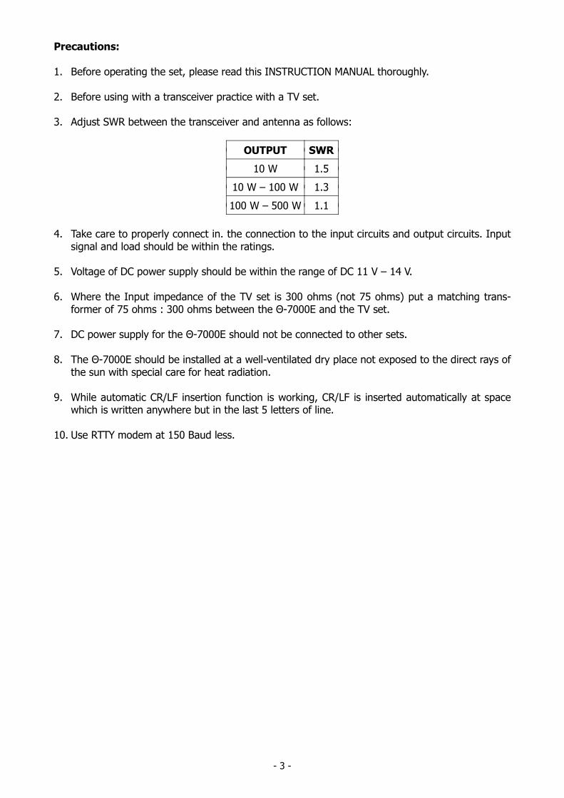
Precautions:
1. Before operating the set, please read this INSTRUCTION MANUAL thoroughly.
2. Before using with a transceiver practice with a TV set.
3. Adjust SWR between the transceiver and antenna as follows:
OUTPUT SWR
10 W 1.5
10 W – 100 W 1.3
100 W – 500 W 1.1
4. Take care to properly connect in. the connection to the input circuits and output circuits. Inputsignal and load should be within the ratings.
5. Voltage of DC power supply should be within the range of DC 11 V – 14 V.
6. Where the Input impedance of the TV set is 300 ohms (not 75 ohms) put a matching trans-former of 75 ohms : 300 ohms between the Θ-7000E and the TV set.
7. DC power supply for the Θ-7000E should not be connected to other sets.
8. The Θ-7000E should be installed at a well-ventilated dry place not exposed to the direct rays ofthe sun with special care for heat radiation.
9. While automatic CR/LF insertion function is working, CR/LF is inserted automatically at spacewhich is written anywhere but in the last 5 letters of line.
10. Use RTTY modem at 150 Baud less.
- 4 -
2. LOCATION AND FUNCTION OF CONTROLS
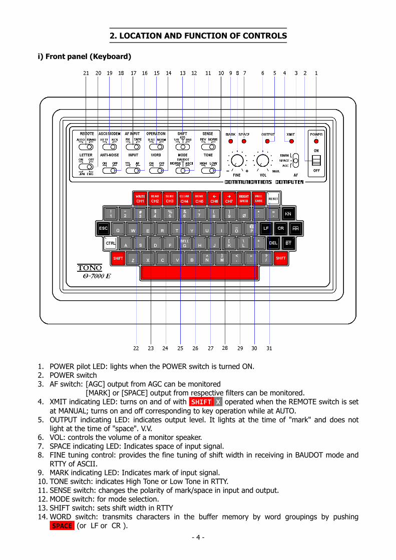
i) Front panel (Keyboard)
1. POWER pilot LED: lights when the POWER switch is turned ON.2. POWER switch3. AF switch: [AGC] output from AGC can be monitored
[MARK] or [SPACE] output from respective filters can be monitored.4. XMIT indicating LED: turns on and of with SHIFT X operated when the REMOTE switch is set
at MANUAL; turns on and off corresponding to key operation while at AUTO.5. OUTPUT indicating LED: indicates output level. It lights at the time of "mark" and does not
light at the time of "space". V.V.6. VOL: controls the volume of a monitor speaker.7. SPACE indicating LED: Indicates space of input signal.8. FINE tuning control: provides the fine tuning of shift width in receiving in BAUDOT mode and
RTTY of ASCII.9. MARK indicating LED: Indicates mark of input signal.10. TONE switch: indicates High Tone or Low Tone in RTTY.11. SENSE switch: changes the polarity of mark/space in input and output.12. MODE switch: for mode selection.13. SHIFT switch: sets shift width in RTTY14. WORD switch: transmits characters in the buffer memory by word groupings by pushing
SPACE (or LF or CR ).
- 5 -
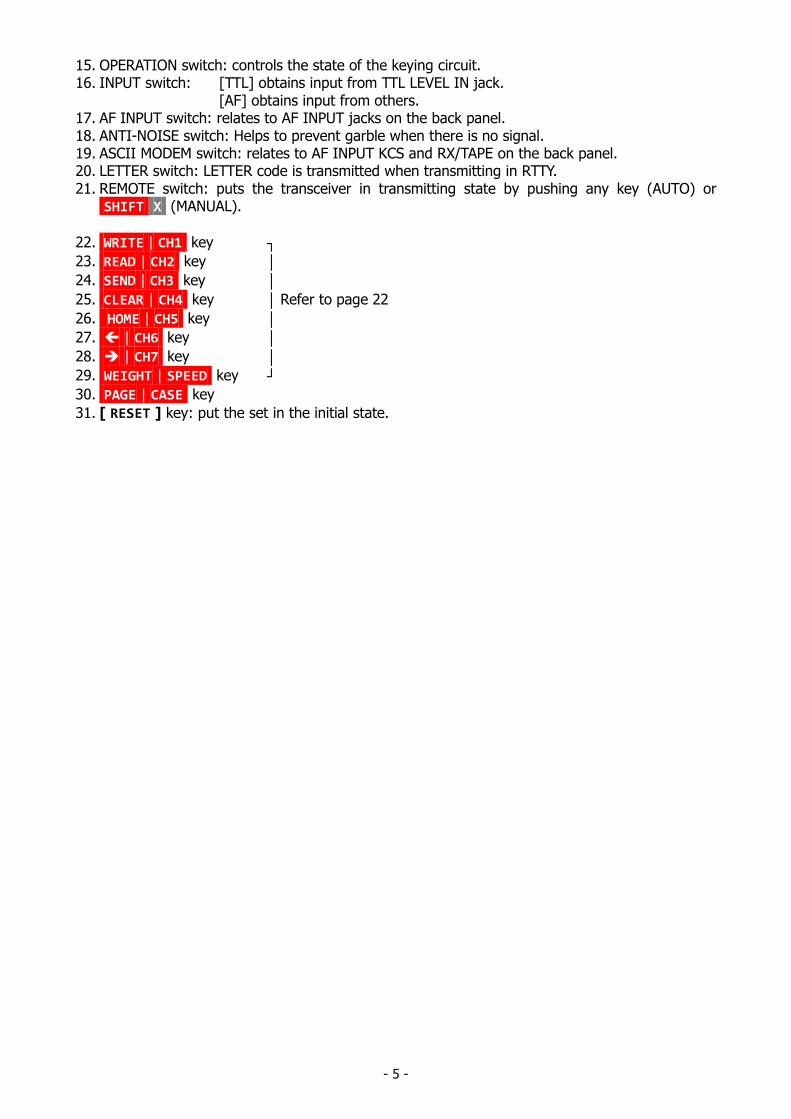
15. OPERATION switch: controls the state of the keying circuit.16. INPUT switch: [TTL] obtains input from TTL LEVEL IN jack.
[AF] obtains input from others.17. AF INPUT switch: relates to AF INPUT jacks on the back panel.18. ANTI-NOISE switch: Helps to prevent garble when there is no signal.19. ASCII MODEM switch: relates to AF INPUT KCS and RX/TAPE on the back panel.20. LETTER switch: LETTER code is transmitted when transmitting in RTTY.21. REMOTE switch: puts the transceiver in transmitting state by pushing any key (AUTO) or
SHIFT X (MANUAL).
22. WRITE | CH1 key 23. READ | CH2 key 24. SEND | CH3 key 25. CLEAR | CH4 key Refer to page 22
26. HOME | CH5 key 27. | CH6 key 28. | CH7 key 29. WEIGHT | SPEED key 30. PAGE | CASE key
31. [ RESET ] key: put the set in the initial state.
- 6 -
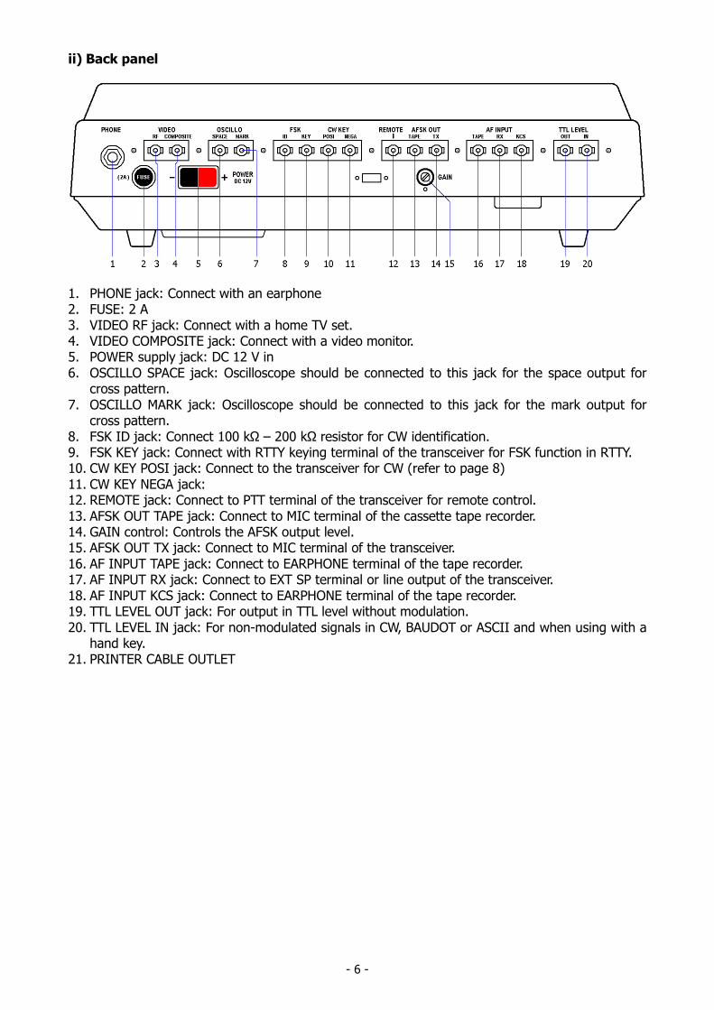
ii) Back panel
1. PHONE jack: Connect with an earphone2. FUSE: 2 A3. VIDEO RF jack: Connect with a home TV set.4. VIDEO COMPOSITE jack: Connect with a video monitor.5. POWER supply jack: DC 12 V in6. OSCILLO SPACE jack: Oscilloscope should be connected to this jack for the space output for
cross pattern.7. OSCILLO MARK jack: Oscilloscope should be connected to this jack for the mark output for
cross pattern.8. FSK ID jack: Connect 100 kΩ – 200 kΩ resistor for CW identification.9. FSK KEY jack: Connect with RTTY keying terminal of the transceiver for FSK function in RTTY.10. CW KEY POSI jack: Connect to the transceiver for CW (refer to page 8)11. CW KEY NEGA jack:12. REMOTE jack: Connect to PTT terminal of the transceiver for remote control.13. AFSK OUT TAPE jack: Connect to MIC terminal of the cassette tape recorder.14. GAIN control: Controls the AFSK output level.15. AFSK OUT TX jack: Connect to MIC terminal of the transceiver.16. AF INPUT TAPE jack: Connect to EARPHONE terminal of the tape recorder.17. AF INPUT RX jack: Connect to EXT SP terminal or line output of the transceiver.18. AF INPUT KCS jack: Connect to EARPHONE terminal of the tape recorder.19. TTL LEVEL OUT jack: For output in TTL level without modulation.20. TTL LEVEL IN jack: For non-modulated signals in CW, BAUDOT or ASCII and when using with a
hand key.21. PRINTER CABLE OUTLET
- 7 -
3. ACCESSORIES SUPPLIED
Instruction manual 1Pin plug 16Headphone plug 1Power source cord 1Coaxial cable 4 mConnector for printer 1
4. CONNECTION
4-1 Basic System
i) Power supplyBefore connecting a power lead to your DC power supply, the setting of the voltage mustbe within the range of DC 11 V – 14 V.After confirming that the DC source switch and POWER switch of the Θ-7000E indicatesOFF, connect a plus (+) of POWER supply jack of the Θ-7000E with the plus (+) terminal ofDC source; minus (–) with minus (–) terminal.
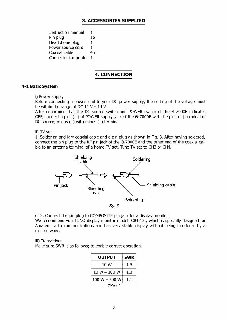
ii) TV set1. Solder an ancillary coaxial cable and a pin plug as shown in Fig. 3. After having soldered,connect the pin plug to the RF pin jack of the Θ-7000E and the other end of the coaxial ca-ble to an antenna terminal of a home TV set. Tune TV set to CH3 or CH4,
Fig. 3
or 2. Connect the pin plug to COMPOSITE pin jack for a display monitor.We recommend you TONO display monitor model: CRT-12,, which is specially designed forAmateur radio communications and has very stable display without being interfered by aelectric wave.
iii) TransceiverMake sure SWR is as follows; to enable correct operation.
OUTPUT SWR
10 W 1.5
10 W – 100 W 1.3
100 W – 500 W 1.1
Table 1
- 8 -
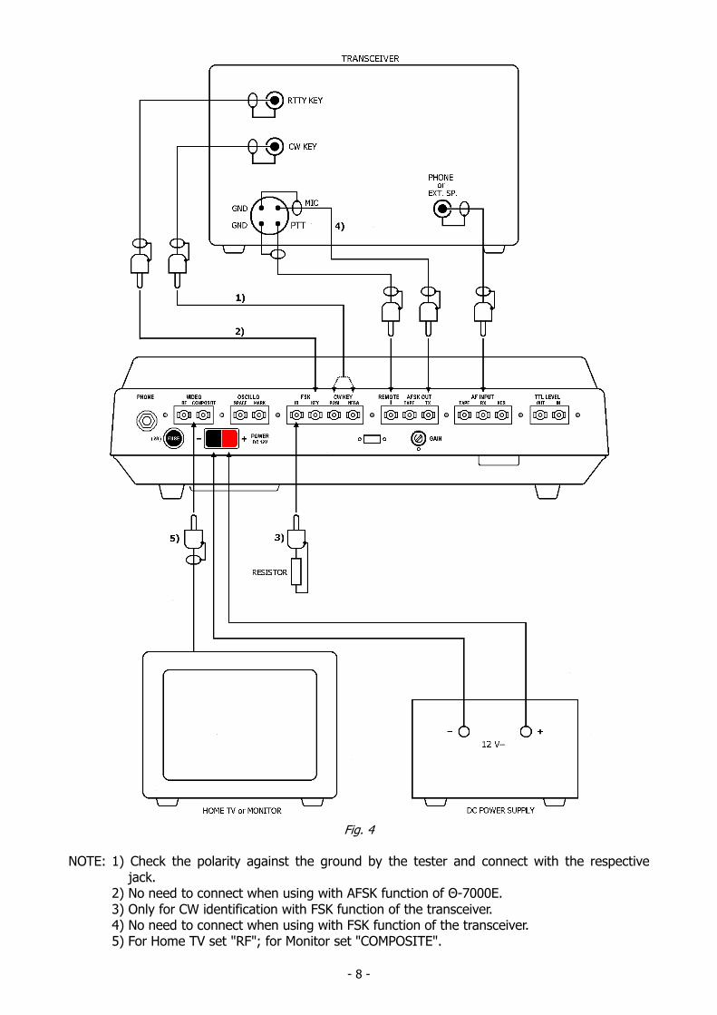
Fig. 4
NOTE: 1) Check the polarity against the ground by the tester and connect with the respective jack.2) No need to connect when using with AFSK function of Θ-7000E.3) Only for CW identification with FSK function of the transceiver.4) No need to connect when using with FSK function of the transceiver.5) For Home TV set "RF"; for Monitor set "COMPOSITE".
- 9 -
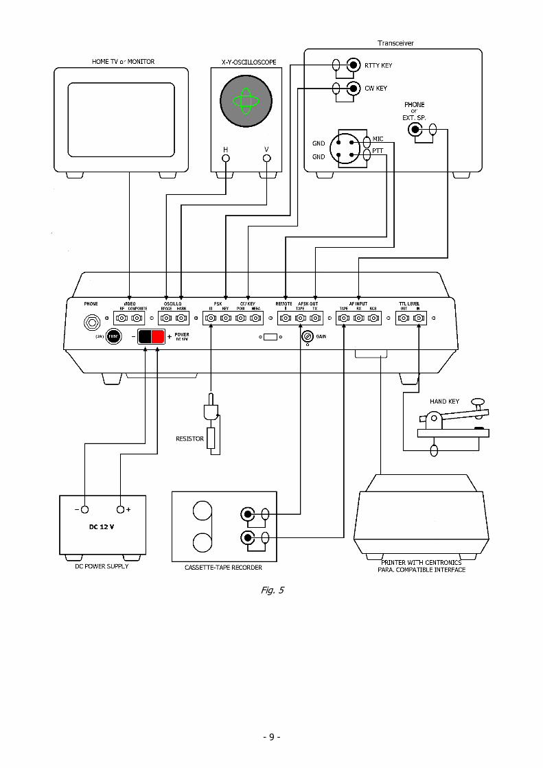
Fig. 5
- 10 -
4-2 Expanded System
Refer to page 9 for detail.
i) OscilloscopeAs output impedance for oscilloscope is 200 kΩ, use an oscilloscope whose input im-pedance is over 1 MΩ. As output for oscilloscope is about 1.2 VPP, large cross pat-
tern cannot be obtained without an amplifier in horizontal-amplifier of the oscillo-scope.
ii) PrinterA printer which has Centronics compatible interface can be connected directly withthe Θ-7000E.We recommend the TONO printer model HC-800, which is easy to connect becauseof its supplied cable with connector for the Θ-7000E.
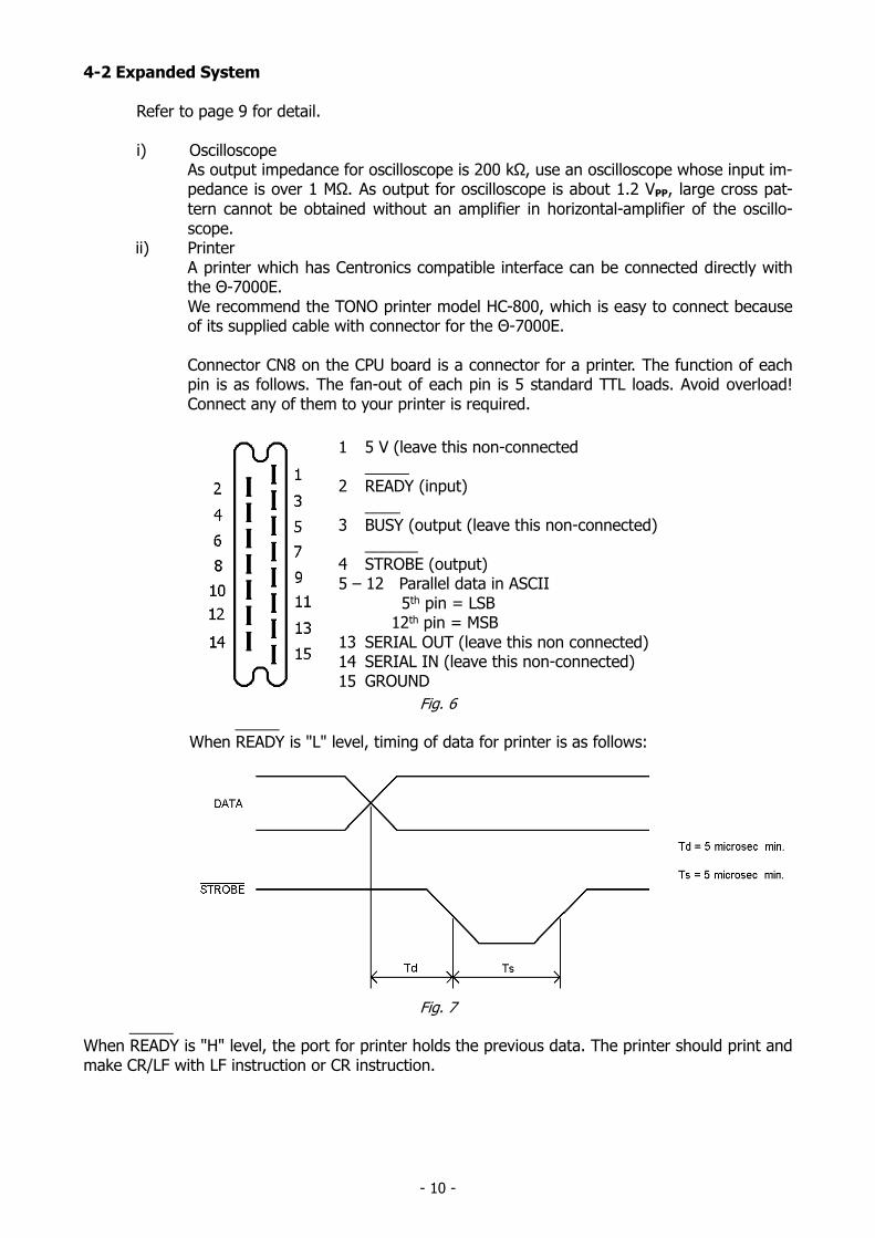
Connector CN8 on the CPU board is a connector for a printer. The function of eachpin is as follows. The fan-out of each pin is 5 standard TTL loads. Avoid overload!Connect any of them to your printer is required.
1 5 V (leave this non-connected_____
2 READY (input)____
3 BUSY (output (leave this non-connected)______
4 STROBE (output)5 – 12 Parallel data in ASCII
5th pin = LSB12th pin = MSB
13 SERIAL OUT (leave this non connected)14 SERIAL IN (leave this non-connected)15 GROUND
Fig. 6
_____When READY is "L" level, timing of data for printer is as follows:
Fig. 7
_____When READY is "H" level, the port for printer holds the previous data. The printer should print andmake CR/LF with LF instruction or CR instruction.
- 11 -
5. OPERATION
i) Preliminary Setting
Theta-7000E
FrontPanel
POWER swVOL tuning controlMODE swOPERATION swSENSE swREMOTE swASCII MODEM swAF INPUT swLETTER swANTI-NOISE swINPUT swWORD swAF swFINE tuning controlTONE swSHIFT sw
OFFmedium---NORMNORM---KSCRX------AF---AGCmedium---(any place)when in BAUDOTmode select theproper shift
BackPanel
AFSK GAIN control around medium
--- : as required
DC power supply
POWER sw OFF
TV set
POWER swVHF channel(Home TV)
OFFCH 4 (Australia &
Continental)CH 3 (USA)
Transceiver
MODE sw
according to the MODE swsetting of the Θ-7000E.w/o FSK functionLSB setting is required forRTTY.
POWER sw OFF
AF volume
Set it so as to make the inputvoltage into the Θ-7000Eranging from 50 mV to 1 V(ordinary listening volume)
Table 2
ii) Procedure to power up equipment
Put the power switch ON of: 1. TV set2. DC power supply3. The Θ-7000E4. Transceiver
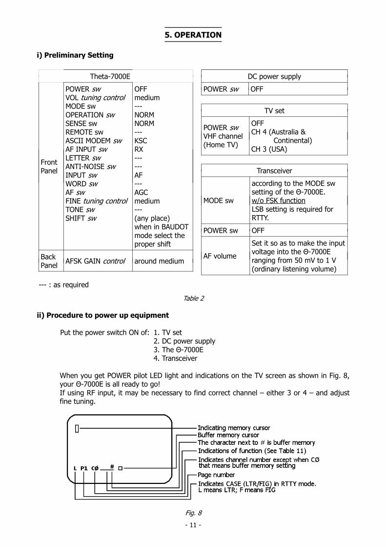
When you get POWER pilot LED light and indications on the TV screen as shown in Fig. 8,your Θ-7000E is all ready to go!If using RF input, it may be necessary to find correct channel – either 3 or 4 – and adjustfine tuning.
Fig. 8
- 12 -
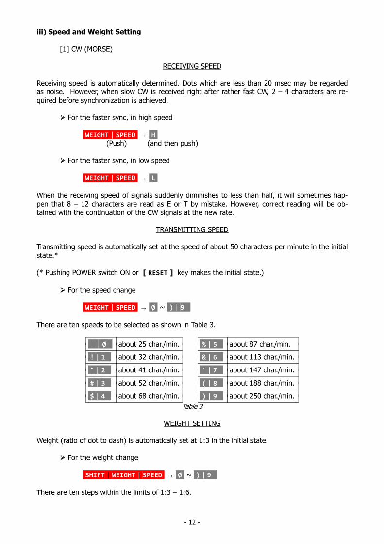
iii) Speed and Weight Setting
[1] CW (MORSE)
RECEIVING SPEED
Receiving speed is automatically determined. Dots which are less than 20 msec may be regardedas noise. However, when slow CW is received right after rather fast CW, 2 – 4 characters are re-quired before synchronization is achieved.
For the faster sync, in high speed
WEIGHT | SPEED → H
(Push) (and then push)
For the faster sync, in low speed
WEIGHT | SPEED → L
When the receiving speed of signals suddenly diminishes to less than half, it will sometimes hap-pen that 8 – 12 characters are read as E or T by mistake. However, correct reading will be ob-tained with the continuation of the CW signals at the new rate.
TRANSMITTING SPEED
Transmitting speed is automatically set at the speed of about 50 characters per minute in the initialstate.*
(* Pushing POWER switch ON or [ RESET ] key makes the initial state.)
For the speed change
WEIGHT | SPEED → Ø ~ ) | 9
There are ten speeds to be selected as shown in Table 3.
Ø about 25 char./min. % | 5 about 87 char./min.
! | 1 about 32 char./min. & | 6 about 113 char./min.
" | 2 about 41 char./min. ' | 7 about 147 char./min.
# | 3 about 52 char./min. ( | 8 about 188 char./min.
$ | 4 about 68 char./min. ) | 9 about 250 char./min.
Table 3
WEIGHT SETTING
Weight (ratio of dot to dash) is automatically set at 1:3 in the initial state.
For the weight change
SHIFT | WEIGHT | SPEED → Ø ~ ) | 9
There are ten steps within the limits of 1:3 – 1:6.
- 13 -
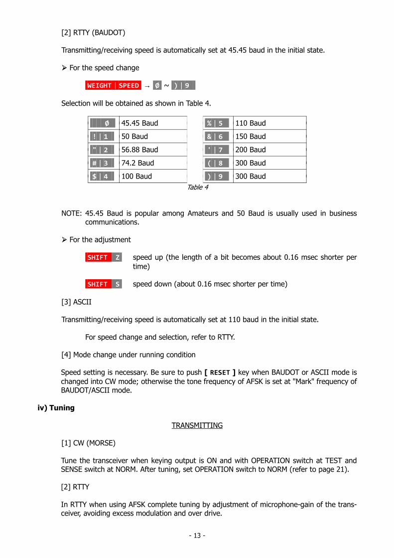
[2] RTTY (BAUDOT)
Transmitting/receiving speed is automatically set at 45.45 baud in the initial state.
For the speed change
WEIGHT | SPEED → Ø ~ ) | 9
Selection will be obtained as shown in Table 4.
Ø 45.45 Baud % | 5 110 Baud
! | 1 50 Baud & | 6 150 Baud
" | 2 56.88 Baud ' | 7 200 Baud
# | 3 74.2 Baud ( | 8 300 Baud
$ | 4 100 Baud ) | 9 300 Baud
Table 4
NOTE: 45.45 Baud is popular among Amateurs and 50 Baud is usually used in businesscommunications.
For the adjustment
SHIFT Z speed up (the length of a bit becomes about 0.16 msec shorter per
time)
SHIFT S speed down (about 0.16 msec shorter per time)
[3] ASCII
Transmitting/receiving speed is automatically set at 110 baud in the initial state.
For speed change and selection, refer to RTTY.
[4] Mode change under running condition
Speed setting is necessary. Be sure to push [ RESET ] key when BAUDOT or ASCII mode is
changed into CW mode; otherwise the tone frequency of AFSK is set at "Mark" frequency ofBAUDOT/ASCII mode.
iv) Tuning
TRANSMITTING
[1] CW (MORSE)
Tune the transceiver when keying output is ON and with OPERATION switch at TEST andSENSE switch at NORM. After tuning, set OPERATION switch to NORM (refer to page 21).
[2] RTTY
In RTTY when using AFSK complete tuning by adjustment of microphone-gain of the trans-ceiver, avoiding excess modulation and over drive.
- 14 -
RECEIVING
[1] CW (MORSE)
Using LED indicator
1. Receive CW with the transceiver.2. SPACE indicating LED lights when the CW signals from the transceiver pass through the
band-pass-filter of which the central frequency is 830 Hz.3. Tune VFO or RIT of the transceiver so as to make this SPACE indicating LED have maxi-
mum brightness.
Using audio level
1. Set AF switch to SPACE.2. Output of the band-pass-filter can be heard.3. Adjust the transceiver to have the maximum sound level.
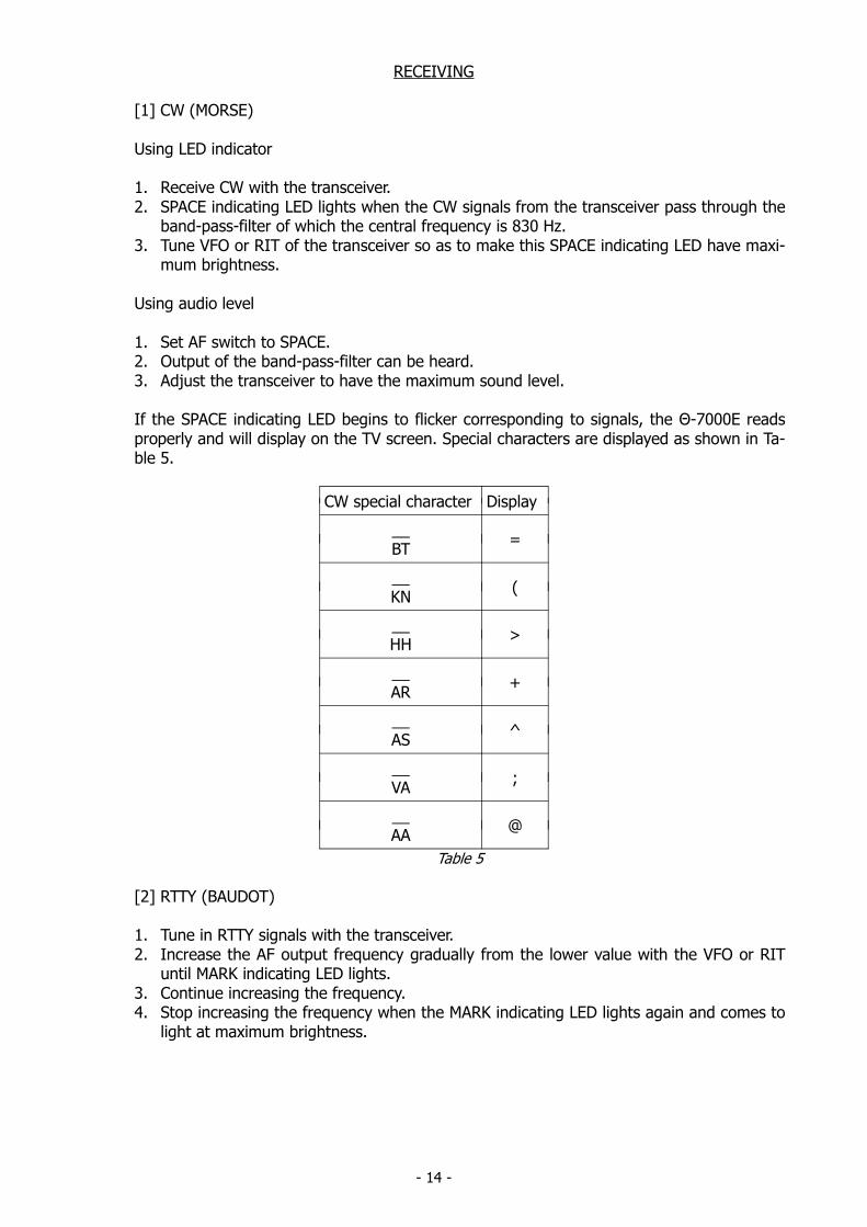
If the SPACE indicating LED begins to flicker corresponding to signals, the Θ-7000E readsproperly and will display on the TV screen. Special characters are displayed as shown in Ta-ble 5.
CW special character Display
__BT
=
__KN
(
__HH
>
__AR
+
__AS
^
__VA
;
__AA
@
Table 5
[2] RTTY (BAUDOT)
1. Tune in RTTY signals with the transceiver.2. Increase the AF output frequency gradually from the lower value with the VFO or RIT
until MARK indicating LED lights.3. Continue increasing the frequency.4. Stop increasing the frequency when the MARK indicating LED lights again and comes to
light at maximum brightness.
- 15 -
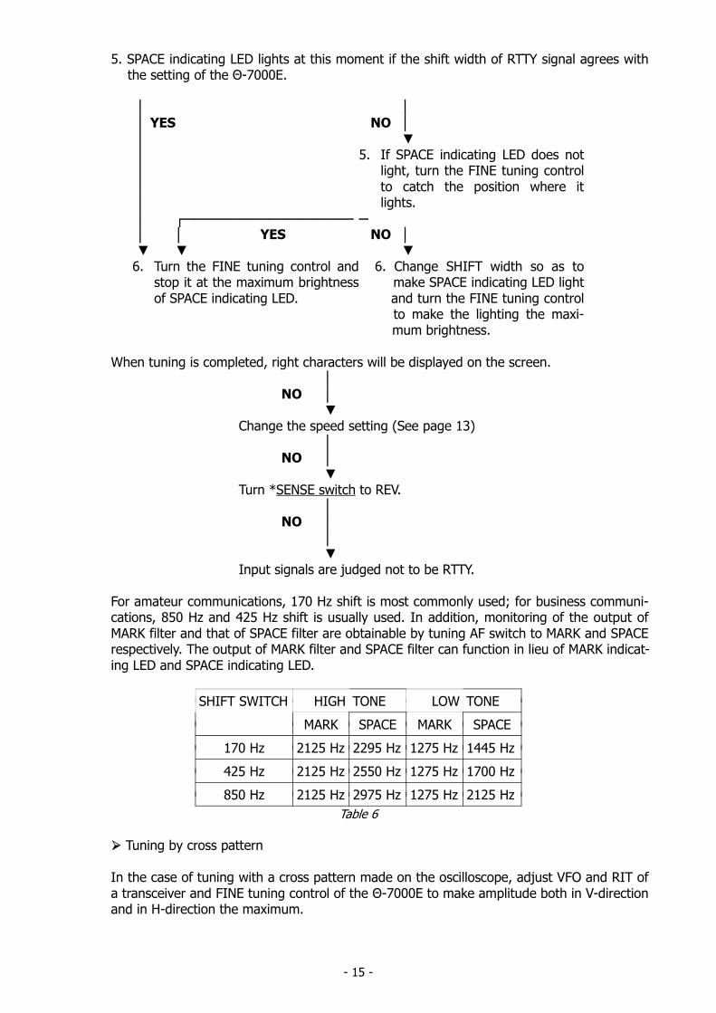
5. SPACE indicating LED lights at this moment if the shift width of RTTY signal agrees with the setting of the Θ-7000E.
YES YES
NO
5. If SPACE indicating LED does not
light, turn the FINE tuning controlto catch the position where itlights.
NO
6. Turn the FINE tuning control and
stop it at the maximum brightnessof SPACE indicating LED.
6. Change SHIFT width so as to make SPACE indicating LED light and turn the FINE tuning control to make the lighting the maxi- mum brightness.
When tuning is completed, right characters will be displayed on the screen.
NO
Change the speed setting (See page 13)
NO
Turn *SENSE switch to REV.
NO
Input signals are judged not to be RTTY.
For amateur communications, 170 Hz shift is most commonly used; for business communi-cations, 850 Hz and 425 Hz shift is usually used. In addition, monitoring of the output ofMARK filter and that of SPACE filter are obtainable by tuning AF switch to MARK and SPACErespectively. The output of MARK filter and SPACE filter can function in lieu of MARK indicat-ing LED and SPACE indicating LED.
SHIFT SWITCH HIGH TONE LOW TONE
MARK SPACE MARK SPACE
170 Hz 2125 Hz 2295 Hz 1275 Hz 1445 Hz
425 Hz 2125 Hz 2550 Hz 1275 Hz 1700 Hz
850 Hz 2125 Hz 2975 Hz 1275 Hz 2125 Hz
Table 6
Tuning by cross pattern
In the case of tuning with a cross pattern made on the oscilloscope, adjust VFO and RIT ofa transceiver and FINE tuning control of the Θ-7000E to make amplitude both in V-directionand in H-direction the maximum.
- 16 -
[3] ASCII
When using KCS
Tuning by watching the LEDs or by listening the transmitting sound from the speaker is notavailable in this mode.
Receive signals of 2400 Hz for mark and 1200 Hz for space in accordance with KCS (KansasCity Standard) from a tape recorder or a microcomputer.
When using RTTY (ASCII)
Tuning is the same as in BAUDOT mode.
[4] NOISE
ANTI-NOISE circuit
When there are too many errors caused by noise when there is no signal, set the ANTI-NOISE switch ON. This circuit may make mistakes with high speed CW (Morse) of which adot is shorter than 20 msec.
UNSHIFT-ON-SPACE function (only in BAUDOT)
When error in CASE (LTR or FIG) is often made with a lot of noise, push SHIFT Y UN-
SHIFT-ON-SPACE function works and leads the LTR case when space is received.
# is replaced by * on the 17th line. To release this function push these keys again.
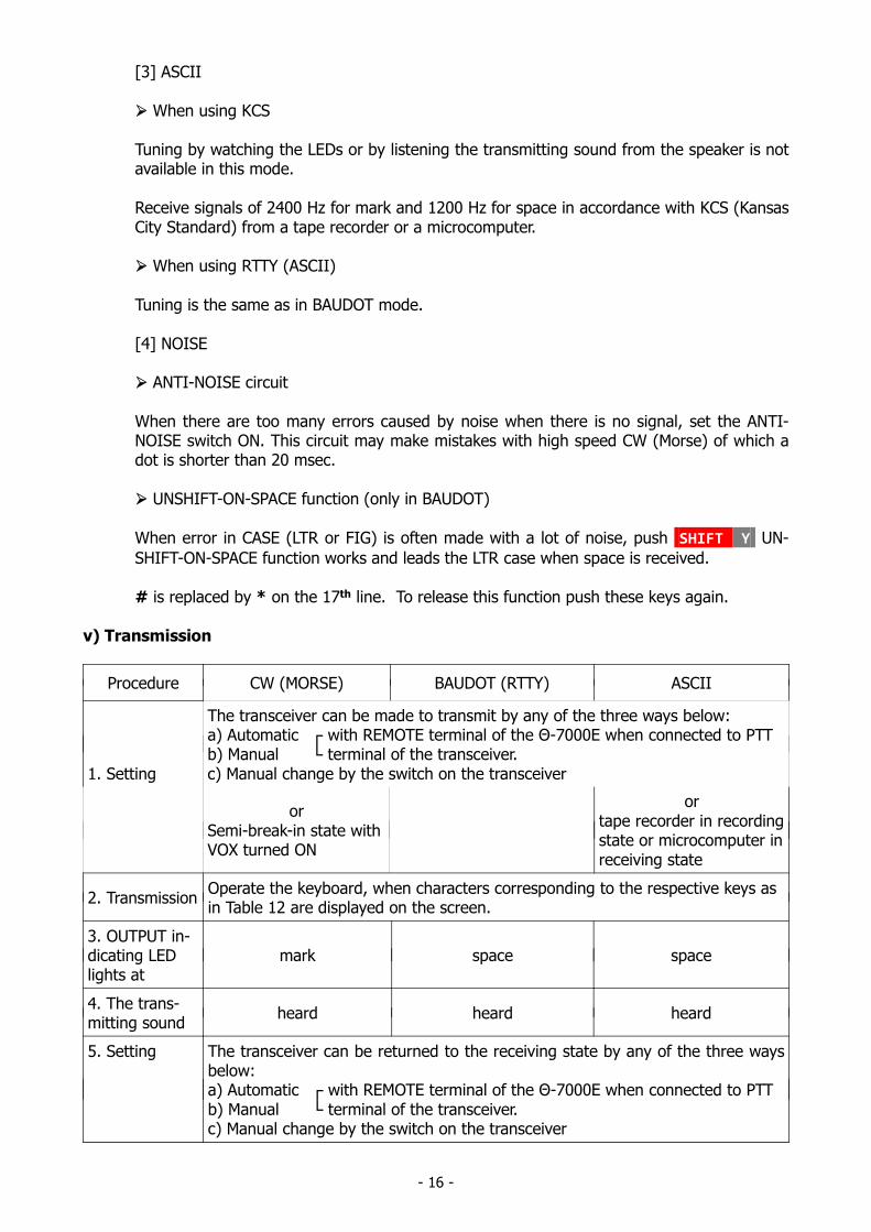
v) Transmission
Procedure CW (MORSE) BAUDOT (RTTY) ASCII
1. Setting
The transceiver can be made to transmit by any of the three ways below:a) Automatic with REMOTE terminal of the Θ-7000E when connected to PTTb) Manual terminal of the transceiver.c) Manual change by the switch on the transceiver
orSemi-break-in state withVOX turned ON
ortape recorder in recordingstate or microcomputer inreceiving state
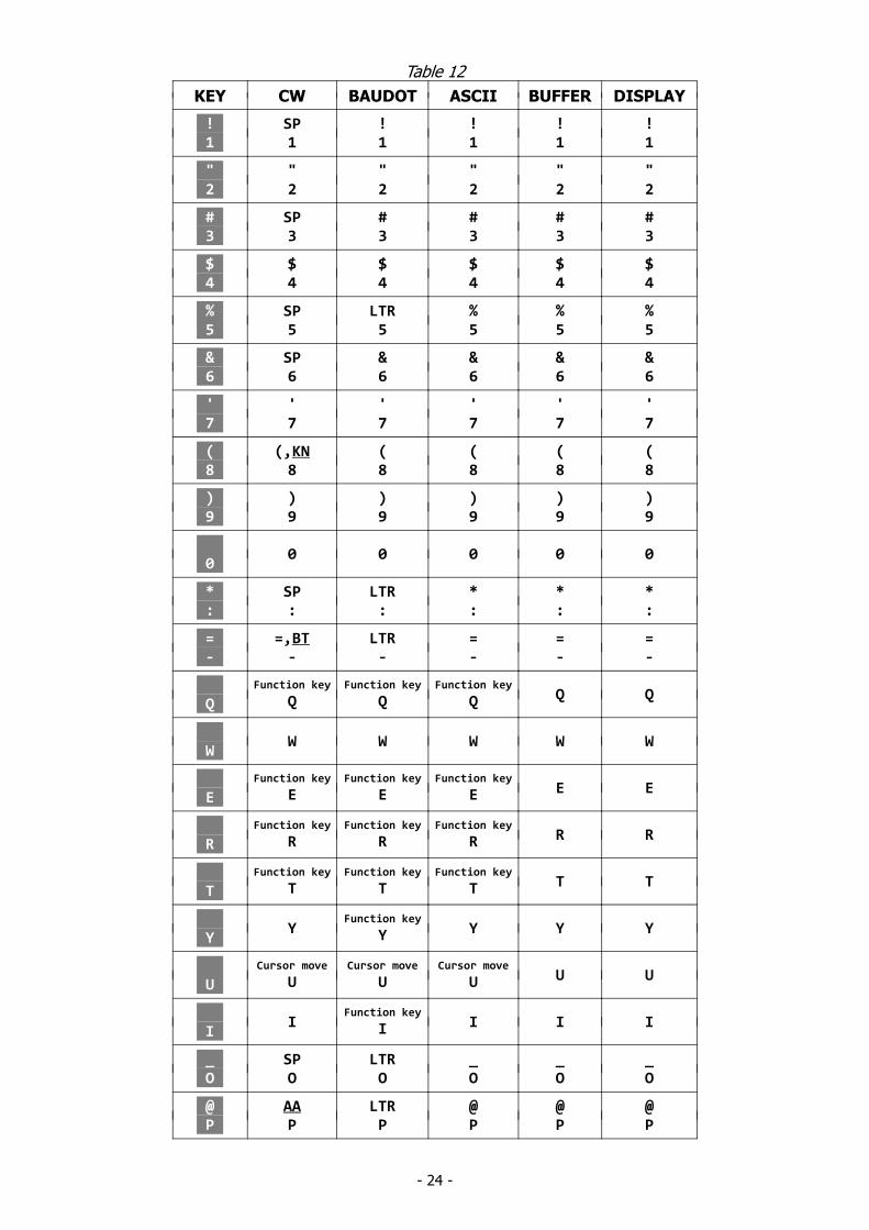
2. TransmissionOperate the keyboard, when characters corresponding to the respective keys asin Table 12 are displayed on the screen.
3. OUTPUT in-dicating LEDlights at
mark space space
4. The trans-mitting sound
heard heard heard
5. Setting The transceiver can be returned to the receiving state by any of the three waysbelow:a) Automatic with REMOTE terminal of the Θ-7000E when connected to PTTb) Manual terminal of the transceiver.c) Manual change by the switch on the transceiver
- 17 -
1. BUFFER MEMORY
Characters written in buffer memory are transmitted in order of writing. If the typing speed ex-ceeds the transmitting speed, characters are stored in the buffer memory up to 53 characters.With 53 characters being stored, the cursor disappears, gives a sound signal and inputs from thekey are rejected.
For loading of characters in the buffer memory SHIFT V . V will be displayed on the screen. To
release the loaded information, push these keys again.
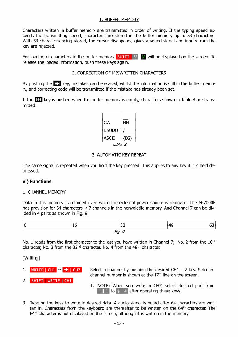
2. CORRECTION OF MISWRITTEN CHARACTERS
By pushing the HH key, mistakes can be erased, whilst the information is still in the buffer memo-
ry, and correcting code will be transmitted if the mistake has already been set.
If the HH key is pushed when the buffer memory is empty, characters shown in Table 8 are trans-
mitted:
CW__HH
BAUDOT /
ASCII BS
Table 8
3. AUTOMATIC KEY REPEAT
The same signal is repeated when you hold the key pressed. This applies to any key if it is held de-pressed.
vi) Functions
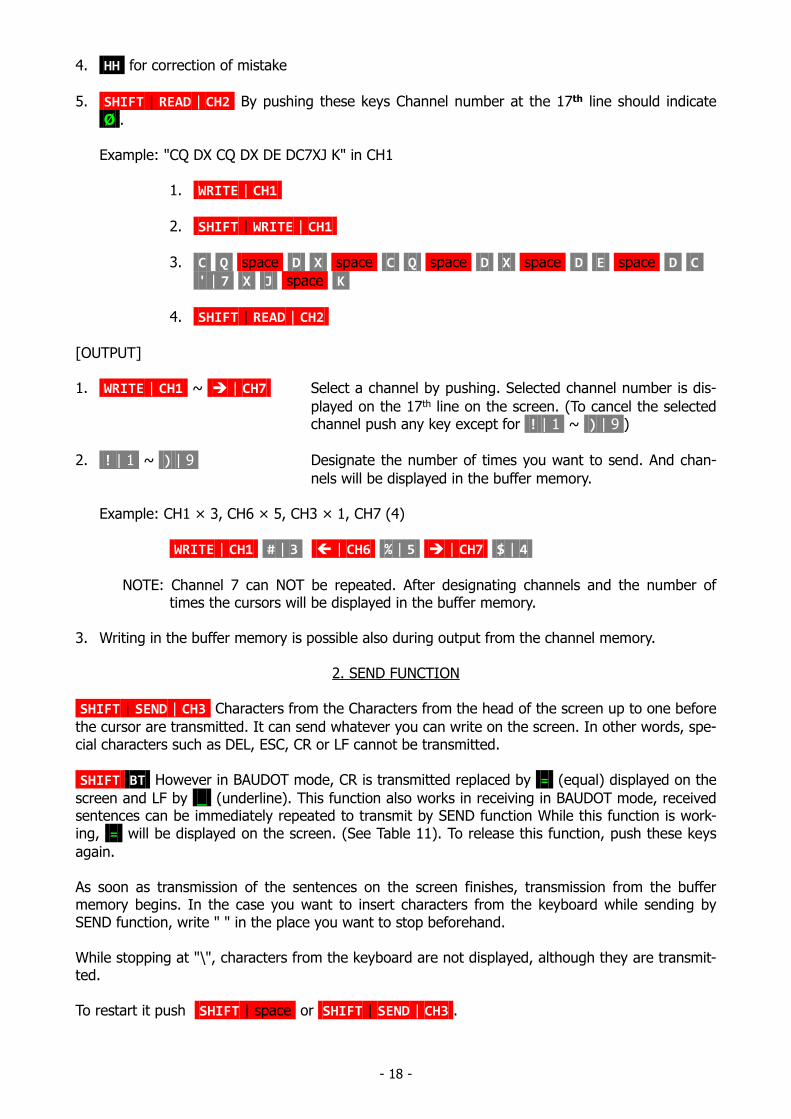
1. CHANNEL MEMORY
Data in this memory Is retained even when the external power source is removed. The Θ-7000Ehas provision for 64 characters × 7 channels in the nonvolatile memory. And Channel 7 can be div-ided in 4 parts as shown in Fig. 9.
0 16 32 48 63
Fig. 9
No. 1 reads from the first character to the last you have written in Channel 7; No. 2 from the 16th
character, No. 3 from the 32nd character, No. 4 from the 48th character.
[Writing]
1. WRITE | CH1 ~ | CH7
2. SHIFT | WRITE | CH1
Select a channel by pushing the desired CH1 – 7 key. Selectedchannel number is shown at the 17th line on the screen.
1. NOTE: When you write in CH7, select desired part from! | 1 to $ | 4 after operating these keys.
3. Type on the keys to write in desired data. A audio signal is heard after 64 characters are writ-ten in. Characters from the keyboard are thereafter to be written on the 64th character. The64th character is not displayed on the screen, although it is written in the memory.
- 18 -
4. HH for correction of mistake
5. SHIFT | READ | CH2 By pushing these keys Channel number at the 17th line should indicate
Ø .
Example: "CQ DX CQ DX DE DC7XJ K" in CH1
1. WRITE | CH1
2. SHIFT | WRITE | CH1
3. C Q space D X space C Q space D X space D E space D C
' | 7 X J space K
4. SHIFT | READ | CH2
[OUTPUT]
1. WRITE | CH1 ~ | CH7 Select a channel by pushing. Selected channel number is dis-
played on the 17th line on the screen. (To cancel the selectedchannel push any key except for ! | 1 ~ ) | 9 )
2. ! | 1 ~ ) | 9 Designate the number of times you want to send. And chan-
nels will be displayed in the buffer memory.
Example: CH1 × 3, CH6 × 5, CH3 × 1, CH7 (4)
WRITE | CH1 # | 3 | CH6 % | 5 | CH7 $ | 4
NOTE: Channel 7 can NOT be repeated. After designating channels and the number oftimes the cursors will be displayed in the buffer memory.
3. Writing in the buffer memory is possible also during output from the channel memory.
2. SEND FUNCTION
SHIFT | SEND | CH3 Characters from the Characters from the head of the screen up to one before
the cursor are transmitted. It can send whatever you can write on the screen. In other words, spe-cial characters such as DEL, ESC, CR or LF cannot be transmitted.
SHIFT BT However in BAUDOT mode, CR is transmitted replaced by = (equal) displayed on the
screen and LF by _ (underline). This function also works in receiving in BAUDOT mode, receivedsentences can be immediately repeated to transmit by SEND function While this function is work-ing, = will be displayed on the screen. (See Table 11). To release this function, push these keys
again.
As soon as transmission of the sentences on the screen finishes, transmission from the buffermemory begins. In the case you want to insert characters from the keyboard while sending bySEND function, write " " in the place you want to stop beforehand.
While stopping at "\", characters from the keyboard are not displayed, although they are transmit-ted.
To restart it push SHIFT | space or SHIFT | SEND | CH3 .
- 19 -
3. SPLIT SCREEN
SHIFT B The first page can be divided in two. The lower half works as a regular display. When
its space is filled, the information will be scrolled in the second page automatically. (NOTE: Thesecond page cannot be divided.)
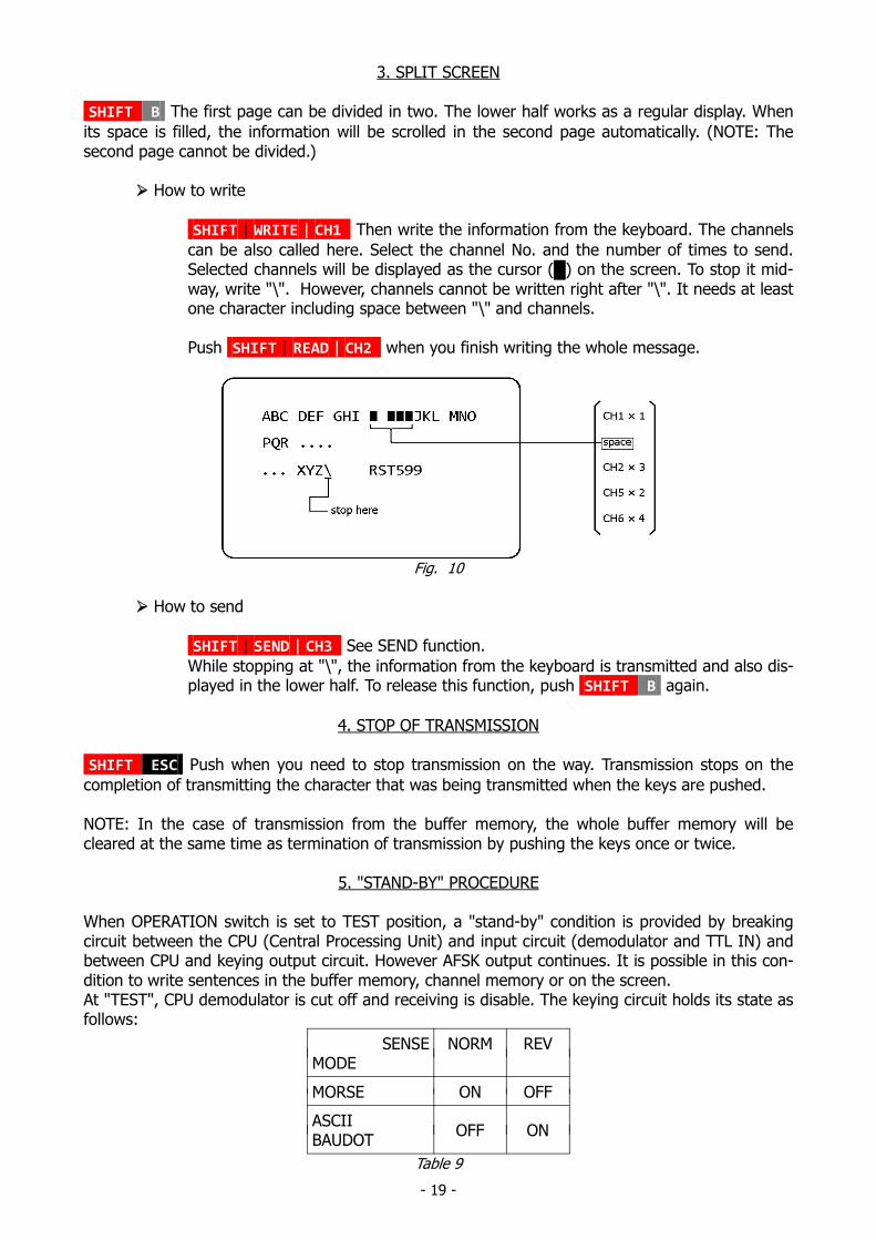
How to write
SHIFT | WRITE | CH1 Then write the information from the keyboard. The channels
can be also called here. Select the channel No. and the number of times to send.Selected channels will be displayed as the cursor () on the screen. To stop it mid-way, write "\". However, channels cannot be written right after "\". It needs at leastone character including space between "\" and channels.
Push SHIFT | READ | CH2 when you finish writing the whole message.
Fig. 10
How to send
SHIFT | SEND | CH3 See SEND function.
While stopping at "\", the information from the keyboard is transmitted and also dis-played in the lower half. To release this function, push SHIFT B again.
4. STOP OF TRANSMISSION
SHIFT ESC Push when you need to stop transmission on the way. Transmission stops on the
completion of transmitting the character that was being transmitted when the keys are pushed.
NOTE: In the case of transmission from the buffer memory, the whole buffer memory will becleared at the same time as termination of transmission by pushing the keys once or twice.
5. "STAND-BY" PROCEDURE
When OPERATION switch is set to TEST position, a "stand-by" condition is provided by breakingcircuit between the CPU (Central Processing Unit) and input circuit (demodulator and TTL IN) andbetween CPU and keying output circuit. However AFSK output continues. It is possible in this con-dition to write sentences in the buffer memory, channel memory or on the screen.At "TEST", CPU demodulator is cut off and receiving is disable. The keying circuit holds its state asfollows:
SENSEMODE
NORM REV
MORSE ON OFF
ASCIIBAUDOT
OFF ON
Table 9
- 20 -
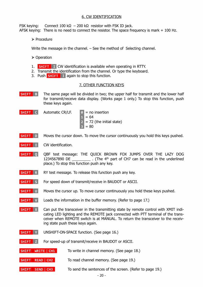
6. CW IDENTIFICATION
FSK keying: Connect 100 kΩ – 200 kΩ resistor with FSK ID jack.AFSK keying: There is no need to connect the resistor. The space frequency is mark + 100 Hz.
Procedure
Write the message in the channel. – See the method of Selecting channel.
Operation
1. SHIFT I CW identification is available when operating in RTTY.
2. Transmit the identification from the channel. Or type the keyboard.3. Push SHIFT I again to stop this function.
7. OTHER FUNCTION KEYS
SHIFT B The same page will be divided in two; the upper half for transmit and the lower half
for transmit/receive data display. (Works page 1 only.) To stop this function, pushthese keys again.
SHIFT C Automatic CR/LF. 0 = no insertion
1 = 64
2 = 72 (the initial state)
3 = 80
SHIFT D Moves the cursor down. To move the cursor continuously you hold this keys pushed.
SHIFT I CW identification.
SHIFT Q QBF test message: THE QUICK BROWN FOX JUMPS OVER THE LAZY DOG
1234567890 DE _________ . (The 4th part of CH7 can be read in the underlinedplace.) To stop this function push any key.
SHIFT R RY test message. To release this function push any key.
SHIFT S For speed down of transmit/receive in BAUDOT or ASCII.
SHIFT U Moves the cursor up. To move cursor continuously you hold these keys pushed.
SHIFT V Loads the information in the buffer memory. (Refer to page 17.)
SHIFT X Can put the transceiver in the transmitting state by remote control with XMIT indi-
cating LED lighting and the REMOTE jack connected with PTT terminal of the trans-ceiver when REMOTE switch is at MANUAL. To return the transceiver to the receiv-ing state push these keys again.
SHIFT Y UNSHIFT-ON-SPACE function. (See page 16.)
SHIFT Z For speed-up of transmit/receive in BAUDOT or ASCII.
SHIFT | WRITE | CH1 To write in channel memory. (See page 18.)
SHIFT | READ | CH2 To read channel memory. (See page 19.)
SHIFT | SEND | CH3 To send the sentences of the screen. (Refer to page 19.)
- 21 -
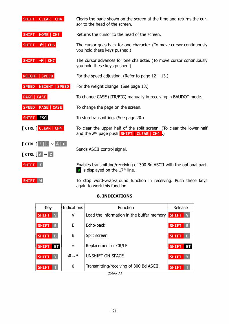
SHIFT | CLEAR | CH4 Clears the page shown on the screen at the time and returns the cur-
sor to the head of the screen.
SHIFT | HOME | CH5 Returns the cursor to the head of the screen.
SHIFT | | CH6 The cursor goes back for one character. (To move cursor continuously
you hold these keys pushed.)
SHIFT | | CH7 The cursor advances for one character. (To move cursor continuously
you hold these keys pushed.)
WEIGHT | SPEED For the speed adjusting. (Refer to page 12 – 13.)
SPEED | WEIGHT | SPEED For the weight change. (See page 13.)
PAGE | CASE To change CASE (LTR/FIG) manually in receiving in BAUDOT mode.
SPEED | PAGE | CASE To change the page on the screen.
SHIFT ESC To stop transmitting. (See page 20.)
[ CTRL ] CLEAR | CH4 To clear the upper half of the split screen. (To clear the lower half
and the 2nd page push SHIFT | CLEAR | CH4 .)
[ CTRL ] ! | 1 ~ & | 6
Sends ASCII control signal.[ CTRL ] A ~ Z
SHIFT T Enables transmitting/receiving of 300 Bd ASCII with the optional part.
0 is displayed on the 17th line.
SHIFT W To stop word-wrap-around function in receiving. Push these keys
again to work this function.
8. INDICATIONS
Key Indications Function Release
SHIFT V
SHIFT E
SHIFT B
SHIFT BT
SHIFT Y
SHIFT T
V
E
B
=
#→*
0
Load the information in the buffer memory
Echo-back
Split screen
Replacement of CR/LF
UNSHIFT-ON-SPACE
Transmitting/receiving of 300 Bd ASCII
SHIFT V
SHIFT E
SHIFT B
SHIFT BT
SHIFT Y
SHIFT T
Table 11

- 22 -
CW practice
1. Connect a hand key with TTL LEVEL IN jack on the back panel.2. Set MODE switch to MORSE, OPERATION switch to NORM and INPUT switch at
TTL.3. Manipulate the key and reading is gained and displayed on the screen.4. Keying output turns ON and OFF corresponding to the working of key. For moni-
toring the transmitting sound push SHIFT E .
vii) Using a tape recorder for storage ("paper tape")
[1] As an external memory for transmitting
* Sentence Recording *
1. Set the mode and speed2. Set GAIN control of the back panel to the medium level in order to prevent excess input
to a tape recorder.3. Put the recorder in recording condition, leave it run for several seconds so as to get
feed.4. Send whatever you want to record from the Θ-7000E.5. After sending out sentences, let it run for several seconds so as to get feed then stop it.
* Transmitting with SEND function *
1. Set the mode and speed as recorded in the tape recorder.2. Clear the screen.3. Adjust the volume of the tape recorder to make output level about 1 VPP when con-
nected. The tone adjustment should be at high at this time.4. Sentences are read and displayed on the screen when playback starts.5. Set the switches on the front panel to the proper positions.
* Transmitting with ECHO-BACK function *
SHIFT E and operate the tape recorder in play back. In this way a cassette tape can be
used as paper tape of telex. To stop this function push these keys again.
[2] Receding of received signals
For recording signals during receiving
with PHONE jack Recording is enabled by connecting PHONE jack of the Θ-7000E withthe microphone terminal of a tape recorder.
or
SHIFT E Connect the microphone terminal of a tape recorder with AFSK OUT
TAPE jack of the Θ-7000E. E is displayed on the screen.
- 23 -
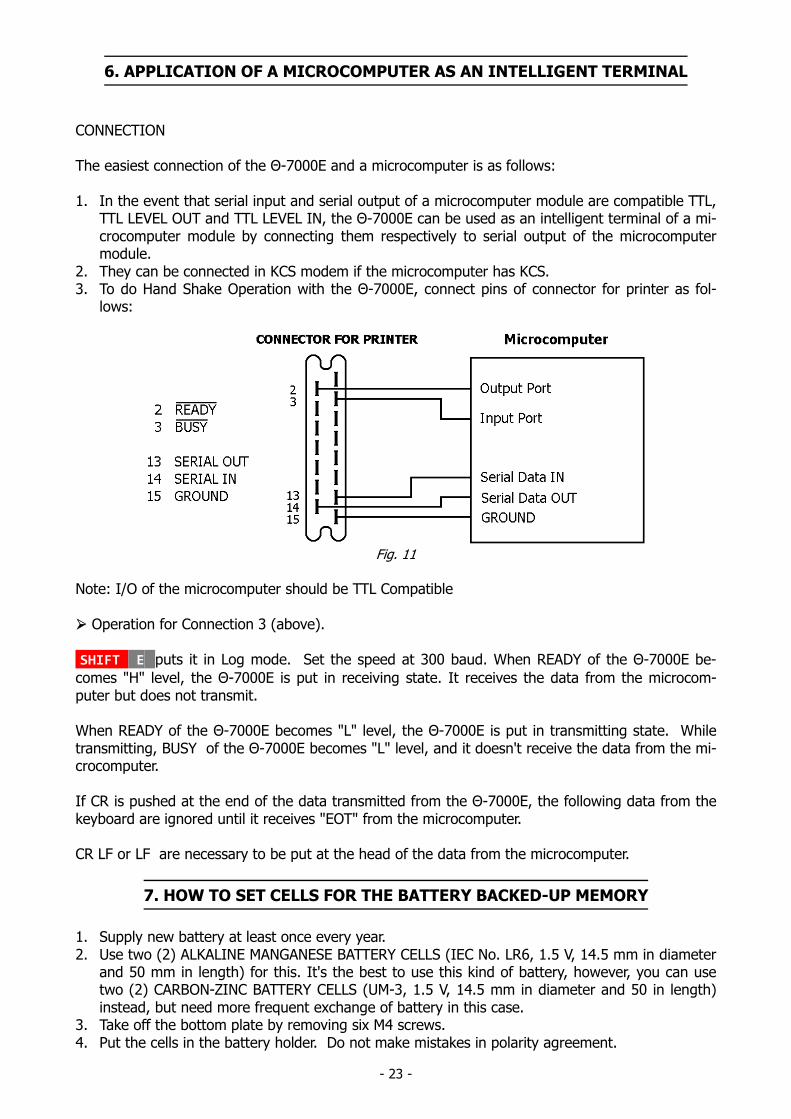
6. APPLICATION OF A MICROCOMPUTER AS AN INTELLIGENT TERMINAL
CONNECTION
The easiest connection of the Θ-7000E and a microcomputer is as follows:
1. In the event that serial input and serial output of a microcomputer module are compatible TTL,TTL LEVEL OUT and TTL LEVEL IN, the Θ-7000E can be used as an intelligent terminal of a mi-crocomputer module by connecting them respectively to serial output of the microcomputermodule.
2. They can be connected in KCS modem if the microcomputer has KCS.3. To do Hand Shake Operation with the Θ-7000E, connect pins of connector for printer as fol-
lows:
Fig. 11
Note: I/O of the microcomputer should be TTL Compatible
Operation for Connection 3 (above).
SHIFT E puts it in Log mode. Set the speed at 300 baud. When READY of the Θ-7000E be-
comes "H" level, the Θ-7000E is put in receiving state. It receives the data from the microcom-puter but does not transmit.
When READY of the Θ-7000E becomes "L" level, the Θ-7000E is put in transmitting state. Whiletransmitting, BUSY of the Θ-7000E becomes "L" level, and it doesn't receive the data from the mi-crocomputer.
If CR is pushed at the end of the data transmitted from the Θ-7000E, the following data from thekeyboard are ignored until it receives "EOT" from the microcomputer.
CR LF or LF are necessary to be put at the head of the data from the microcomputer.
7. HOW TO SET CELLS FOR THE BATTERY BACKED-UP MEMORY
1. Supply new battery at least once every year.2. Use two (2) ALKALINE MANGANESE BATTERY CELLS (IEC No. LR6, 1.5 V, 14.5 mm in diameter
and 50 mm in length) for this. It's the best to use this kind of battery, however, you can usetwo (2) CARBON-ZINC BATTERY CELLS (UM-3, 1.5 V, 14.5 mm in diameter and 50 in length)instead, but need more frequent exchange of battery in this case.
3. Take off the bottom plate by removing six M4 screws.4. Put the cells in the battery holder. Do not make mistakes in polarity agreement.
- 24 -
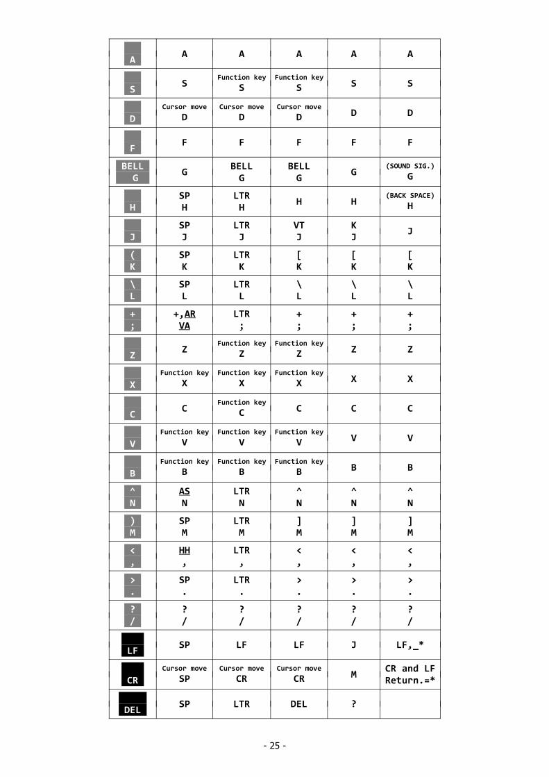
Table 12
KEY CW BAUDOT ASCII BUFFER DISPLAY
! 1
SP1
!1
!1
!1
!1
" 2
"2
"2
"2
"2
"2
# 3
SP3
#3
#3
#3
#3
$ 4
$4
$4
$4
$4
$4
% 5
SP5
LTR5
%5
%5
%5
& 6
SP6
&6
&6
&6
&6
' 7
'7
'7
'7
'7
'7
( 8
(,KN8
(8
(8
(8
(8
) 9
)9
)9
)9
)9
)9
0 0 0 0 0 0
* :
SP:
LTR:
*:
*:
*:
= -
=,BT-
LTR-
=-
=-
=-
Q
Function key
QFunction key
QFunction key
Q Q Q
W W W W W W
E
Function key
EFunction key
EFunction key
E E E
R
Function key
RFunction key
RFunction key
R R R
T
Function key
TFunction key
TFunction key
T T T
Y Y
Function key
Y Y Y Y
U
Cursor move
UCursor move
UCursor move
U U U
I I
Function key
I I I I
_ O
SPO
LTRO
_O
_O
_O
@ P
AAP
LTRP
@P
@P
@P
- 25 -
A A A A A A
S S
Function key
SFunction key
S S S
D
Cursor move
DCursor move
DCursor move
D D D
F F F F F F
BELL G
GBELLG
BELLG
G(SOUND SIG.)
G
H SPH
LTRH
H H(BACK SPACE)
H
J SPJ
LTRJ
VTJ
KJ
J
( K
SPK
LTRK
[K
[K
[K
\ L
SPL
LTRL
\L
\L
\L
+ ;
+,ARVA
LTR;
+;
+;
+;
Z Z
Function key
ZFunction key
Z Z Z
X
Function key
XFunction key
XFunction key
X X X
C C
Function key
C C C C
V
Function key
VFunction key
VFunction key
V V V
B
Function key
BFunction key
BFunction key
B B B
^ N
ASN
LTRN
^N
^N
^N
) M
SPM
LTRM
]M
]M
]M
< ,
HH,
LTR,
<,
<,
<,
> .
SP.
LTR.
>.
>.
>.
? /
?/
?/
?/
?/
?/
LF SP LF LF J LF,_*
CR
Cursor move
SPCursor move
CRCursor move
CR MCR and LFReturn.=*
DEL SP LTR DEL ?
- 26 -
ESC STOP XMIT
SPSTOP XMIT
LTRSTOP XMIT
ESC[
__ BT
BT, =Function key
LTR = = =
__ KN
KN,( ( ( ( (
__ HH
HH / BS <,/,H <,/,BS
SPACE BAR
Function key
SPFunction key
SPFunction key
SP SP SP
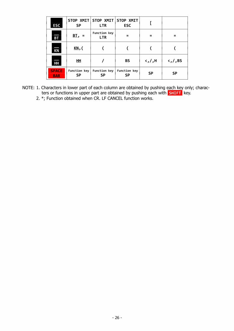
NOTE: 1. Characters in lower part of each column are obtained by pushing each key only; charac- ters or functions in upper part are obtained by pushing each with SHIFT key.
2. *; Function obtained when CR. LF CANCEL function works.
- 27 -
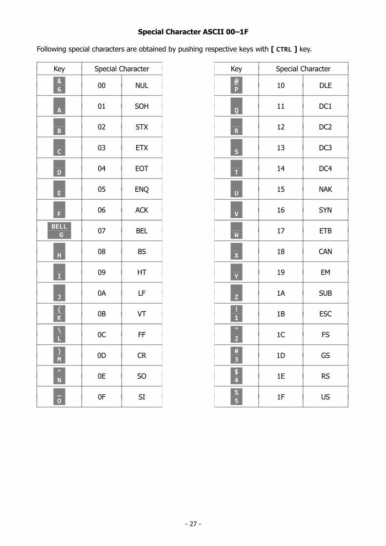
Special Character ASCII 00–1F
Following special characters are obtained by pushing respective keys with [ CTRL ] key.
Key Special Character Key Special Character
& 6
00 NUL @ P
10 DLE
A 01 SOH
Q 11 DC1
B 02 STX
R 12 DC2
C 03 ETX
S 13 DC3
D 04 EOT
T 14 DC4
E 05 ENQ
U 15 NAK
F 06 ACK
V 16 SYN
BELL G
07 BEL W
17 ETB
H 08 BS
X 18 CAN
I 09 HT
Y 19 EM
J 0A LF
Z 1A SUB
( K
0B VT ! 1
1B ESC
\ L
0C FF " 2
1C FS
) M
0D CR # 3
1D GS
^ N
0E SO $ 4
1E RS
_ O
0F SI % 5
1F US
- 28 -
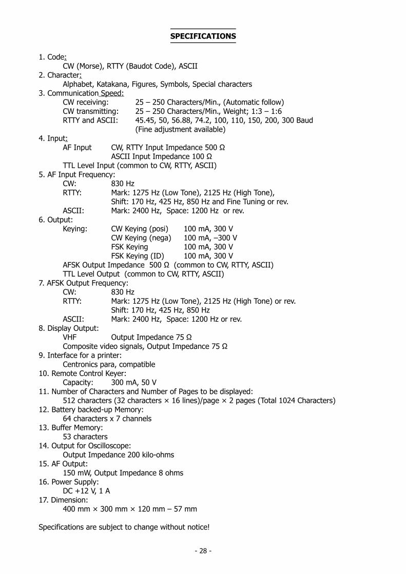
SPECIFICATIONS
1. Code:CW (Morse), RTTY (Baudot Code), ASCII
2. Character:Alphabet, Katakana, Figures, Symbols, Special characters
3. Communication Speed:CW receiving: 25 – 250 Characters/Min., (Automatic follow)CW transmitting: 25 – 250 Characters/Min., Weight; 1:3 – 1:6RTTY and ASCII: 45.45, 50, 56.88, 74.2, 100, 110, 150, 200, 300 Baud
(Fine adjustment available)4. Input:
AF Input CW, RTTY Input Impedance 500 ΩASCII Input Impedance 100 Ω
TTL Level Input (common to CW, RTTY, ASCII)5. AF Input Frequency:
CW: 830 HzRTTY: Mark: 1275 Hz (Low Tone), 2125 Hz (High Tone),
Shift: 170 Hz, 425 Hz, 850 Hz and Fine Tuning or rev.ASCII: Mark: 2400 Hz, Space: 1200 Hz or rev.
6. Output:Keying: CW Keying (posi) 100 mA, 300 V
CW Keying (nega) 100 mA, –300 VFSK Keying 100 mA, 300 VFSK Keying (ID) 100 mA, 300 V
AFSK Output Impedance 500 Ω (common to CW, RTTY, ASCII)TTL Level Output (common to CW, RTTY, ASCII)
7. AFSK Output Frequency:CW: 830 HzRTTY: Mark: 1275 Hz (Low Tone), 2125 Hz (High Tone) or rev.
Shift: 170 Hz, 425 Hz, 850 HzASCII: Mark: 2400 Hz, Space: 1200 Hz or rev.
8. Display Output:VHF Output Impedance 75 ΩComposite video signals, Output Impedance 75 Ω
9. Interface for a printer:Centronics para, compatible
10. Remote Control Keyer:Capacity: 300 mA, 50 V
11. Number of Characters and Number of Pages to be displayed:512 characters (32 characters × 16 lines)/page × 2 pages (Total 1024 Characters)
12. Battery backed-up Memory:64 characters x 7 channels
13. Buffer Memory:53 characters
14. Output for Oscilloscope:Output Impedance 200 kilo-ohms
15. AF Output:150 mW, Output Impedance 8 ohms
16. Power Supply:DC +12 V, 1 A
17. Dimension:400 mm × 300 mm × 120 mm – 57 mm
Specifications are subject to change without notice!
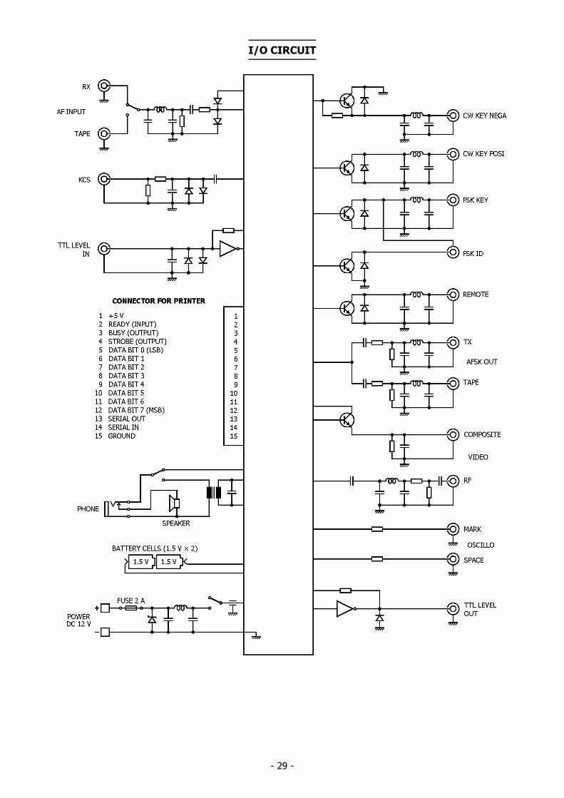
- 29 -
I/O CIRCUIT