Climate Chamber With Fast Humidity And Temperature ... · PDF filefor Small-angle Neutron...
25
WIR SCHAFFEN WISSEN – HEUTE FÜR MORGEN Climate Chamber with Fast Humidity and Temperature Response for Small-angle Neutron Scattering Lothar Holitzner :: Designing Engineer :: Paul Scherrer Institut .
-
Upload
truongcong -
Category
Documents
-
view
218 -
download
2
Transcript of Climate Chamber With Fast Humidity And Temperature ... · PDF filefor Small-angle Neutron...
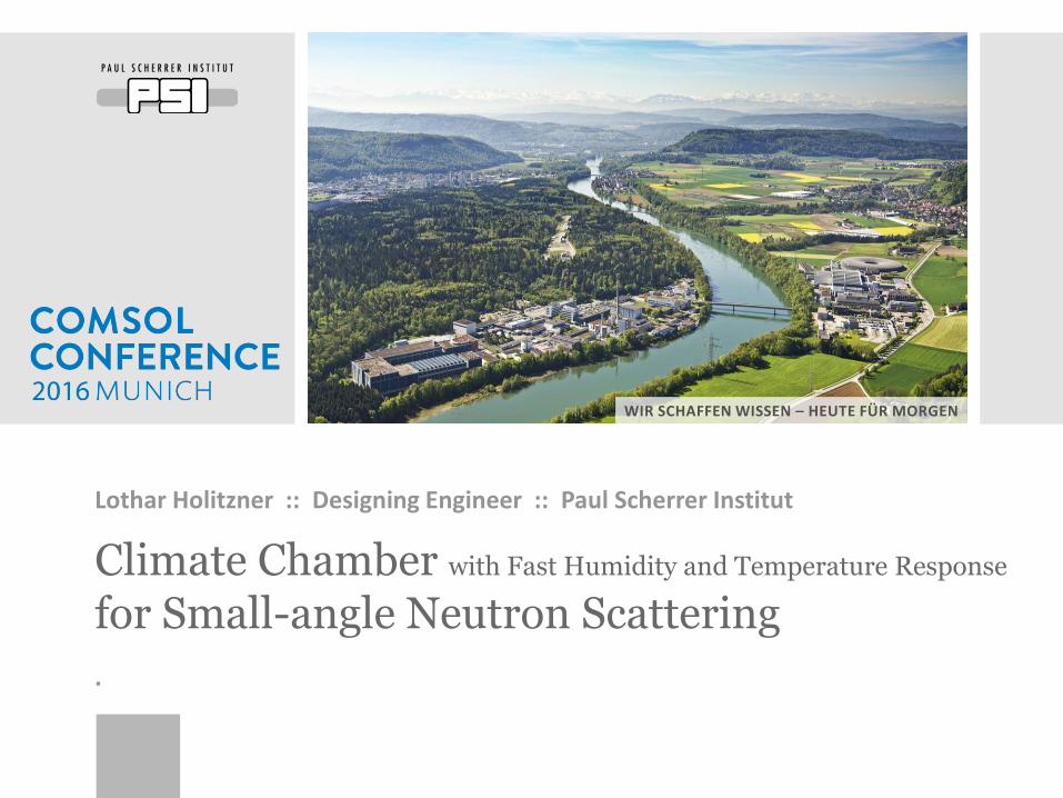
WIR SCHAFFEN WISSEN – HEUTE FÜR MORGEN
Climate Chamber with Fast Humidity and Temperature Response
for Small-angle Neutron Scattering
Lothar Holitzner :: Designing Engineer :: Paul Scherrer Institut
.
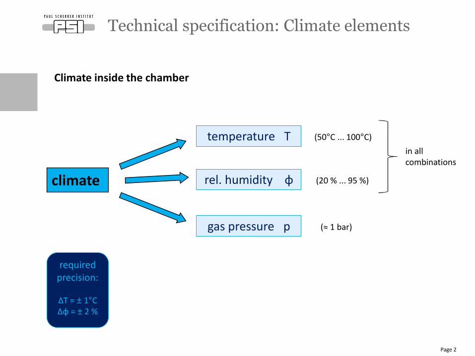
Climate inside the chamber
.
Technical specification: Climate elements
Page 2
climate
temperature T
rel. humidity φ
gas pressure p
(20 % ... 95 %)
(≈ 1 bar)
in all combinations
(50°C ... 100°C)
requiredprecision:
∆T = ± 1°C∆φ = ± 2 %
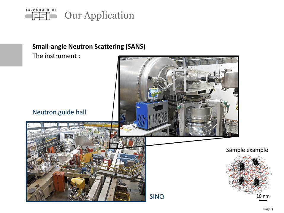
Small-angle Neutron Scattering (SANS)
The instrument :
Neutron guide hall
Sample example
SINQ
Our Application
Page 3
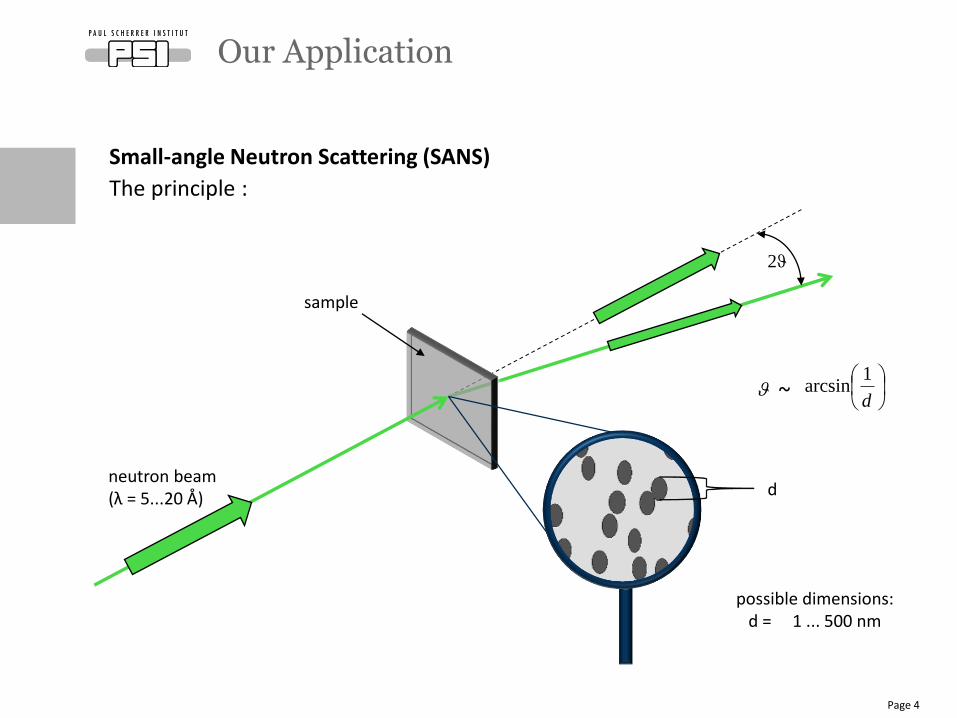
Small-angle Neutron Scattering (SANS)
The principle :
Our Application
Page 4
neutron beam(λ = 5...20 Å)
sample
2ϑ
possible dimensions: d = 1 ... 500 nm
d
d
1arcsin~
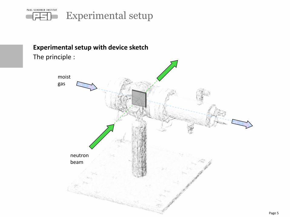
Experimental setup with device sketch
The principle :
Experimental setup
Page 5
moist gas
neutron beam
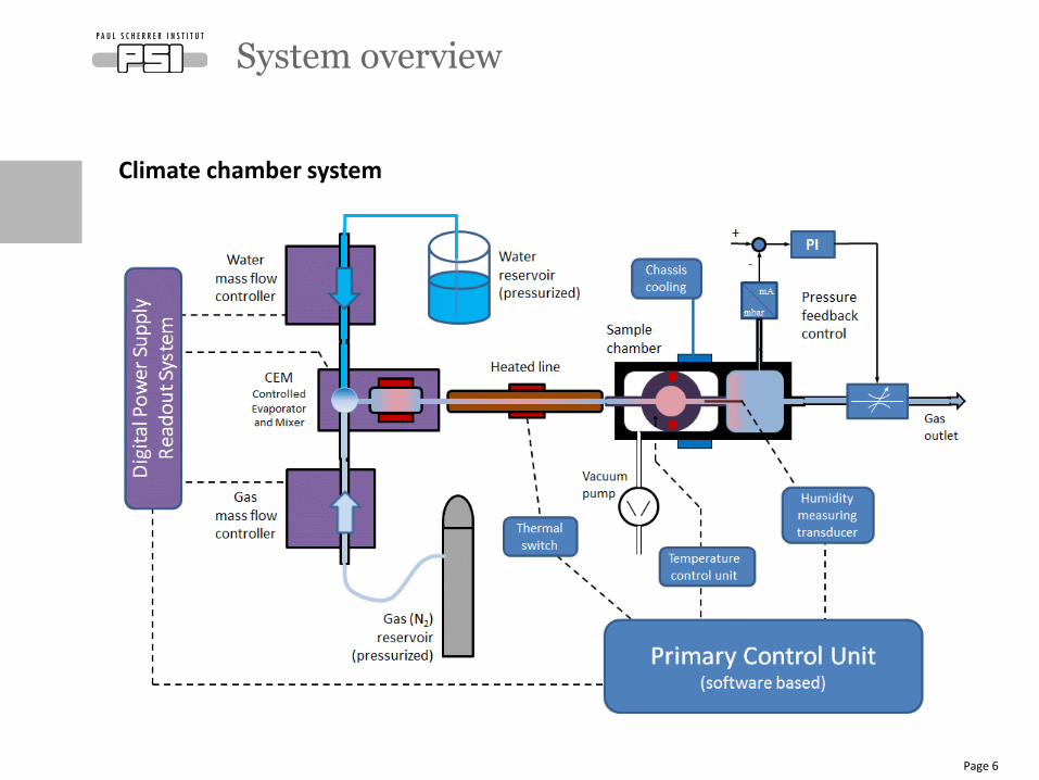
System overview
Page 6
Climate chamber system
Operation overview
Page 7
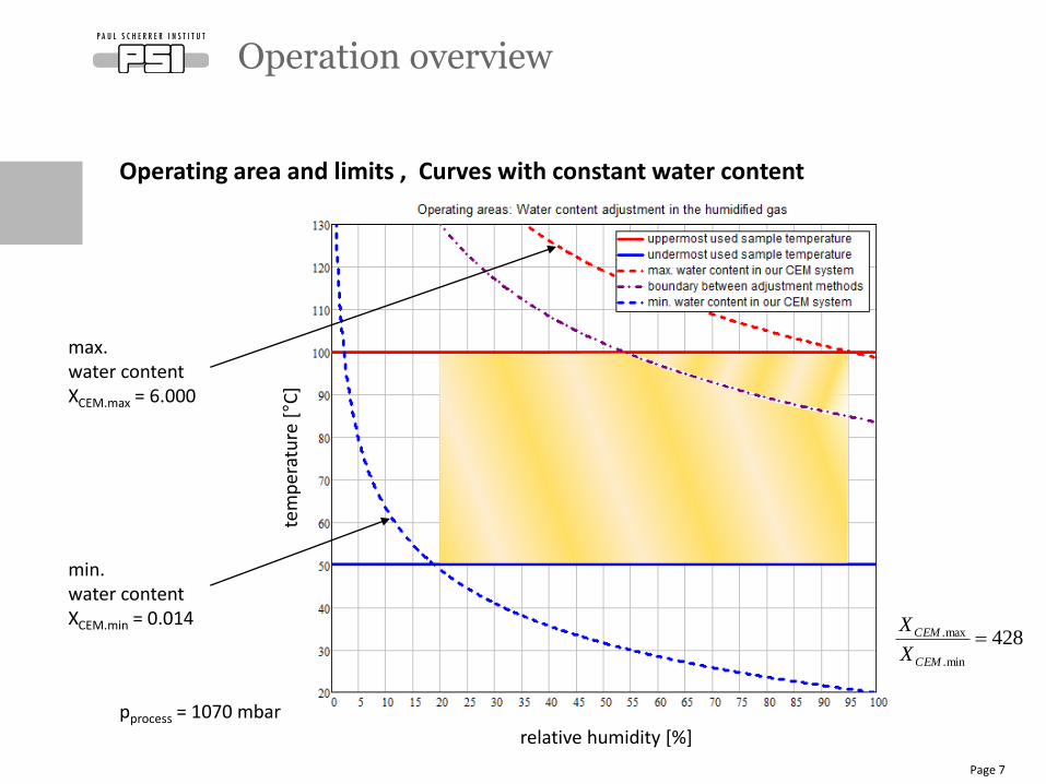
max. water content XCEM.max = 6.000
min. water content XCEM.min = 0.014
relative humidity [%]
tem
per
atu
re [°C
]
428min.
max. CEM
CEM
X
X
Operating area and limits , Curves with constant water content
pprocess = 1070 mbar
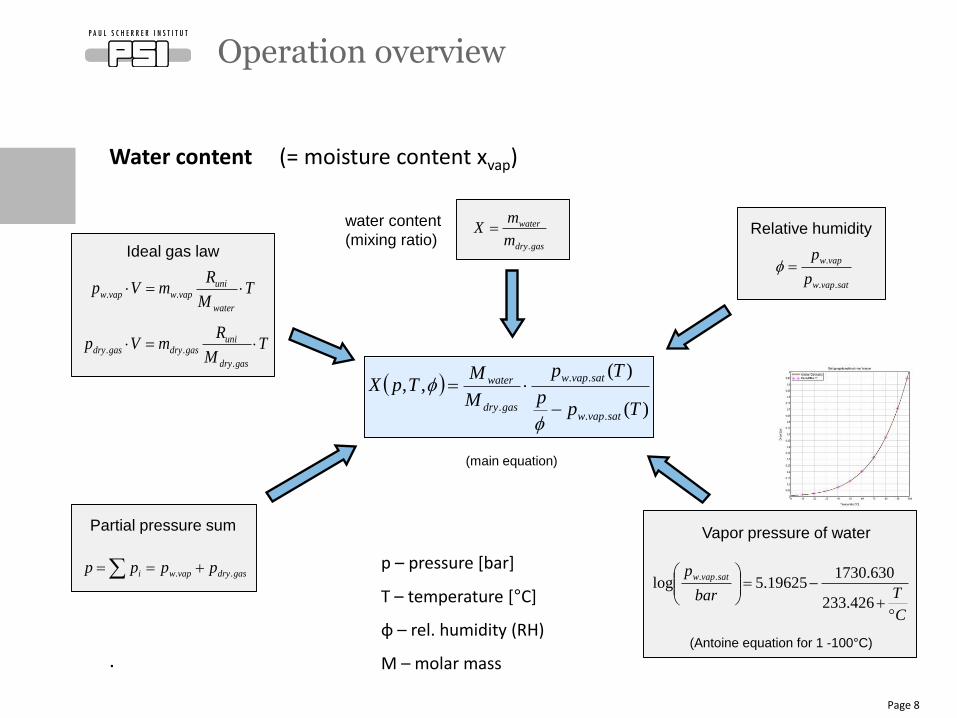
Water content (= moisture content xvap)
.
Operation overview
Page 8
water content
(mixing ratio)
)(
)(,,
..
..
. Tpp
Tp
M
MTpX
satvapw
satvapw
gasdry
water
Ideal gas law
TM
RmVp
water
univapwvapw ..
TM
RmVp
gasdry
unigasdrygasdry
.
..
Partial pressure sum
gasdryvapwi pppp ..
Vapor pressure of water
C
Tbar
p satvapw
426.233
630.173019625.5log
..
(Antoine equation for 1 -100°C)
Relative humidity
satvapw
vapw
p
p
..
.
gasdry
water
m
mX
.
(main equation)
p – pressure [bar]
T – temperature [°C]
φ – rel. humidity (RH)
M – molar mass
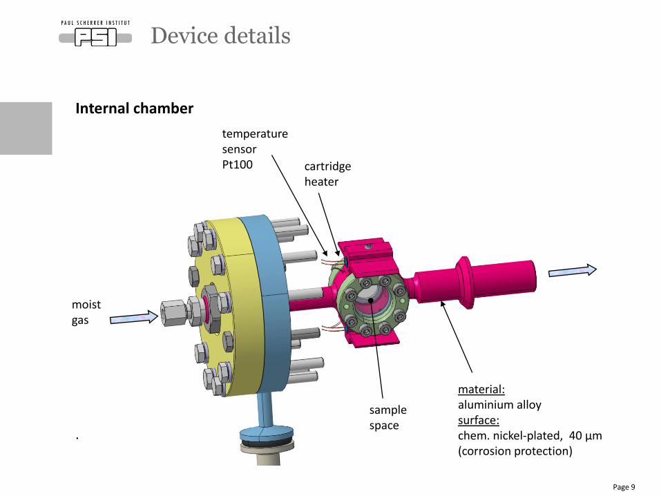
Internal chamber
.
Device details
Page 9
cartridge heater
moist gas
material: aluminium alloy surface: chem. nickel-plated, 40 μm (corrosion protection)
temperature sensor Pt100
sample space
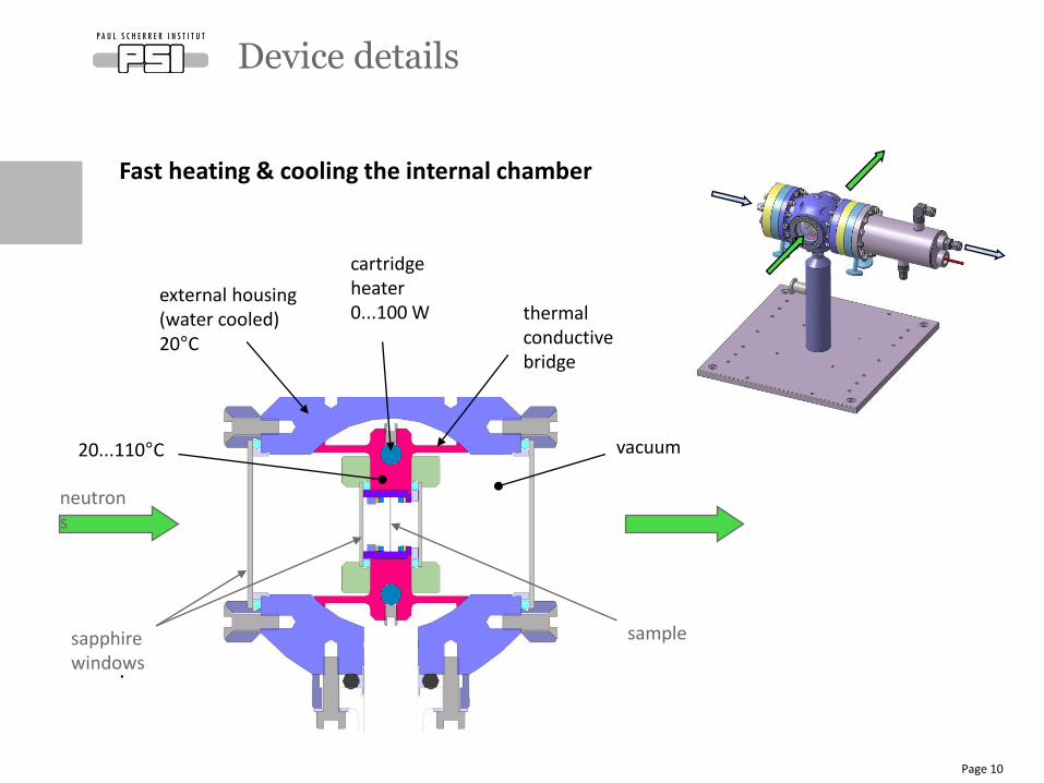
Fast heating & cooling the internal chamber
.
Device details
Page 10
sample
neutrons
vacuum
thermal conductive bridge
cartridge heater0...100 W
external housing (water cooled)20°C
sapphire windows
20...110°C
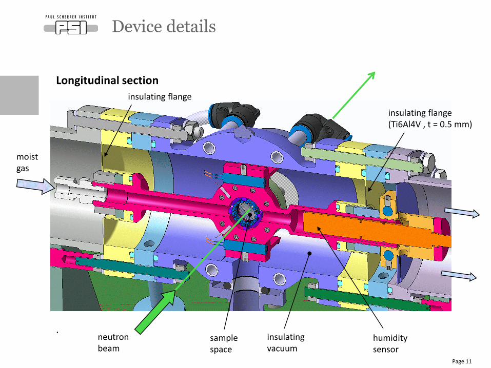
Device details
Page 11
moist gas
neutron beam
Longitudinal section
.
insulating flange (Ti6Al4V , t = 0.5 mm)
insulating vacuum
humidity sensor
sample space
insulating flange
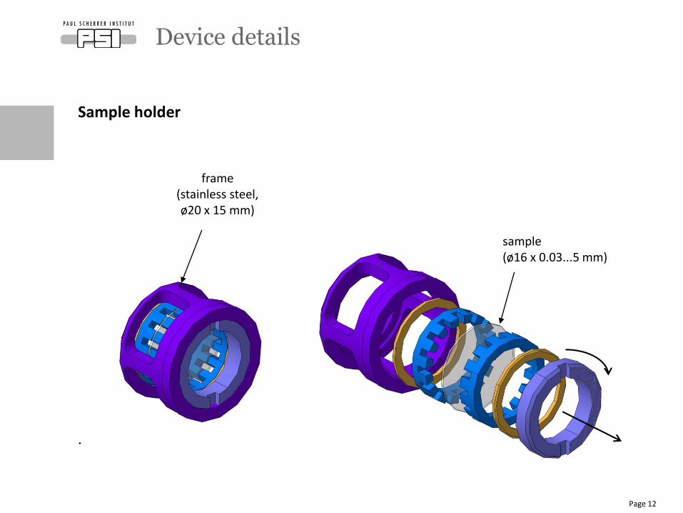
Sample holder
.
Device details
Page 12
frame (stainless steel, ø20 x 15 mm)
sample (ø16 x 0.03...5 mm)
Our goals:
❶ Gas flow distribution
near the sample surface: as uniform as possible
❷ Climate precision: temperature ∆T = ± 1°C
rel. humidity ∆φ = ± 2 %
❸ Change of temperature: time constants Theating ≈ Tcooling
→ improved temperature controllability
❹ Change of climate: as fast as possible
Design criteria
Page 13
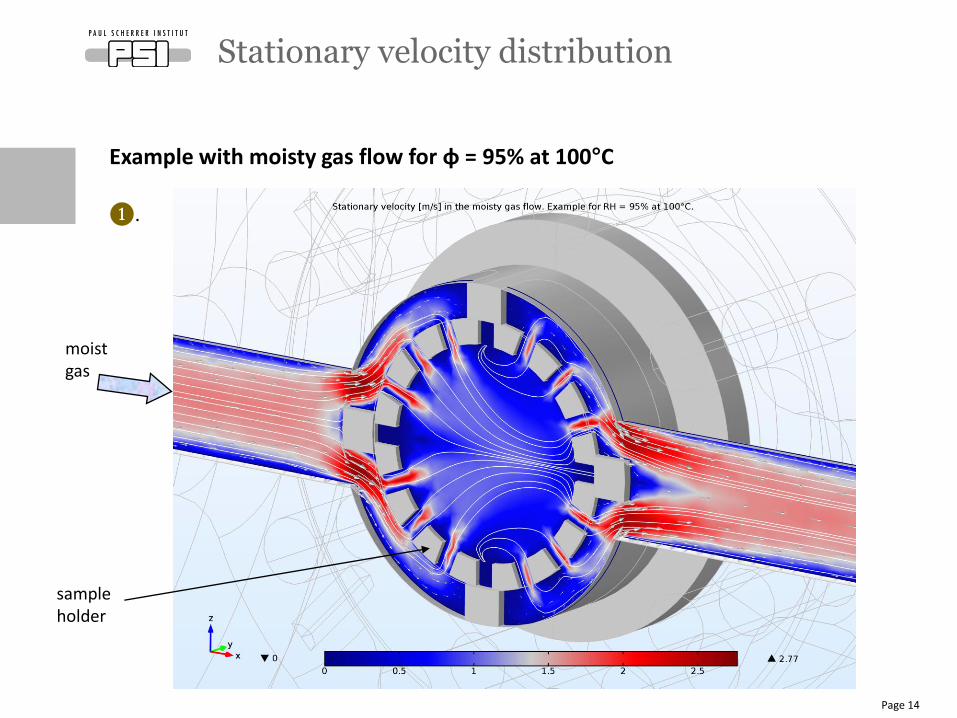
Stationary velocity distribution
Page 14
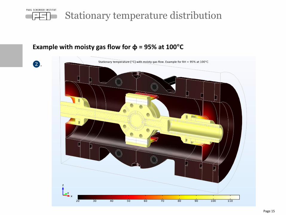
Example with moisty gas flow for φ = 95% at 100°C
❶.
sampleholder
moist gas
Example with moisty gas flow for φ = 95% at 100°C
❷.
Stationary temperature distribution
Page 15
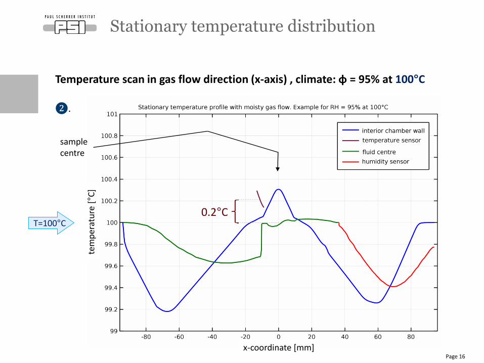
Temperature scan in gas flow direction (x-axis) , climate: φ = 95% at 100°C
❷.
Stationary temperature distribution
Page 16
T=100°C0.2°C
sample centre
tem
per
atu
re [°C
]
x-coordinate [mm]
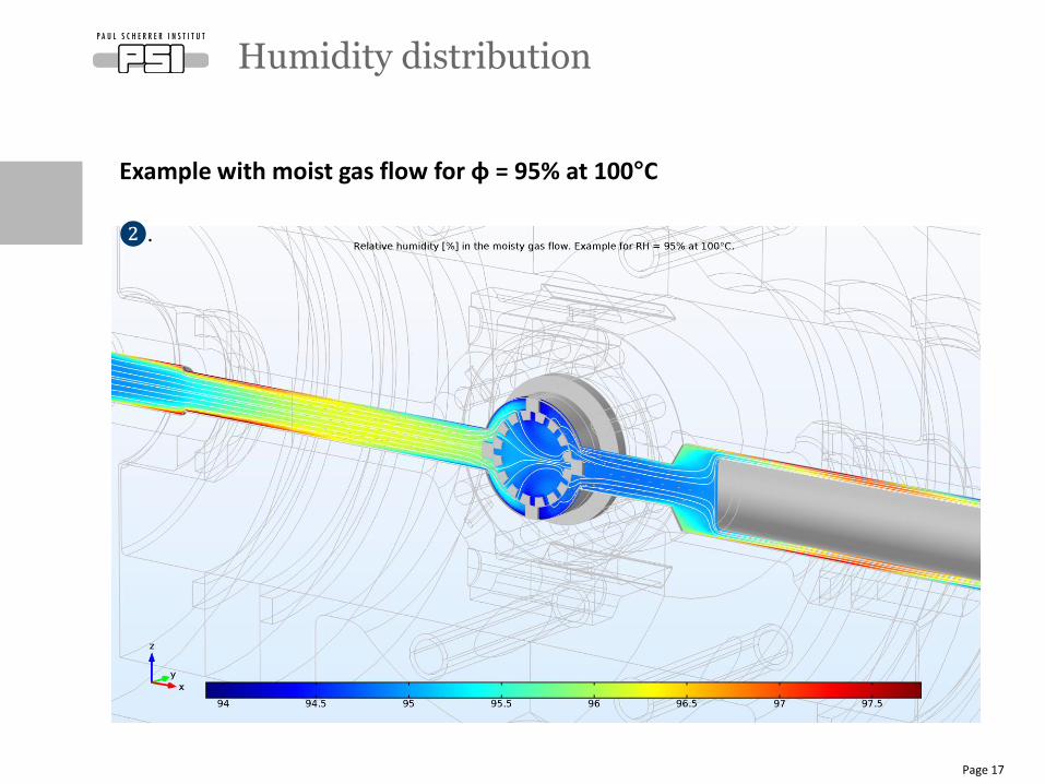
Humidity distribution
Page 17
Example with moist gas flow for φ = 95% at 100°C
❷.
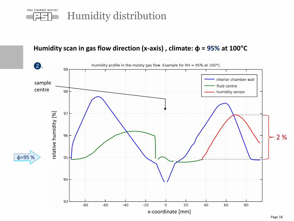
Humidity scan in gas flow direction (x-axis) , climate: φ = 95% at 100°C
❷.
Humidity distribution
Page 18
rela
tive
hu
mid
ity
[%]
φ=95 %
sample centre
2 %
x-coordinate [mm]
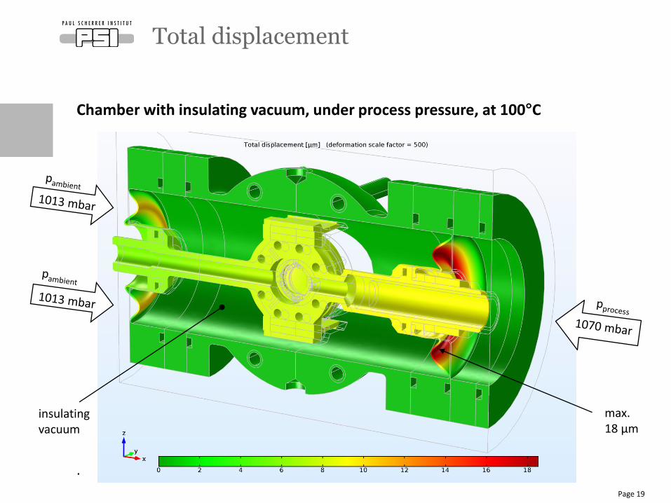
Chamber with insulating vacuum, under process pressure, at 100°C
.
Total displacement
Page 19
insulating vacuum
max. 18 μm
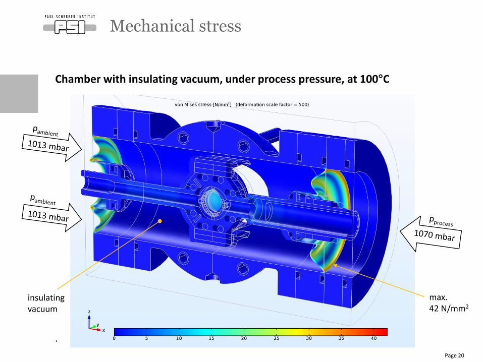
Chamber with insulating vacuum, under process pressure, at 100°C
.
Mechanical stress
Page 20
insulating vacuum
max. 42 N/mm2
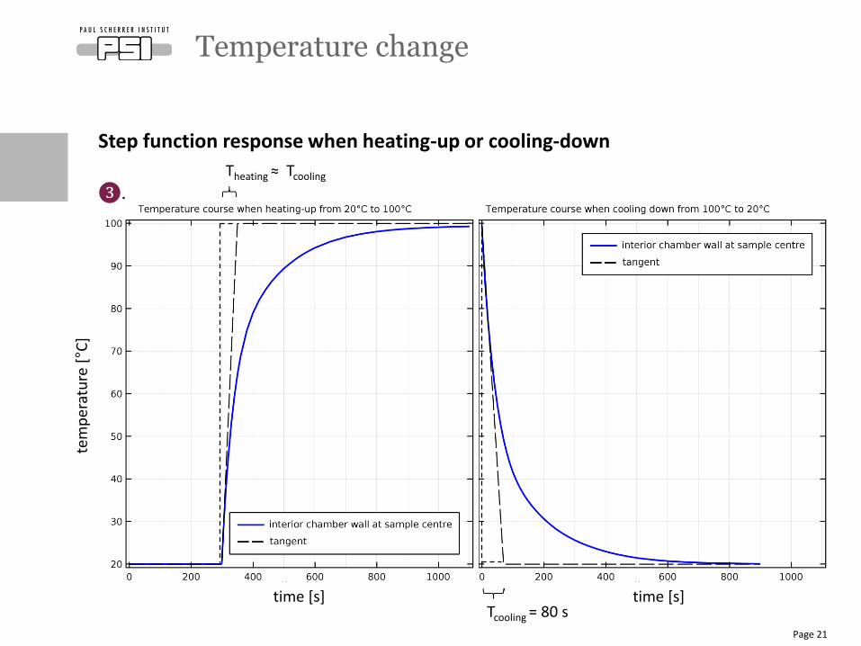
Temperature change
Page 21
Tcooling = 80 s
Step function response when heating-up or cooling-down
❸.Theating ≈ Tcooling
tem
per
atu
re [°C
]
time [s] time [s]
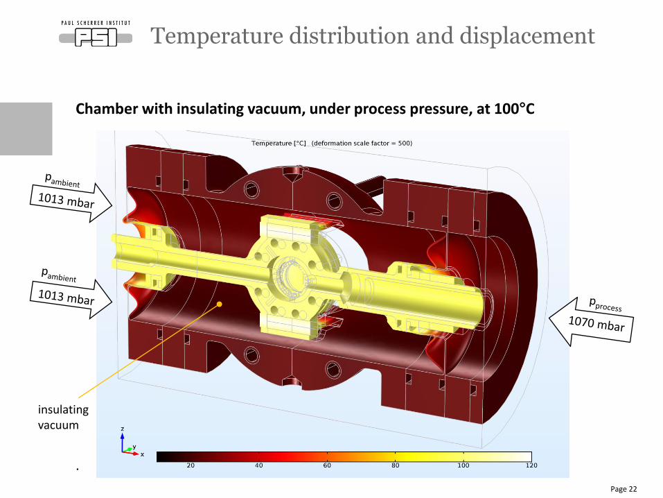
Chamber with insulating vacuum, under process pressure, at 100°C
.
Temperature distribution and displacement
Page 22
insulating vacuum
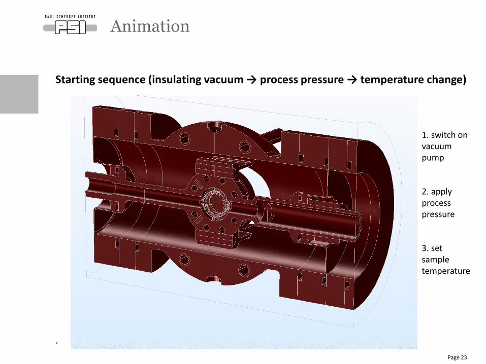
Starting sequence (insulating vacuum → process pressure → temperature change)
.
Animation
Page 23
1. switch on vacuum pump
2. applyprocess pressure
3. set sample temperature
Page 24
Wir schaffen Wissen – heute für morgen
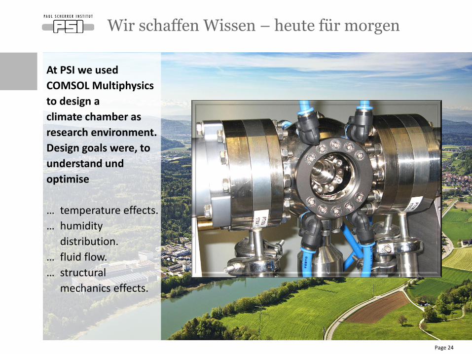
At PSI we used
COMSOL Multiphysics
to design a
climate chamber as
research environment.
Design goals were, to
understand und
optimise
… temperature effects.
… humidity
distribution.
… fluid flow.
… structural
mechanics effects.
Page 25
Wir schaffen Wissen – heute für morgen
My thanks go to
• Dr. Lorenz Gubler 1)
• Dr. Urs Gasser 2)
• Raphael Müller 3)
• Jan Krebs 3)
• Gioacchio Cristallo 4)
• Roger Stefani 4)
• Juerg Thut 1)
• Manuel Lehmann 3)
• Philipp Looser 3)
1) Electrochemistry Lab.
(LEC)2) Neutron Scattering Lab.
(LNS)3) Scientific Develop. Lab.
(LDM)4) PSI Mech. Prod. (AMI)