CISC Steel Design Series 2 Bolt Groups Subjected to an Eccentric and Inclined Point Load CANADIAN...
20
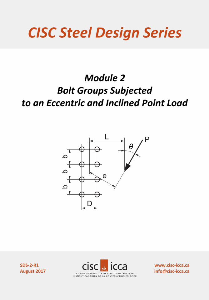
Module 2 Bolt Groups Subjected to an Eccentric and Inclined Point Load CANADIAN INSTITUTE OF STEEL CONSTRUCTION INSTITUT CANADIEN DE LA CONSTRUCTION EN ACIER CISC Steel Design Series www.cisc-icca.ca [email protected] SDS-2-R1 August 2017 e P L b b b D θ
Transcript of CISC Steel Design Series 2 Bolt Groups Subjected to an Eccentric and Inclined Point Load CANADIAN...
Module 2 Bolt Groups Subjected
to an Eccentric and Inclined Point Load
CANADIAN INSTITUTE OF STEEL CONSTRUCTIONINSTITUT CANADIEN DE LA CONSTRUCTION EN ACIER
CISC Steel Design Series
SDS-2-R1August 2017
e
PL
bb
b
D
θ
Copyright © 2017
Canadian Institute of Steel Construction
CISC Steel Design Series SDS-2-R1
July 2017
Revised August 2017
ISBN 978-0-88811-213-2
All rights reserved. No part of this publication may be reproduced in any form whatsoever without the prior permission of the publisher.
This Steel Design Series is prepared and published by the Canadian Institute of Steel Construction as part of a continuing effort to provide current and practical information for educators, designers, fabricators and others interested in the use of steel in construction.
The information contained in this publication incorporates recognized engineering principles and practices and is believed to be accurate. Neither the Canadian Institute of Steel Construction nor its authors assume responsibility for errors or oversights in its contents or for the use of the information contained herein in whole, in part or in conjunction with other publications or aids. The information should not be used or relied upon for any specific application without competent professional examination and verification of its accuracy, suitability and applicability by a licensed professional engineer or architect. Anyone making use of the contents assumes all liability arising from such use. Suggestions for improvement of this publication will receive full consideration for future printings.
MODULE 2 BOLT GROUPS SUBJECTED TO AN ECCENTRIC AND INCLINED POINT LOAD
1. Introduction
Module Two of the Steel Design Series (SDS-2) aims to aid engineers in determining the resistance of bolt groups subjected to an eccentric and inclined point load. The Handbook of Steel Construction, 11th Edition, contains tables of Eccentric Loads on Bolt Groups for vertically applied loads. Tables 3-14 to 3-20 provide values of the coefficient, C, for bolt groups with one to four vertical rows of bolts. The bolt group resistance is given by:
Pf = C Vr
where Vr is the factored shear resistance of a single bolt according to CSA S16-14 Clause 13.12.1.2(c).
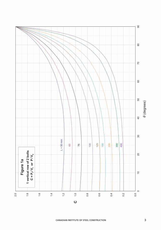
The charts below are intended to supplement the Handbook tables and provide values of C for one and two vertical rows of bolts and for load directions within 90o of the vertical. Resistances are given for values of the distance, L, defined as the horizontal distance between the bolt group centroid and the point of intersection of the horizontal line through the centroid and the line of application of the inclined load (See Figures).
Values of L range from 50 to 700 mm (depending on the bolt configuration), and are related to the eccentricity, e, according to the equation:
e = L cos
where is the angle between the load direction and the vertical.
Resistances have been calculated using the instantaneous centre of rotation method (Crawford and Kulak, 1971) for bearing-type joints with A325 bolts. Although the coefficients C may vary slightly for connections involving A490 bolts, it has become the practice to provide only one set of values for bolt groups consisting of A325 or A490 bolts (Kulak et al., 1987). The values of C provided herein correspond to the ultimate strength of bearing-type bolted joints, although they may be conservatively used for slip-critical joints:
P = C Vs
where Vs is the slip resistance of a single bolt according to Clause 13.12.2.2.
Other aspects of the design of bolted joints, such as the resistance of the bolted parts, are beyond the scope of SDS-2. Charts have been chosen over tables because the curves are concave up. Since tables can only cover a finite set of discrete angles, linear interpolation of C-values for angles other than those tabulated always errs on the unconservative side and, in some cases, interpolated values are grossly unconservative.
CANADIAN INSTITUTE OF STEEL CONSTRUCTION 1
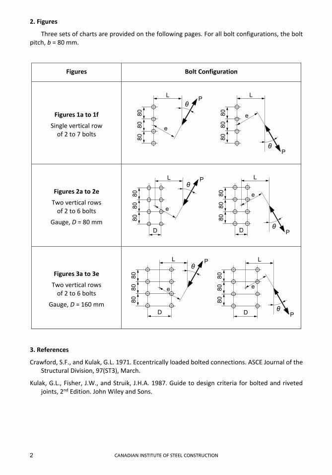
2. Figures
Three sets of charts are provided on the following pages. For all bolt configurations, the bolt pitch, b = 80 mm.
Figures Bolt Configuration
Figures 1a to 1f
Single vertical row of 2 to 7 bolts
Figures 2a to 2e
Two vertical rows of 2 to 6 bolts
Gauge, D = 80 mm
Figures 3a to 3e
Two vertical rows of 2 to 6 bolts
Gauge, D = 160 mm
3. References
Crawford, S.F., and Kulak, G.L. 1971. Eccentrically loaded bolted connections. ASCE Journal of the Structural Division, 97(ST3), March.
Kulak, G.L., Fisher, J.W., and Struik, J.H.A. 1987. Guide to design criteria for bolted and riveted joints, 2nd Edition. John Wiley and Sons.
8080
80
L
e
Pθ
8080
80
L
e
θP
e
PL
8080
80
D
θL
8080
80D
e
θP
L
8080
80
D
e
θP
L
8080
80
D
e
Pθ
CANADIAN INSTITUTE OF STEEL CONSTRUCTION2
0.0
0.2
0.4
0.6
0.8
1.0
1.2
1.4
1.6
1.8
2.0
010
2030
4050
6070
8090
L =
50 m
m
C
(deg
rees
)
60 75 100
150
200
300
400
125
Figu
re 1
a1
vert
ical
row
of 2
bol
tsC
= P
f /V r
or P
/Vs
3CANADIAN INSTITUTE OF STEEL CONSTRUCTION
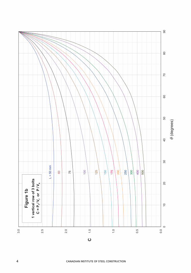
0.0
0.5
1.0
1.5
2.0
2.5
3.0
010
2030
4050
6070
8090
L =
50 m
m
C
(deg
rees
)
60 75 100
150
200
300
500
125
Figu
re 1
b1
vert
ical
row
of 3
bol
tsC
= P
f /V r
or P
/Vs
400
175
250
4 CANADIAN INSTITUTE OF STEEL CONSTRUCTION
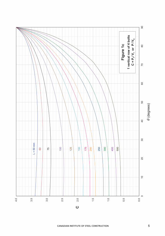
0.0
0.5
1.0
1.5
2.0
2.5
3.0
3.5
4.0
010
2030
4050
6070
8090
L =
50 m
m
C
(deg
rees
)
60 75 100
150
200
300
500
125
400
250
175
Figu
re 1
c1
vert
ical
row
of 4
bol
tsC
= P
f /V r
or P
/Vs
5CANADIAN INSTITUTE OF STEEL CONSTRUCTION
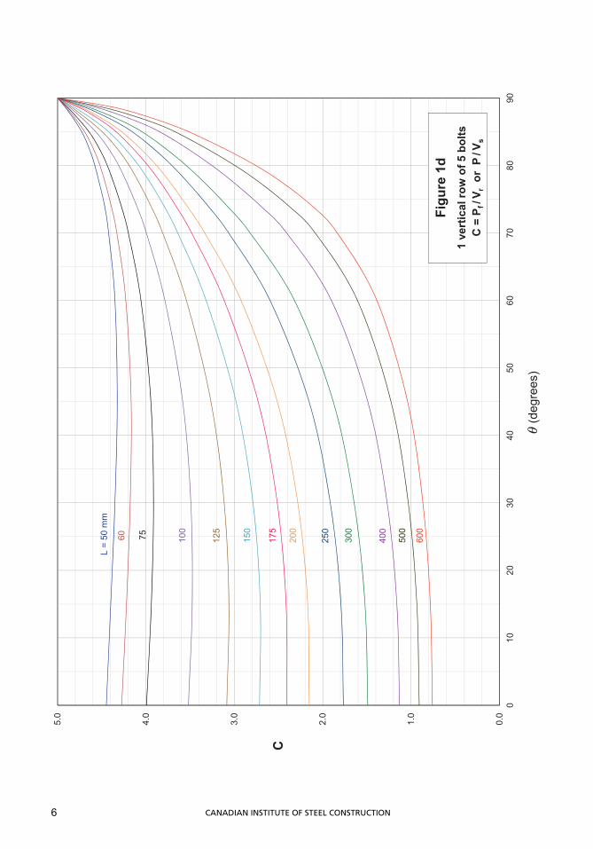
0.0
1.0
2.0
3.0
4.0
5.0
010
2030
4050
6070
8090
L =
50 m
m
C
(deg
rees
)
75 100
150
200
300
500
125
250
400
175
60
Figu
re 1
d1
vert
ical
row
of 5
bol
tsC
= P
f /V r
or P
/Vs
600
6 CANADIAN INSTITUTE OF STEEL CONSTRUCTION
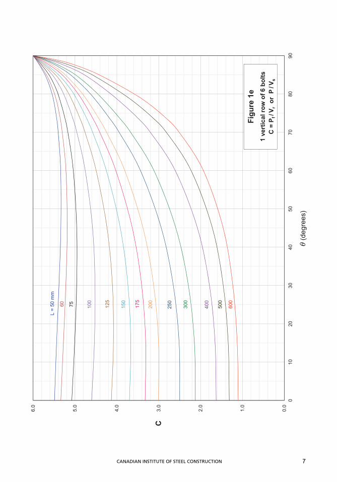
0.0
1.0
2.0
3.0
4.0
5.0
6.0
010
2030
4050
6070
8090
L =
50 m
m
C
(deg
rees
)
75 100
150
200
300
600
125
250
400
175
Figu
re 1
e1
vert
ical
row
of 6
bol
tsC
= P
f /V r
or P
/Vs
500
60
7CANADIAN INSTITUTE OF STEEL CONSTRUCTION
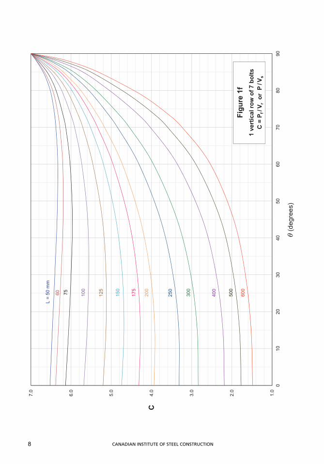
1.0
2.0
3.0
4.0
5.0
6.0
7.0
010
2030
4050
6070
8090
L =
50 m
m
C
(deg
rees
)
75 100
150
200
300
500
125
250
400
175
Figu
re 1
f1
vert
ical
row
of 7
bol
tsC
= P
f /V r
or P
/Vs
600
60
8 CANADIAN INSTITUTE OF STEEL CONSTRUCTION
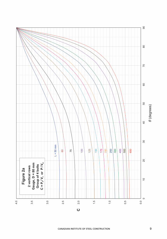
0.0
0.5
1.0
1.5
2.0
2.5
3.0
3.5
4.0
010
2030
4050
6070
8090
L =
50 m
m
C
(deg
rees
)
60 75 100
150
200
300
500
125
400
Figu
re 2
a2
vert
ical
row
sG
auge
, D =
80
mm
Gro
up o
f 4 b
olts
C =
Pf /
V ror
P/V
s
600
250
175
9CANADIAN INSTITUTE OF STEEL CONSTRUCTION
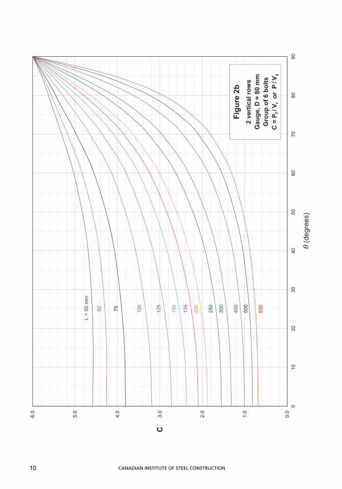
0.0
1.0
2.0
3.0
4.0
5.0
6.0
010
2030
4050
6070
8090
L =
50 m
m
C
(deg
rees
)
60 75 100
150
200
300
500
125
400
250
175
Figu
re 2
b2
vert
ical
row
sG
auge
, D =
80
mm
Gro
up o
f 6 b
olts
C =
Pf /
V ror
P/V
s
600
10 CANADIAN INSTITUTE OF STEEL CONSTRUCTION
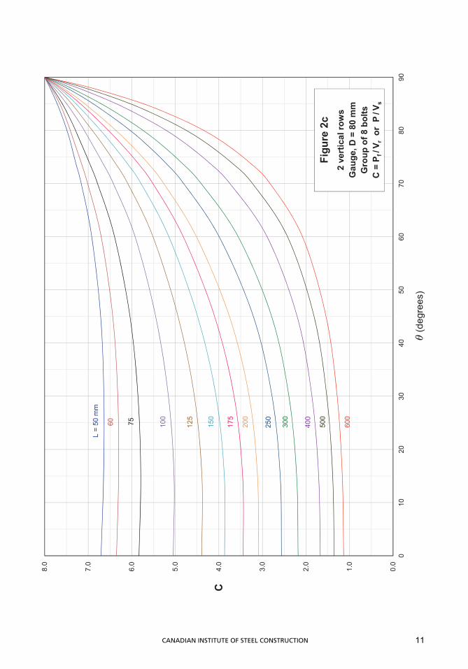
0.0
1.0
2.0
3.0
4.0
5.0
6.0
7.0
8.0
010
2030
4050
6070
8090
L =
50 m
m
C
(deg
rees
)
75 100
150
200
300
600
125
250
400
175
60
Figu
re 2
c2
vert
ical
row
sG
auge
, D =
80
mm
Gro
up o
f 8 b
olts
C =
Pf /
V ror
P/V
s
500
11CANADIAN INSTITUTE OF STEEL CONSTRUCTION
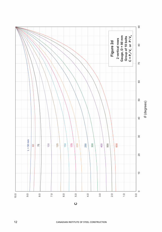
0.0
1.0
2.0
3.0
4.0
5.0
6.0
7.0
8.0
9.0
10.0
010
2030
4050
6070
8090
L =
50 m
m
C
(deg
rees
)
75 100
150
200
300
600
125
250
400
175
60
Figu
re 2
d2
vert
ical
row
sG
auge
, D =
80
mm
Gro
up o
f 10
bolts
C =
Pf /
V ror
P/V
s
500
12 CANADIAN INSTITUTE OF STEEL CONSTRUCTION
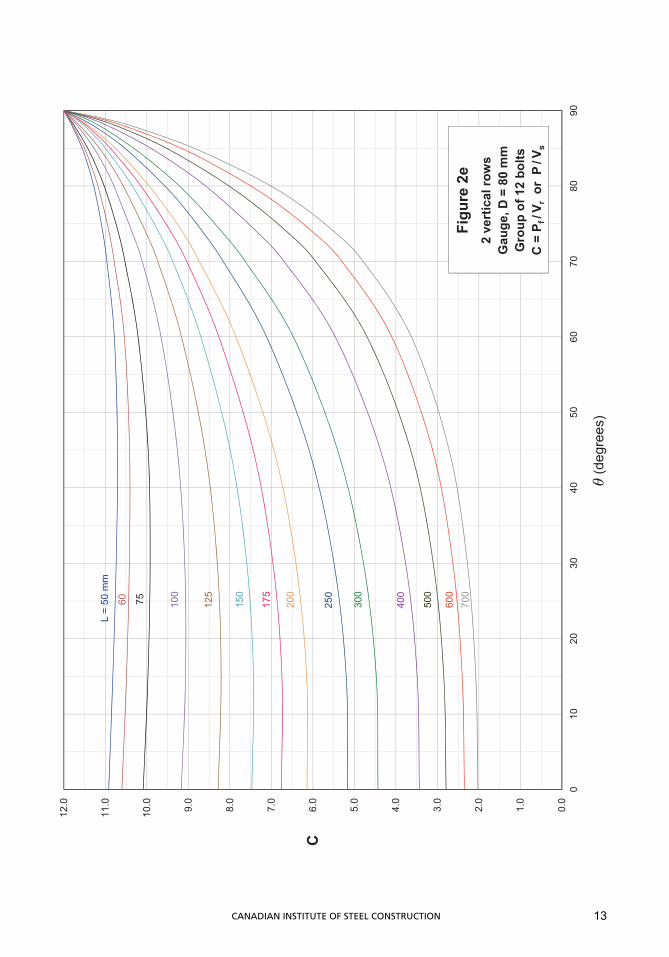
0.0
1.0
2.0
3.0
4.0
5.0
6.0
7.0
8.0
9.0
10.0
11.0
12.0
010
2030
4050
6070
8090
L =
50 m
m
C
(deg
rees
)
75 100
150
200
300
600
125
250
400
175
Figu
re 2
e2
vert
ical
row
sG
auge
, D =
80
mm
Gro
up o
f 12
bolts
C =
Pf /
V ror
P/V
s
500
700
60
13CANADIAN INSTITUTE OF STEEL CONSTRUCTION
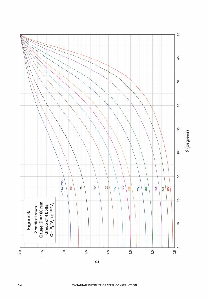
0.5
1.0
1.5
2.0
2.5
3.0
3.5
4.0
010
2030
4050
6070
8090
L =
50 m
m
C
(deg
rees
)
60 75 100
150
200
300
600
125
400
250
Figu
re 3
a2
vert
ical
row
sG
auge
, D =
160
mm
Gro
up o
f 4 b
olts
C =
Pf /
V ror
P/V
s
175
500
14 CANADIAN INSTITUTE OF STEEL CONSTRUCTION
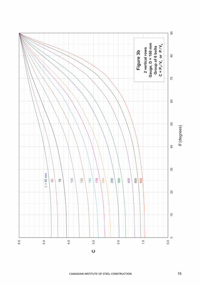
0.0
1.0
2.0
3.0
4.0
5.0
6.0
010
2030
4050
6070
8090
L =
50 m
m
C
(deg
rees
)
60 75 100
150
200
300
600
125
400
250
175
Figu
re 3
b2
vert
ical
row
sG
auge
, D =
160
mm
Gro
up o
f 6 b
olts
C =
Pf /
V ror
P/V
s
500
15CANADIAN INSTITUTE OF STEEL CONSTRUCTION
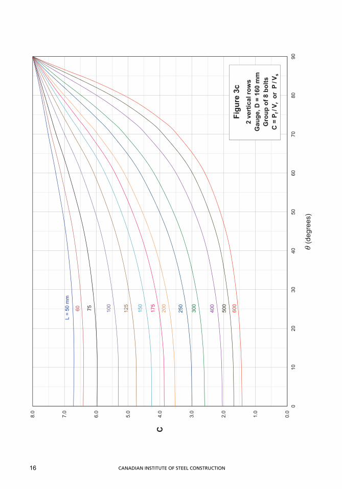
0.0
1.0
2.0
3.0
4.0
5.0
6.0
7.0
8.0
010
2030
4050
6070
8090
L =
50 m
m
C
(deg
rees
)
75 100
150
200
300
600
125
250
400
175
60
Figu
re 3
c2
vert
ical
row
sG
auge
, D =
160
mm
Gro
up o
f 8 b
olts
C =
Pf /
V ror
P/V
s
500
16 CANADIAN INSTITUTE OF STEEL CONSTRUCTION
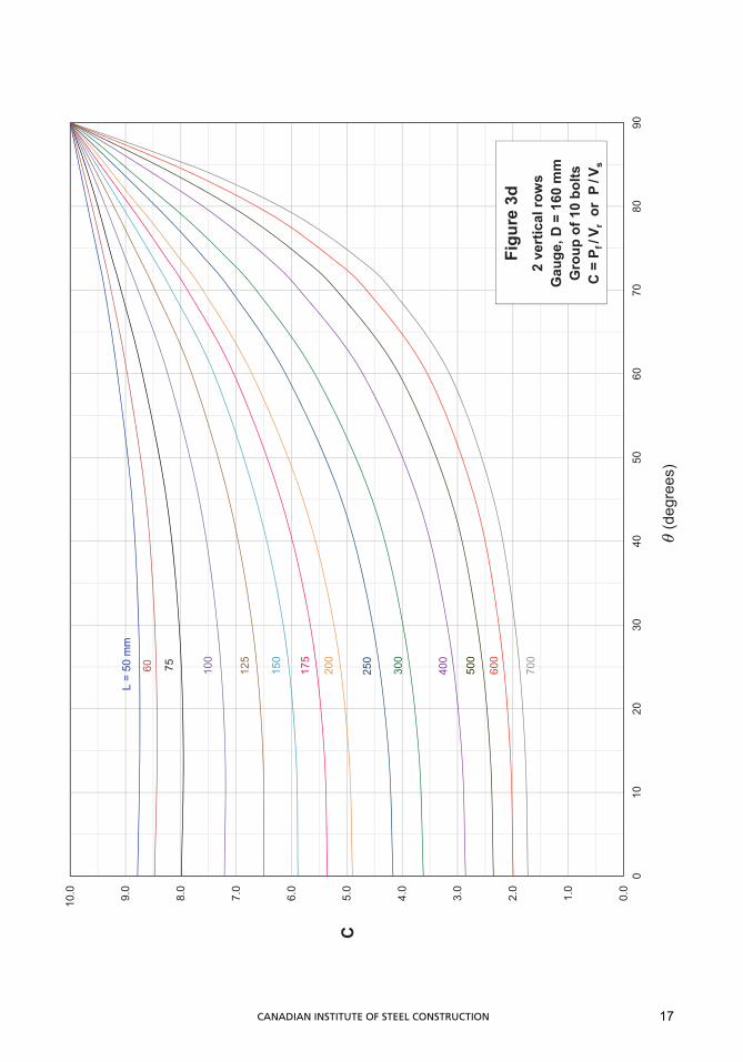
0.0
1.0
2.0
3.0
4.0
5.0
6.0
7.0
8.0
9.0
10.0
010
2030
4050
6070
8090
L =
50 m
m
C
(deg
rees
)
75 100
150
200
300
600
125
250
400
175
60
Figu
re 3
d2
vert
ical
row
sG
auge
, D =
160
mm
Gro
up o
f 10
bolts
C =
Pf /
V ror
P/V
s
500
700
17CANADIAN INSTITUTE OF STEEL CONSTRUCTION
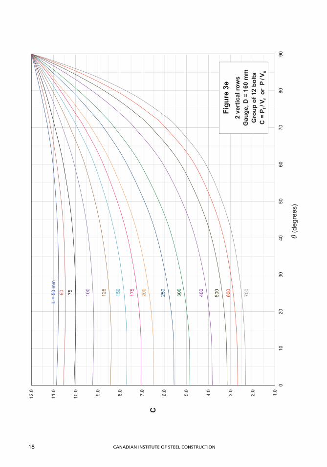
1.0
2.0
3.0
4.0
5.0
6.0
7.0
8.0
9.0
10.0
11.0
12.0
010
2030
4050
6070
8090
L =
50 m
m
C
(deg
rees
)
75 100
150
200
300
600
125
250
400
175
Figu
re 3
e2
vert
ical
row
sG
auge
, D =
160
mm
Gro
up o
f 12
bolts
C =
Pf /
V ror
P/V
s
500
700
60
18 CANADIAN INSTITUTE OF STEEL CONSTRUCTION