Circuit Elements in AC Circuits - Polytechnic Schoolfaculty.polytechnic.org/physics/2 HONORS PHYSICS...
30
CIRCUIT ELEMENTS IN AC CIRCUITS At this point, you’ve learned how resistors, capacitors and inductors act when in a DC circuit. It’s time to take a look at how they might act in an AC circuit. Specifically, we want to know what the net resistive nature (i.e., it’s tendency to resist current flow) is for each element. To make this quick and dirty, I’m going to put all the cogent information into a table. During class, I’ll zero in on the parts that really matter. 1.
-
Upload
phamnguyet -
Category
Documents
-
view
219 -
download
0
Transcript of Circuit Elements in AC Circuits - Polytechnic Schoolfaculty.polytechnic.org/physics/2 HONORS PHYSICS...
CIRCUIT ELEMENTS IN AC CIRCUITS
At this point, you’ve learned how resistors, capacitors and inductors act when in a DC circuit. It’s time to take a look at how they might act in an AC circuit. Specifically, we want to know what the net resistive nature (i.e., it’s tendency to resist current flow) is for each element.
To make this quick and dirty, I’m going to put all the cogent information into a table. During class, I’ll zero in on the parts that really matter.
1.
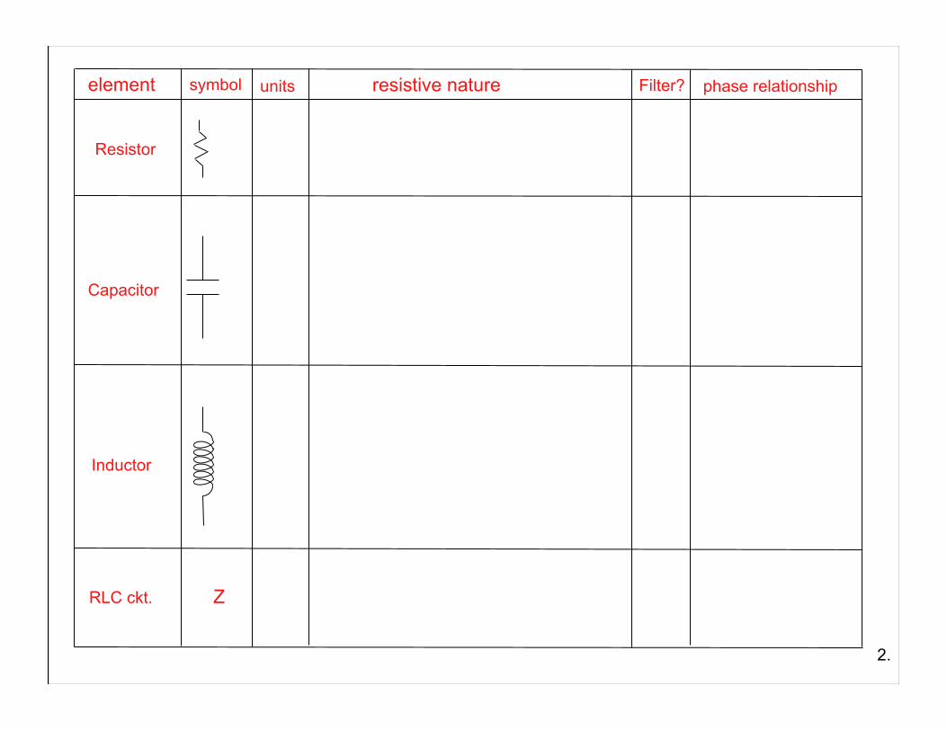
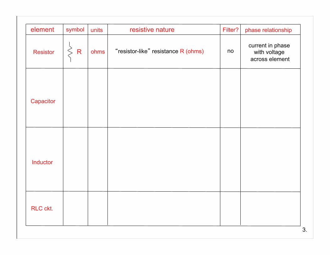
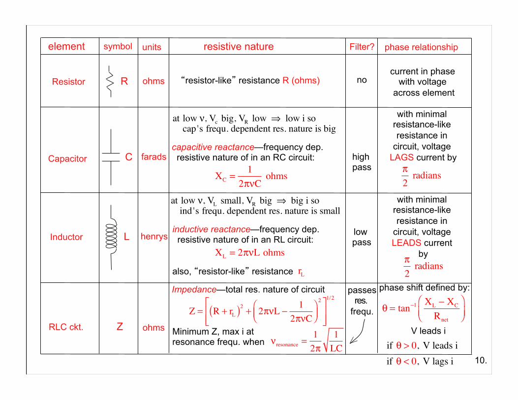
element symbol units resistive nature Filter? phase relationship
Resistor
Capacitor
Inductor
2.
RLC ckt. Z
element symbol units resistive nature Filter? phase relationship
R ohms Resistor
Capacitor
Inductor
“resistor-like” resistance R (ohms) no current in phase with voltage
across element
3.
RLC ckt.
element symbol units resistive nature Filter? phase relationship
R
C
ohms
farads
Resistor
Capacitor
Inductor
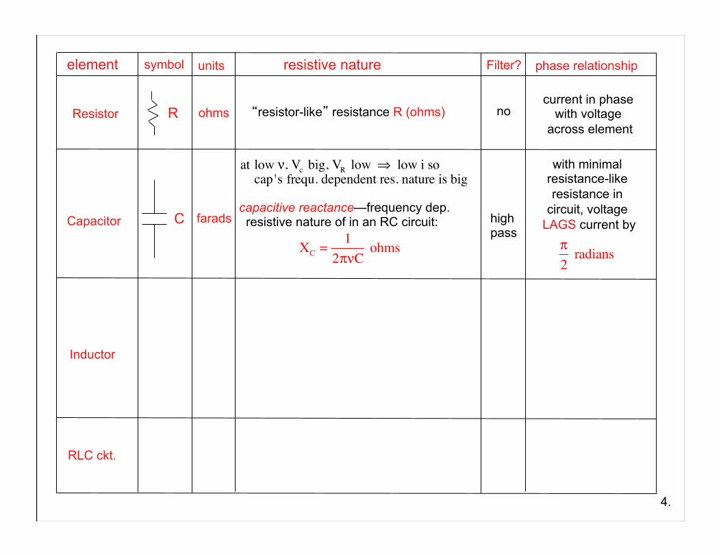
“resistor-like” resistance R (ohms)
capacitive reactance—frequency dep. resistive nature of in an RC circuit:
XC =1
2πνC ohms
no
high pass
current in phase with voltage
across element with minimal
resistance-like resistance in
circuit, voltage LAGS current by
π2
radians
4.
RLC ckt.
at low ν, Vc big, VR low ⇒ low i socap's frequ. dependent res. nature is big
RC circuit:
5.
V0
RC
VC VRiR
VCVRiR
RC
V0 sin 2πνt( )
RC
V0 sin 2πνt( )
VCVRiR
in DC circuit
in DC circuit
in AC circuit at low frequency
in AC circuit at high frequency
in AC circuit at high frequency
in AC circuit at high frequency
element symbol units resistive nature Filter? phase relationship
R
C
L
ohms
farads
henrys
Resistor
Capacitor
Inductor
“resistor-like” resistance R (ohms)
XL = 2πνL ohms
also, “resistor-like” resistance rL
no
high pass
low pass
current in phase with voltage
across element
π2
radians
π2
radians
6.
RLC ckt.
with minimal resistance-like resistance in
circuit, voltage LAGS current by
with minimal resistance-like resistance in
circuit, voltage LEADS current
by
capacitive reactance—frequency dep. resistive nature of in an RC circuit:
XC =1
2πνC ohms
at low ν, Vc big, VR low ⇒ low i socap's frequ. dependent res. nature is big
inductive reactance—frequency dep. resistive nature of in an RL circuit:
at low ν, VL small, VR big ⇒ big i soind 's frequ. dependent res. nature is small
RL circuit:
7.
V0
RL, rL
VL VRiR
VLVRiR
VLVRiR
in DC circuit
in DC circuit
in AC circuit at low frequency
in AC circuit at high frequency
in AC circuit at high frequency
in AC circuit at high frequency
R R
V0 sin 2πνt( )V0 sin 2πνt( )
L, rL L, rL
εinduced( )
element symbol units resistive nature Filter? phase relationship
R
C
L
ohms
farads
henrys
Resistor
Capacitor
Inductor
“resistor-like” resistance R (ohms) no
high pass
low pass
current in phase with voltage
across element
π2
radians
π2
radians
8.
RLC ckt.
impedance
Z ohms Z = R + rL( )2 + 2πνL −
12πνC
⎛⎝⎜
⎞⎠⎟2⎡
⎣⎢⎢
⎤
⎦⎥⎥
1/2
νresonance =12π
1LC
Minimum Z, max i at resonance frequ. when
passes res. frequ. θ = tan−1 XL − XC
Rnet
⎛⎝⎜
⎞⎠⎟
phase shift defined by:
V leads i if θ > 0, V leads i if θ < 0, V lags i
with minimal resistance-like resistance in
circuit, voltage LAGS current by
with minimal resistance-like resistance in
circuit, voltage LEADS current
by
capacitive reactance—frequency dep. resistive nature of in an RC circuit:
XC =1
2πνC ohms
at low ν, Vc big, VR low ⇒ low i socap's frequ. dependent res. nature is big
XL = 2πνL ohms
also, “resistor-like” resistance
inductive reactance—frequency dep. resistive nature of in an RL circuit:
at low ν, VL small, VR big ⇒ big i soind 's frequ. dependent res. nature is small
rL
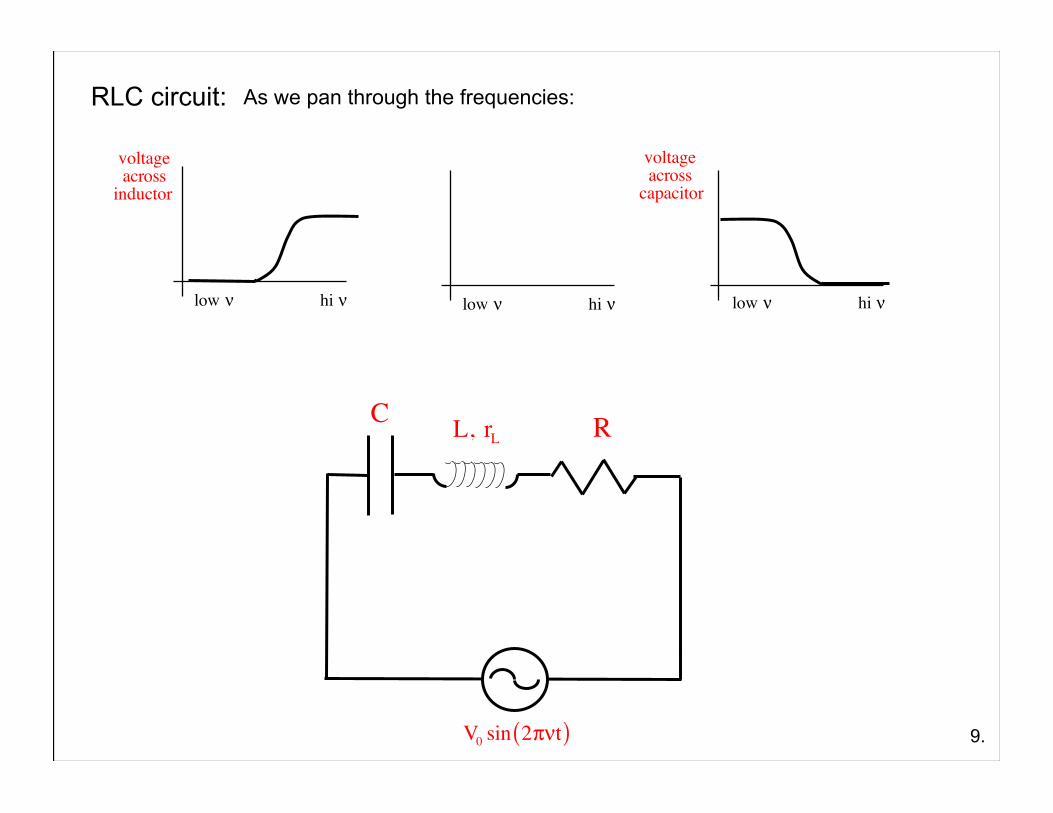
RLC circuit:
9.
As we pan through the frequencies:
R
V0 sin 2πνt( )
L, rLC
voltage acrossinductor
low ν hi ν low ν hi ν low ν hi ν
voltage acrosscapacitor
element symbol units resistive nature Filter? phase relationship
R
C
L
ohms
farads
henrys
Resistor
Capacitor
Inductor
“resistor-like” resistance R (ohms) no
high pass
low pass
current in phase with voltage
across element with minimal
resistance-like resistance in
circuit, voltage LAGS current by
π2
radians
with minimal resistance-like resistance in
circuit, voltage LEADS current
by π2
radians
10.
RLC ckt.
Impedance—total res. nature of circuit
Z ohms Z = R + rL( )2 + 2πνL −
12πνC
⎛⎝⎜
⎞⎠⎟2⎡
⎣⎢⎢
⎤
⎦⎥⎥
1/2
νresonance =12π
1LC
Minimum Z, max i at resonance frequ. when
passes res. frequ. θ = tan−1 XL − XC
Rnet
⎛⎝⎜
⎞⎠⎟
phase shift defined by:
V leads i if θ > 0, V leads i if θ < 0, V lags i
capacitive reactance—frequency dep. resistive nature of in an RC circuit:
XC =1
2πνC ohms
at low ν, Vc big, VR low ⇒ low i socap's frequ. dependent res. nature is big
XL = 2πνL ohms
also, “resistor-like” resistance
inductive reactance—frequency dep. resistive nature of in an RL circuit:
at low ν, VL small, VR big ⇒ big i soind 's frequ. dependent res. nature is small
rL
Summary of the Table
Resistors:
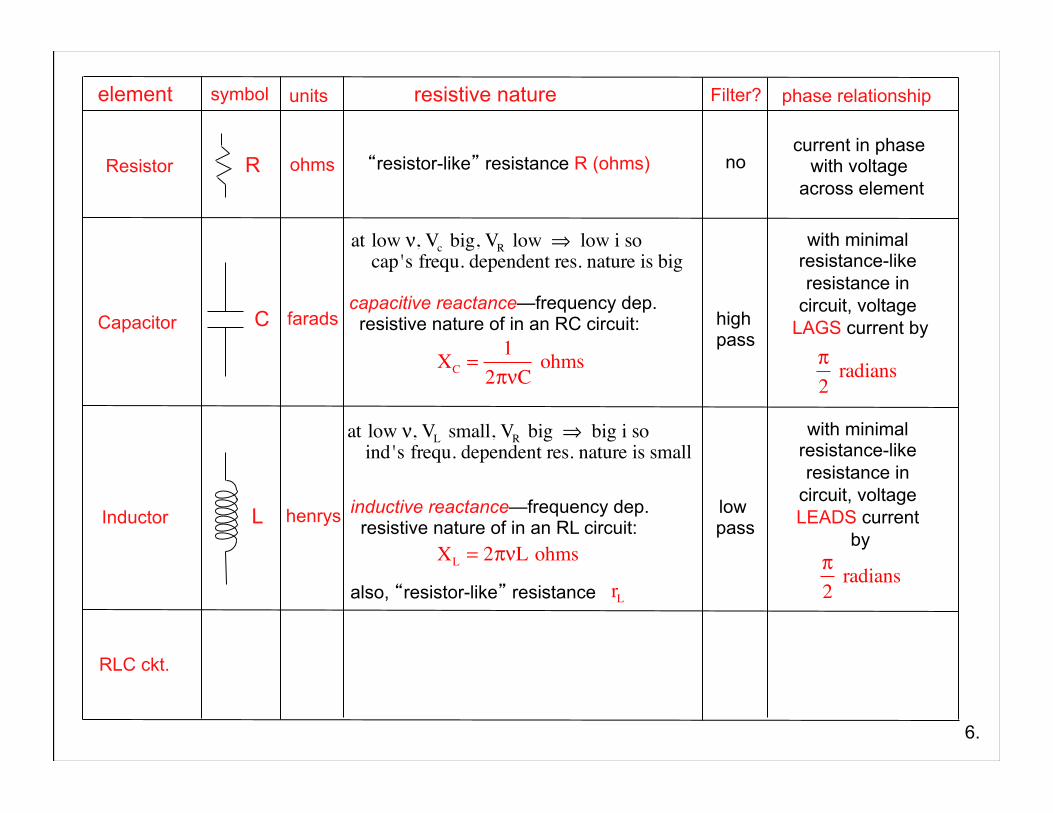
1.) Resistors have a resistive nature that is characterized as “resistance” and that has the units of ohms.
2.) The resistive nature (i.e., the resistance) of a resistor is not frequency dependent. That is, it doesn’t matter at what frequency the AC power supply is acting, the resistive nature of the resistor will always be the same.
3.) Because the resistive nature of the resistor is not frequency dependent, it doesn’t act as a frequency filter in any frequency range.
11.
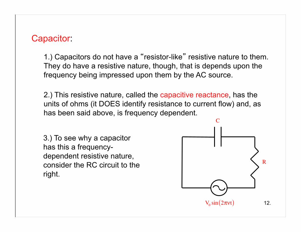
Capacitor:
1.) Capacitors do not have a “resistor-like” resistive nature to them. They do have a resistive nature, though, that is depends upon the frequency being impressed upon them by the AC source.
2.) This resistive nature, called the capacitive reactance, has the units of ohms (it DOES identify resistance to current flow) and, as has been said above, is frequency dependent.
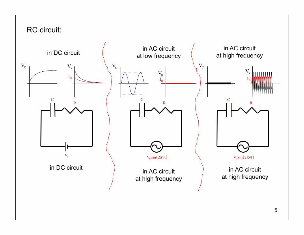
3.) To see why a capacitor has this a frequency-dependent resistive nature, consider the RC circuit to the right.
V0 sin 2πνt( )
R
C
12.
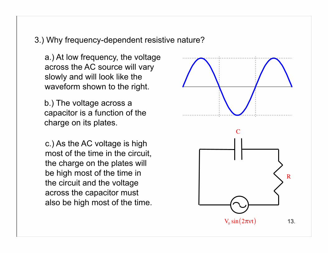
a.) At low frequency, the voltage across the AC source will vary slowly and will look like the waveform shown to the right.
3.) Why frequency-dependent resistive nature?
c.) As the AC voltage is high most of the time in the circuit, the charge on the plates will be high most of the time in the circuit and the voltage across the capacitor must also be high most of the time.
13.
b.) The voltage across a capacitor is a function of the charge on its plates.
V0 sin 2πνt( )
R
C
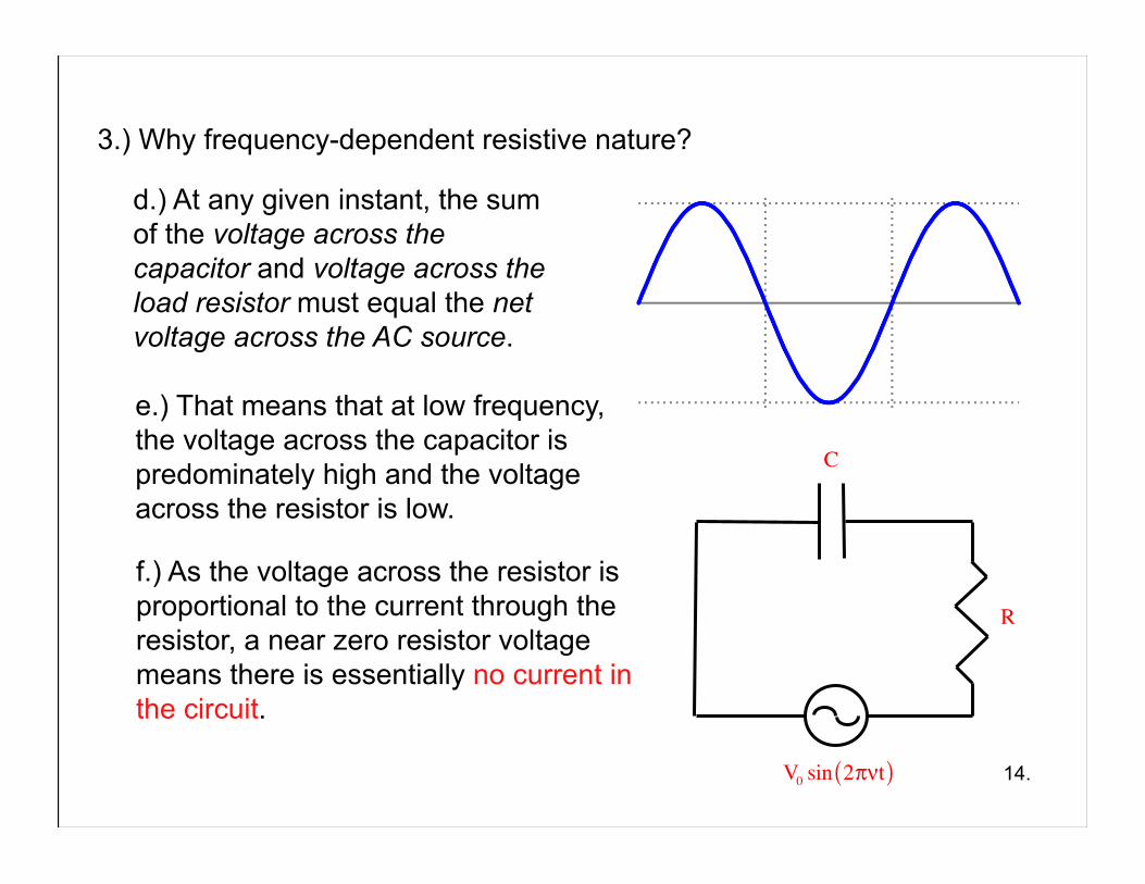
d.) At any given instant, the sum of the voltage across the capacitor and voltage across the load resistor must equal the net voltage across the AC source.
3.) Why frequency-dependent resistive nature?
14.
f.) As the voltage across the resistor is proportional to the current through the resistor, a near zero resistor voltage means there is essentially no current in the circuit.
e.) That means that at low frequency, the voltage across the capacitor is predominately high and the voltage across the resistor is low.
V0 sin 2πνt( )
R
C
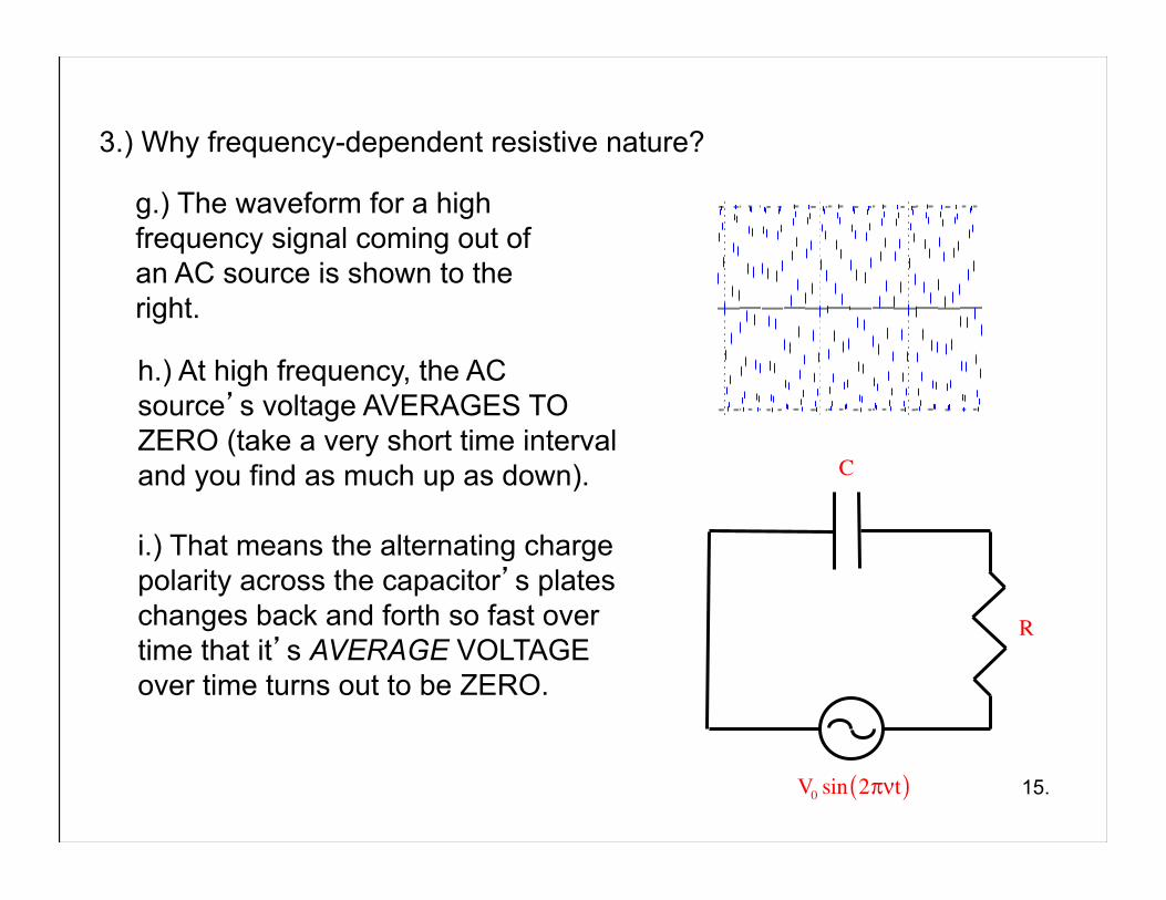
g.) The waveform for a high frequency signal coming out of an AC source is shown to the right.
3.) Why frequency-dependent resistive nature?
15.
h.) At high frequency, the AC source’s voltage AVERAGES TO ZERO (take a very short time interval and you find as much up as down).
i.) That means the alternating charge polarity across the capacitor’s plates changes back and forth so fast over time that it’s AVERAGE VOLTAGE over time turns out to be ZERO.
V0 sin 2πνt( )
R
C
3.) Why frequency-dependent resistive nature?
16.
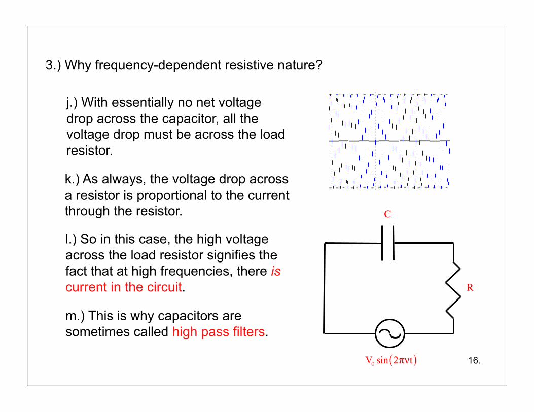
k.) As always, the voltage drop across a resistor is proportional to the current through the resistor.
j.) With essentially no net voltage drop across the capacitor, all the voltage drop must be across the load resistor.
l.) So in this case, the high voltage across the load resistor signifies the fact that at high frequencies, there is current in the circuit.
m.) This is why capacitors are sometimes called high pass filters.
V0 sin 2πνt( )
R
C
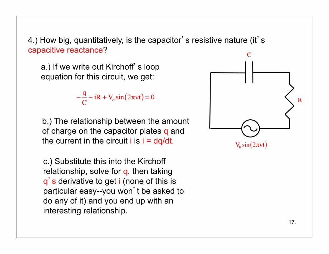
4.) How big, quantitatively, is the capacitor’s resistive nature (it’s capacitive reactance?
17.
c.) Substitute this into the Kirchoff relationship, solve for q, then taking q’s derivative to get i (none of this is particular easy--you won’t be asked to do any of it) and you end up with an interesting relationship.
a.) If we write out Kirchoff’s loop equation for this circuit, we get:
−qC− iR +Vo sin 2πνt( ) = 0
b.) The relationship between the amount of charge on the capacitor plates q and the current in the circuit i is i = dq/dt. V0 sin 2πνt( )
R
C
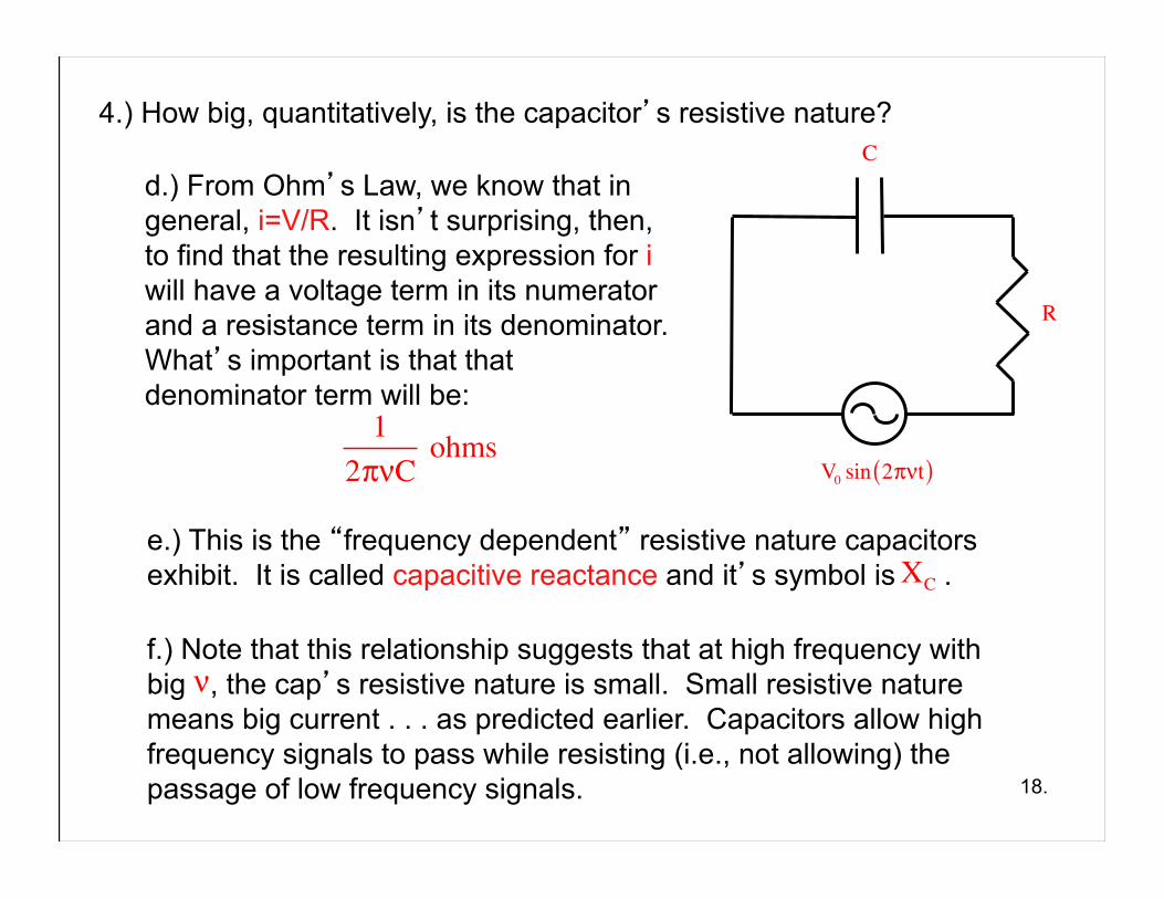
4.) How big, quantitatively, is the capacitor’s resistive nature?
18.
e.) This is the “frequency dependent” resistive nature capacitors exhibit. It is called capacitive reactance and it’s symbol is .
d.) From Ohm’s Law, we know that in general, i=V/R. It isn’t surprising, then, to find that the resulting expression for i will have a voltage term in its numerator and a resistance term in its denominator. What’s important is that that denominator term will be:
12πνC
ohms
f.) Note that this relationship suggests that at high frequency with big , the cap’s resistive nature is small. Small resistive nature means big current . . . as predicted earlier. Capacitors allow high frequency signals to pass while resisting (i.e., not allowing) the passage of low frequency signals.
ν
XC
V0 sin 2πνt( )
R
C
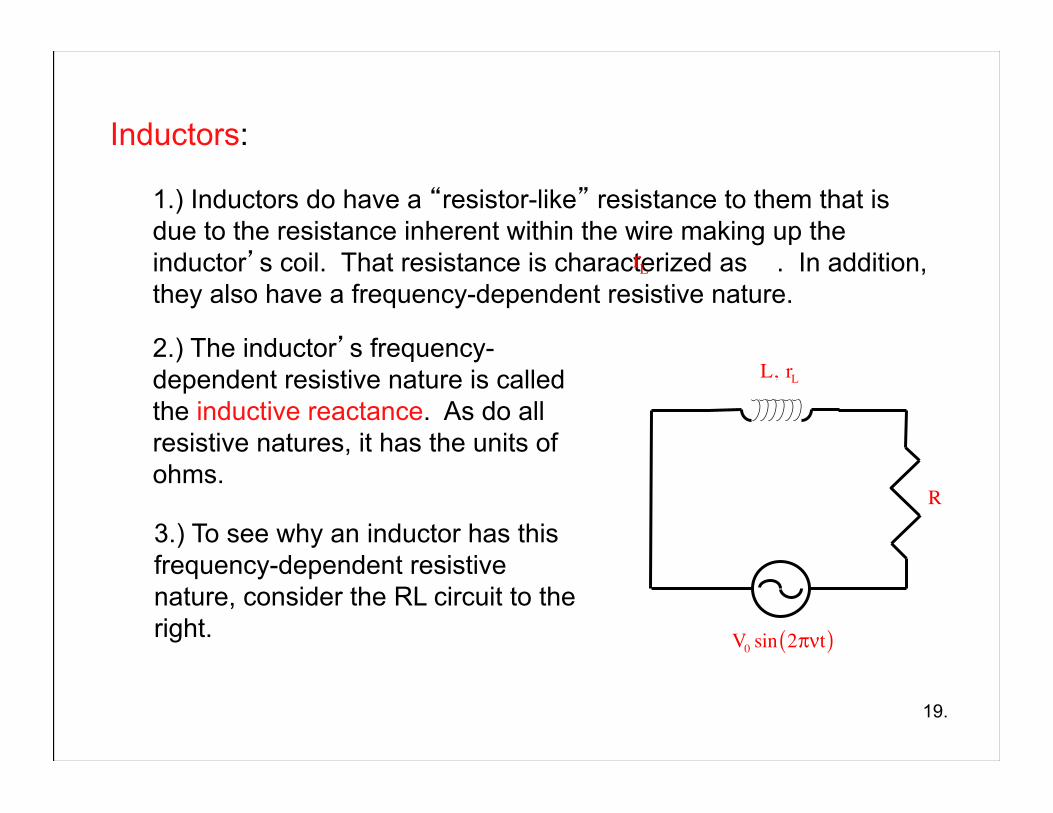
Inductors:
1.) Inductors do have a “resistor-like” resistance to them that is due to the resistance inherent within the wire making up the inductor’s coil. That resistance is characterized as . In addition, they also have a frequency-dependent resistive nature.
2.) The inductor’s frequency-dependent resistive nature is called the inductive reactance. As do all resistive natures, it has the units of ohms.
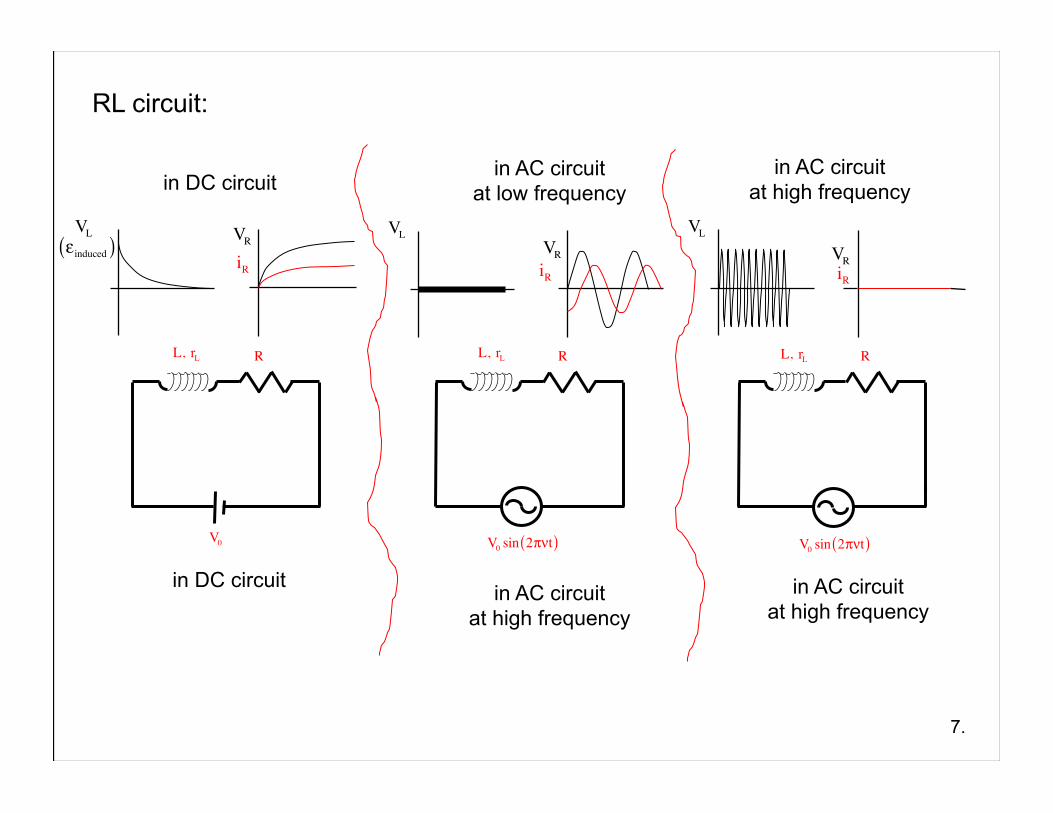
3.) To see why an inductor has this frequency-dependent resistive nature, consider the RL circuit to the right.
19.
L, rL
V0 sin 2πνt( )
R
rL
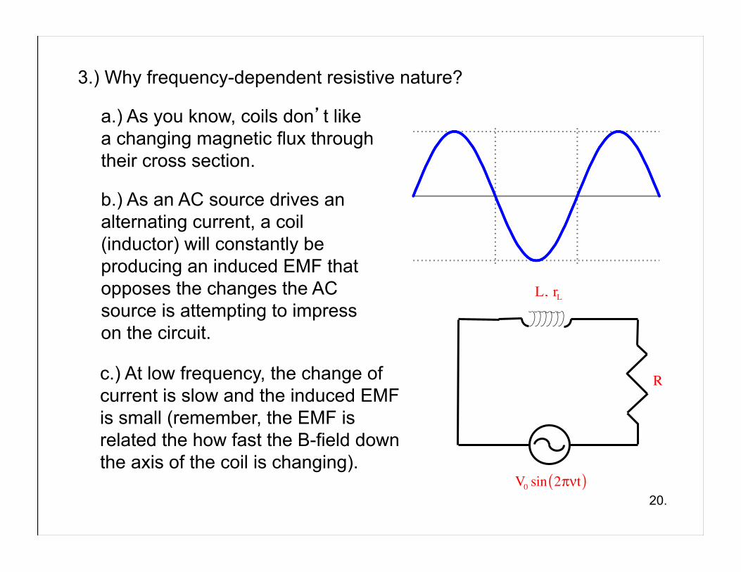
a.) As you know, coils don’t like a changing magnetic flux through their cross section.
3.) Why frequency-dependent resistive nature?
c.) At low frequency, the change of current is slow and the induced EMF is small (remember, the EMF is related the how fast the B-field down the axis of the coil is changing).
20.
b.) As an AC source drives an alternating current, a coil (inductor) will constantly be producing an induced EMF that opposes the changes the AC source is attempting to impress on the circuit.
L, rL
V0 sin 2πνt( )
R
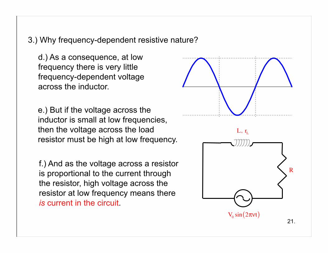
d.) As a consequence, at low frequency there is very little frequency-dependent voltage across the inductor.
3.) Why frequency-dependent resistive nature?
21.
f.) And as the voltage across a resistor is proportional to the current through the resistor, high voltage across the resistor at low frequency means there is current in the circuit.
e.) But if the voltage across the inductor is small at low frequencies, then the voltage across the load resistor must be high at low frequency.
L, rL
V0 sin 2πνt( )
R
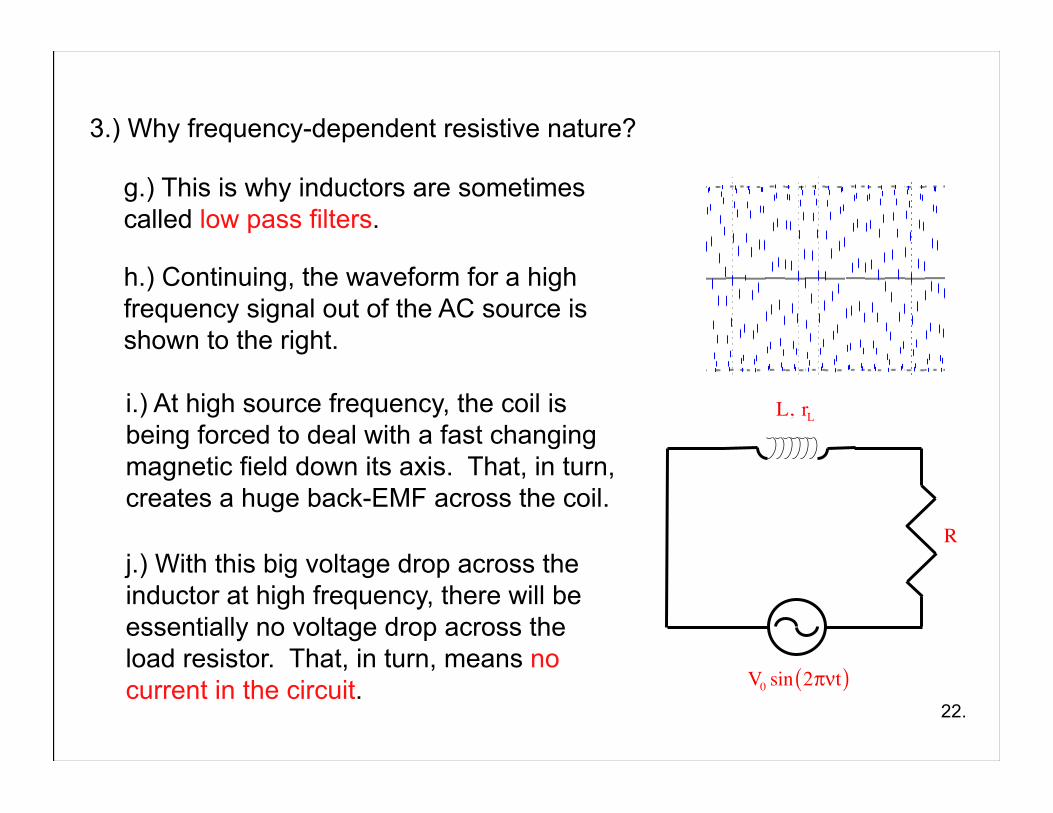
h.) Continuing, the waveform for a high frequency signal out of the AC source is shown to the right.
3.) Why frequency-dependent resistive nature?
22.
i.) At high source frequency, the coil is being forced to deal with a fast changing magnetic field down its axis. That, in turn, creates a huge back-EMF across the coil.
j.) With this big voltage drop across the inductor at high frequency, there will be essentially no voltage drop across the load resistor. That, in turn, means no current in the circuit.
g.) This is why inductors are sometimes called low pass filters.
L, rL
V0 sin 2πνt( )
R
4.) How big, quantitatively, is the inductor’s resistive nature?
23.
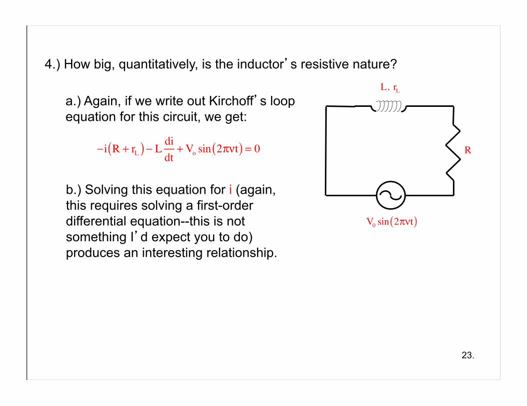
b.) Solving this equation for i (again, this requires solving a first-order differential equation--this is not something I’d expect you to do) produces an interesting relationship.
a.) Again, if we write out Kirchoff’s loop equation for this circuit, we get:
−i R + rL( ) − L didt
+Vo sin 2πνt( ) = 0
L, rL
V0 sin 2πνt( )
R
4.) How big, quantitatively, is the capacitor’s resistive nature?
24.
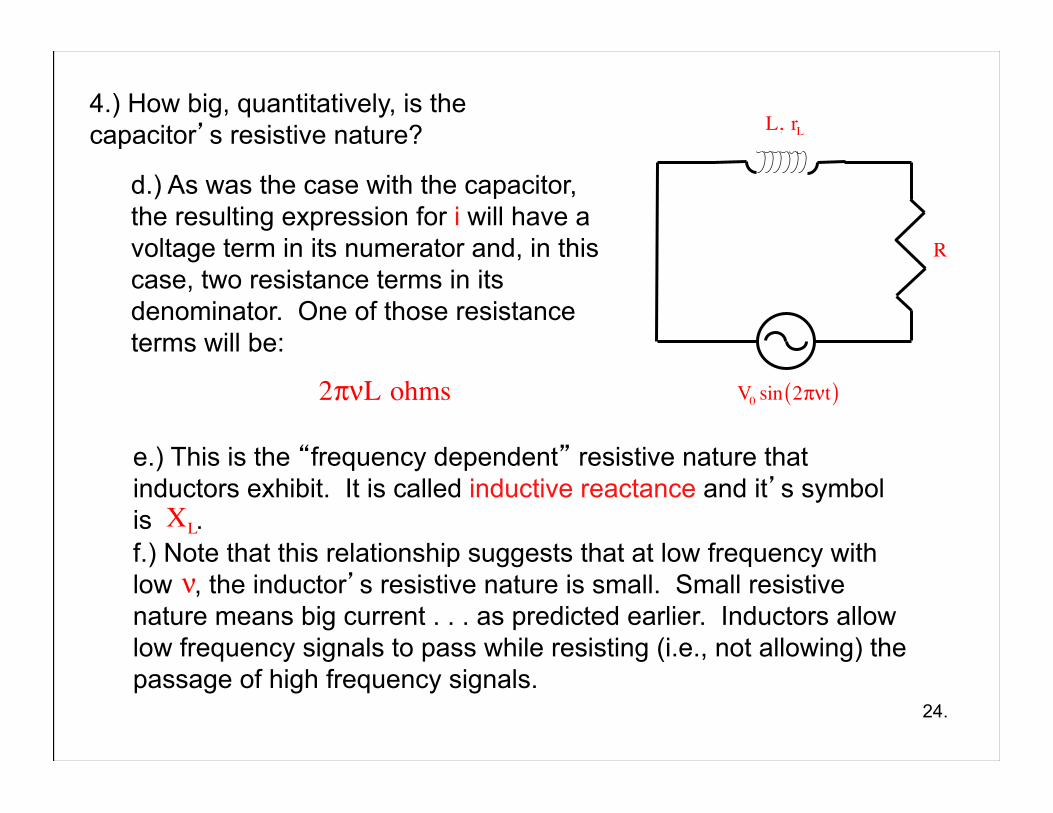
e.) This is the “frequency dependent” resistive nature that inductors exhibit. It is called inductive reactance and it’s symbol is .
d.) As was the case with the capacitor, the resulting expression for i will have a voltage term in its numerator and, in this case, two resistance terms in its denominator. One of those resistance terms will be:
2πνL ohms
ν
XL
L, rL
V0 sin 2πνt( )
R
f.) Note that this relationship suggests that at low frequency with low , the inductor’s resistive nature is small. Small resistive nature means big current . . . as predicted earlier. Inductors allow low frequency signals to pass while resisting (i.e., not allowing) the passage of high frequency signals.
RLC Circuits:
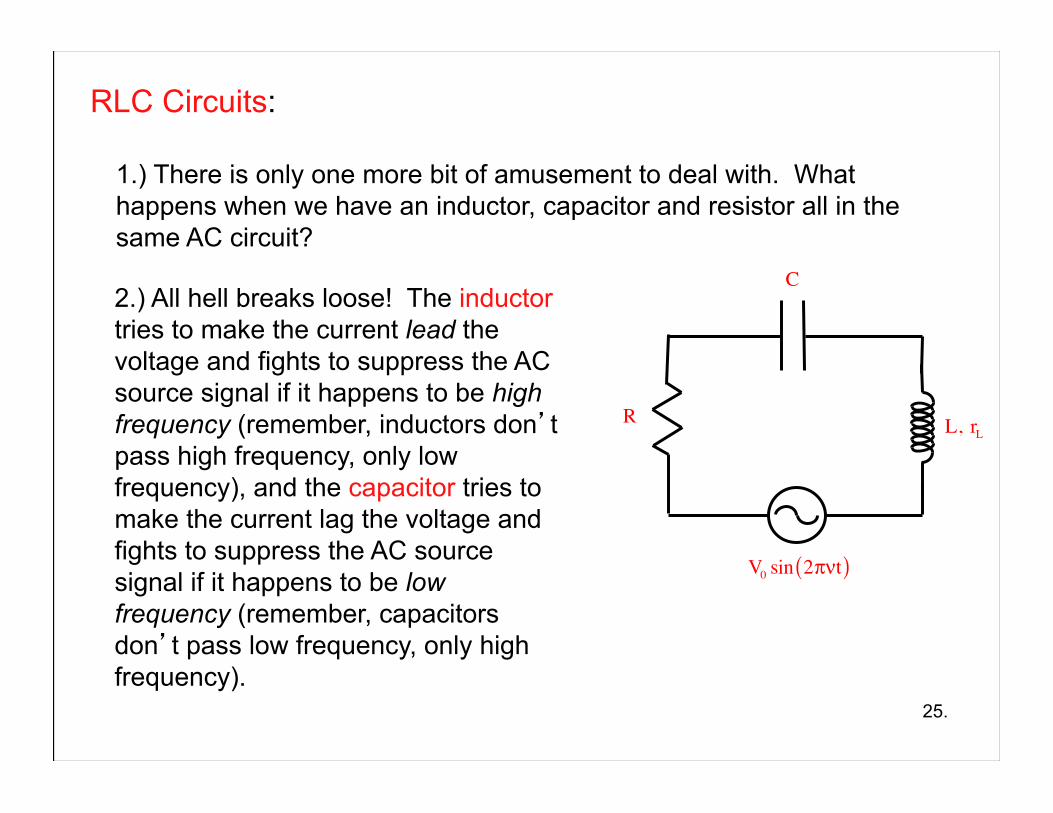
1.) There is only one more bit of amusement to deal with. What happens when we have an inductor, capacitor and resistor all in the same AC circuit?
2.) All hell breaks loose! The inductor tries to make the current lead the voltage and fights to suppress the AC source signal if it happens to be high frequency (remember, inductors don’t pass high frequency, only low frequency), and the capacitor tries to make the current lag the voltage and fights to suppress the AC source signal if it happens to be low frequency (remember, capacitors don’t pass low frequency, only high frequency).
25.
V0 sin 2πνt( )
L, rL
C
R
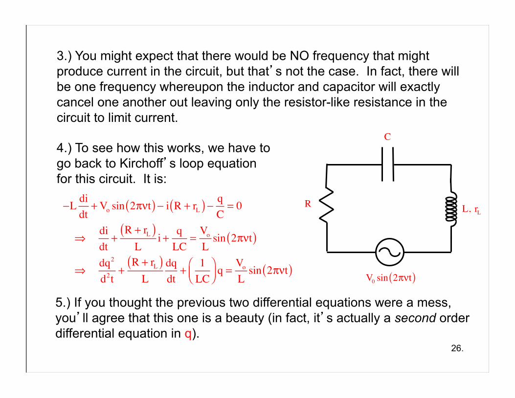
3.) You might expect that there would be NO frequency that might produce current in the circuit, but that’s not the case. In fact, there will be one frequency whereupon the inductor and capacitor will exactly cancel one another out leaving only the resistor-like resistance in the circuit to limit current.
4.) To see how this works, we have to go back to Kirchoff’s loop equation for this circuit. It is:
26.
V0 sin 2πνt( )
L, rL
C
R−L didt
+ Vo sin 2πνt( ) − i R + rL( ) − qC= 0
⇒ didt
+R + rL( )
Li + q
LC=
Vo
Lsin 2πνt( )
⇒ dq2
d2t+
R + rL( )L
dqdt
+1
LC⎛⎝⎜
⎞⎠⎟
q =Vo
Lsin 2πνt( )
5.) If you thought the previous two differential equations were a mess, you’ll agree that this one is a beauty (in fact, it’s actually a second order differential equation in q).
27.
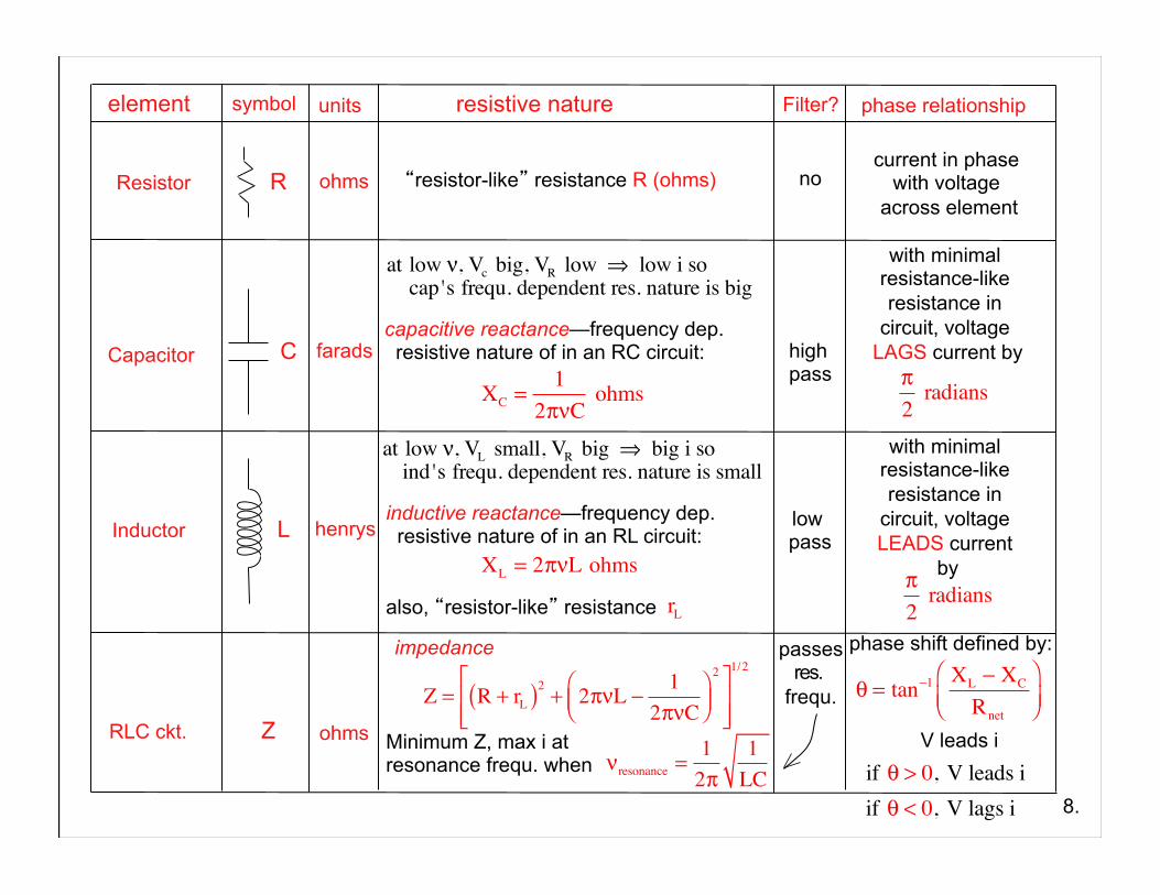
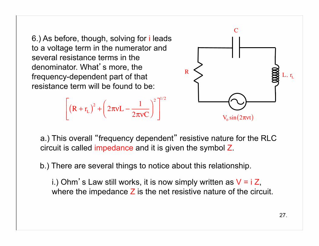
a.) This overall “frequency dependent” resistive nature for the RLC circuit is called impedance and it is given the symbol Z.
6.) As before, though, solving for i leads to a voltage term in the numerator and several resistance terms in the denominator. What’s more, the frequency-dependent part of that resistance term will be found to be:
R + rL( )2 + 2πνL −1
2πνC⎛⎝⎜
⎞⎠⎟2⎡
⎣⎢⎢
⎤
⎦⎥⎥
1/2
V0 sin 2πνt( )
L, rL
C
R
b.) There are several things to notice about this relationship.
i.) Ohm’s Law still works, it is now simply written as V = i Z, where the impedance Z is the net resistive nature of the circuit.
28.
R + rL( )2 + 2πνL −1
2πνC⎛⎝⎜
⎞⎠⎟2⎡
⎣⎢⎢
⎤
⎦⎥⎥
1/2
V0 sin 2πνt( )
L, rL
C
R
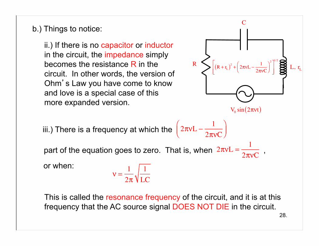
b.) Things to notice:
ii.) If there is no capacitor or inductor in the circuit, the impedance simply becomes the resistance R in the circuit. In other words, the version of Ohm’s Law you have come to know and love is a special case of this more expanded version.
iii.) There is a frequency at which the 2πνL −1
2πνC⎛⎝⎜
⎞⎠⎟
part of the equation goes to zero. That is, when , 2πνL =1
2πνCor when:
ν =12π
1LC
This is called the resonance frequency of the circuit, and it is at this frequency that the AC source signal DOES NOT DIE in the circuit.
29.
V0 sin 2πνt( )
L, rL
C
R
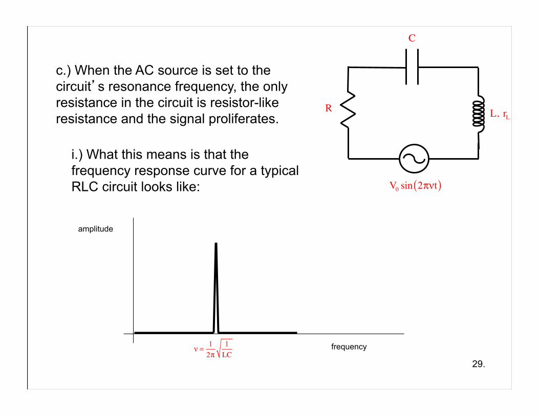
c.) When the AC source is set to the circuit’s resonance frequency, the only resistance in the circuit is resistor-like resistance and the signal proliferates.
i.) What this means is that the frequency response curve for a typical RLC circuit looks like:
frequency
amplitude
ν =12π
1LC
30.
V0 sin 2πνt( )
L, rL
C
R
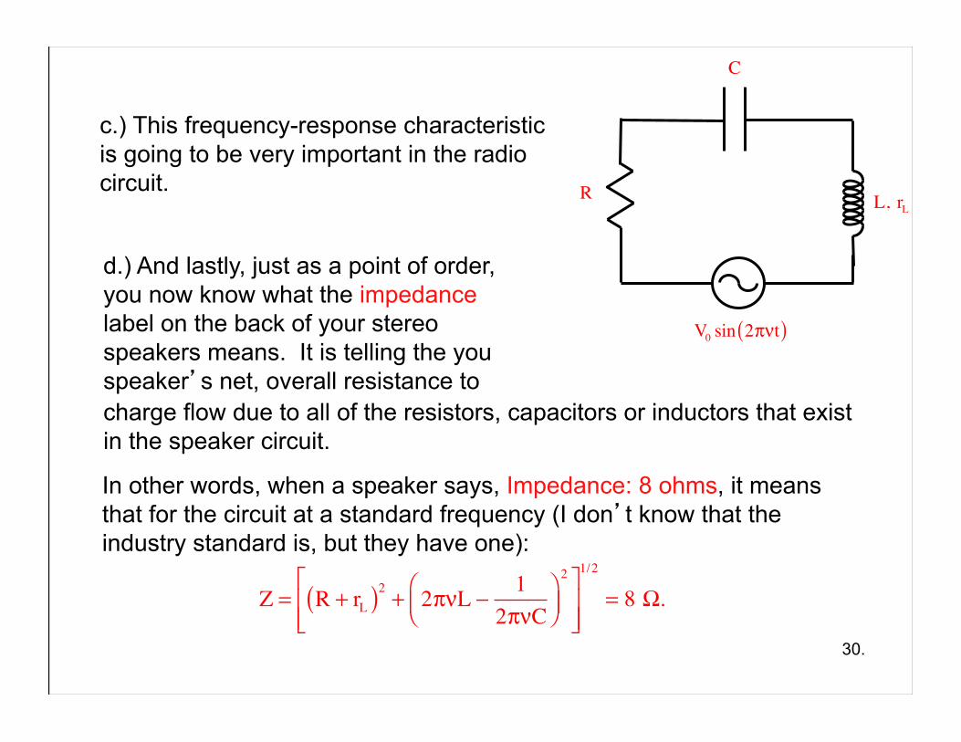
c.) This frequency-response characteristic is going to be very important in the radio circuit.
d.) And lastly, just as a point of order, you now know what the impedance label on the back of your stereo speakers means. It is telling the you speaker’s net, overall resistance to charge flow due to all of the resistors, capacitors or inductors that exist in the speaker circuit.
In other words, when a speaker says, Impedance: 8 ohms, it means that for the circuit at a standard frequency (I don’t know that the industry standard is, but they have one):
Z = R + rL( )2 + 2πνL −1
2πνC⎛⎝⎜
⎞⎠⎟
2⎡
⎣⎢⎢
⎤
⎦⎥⎥
1/2
= 8 Ω.