CIBANO 500 brochure - OMICRON
24
CIBANO 500 3-in-1 test system for medium- and high-voltage circuit breakers
Transcript of CIBANO 500 brochure - OMICRON
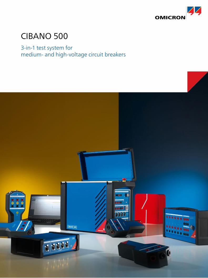
CIBANO 5003-in-1 test system for medium- and high-voltage circuit breakers
2
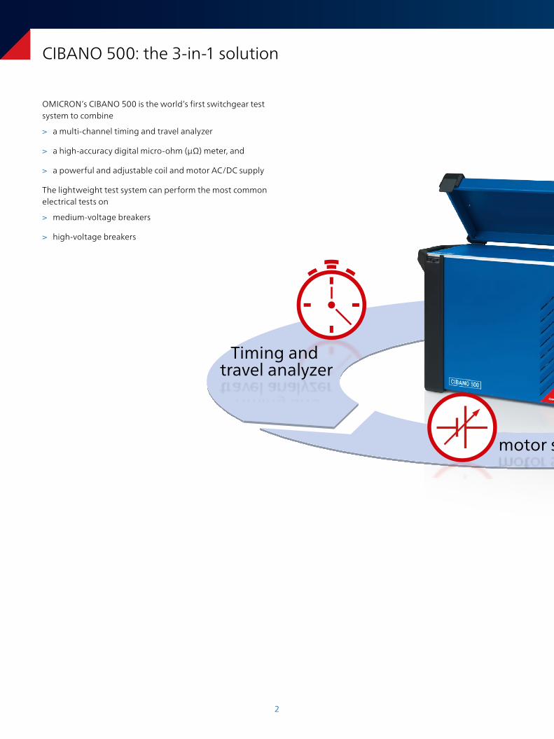
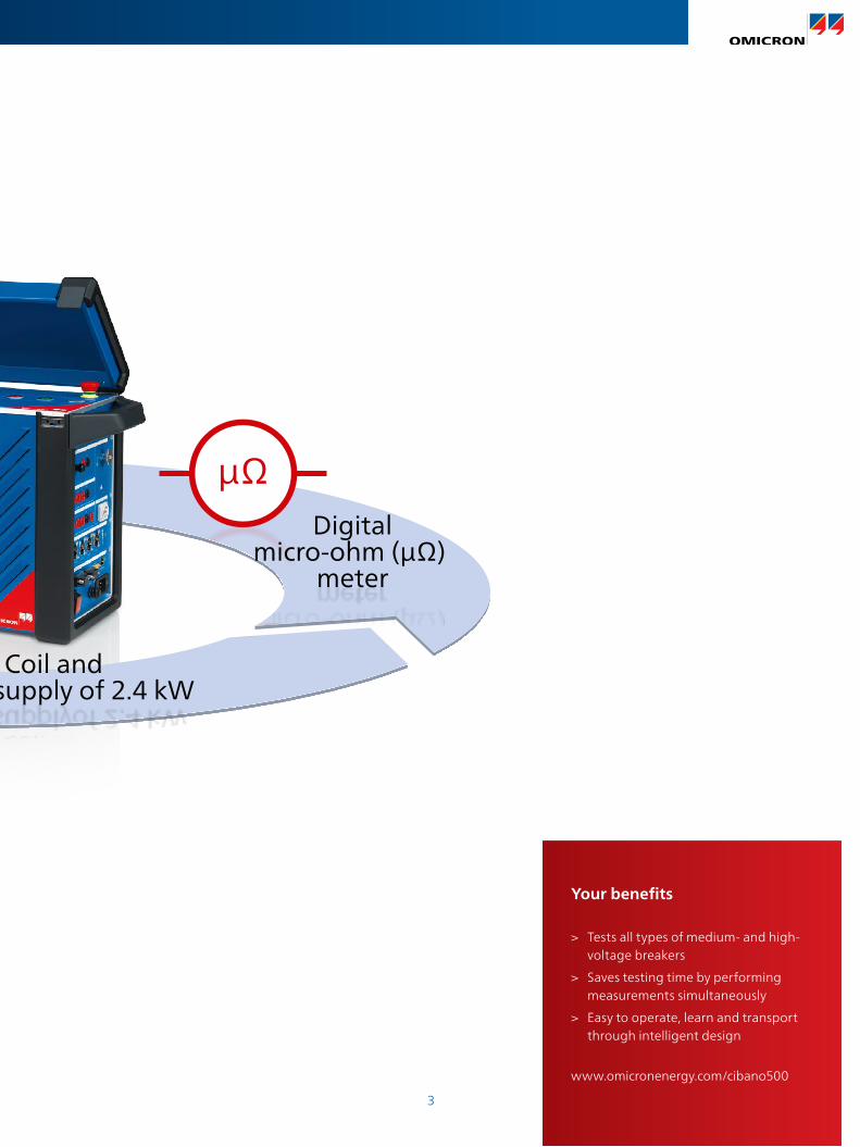
CIBANO 500: the 3-in-1 solution
µΩDigital
micro-ohm (µΩ) meter
Timing and travel analyzer
Coil and motor supply of 2.4 kW
OMICRON’s CIBANO 500 is the world’s first switchgear test system to combine
> a multi-channel timing and travel analyzer
> a high-accuracy digital micro-ohm (µΩ) meter, and
> a powerful and adjustable coil and motor AC/DC supply
The lightweight test system can perform the most common electrical tests on
> medium-voltage breakers
> high-voltage breakers
3
CIBANO 500: the 3-in-1 solution
µΩDigital
micro-ohm (µΩ) meter
Timing and travel analyzer
Coil and motor supply of 2.4 kW
Your benefits
> Tests all types of medium- and high-voltage breakers
> Saves testing time by performing measurements simultaneously
> Easy to operate, learn and transport through intelligent design
www.omicronenergy.com/cibano500
4
> +
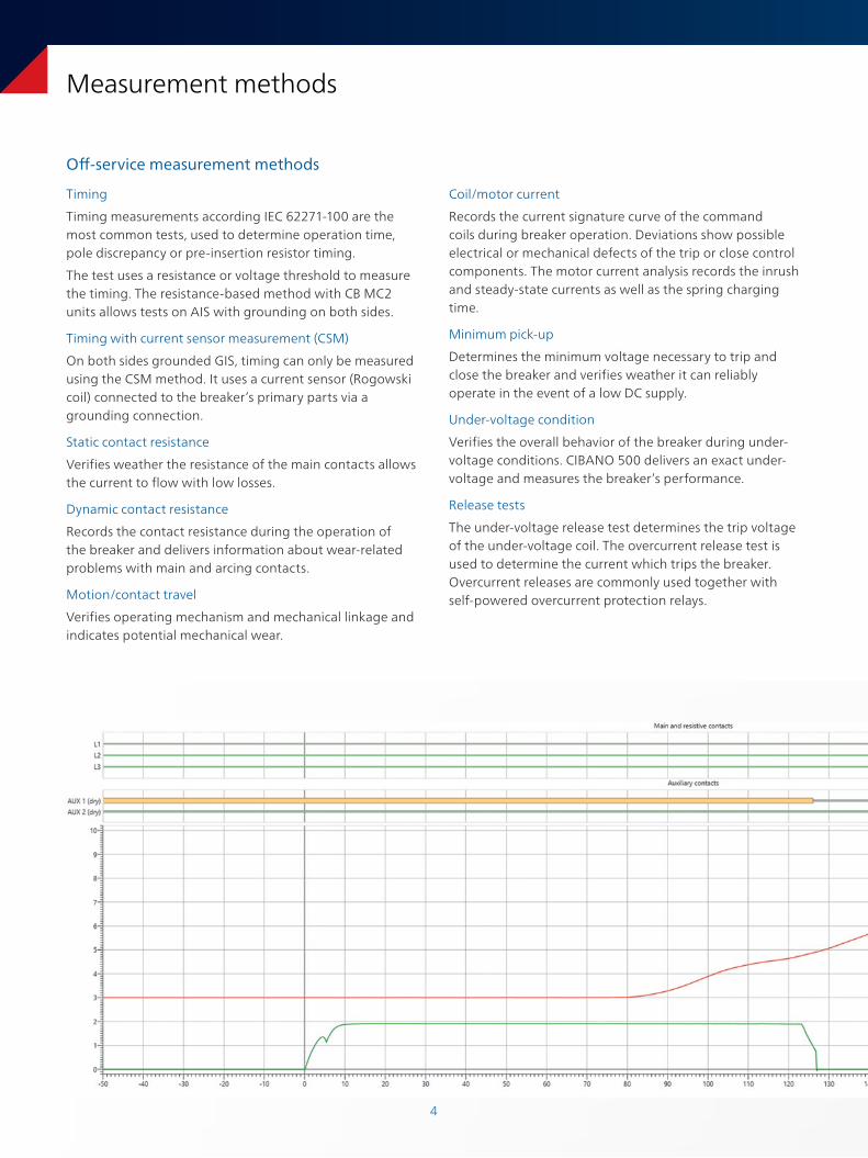
Measurement methods
Off-service measurement methods
Timing
Timing measurements according IEC 62271-100 are the most common tests, used to determine operation time, pole discrepancy or pre-insertion resistor timing.
The test uses a resistance or voltage threshold to measure the timing. The resistance-based method with CB MC2 units allows tests on AIS with grounding on both sides.
Timing with current sensor measurement (CSM)
On both sides grounded GIS, timing can only be measured using the CSM method. It uses a current sensor (Rogowski coil) connected to the breaker’s primary parts via a grounding connection.
Static contact resistance
Verifies weather the resistance of the main contacts allows the current to flow with low losses.
Dynamic contact resistance
Records the contact resistance during the operation of the breaker and delivers information about wear-related problems with main and arcing contacts.
Motion/contact travel
Verifies operating mechanism and mechanical linkage and indicates potential mechanical wear.
Coil/motor current
Records the current signature curve of the command coils during breaker operation. Deviations show possible electrical or mechanical defects of the trip or close control components. The motor current analysis records the inrush and steady-state currents as well as the spring charging time.
Minimum pick-up
Determines the minimum voltage necessary to trip and close the breaker and verifies weather it can reliably operate in the event of a low DC supply.
Under-voltage condition
Verifies the overall behavior of the breaker during under-voltage conditions. CIBANO 500 delivers an exact under-voltage and measures the breaker’s performance.
Release tests
The under-voltage release test determines the trip voltage of the under-voltage coil. The overcurrent release test is used to determine the current which trips the breaker. Overcurrent releases are commonly used together with self-powered overcurrent protection relays.
5
> +
Measurement methods
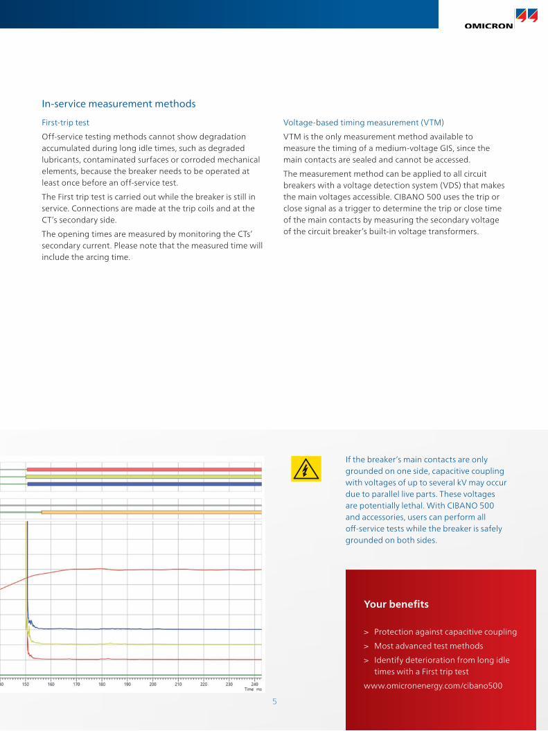
First-trip test
Off-service testing methods cannot show degradation accumulated during long idle times, such as degraded lubricants, contaminated surfaces or corroded mechanical elements, because the breaker needs to be operated at least once before an off-service test.
The First trip test is carried out while the breaker is still in service. Connections are made at the trip coils and at the CT’s secondary side.
The opening times are measured by monitoring the CTs’ secondary current. Please note that the measured time will include the arcing time.
In-service measurement methods
Voltage-based timing measurement (VTM)
VTM is the only measurement method available to measure the timing of a medium-voltage GIS, since the main contacts are sealed and cannot be accessed.
The measurement method can be applied to all circuit breakers with a voltage detection system (VDS) that makes the main voltages accessible. CIBANO 500 uses the trip or close signal as a trigger to determine the trip or close time of the main contacts by measuring the secondary voltage of the circuit breaker’s built-in voltage transformers.
Your benefits
> Protection against capacitive coupling
> Most advanced test methods
> Identify deterioration from long idle times with a First trip test
www.omicronenergy.com/cibano500
If the breaker’s main contacts are only grounded on one side, capacitive coupling with voltages of up to several kV may occur due to parallel live parts. These voltages are potentially lethal. With CIBANO 500 and accessories, users can perform all off-service tests while the breaker is safely grounded on both sides.
6
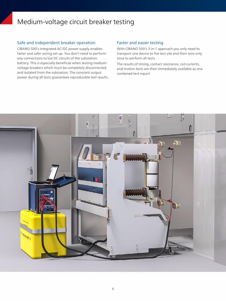
Medium-voltage circuit breaker testing
Safe and independent breaker operationCIBANO 500’s integrated AC/DC power supply enables faster and safer wiring set up. You don’t need to perform any connections to live DC circuits of the substation battery. This is especially beneficial when testing medium-voltage breakers which must be completely disconnected and isolated from the substation. The constant output power during all tests guarantees reproducible test results.
Faster and easier testingWith CIBANO 500’s 3-in-1 approach you only need to transport one device to the test site and then wire only once to perform all tests.
The results of timing, contact resistance, coil currents, and motion tests are then immediately available as one combined test report.
7
Common tests
> Timing
> Static contact resistance
> Coil current analysis
> Under-voltage condition
> Motion/contact travel
> Under-voltage release
> Overcurrent release
Your benefits
> Extensive selection of sophisticated test methods
> Integrated power supply (2.4 kW) for safe and independent testing
> Lightweight test system (20 kg / 44 lbs) for easy transportation to test site
www.omicronenergy.com/cibano500
Voltage-based timing measurement (VTM)
VTM allows in-service timing measurements on MV SF6 CBs. The tests are performed via the secondary contacts of a built-in inductive or capacitive VT.
Motion as timing trigger
CIBANO 500 can measure the mechanical operation time of a circuit breaker without close coil by using the point in time when the circuit breaker contact begins to move as the starting time for the measurement.
Under-voltage release test
Medium voltage circuit breakers are equipped with an under-voltage (UV) release if the related protection system has no supply voltage backup. The UV release test determines the trip voltage of the under-voltage coil.
Overcurrent release test
Overcurrent releases are used on circuit breakers in substations where self-powered overcurrent protection devices are used. The Overcurrent release test determines the current needed to trip the breaker.
8
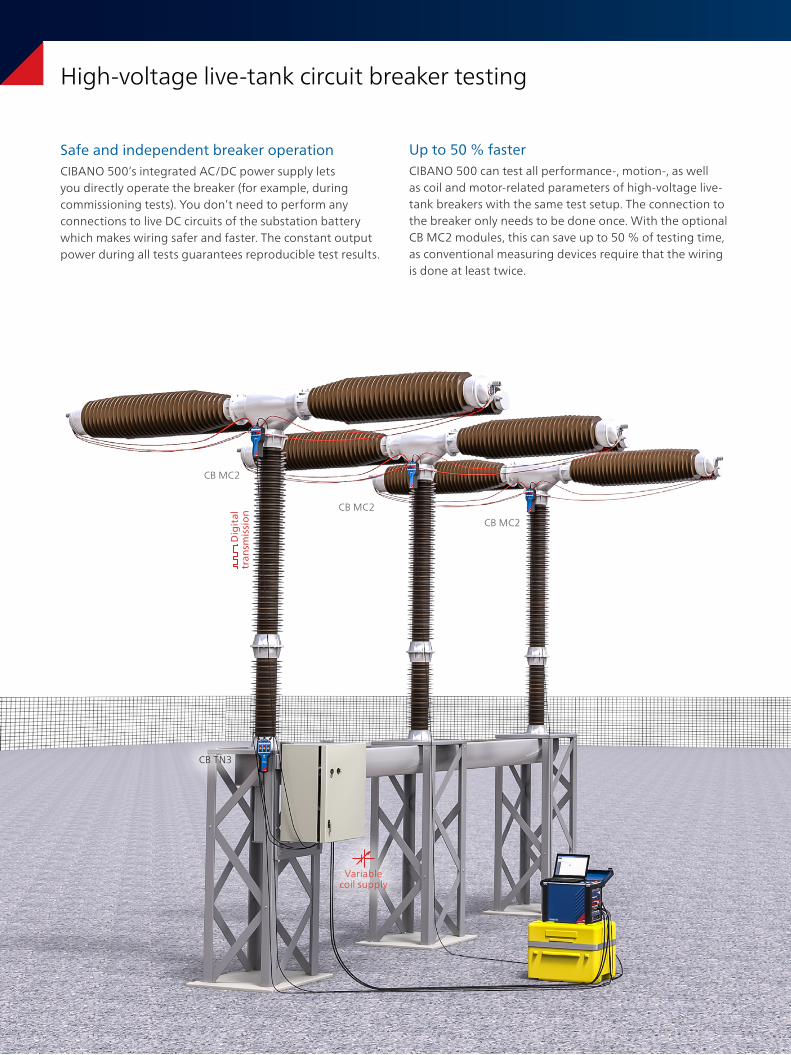
Up to 50 % fasterCIBANO 500 can test all performance-, motion-, as well as coil and motor-related parameters of high-voltage live-tank breakers with the same test setup. The connection to the breaker only needs to be done once. With the optional CB MC2 modules, this can save up to 50 % of testing time, as conventional measuring devices require that the wiring is done at least twice.
High-voltage live-tank circuit breaker testing
D
igit
al
tran
smis
sio
n CB MC2
CB MC2
CB MC2
Variable coil supply
Safe and independent breaker operationCIBANO 500’s integrated AC/DC power supply lets you directly operate the breaker (for example, during commissioning tests). You don’t need to perform any connections to live DC circuits of the substation battery which makes wiring safer and faster. The constant output power during all tests guarantees reproducible test results.
CB TN3
9
Measuring large breakers
By using EtherCAT®-communication, the number of measuring channels can be extended to any number needed by very large or specially designed circuit breakers (for example, large breakers with independent pole operation).
Synchronous timing measurement
During timing tests on high-voltage live-tank circuit breakers, CIBANO 500 synchronously assesses the timing of all main contacts, auxiliary contacts, and pre-insertion resistors. It measures the differences between the fastest and slowest phase and can detect incorrect mechanical adjustments or wear phenomena of the circuit breakers.
Both sides grounded
All of the tests on high-voltage breakers can be performed while the circuit breaker is grounded on both sides. This results in increased safety levels for operating personnel.
Common tests
> Timing
> Static contact resistance
> Dynamic contact resistance test
> Motion/contact travel
> Coil/motor current analysis
> Under-voltage condition
> Minimum pick-up
Your benefits
> Both sides grounded
> Up to 50 % shorter testing times
> Integrated power supply (2.4 kW) for safe and independent testing
www.omicronenergy.com/cibano500
10
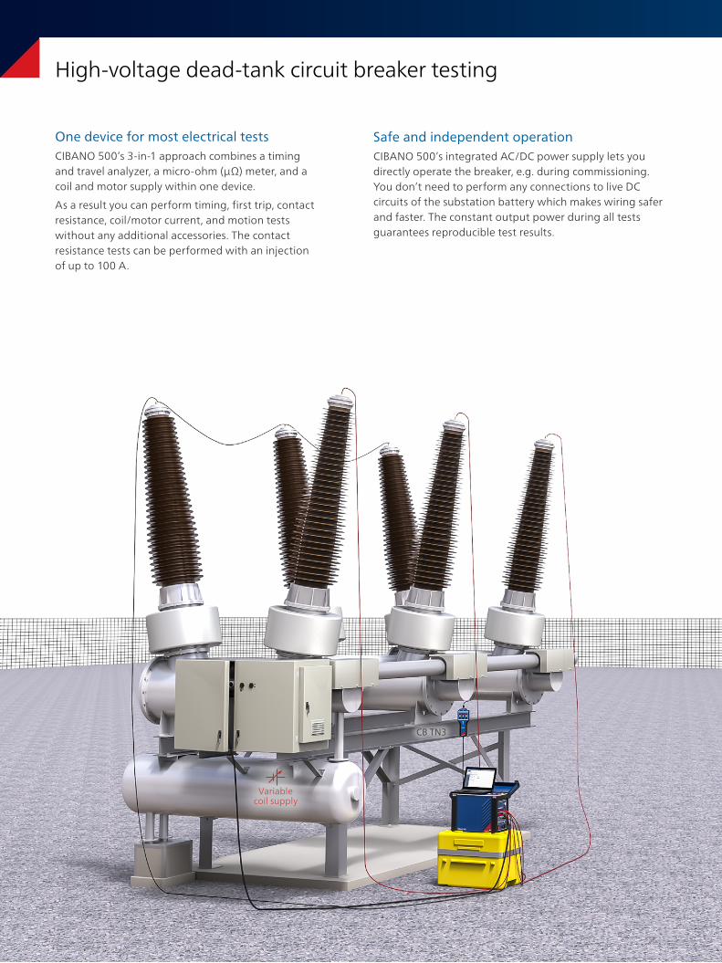
High-voltage dead-tank circuit breaker testing
CB TN3
Variable coil supply
Safe and independent operationCIBANO 500’s integrated AC/DC power supply lets you directly operate the breaker, e.g. during commissioning. You don’t need to perform any connections to live DC circuits of the substation battery which makes wiring safer and faster. The constant output power during all tests guarantees reproducible test results.
One device for most electrical testsCIBANO 500’s 3-in-1 approach combines a timing and travel analyzer, a micro-ohm (µΩ) meter, and a coil and motor supply within one device.
As a result you can perform timing, first trip, contact resistance, coil/motor current, and motion tests without any additional accessories. The contact resistance tests can be performed with an injection of up to 100 A.
11
First-trip test
The First trip test is carried out while the breaker is still in service. The signature of the measured trip coil current gives an indication of the tripping function. The opening times are measured by monitoring the CTs’ secondary current.
Dynamic contact resistance test
During this test, CIBANO 500 and the optional CB MC2 modules, record the contact resistance value during circuit breaker operation and deliver information about wear-related problems with main and arcing contacts.
CT demagnetization
The optional CT demagnetization function demagnetizes the integrated current transformers of the circuit breaker via the primary side. This makes sure that no residual magnetism affects the correct function of the CTs.
Common tests
> Timing
> First trip
> Static contact resistance
> Motion/contact travel
> Dynamic contact resistance test
> Coil/motor current analysis
> Under-voltage condition
> Minimum pick-up
Your benefits
> Contact resistance tests with up to 100 A
> Integrated power supply (2.4 kW) for safe and independent testing
> CT demagnetization
www.omicronenergy.com/cibano500
12
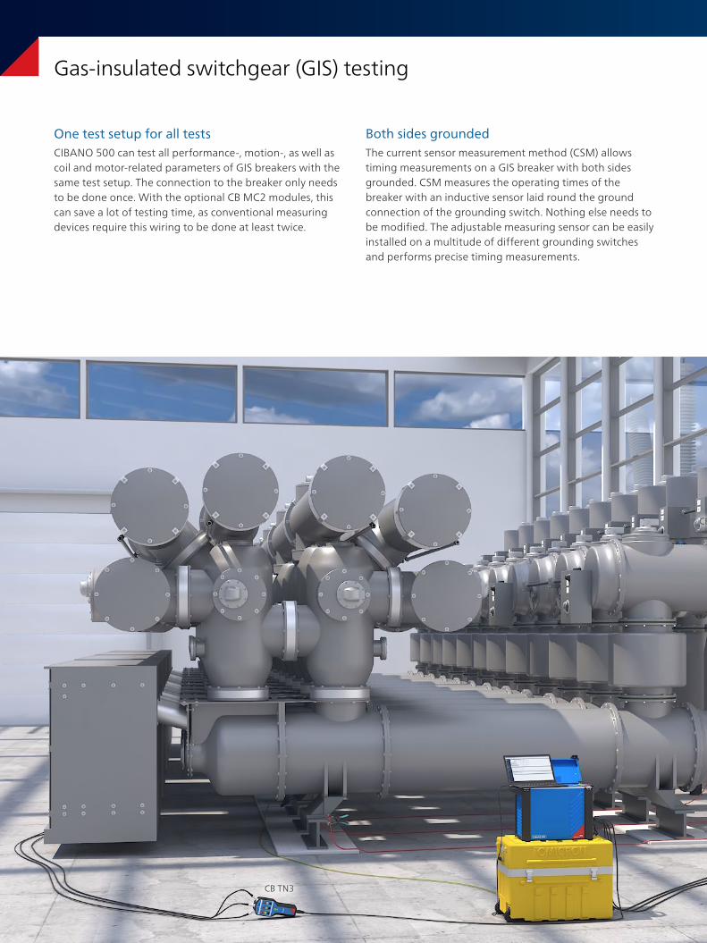
Gas-insulated switchgear (GIS) testing
Both sides groundedThe current sensor measurement method (CSM) allows timing measurements on a GIS breaker with both sides grounded. CSM measures the operating times of the breaker with an inductive sensor laid round the ground connection of the grounding switch. Nothing else needs to be modified. The adjustable measuring sensor can be easily installed on a multitude of different grounding switches and performs precise timing measurements.
One test setup for all testsCIBANO 500 can test all performance-, motion-, as well as coil and motor-related parameters of GIS breakers with the same test setup. The connection to the breaker only needs to be done once. With the optional CB MC2 modules, this can save a lot of testing time, as conventional measuring devices require this wiring to be done at least twice.
CB TN3
CB MC2
13
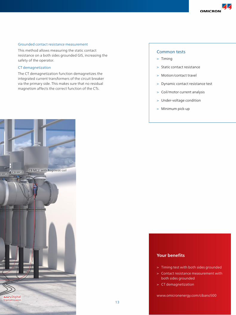
Grounded contact resistance measurement
This method allows measuring the static contact resistance on a both sides grounded GIS, increasing the safety of the operator.
CT demagnetization
The CT demagnetization function demagnetizes the integrated current transformers of the circuit breaker via the primary side. This makes sure that no residual magnetism affects the correct function of the CTs.
Common tests
> Timing
> Static contact resistance
> Motion/contact travel
> Dynamic contact resistance test
> Coil/motor current analysis
> Under-voltage condition
> Minimum pick-up
Your benefits
> Timing test with both sides grounded
> Contact resistance measurement with both sides grounded
> CT demagnetization
www.omicronenergy.com/cibano500
CB MC2CB MC2
CB MC2 with Rogowski coil
Digital transmission
14
> +
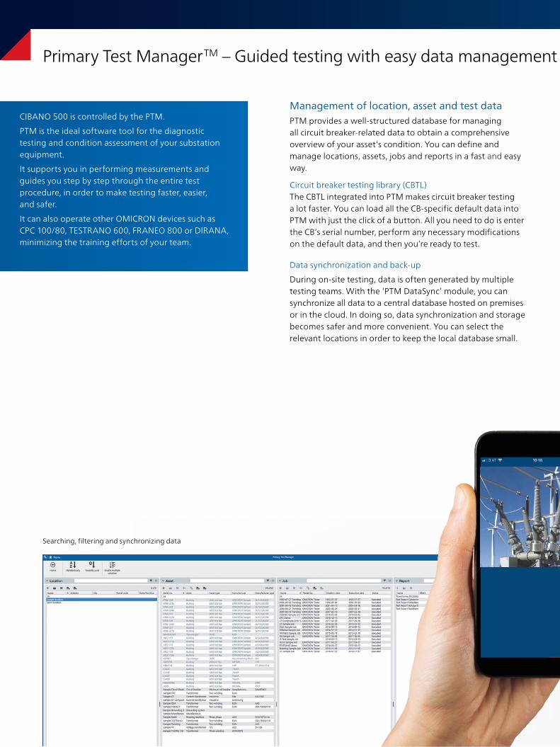
Primary Test Manager TM – Guided testing with easy data management and automatic result assessment
Management of location, asset and test dataPTM provides a well-structured database for managing all circuit breaker-related data to obtain a comprehensive overview of your asset’s condition. You can define and manage locations, assets, jobs and reports in a fast and easy way.
Circuit breaker testing library (CBTL)The CBTL integrated into PTM makes circuit breaker testing a lot faster. You can load all the CB-specific default data into PTM with just the click of a button. All you need to do is enter the CB’s serial number, perform any necessary modifications on the default data, and then you’re ready to test.
Data synchronization and back-up
During on-site testing, data is often generated by multiple testing teams. With the ‘PTM DataSync’ module, you can synchronize all data to a central database hosted on premises or in the cloud. In doing so, data synchronization and storage becomes safer and more convenient. You can select the relevant locations in order to keep the local database small.
Searching, filtering and synchronizing data
CIBANO 500 is controlled by the PTM.
PTM is the ideal software tool for the diagnostic testing and condition assessment of your substation equipment.
It supports you in performing measurements and guides you step by step through the entire test procedure, in order to make testing faster, easier, and safer.
It can also operate other OMICRON devices such as CPC 100/80, TESTRANO 600, FRANEO 800 or DIRANA, minimizing the training efforts of your team.
15
> +
Primary Test Manager TM – Guided testing with easy data management and automatic result assessment
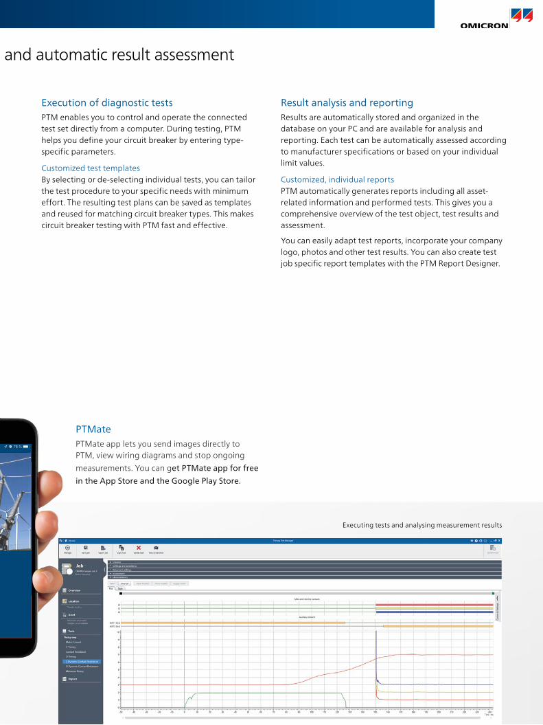
Execution of diagnostic tests PTM enables you to control and operate the connected test set directly from a computer. During testing, PTM helps you define your circuit breaker by entering type-specific parameters.
Customized test templatesBy selecting or de-selecting individual tests, you can tailor the test procedure to your specific needs with minimum effort. The resulting test plans can be saved as templates and reused for matching circuit breaker types. This makes circuit breaker testing with PTM fast and effective.
Result analysis and reporting Results are automatically stored and organized in the database on your PC and are available for analysis and reporting. Each test can be automatically assessed according to manufacturer specifications or based on your individual limit values.
Customized, individual reportsPTM automatically generates reports including all asset-related information and performed tests. This gives you a comprehensive overview of the test object, test results and assessment.
You can easily adapt test reports, incorporate your company logo, photos and other test results. You can also create test job specific report templates with the PTM Report Designer.
PTMatePTMate app lets you send images directly to PTM, view wiring diagrams and stop ongoing
measurements. You can get PTMate app for free
in the App Store and the Google Play Store.
Executing tests and analysing measurement results
16
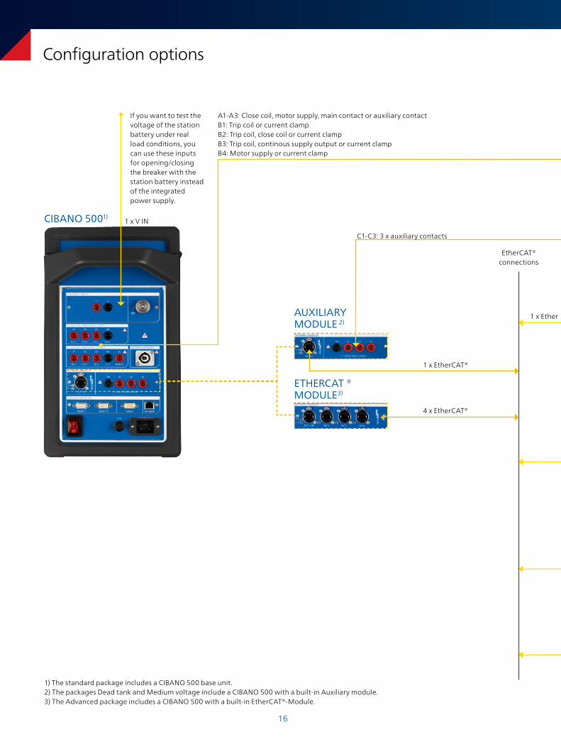
Configuration options
AUXILIARY MODULE 2)
If you want to test the voltage of the station battery under real load conditions, you can use these inputs for opening/closing the breaker with the station battery instead of the integrated power supply.
ETHERCAT ® MODULE3)
EtherCAT® connections
C1-C3: 3 x auxiliary contacts
1 x V IN
A1-A3: Close coil, motor supply, main contact or auxiliary contactB1: Trip coil or current clampB2: Trip coil, close coil or current clampB3: Trip coil, continous supply output or current clampB4: Motor supply or current clamp
CIBANO 5001)
1 x EtherCAT®
4 x EtherCAT®
1 x Ether CAT®
1) The standard package includes a CIBANO 500 base unit.2) The packages Dead tank and Medium voltage include a CIBANO 500 with a built-in Auxiliary module. 3) The Advanced package includes a CIBANO 500 with a built-in EtherCAT®-Module.
17
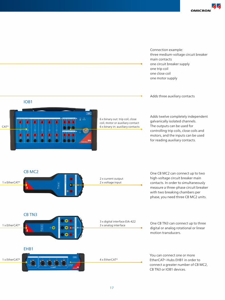
Adds three auxiliary contacts
One CB MC2 can connect up to two high-voltage circuit breaker main contacts. In order to simultaneously measure a three-phase circuit breaker with two breaking chambers per phase, you need three CB MC2 units.
One CB TN3 can connect up to three digital or analog rotational or linear motion transducers.
Connection example: three medium-voltage circuit breaker main contacts one circuit breaker supply one trip coil one close coil one motor supply
Adds twelve completely independent galvanically isolated channels. The outputs can be used for controlling trip coils, close coils and motors, and the inputs can be used for reading auxiliary contacts.
You can connect one or more EtherCAT®-Hubs EHB1 in order to connect a greater number of CB MC2, CB TN3 or IOB1 devices.
6 x binary out: trip coil, close coil, motor or auxiliary contact6 x binary in: auxiliary contacts
IOB1
1 x Ether CAT®
1 x EtherCAT®
1 x EtherCAT®
1 x EtherCAT®
CB MC2
CB TN3
EHB1
2 x current output2 x voltage input
3 x digital interface EIA-4223 x analog interface
4 x EtherCAT®
18
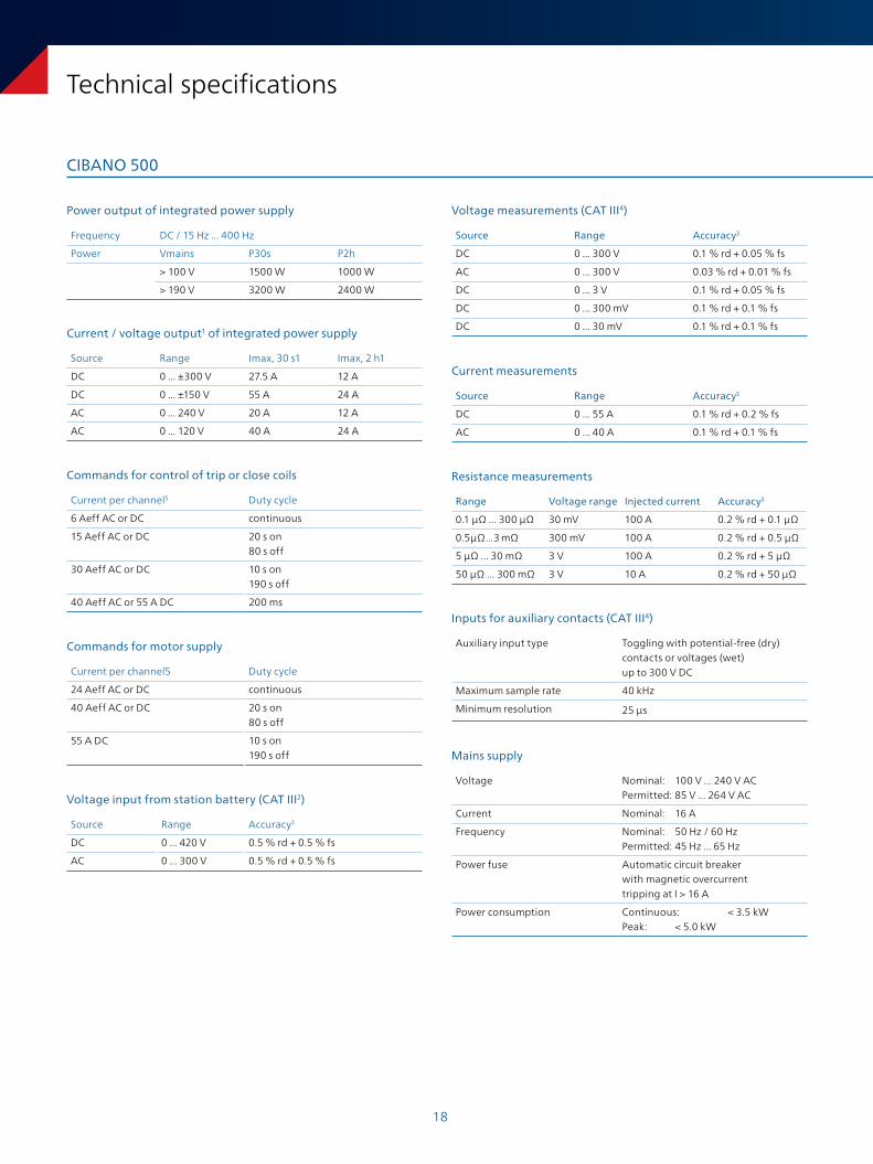
Technical specifications
CIBANO 500
Commands for control of trip or close coils
Current per channel5 Duty cycle
6 Aeff AC or DC continuous
15 Aeff AC or DC 20 s on 80 s off
30 Aeff AC or DC 10 s on 190 s off
40 Aeff AC or 55 A DC 200 ms
Current / voltage output1 of integrated power supply
Source Range Imax, 30 s1 Imax, 2 h1
DC 0 ... ±300 V 27.5 A 12 A
DC 0 ... ±150 V 55 A 24 A
AC 0 ... 240 V 20 A 12 A
AC 0 ... 120 V 40 A 24 A
Power output of integrated power supply
Frequency DC / 15 Hz ... 400 Hz
Power Vmains P30s P2h
> 100 V 1500 W 1000 W
> 190 V 3200 W 2400 W
Commands for motor supply
Current per channel5 Duty cycle
24 Aeff AC or DC continuous
40 Aeff AC or DC 20 s on 80 s off
55 A DC 10 s on 190 s off
Voltage input from station battery (CAT III2)
Source Range Accuracy3
DC 0 ... 420 V 0.5 % rd + 0.5 % fs
AC 0 ... 300 V 0.5 % rd + 0.5 % fs
Inputs for auxiliary contacts (CAT III4)
Auxiliary input type Toggling with potential-free (dry) contacts or voltages (wet) up to 300 V DC
Maximum sample rate 40 kHz
Minimum resolution 25 μs
Mains supply
Voltage Nominal: 100 V ... 240 V AC Permitted: 85 V ... 264 V AC
Current Nominal: 16 A
Frequency Nominal: 50 Hz / 60 Hz Permitted: 45 Hz ... 65 Hz
Power fuse Automatic circuit breaker with magnetic overcurrent tripping at I > 16 A
Power consumption Continuous: < 3.5 kW Peak: < 5.0 kW
Voltage measurements (CAT III4)
Source Range Accuracy3
DC 0 ... 300 V 0.1 % rd + 0.05 % fs
AC 0 ... 300 V 0.03 % rd + 0.01 % fs
DC 0 ... 3 V 0.1 % rd + 0.05 % fs
DC 0 ... 300 mV 0.1 % rd + 0.1 % fs
DC 0 ... 30 mV 0.1 % rd + 0.1 % fs
Current measurements
Source Range Accuracy3
DC 0 ... 55 A 0.1 % rd + 0.2 % fs
AC 0 ... 40 A 0.1 % rd + 0.1 % fs
Resistance measurements
Range Voltage range Injected current Accuracy3
0.1 μΩ ... 300 µΩ 30 mV 100 A 0.2 % rd + 0.1 μΩ
0.5 μΩ ... 3 mΩ 300 mV 100 A 0.2 % rd + 0.5 μΩ
5 μΩ ... 30 mΩ 3 V 100 A 0.2 % rd + 5 μΩ
50 μΩ ... 300 mΩ 3 V 10 A 0.2 % rd + 50 μΩ
19
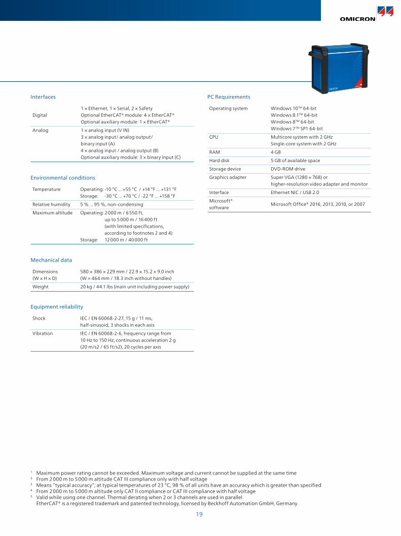
Environmental conditions
Temperature Operating: -10 °C ... +55 °C / +14 °F ... +131 °F Storage: -30 °C ... +70 °C / -22 °F ... +158 °F
Relative humidity 5 % ... 95 %, non-condensing
Maximum altitude Operating: 2 000 m / 6 550 ft, up to 5 000 m / 16 400 ft (with limited specifications, according to footnotes 2 and 4)Storage: 12 000 m / 40 000 ft
Mechanical data
Dimensions (W × H × D)
580 × 386 × 229 mm / 22.9 × 15.2 × 9.0 inch(W = 464 mm / 18.3 inch without handles)
Weight 20 kg / 44.1 lbs (main unit including power supply)
Equipment reliability
Shock IEC / EN 60068-2-27, 15 g / 11 ms, half-sinusoid, 3 shocks in each axis
Vibration IEC / EN 60068-2-6, frequency range from 10 Hz to 150 Hz, continuous acceleration 2 g (20 m/s2 / 65 ft/s2), 20 cycles per axis
Interfaces
Digital1 × Ethernet, 1 × Serial, 2 × Safety Optional EtherCAT® module: 4 × EtherCAT® Optional auxiliary module: 1 × EtherCAT®
Analog 1 × analog input (V IN)3 × analog input/ analog output/ binary input (A)4 × analog input / analog output (B)Optional auxiliary module: 3 × binary input (C)
PC Requirements
Operating system Windows 10TM 64-bitWindows 8.1TM 64-bitWindows 8TM 64-bitWindows 7TM SP1 64-bit
CPU Multicore system with 2 GHzSingle-core system with 2 GHz
RAM 4 GB
Hard disk 5 GB of available space
Storage device DVD-ROM drive
Graphics adapter Super VGA (1280 × 768) orhigher-resolution video adapter and monitor
Interface Ethernet NIC / USB 2.0
Microsoft® software
Microsoft Office® 2016, 2013, 2010, or 2007
1 Maximum power rating cannot be exceeded. Maximum voltage and current cannot be supplied at the same time2 From 2 000 m to 5 000 m altitude CAT III compliance only with half voltage3 Means “typical accuracy”; at typical temperatures of 23 °C, 98 % of all units have an accuracy which is greater than specified4 From 2 000 m to 5 000 m altitude only CAT II compliance or CAT III compliance with half voltage5 Valid while using one channel. Thermal derating when 2 or 3 channels are used in parallel EtherCAT® is a registered trademark and patented technology, licensed by Beckhoff Automation GmbH, Germany.
20
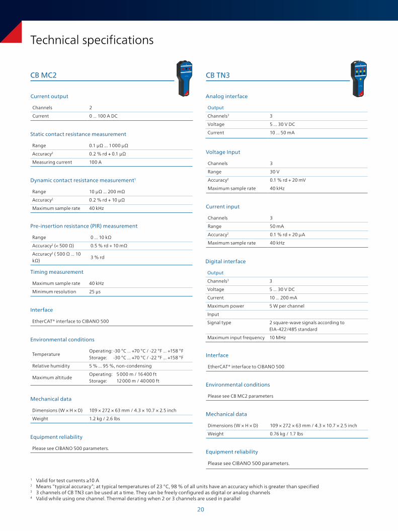
Technical specifications
CB MC2 CB TN3
Voltage Input
Channels 3
Range 30 V
Accuracy2 0.1 % rd + 20 mV
Maximum sample rate 40 kHz
Environmental conditions
Please see CB MC2 parameters
Mechanical data
Dimensions (W × H × D) 109 × 272 × 63 mm / 4.3 × 10.7 × 2.5 inch
Weight 0.76 kg / 1.7 lbs
Equipment reliability
Please see CIBANO 500 parameters.
Interface
EtherCAT® interface to CIBANO 500
Current input
Channels 3
Range 50 mA
Accuracy2 0.1 % rd + 20 µA
Maximum sample rate 40 kHz
Digital interface
Output
Channels3 3
Voltage 5 ... 30 V DC
Current 10 ... 200 mA
Maximum power 5 W per channel
Input
Signal type 2 square-wave signals according to EIA-422/485 standard
Maximum input frequency 10 MHz
Analog interface
Output
Channels3 3
Voltage 5 ... 30 V DC
Current 10 ... 50 mA
Current output
Channels 2
Current 0 ... 100 A DC
Static contact resistance measurement
Range 0.1 μΩ ... 1 000 μΩ
Accuracy2 0.2 % rd + 0.1 μΩ
Measuring current 100 A
Dynamic contact resistance measurement1
Range 10 µΩ ... 200 mΩ
Accuracy2 0.2 % rd + 10 µΩ
Maximum sample rate 40 kHz
Pre-insertion resistance (PIR) measurement
Range 0 ... 10 kΩ
Accuracy2 (< 500 Ω) 0.5 % rd + 10 mΩ
Accuracy2 ( 500 Ω ... 10 kΩ)
3 % rd
Timing measurement
Maximum sample rate 40 kHz
Minimum resolution 25 μs
Interface
EtherCAT® interface to CIBANO 500
Environmental conditions
Temperature Operating: -30 °C ... +70 °C / -22 °F ... +158 °FStorage: -30 °C ... +70 °C / -22 °F ... +158 °F
Relative humidity 5 % ... 95 %, non-condensing
Maximum altitudeOperating: 5 000 m / 16 400 ftStorage: 12 000 m / 40 000 ft
Mechanical data
Dimensions (W × H × D) 109 × 272 × 63 mm / 4.3 × 10.7 × 2.5 inch
Weight 1.2 kg / 2.6 lbs
Equipment reliability
Please see CIBANO 500 parameters.
1 Valid for test currents ≥10 A2 Means “typical accuracy”; at typical temperatures of 23 °C, 98 % of all units have an accuracy which is greater than specified3 3 channels of CB TN3 can be used at a time. They can be freely configured as digital or analog channels4 Valid while using one channel. Thermal derating when 2 or 3 channels are used in parallel
21
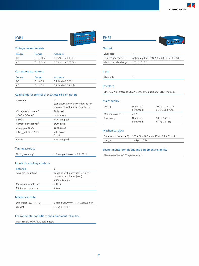
EHB1
Output
Channels 4
Devices per channel optionally 1 × CB MC2, 1 × CB TN3 or 1 × IOB1
Maximum cable length 100 m / 328 ft
Interface
EtherCAT® interface to CIBANO 500 or to additional EHB1 modules
Environmental conditions and equipment reliability
Please see CIBANO 500 parameters.
Mechanical data
Dimensions (W × H × D) 265 × 80 × 180 mm / 10.4 × 3.1 × 7.1 inch
Weight 1.8 kg / 4.0 lbs
IOB1
Input
Channels 1
Mains supply
Voltage Nominal: 100 V ... 240 V AC Permitted: 85 V ... 264 V AC
Maximum current 2.5 A
Frequency Nominal: 50 Hz / 60 Hz Permitted: 45 Hz ... 65 Hz
Voltage measurements
Source Range Accuracy2
DC 0 ... 300 V 0.05 % rd + 0.05 % fs
AC 0 ... 300 V 0.05 % rd + 0.02 % fs
Current measurements
Source Range Accuracy2
DC 0 ... 40 A 0.1 % rd + 0.2 % fs
AC 0 ... 40 A 0.1 % rd + 0.05 % fs
Timing accuracy
Timing accuracy2 ± 1 sample interval ± 0.01 % rd
Inputs for auxiliary contacts
Channels 6
Auxiliary input type Toggling with potential-free (dry) contacts or voltages (wet) up to 300 V DC
Maximum sample rate 40 kHz
Minimum resolution 25 μs
Environmental conditions and equipment reliability
Please see CIBANO 500 parameters.
Mechanical data
Dimensions (W × H × D) 381 × 190 × 90 mm / 15 × 7.5 × 3.5 inch
Weight 3.0 kg / 6.6 lbs
Commands for control of trip/close coils or motors
Channels 6 (can alternatively be configured for measuring wet auxiliary contacts)
Voltage per channel⁴ Duty cycle
± 300 V DC or AC continuous
± 500 V transient peak
Current per channel⁴ Duty cycle
24 ARMS AC or DC continuous
40 ARMS AC or 55 A DC 200 ms on 5s off
± 85 A transient peak

100%routine testing for all test set components
ISO 9001
ISO 14001OHSAS 18001
TÜV & EMAS
Compliance with international standards
15%of our annual sales is reinvested in research and development
More than
ISO 9001
You can rely on the highest safety and security standards
72%
hours burn-in tests before delivery
Superior reliability with up to
200More than
developers keep our solutions up-to-date
70%Save up to
testing time through templates, and automation
InnovationQuality
We create customer value through ...
... a product portfolio tailored to my needs
I need...
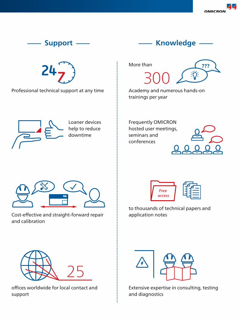
Professional technical support at any time
Loaner devices help to reduce downtime
300???
Academy and numerous hands-on trainings per year
More than
Cost-eff ective and straight-forward repair and calibration
Frequently OMICRON hosted user meetings, seminars and conferences
25offi ces worldwide for local contact and support
Support Knowledge
to thousands of technical papers and application notes
Free access
Extensive expertise in consulting, testing and diagnostics
100%routine testing for all test set components
ISO 9001
ISO 14001OHSAS 18001
TÜV & EMAS
Compliance with international standards
15%of our annual sales is reinvested in research and development
More than
ISO 9001
You can rely on the highest safety and security standards
72%
hours burn-in tests before delivery
Superior reliability with up to
200More than
developers keep our solutions up-to-date
70%Save up to
testing time through templates, and automation
InnovationQuality
We create customer value through ...
... a product portfolio tailored to my needs
I need...
Professional technical support at any time
Loaner devices help to reduce downtime
300???
Academy and numerous hands-on trainings per year
More than
Cost-eff ective and straight-forward repair and calibration
Frequently OMICRON hosted user meetings, seminars and conferences
25offi ces worldwide for local contact and support
Support Knowledge
to thousands of technical papers and application notes
Free access
Extensive expertise in consulting, testing and diagnostics
Subject to change without notice.www.omicronenergy.com
For more information, additional literature, and detailed contact information of our worldwide offices please visit our website.
© OMICRON L4023, 01 2022
The following publication provides further information on the Primary Test Manager TM:
PTM Brochure
OMICRON is an international company that works passionately on ideas for making electric power systems safe and reliable. Our pioneering solutions are designed to meet our industry’s current and future challenges. We always go the extra mile to empower our customers: we react to their needs, provide extraordinary local support, and share our expertise.
Within the OMICRON group, we research and develop innovative technologies for all fields in electric power systems. When it comes to electrical testing for medium- and high-voltage equipment, protection testing, digital substation testing solutions, and cybersecurity solutions, customers all over the world trust in the accuracy, speed, and quality of our user-friendly solutions.
Founded in 1984, OMICRON draws on their decades of profound expertise in the field of electric power engineering. A dedicated team of more than 900 employees provides solutions with 24/7 support at 25 locations worldwide and serves customers in more than 160 countries.
. L4023