2mm Analysis of Time Series 2mm Chapter 6: Extending the ...
Advanced Soil Mechanics I
SNU Geotechnical and Geoenvironmental Engineering Lab.
2-1 Chapter II
Deformation Analysis
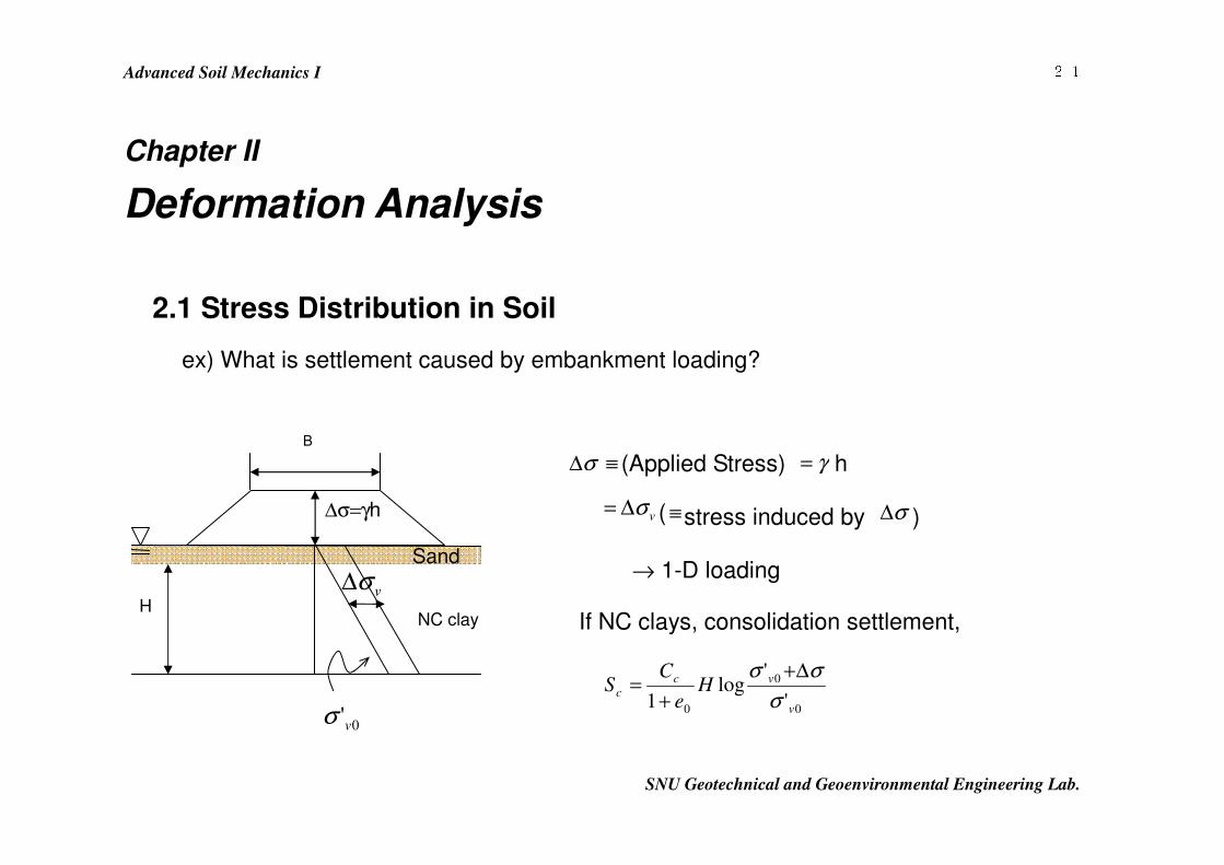
2.1 Stress Distribution in Soil
ex) What is settlement caused by embankment loading?
σ∆ ≡ (Applied Stress) γ= h
vσ∆= ( ≡stress induced by σ∆ )
→ 1-D loading
If NC clays, consolidation settlement,
0
0
0 '
'log
1 v
vc
c He
CS
σσσ ∆+
+=
B
∆σ=γh
NC clay
Sand
vσ∆
0'vσ
H
Advanced Soil Mechanics I
SNU Geotechnical and Geoenvironmental Engineering Lab.
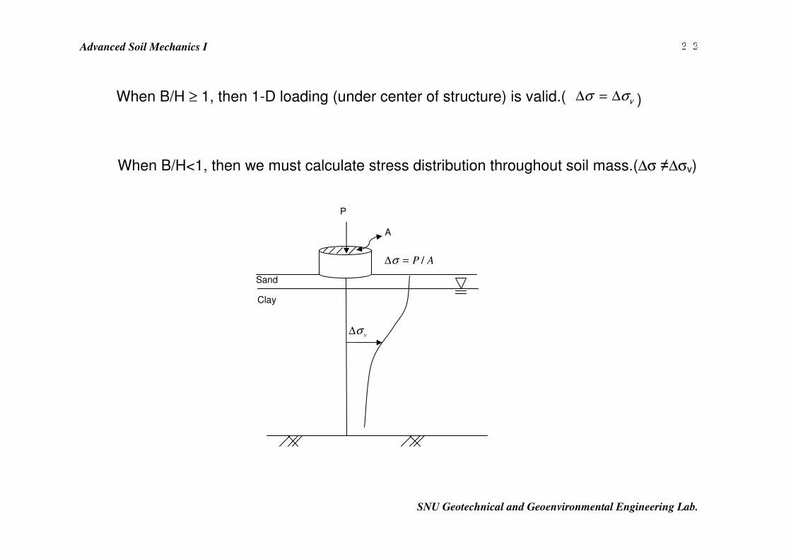
2-2 When B/H ≥ 1, then 1-D loading (under center of structure) is valid.( vσ σ∆ = ∆ )
When B/H<1, then we must calculate stress distribution throughout soil mass.(∆σ ≠∆σv)
P
vσ∆ A
Sand
Clay
AP /=∆σ
Advanced Soil Mechanics I
SNU Geotechnical and Geoenvironmental Engineering Lab.
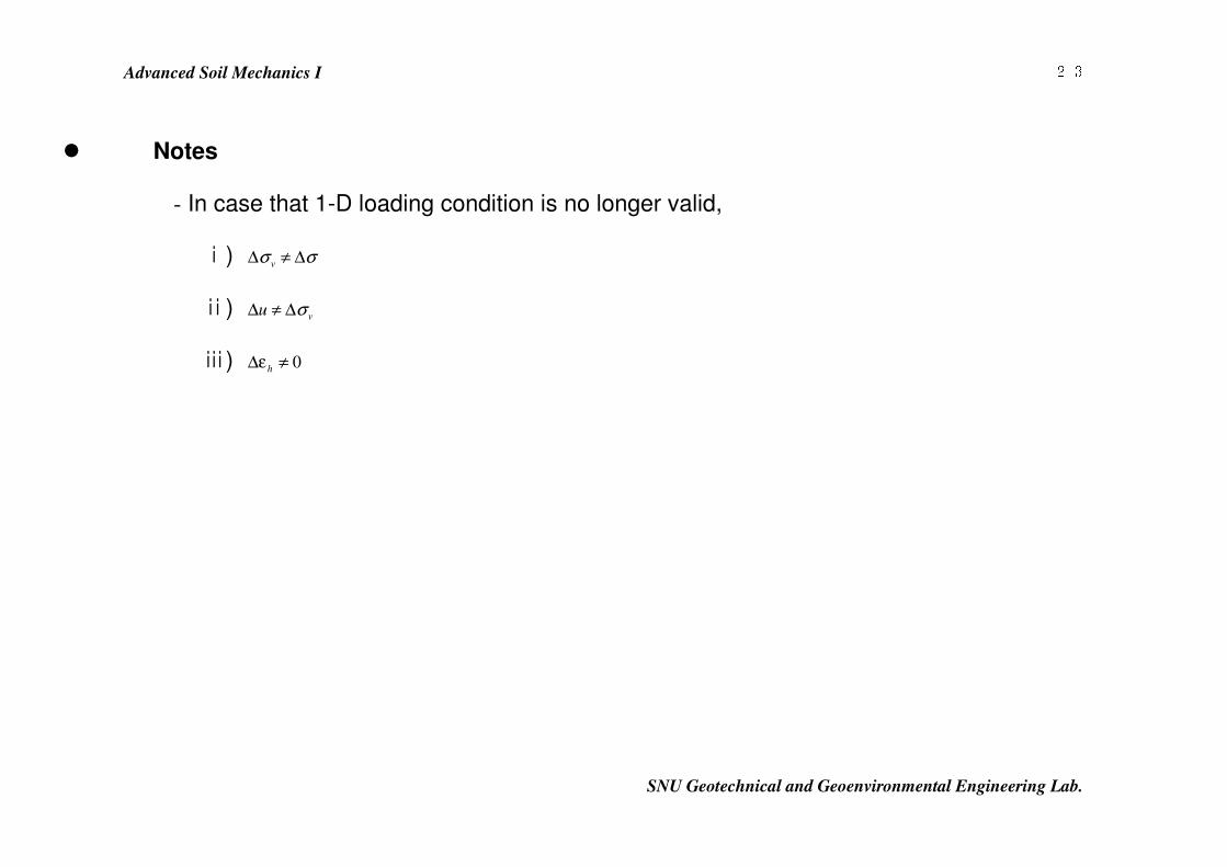
2-3 � Notes
- In case that 1-D loading condition is no longer valid,
ⅰ) σσ ∆≠∆ v
ⅱ) vu σ∆≠∆
ⅲ) 0≠ε∆ h
Advanced Soil Mechanics I
SNU Geotechnical and Geoenvironmental Engineering Lab.
2-4 � Use elasticity to calculate the stress distribution.
⇒ Boussinesq approach.
Assumptions
1. Soil is homogeneous and isotropic.
2. Soil is linear elastic.
3. Semi-infinite soil mass (No rigid base nearby).
4. Perfectly flexible footing.
Advanced Soil Mechanics I
SNU Geotechnical and Geoenvironmental Engineering Lab.
2-5 Can get
1. good estimate of vσ∆ .
2. but poor estimate of hσ∆ (unless plane strain condition)
↑
L/B ≥ 5
( → Generally consolidation settlement is estimated by vu σ∆=∆ and 0hε = )
Advanced Soil Mechanics I
SNU Geotechnical and Geoenvironmental Engineering Lab.
2-6 � Stress Distributions
- Point load : depth ≥ 3 times of width(diameter) of square ft (circular ft).
- Line load : depth ≥ 3 times of width of strip ft.
Advanced Soil Mechanics I
SNU Geotechnical and Geoenvironmental Engineering Lab.
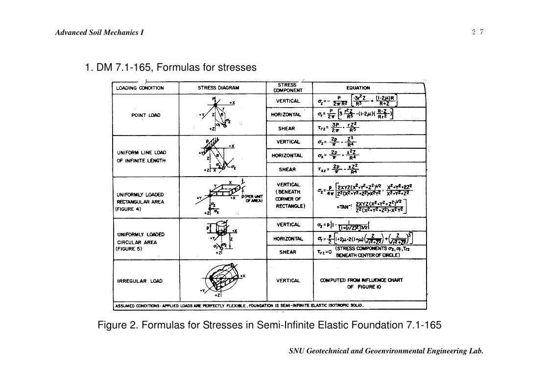
2-7 1. DM 7.1-165, Formulas for stresses
Figure 2. Formulas for Stresses in Semi-Infinite Elastic Foundation 7.1-165
Advanced Soil Mechanics I
SNU Geotechnical and Geoenvironmental Engineering Lab.
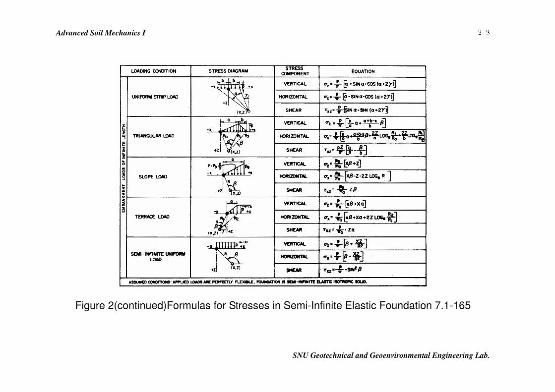
2-8
Figure 2(continued)Formulas for Stresses in Semi-Infinite Elastic Foundation 7.1-165
Advanced Soil Mechanics I
SNU Geotechnical and Geoenvironmental Engineering Lab.
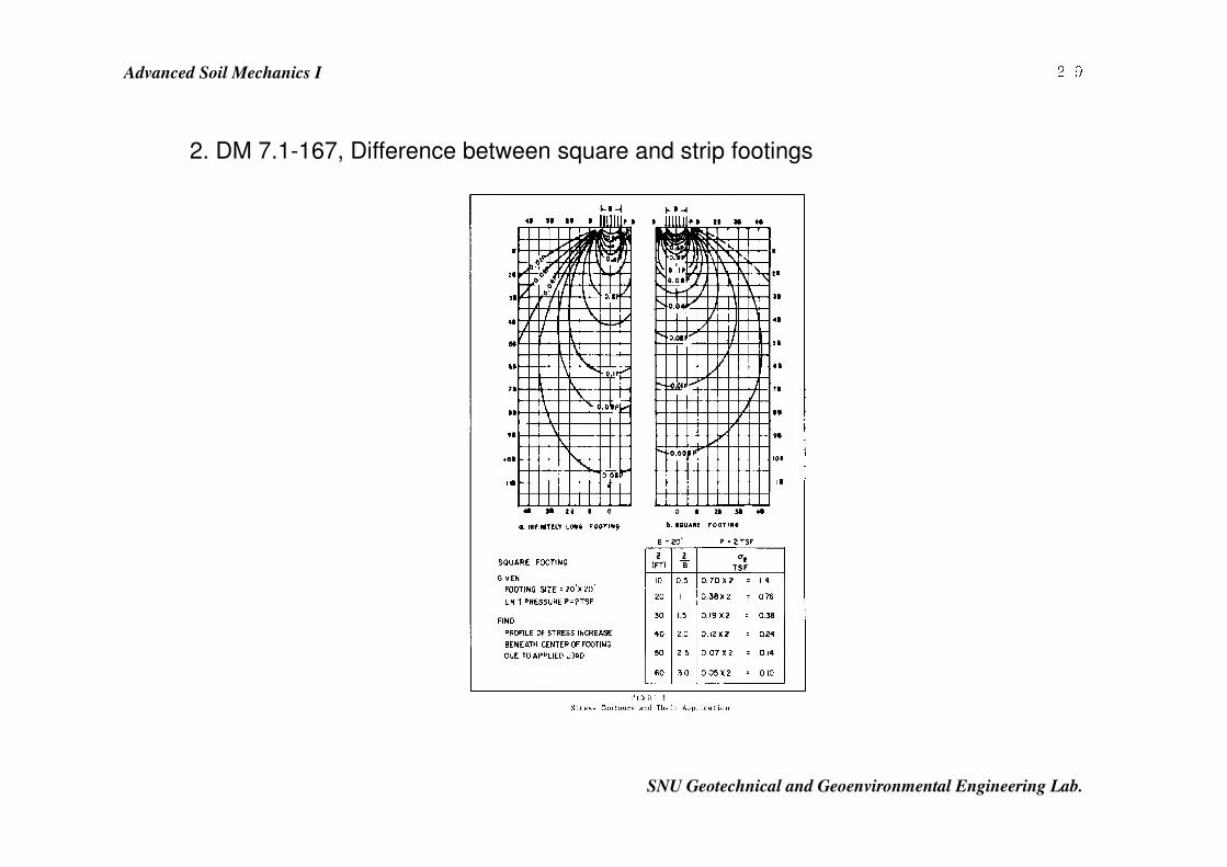
2-9 2. DM 7.1-167, Difference between square and strip footings
Advanced Soil Mechanics I
SNU Geotechnical and Geoenvironmental Engineering Lab.
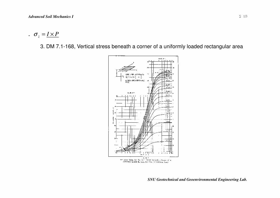
2-10- PIz ×=σ
3. DM 7.1-168, Vertical stress beneath a corner of a uniformly loaded rectangular area
Advanced Soil Mechanics I
SNU Geotechnical and Geoenvironmental Engineering Lab.
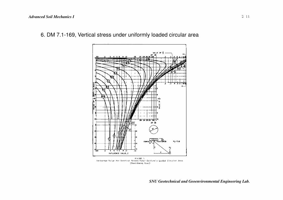
2-116. DM 7.1-169, Vertical stress under uniformly loaded circular area
Advanced Soil Mechanics I
SNU Geotechnical and Geoenvironmental Engineering Lab.
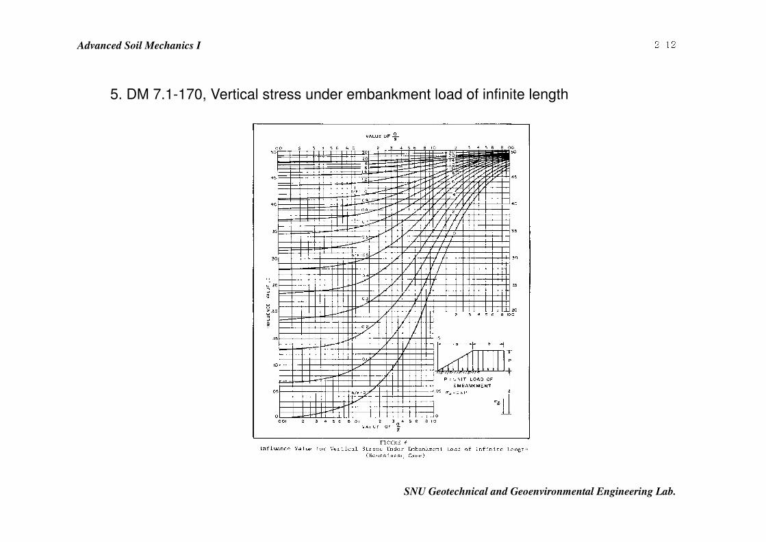
2-125. DM 7.1-170, Vertical stress under embankment load of infinite length
Advanced Soil Mechanics I
SNU Geotechnical and Geoenvironmental Engineering Lab.
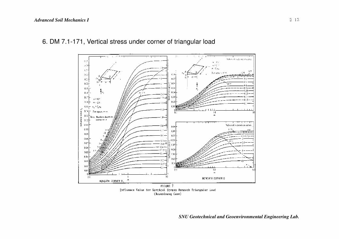
2-136. DM 7.1-171, Vertical stress under corner of triangular load
Advanced Soil Mechanics I
SNU Geotechnical and Geoenvironmental Engineering Lab.
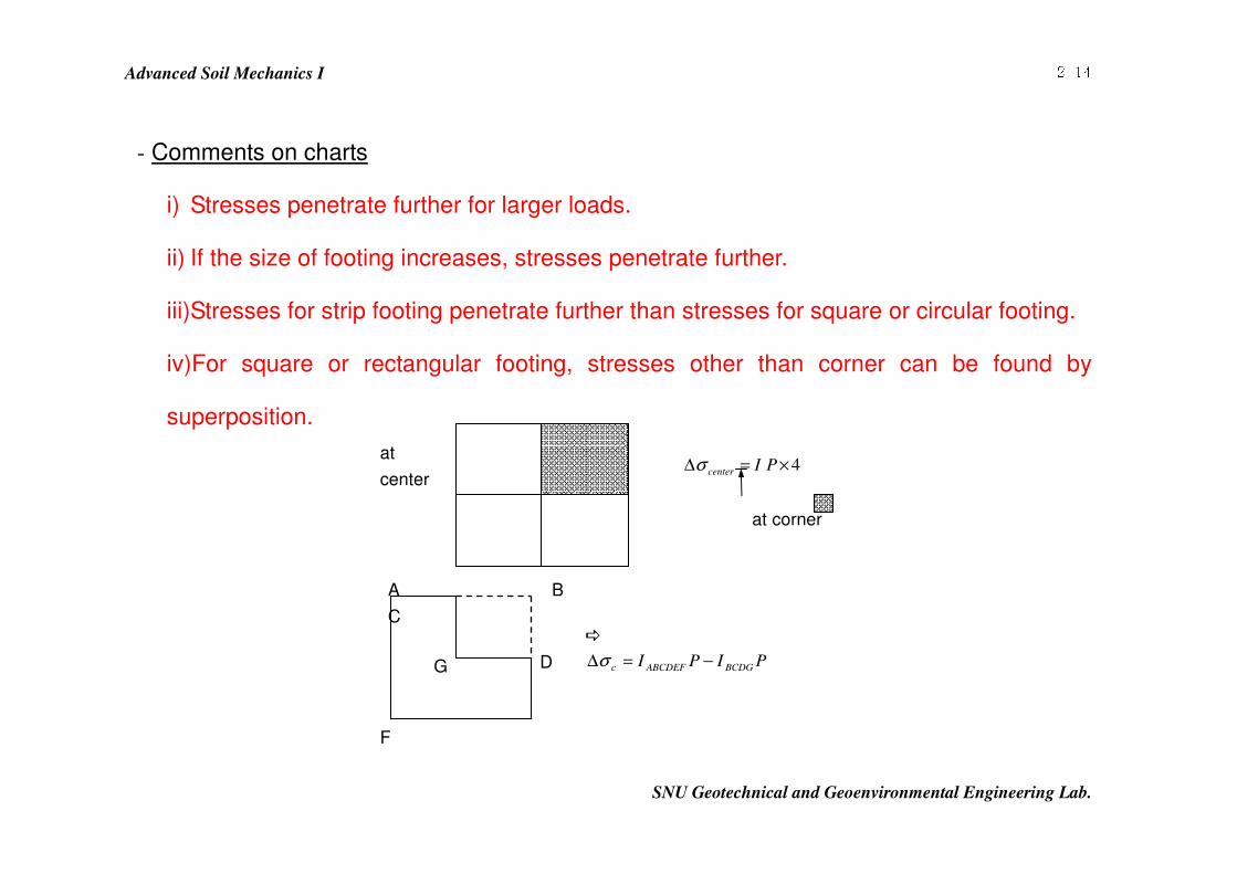
2-14- Comments on charts
i) Stresses penetrate further for larger loads.
ii) If the size of footing increases, stresses penetrate further.
iii) Stresses for strip footing penetrate further than stresses for square or circular footing.
iv)For square or rectangular footing, stresses other than corner can be found by
superposition.
at
center 4×=∆ PIcenter σ
at corner
�
PIPI BCDGABCDEFc −=∆σ
A B
C
F
G D
Advanced Soil Mechanics I
SNU Geotechnical and Geoenvironmental Engineering Lab.
2-15- Rule of thumb to find critical depth
critical depth : depth at which soil compression contributes significantly to surface
settlements
i) Sands Depth at which vσ∆ is 20% of the in situ, effective stresses( vo
'σ )
ii) Clays ≥∆ vσ 10% of vo
'σ
Advanced Soil Mechanics I
SNU Geotechnical and Geoenvironmental Engineering Lab.
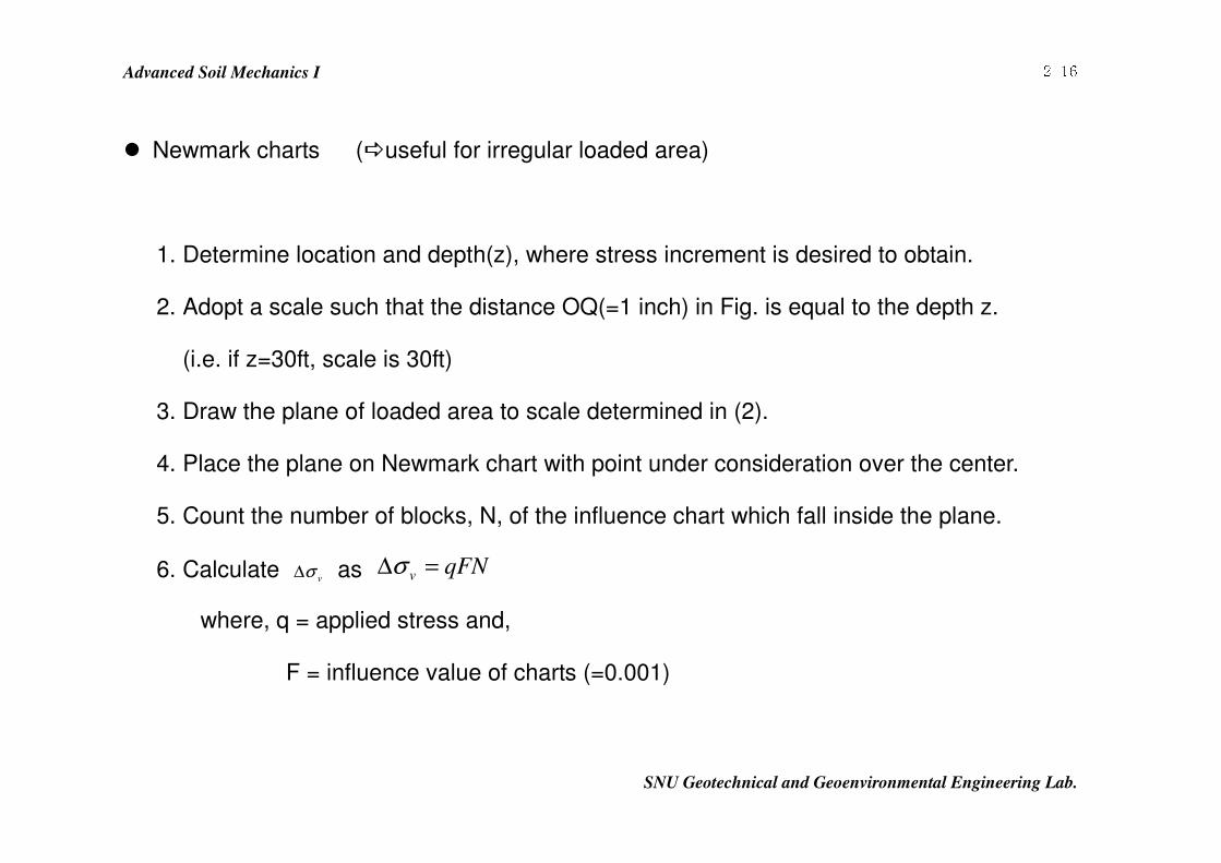
2-16� Newmark charts (�useful for irregular loaded area)
1. Determine location and depth(z), where stress increment is desired to obtain.
2. Adopt a scale such that the distance OQ(=1 inch) in Fig. is equal to the depth z.
(i.e. if z=30ft, scale is 30ft)
3. Draw the plane of loaded area to scale determined in (2).
4. Place the plane on Newmark chart with point under consideration over the center.
5. Count the number of blocks, N, of the influence chart which fall inside the plane.
6. Calculate vσ∆ as qFNv =∆σ
where, q = applied stress and,
F = influence value of charts (=0.001)
Advanced Soil Mechanics I
SNU Geotechnical and Geoenvironmental Engineering Lab.
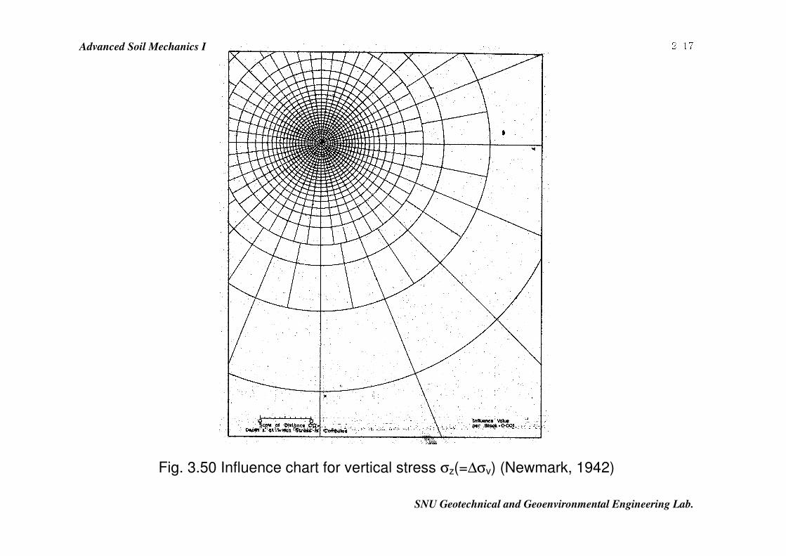
2-17
Fig. 3.50 Influence chart for vertical stress σz(=∆σv) (Newmark, 1942)
Advanced Soil Mechanics I
SNU Geotechnical and Geoenvironmental Engineering Lab.
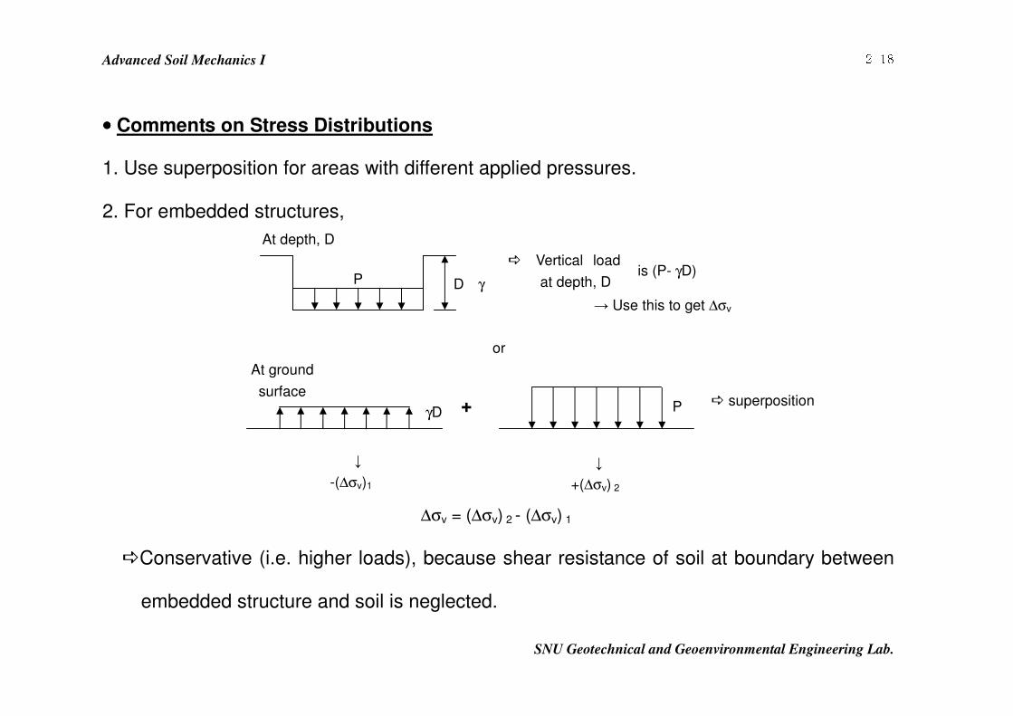
2-18•••• Comments on Stress Distributions
1. Use superposition for areas with different applied pressures.
2. For embedded structures,
�Conservative (i.e. higher loads), because shear resistance of soil at boundary between
embedded structure and soil is neglected.
→ Use this to get ∆σv
� superposition
↓
-(∆σv)1
↓
+(∆σv) 2
∆σv = (∆σv) 2 - (∆σv) 1
D γ P
� Vertical load
at depth, D is (P- γD)
or
γD + P
At ground
surface
At depth, D
Advanced Soil Mechanics I
SNU Geotechnical and Geoenvironmental Engineering Lab.
2-19
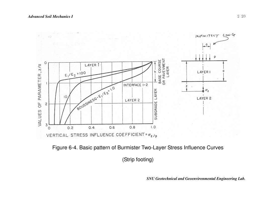
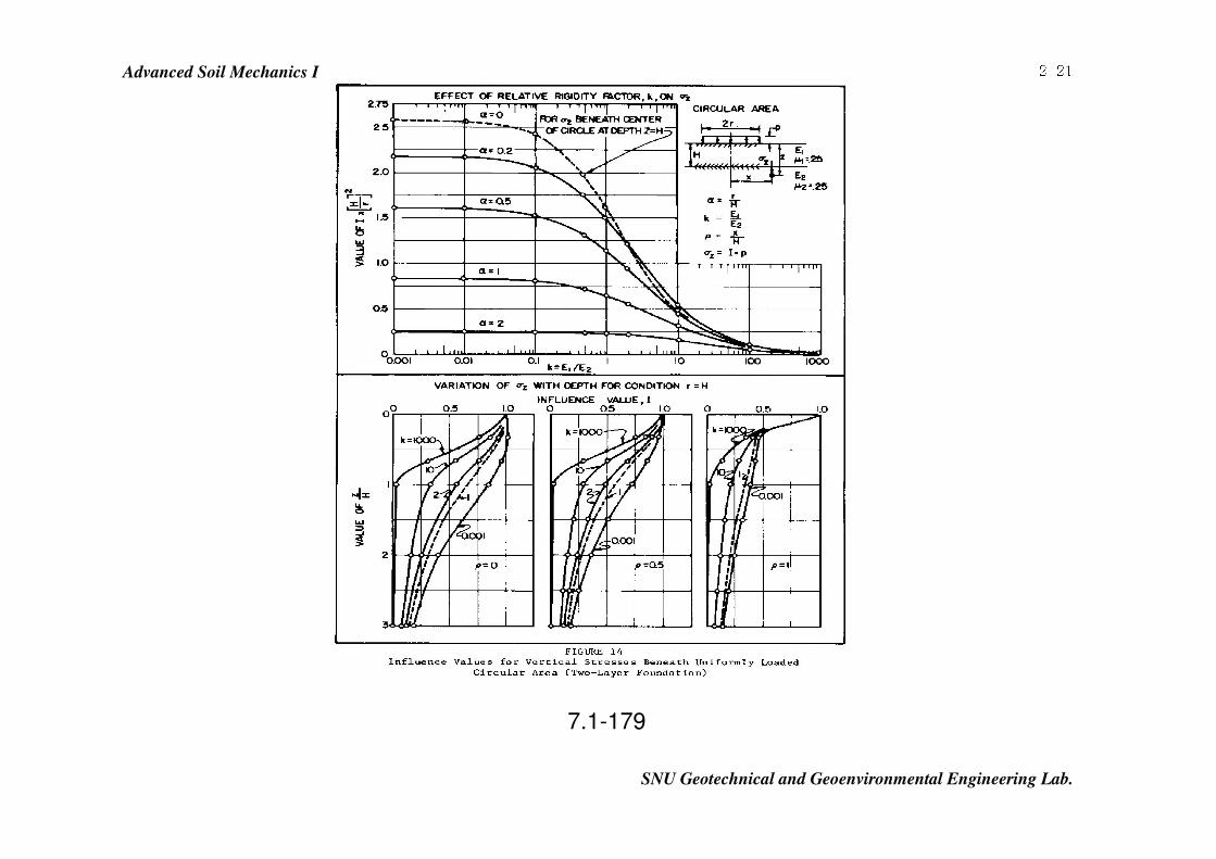
3. Vertical stresses are affected by layering, if soils have much different E values.
4. Stiff layer at ground surface dissipates the induced stresses rapidly.
(Hand out Fig 6-4 in p2-15, 7.1-179 in p2-16)
Advanced Soil Mechanics I
SNU Geotechnical and Geoenvironmental Engineering Lab.
2-20
Figure 6-4. Basic pattern of Burmister Two-Layer Stress Influence Curves
(Strip footing)
Advanced Soil Mechanics I
SNU Geotechnical and Geoenvironmental Engineering Lab.
2-21
7.1-179