Chapter 5 - Sonoma State University Modulation – Basic Concepts ! Note that θ’(t) Referred as...
34
Chapter 5 Angle Modulation Updated: 4/6/15
Transcript of Chapter 5 - Sonoma State University Modulation – Basic Concepts ! Note that θ’(t) Referred as...
Chapter 5
Angle Modulation Updated: 4/6/15
Outline • Angle Modulation

Review: Modulation Concept • Modulation is the process by which a message or
information-bearing signal is transformed into another signal to facilitate transmission over a communication channel – Requires an auxiliary signal called carrier – The modulation process is performed to accomplish several
objectives
• Modulation Objectives – Frequency translation
• Designating various frequency spectrum for difference applications – Channelization
• E.g., assigning difference channels for uploading and downloading – Practical Equipment Design
• Antenna size (λf=c) – Noise Performance
• Assigning higher BW to ensure higher noise performance • E.g., FM has 200-KHz channel BW compared to 10KHz for AM

Review: Bandpass Signal & AM Modulation • Remember for bandpass waveform we have
• The voltage (or current) spectrum of the bandpass signal is
• The PSD will be
• In case of Ordinary AM (DSB – FC) modulation:
• In this case Ac is the power level of the carrier signal with no modulation;
• Therefore:
e
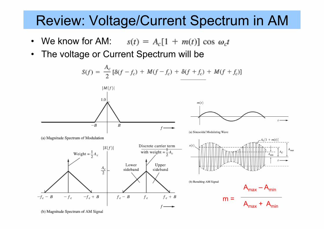
Review: Voltage/Current Spectrum in AM • We know for AM: • The voltage or Current Spectrum will be
Amax – Amin Amax + Amin
m =

Angle Modulation – Basic Concepts
à Note that θ’(t) Referred as the instantaneous frequency deviation
Phase deviation sensitivity (rad/V)
Freq. deviation sensitivity in rad/sec
Definitions: • θ(t) is the instantaneous phase deviation (excess phase) - radian • θ’(t) is the instantaneous frequency deviation – radian/sec • Φi(t)=ωct + θ(t) is the instantaneous phase (exact) - radian • fi(t)=(1/2p)dΦι(t)/dt = d(ωct + θ(t))/dt
• This is the instantaneous frequency (exact) – radian/sec
Φi(t)

Angle Modulation Representation
Constant called Phase deviation sensitivity (rad/V)
Constant called Freq. deviation sensitivity in ((rad/sec)/V)
In PM: θ(t) is proportional to m(t) à θ(t) = Dp . m(t) àθ’(t) = Dp . d [m(t)] / dt à Max. Instant. Frequency Deviation at Zero Crossing!
In FM: θ’(t) is proportional to m(t) à θ’(t) = Df . m(t)
à Max. Instant. Frequency Deviation at max[m(t)]
or Df/2π = Hz/V

Frequency VS Phase Modulation
Frequency Modulation
Phase Modulation
θ’(t) = Dp . d [m(t)] / dt
θ’(t) = Df . m(t)

Frequency VS Phase Modulation
Frequency Modulation
Phase Modulation
θ’(t) = Dp . d [m(t)] / dt
θ’(t) = Df . m(t)
Max. Instant. Frequency Deviation at max[m(t)]
Max. Instant. Frequency Deviation at Zero Crossing
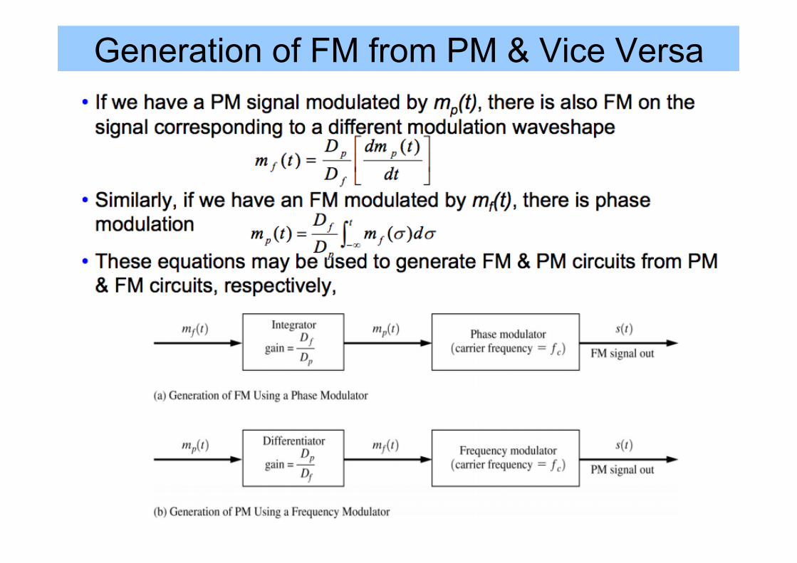
Generation of FM from PM & Vice Versa

Frequency Deviation • In general
– For FM
– Thus, in case of FM
– For PM
– Thus, in case of PM p
,
The instantaneous freq. varies about carrier freq. proportional to m(t)
Frequency deviation from the carrier frequency
Derivative of m(t)

Maximum Frequency Deviation

Angle Modulation Using MATLAB

Assuming the Modulating Signal is Sinusoid s(t) =Vc cos(ωct +θ(t))sPM (t) =Vc cos(ωct +Dpm(t))
sFM (t) =Vc cos(ωct + Dfm(τ )d∫ τ )
m(t) =Vm cos(ωmt)sPM (t) =Vc cos(ωct +DpVm cos(ωmt))
sFM (t) =Vc cos(ωct +DfVmωm
sin(ωmt))
In general (Vp=Vm):
If the modulating signal is sinusoid:
sPM (t) =Vc cos(ωct +mp cos(ωmt));→mp = βp = Dpmax[m(t)]= DpVm
sFM (t) =Vc cos(ωct +mf sin(ωmt));→mf = β f =DfVm2π
. 1fm=ΔFB
The modulation index can be defined as (pay attention to units):
Peak Freq. Deviation=ΔF BW of m(t) Note that the Peak Phase Deviation is the same as modulation index in PM

Assuming the Modulating Signal is Sinusoid
Note K = Dp & K1=Df ;Vm = max [m(t)]=max [Vm(t)] = Modulating Signal
mp = βp = Dpmax[m(t)]= DpVm
mf = β f =DfVm2π
. 1fm=ΔFB
Notes: • Vm is proportional to ΔF (peak frequency
deviation) • Vm is proportional to Β (bandwidth of the
modulating signal) • Vm directly impacts the BW but no impact on the
total signal spectral power – • This is difference from AM! • Then what is the spectral impact of Vm? à
If impact the individual spectral lines!

Example (C0) • Assume Df = 10π (rad/sec/V); Dp=π/2 rad/V, fc=10Hz,
fm=1Hz, Vc=1Volt. – Determine XFM(t) and plot it – Determine XPM(t) and plot it

Example (C0) - Answer • Assume Df = 10π (rad/sec/V); Dp=π/2 rad/V, fc=10Hz,
fm=1Hz, Vc=1Volt. – Determine XFM(t) and plot it – Determine XPM(t) and plot it
Transitions
See Notes

Example (C) • Assume Df = 5KHz/V and m(t) = 2cos(2π.2000t)
– Determine the peak frequency for FM – Determine the modulation index for FM – If Dp=2.5 rad/V, determine the peak phase deviation
sPM (t) =Vc cos(ωct +mp cos(ωmt));→mp = βp = Dpmax[m(t)]= DpVm
sFM (t) =Vc cos(ωct +mf sin(ωmt));→mf = β f =DfVm2π
. 1fm=ΔFB

Summary
Note K = D = Sensitivity; Vm = max [m(t)]=max [Vm(t)] = Modulating Signal m modulation index; ΔF=Δf;
=Df =Dp

Spectra of Angle-Modulated Signals
s(t) =Vc cos(ωct +θ(t))sPM (t) =Vc cos(ωct +Dpm(t))
sFM (t) =Vc cos(ωct + Dfm(τ )d∫ τ )

Example: Spectrum of a PM or FM Signal with Sinusoidal Modulation
So, what is the expression for angle modulation in frequency domain (assume m(t) is sinusoidal: For FM: For PM:
Complex envelope: Using Fourier Series
Jn (β) is Bessel function of the first kind of the nth order; Cannot be evaluated in closed form, but it has been evaluated numerically
Note: wmt= θ dθ = wmdt dt=dθ/wm Change Limits: Tm/2àπ/-π
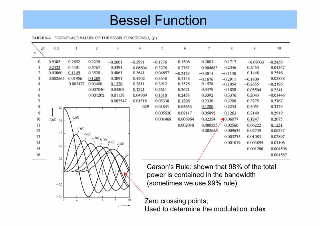
Bessel Function
Carson’s Rule: shown that 98% of the total power is contained in the bandwidth (sometimes we use 99% rule)
Zero crossing points; Used to determine the modulation index

Bessel Function for Angle Modulation • In general the modulated signal (s(t)) is
• The Bessel Function:
S(t)

Bessel Function for Angle Modulation
S(t)
S(t)

Example (A) • Assume FM modulation with modulation index of 1 • m(t) =Vmsin(2.pi.1000t) and Vc(t)= =10sin(2.pi.500.103t) • Find the following:
– Number of sets of significant side frequencies (G(f)) – Amplitude of freq. components – Draw the frequency component

Example (B) • Plot the spectrum from the modulated FM
signal for β=0.5, 1, 2
β=0.5
Normalized
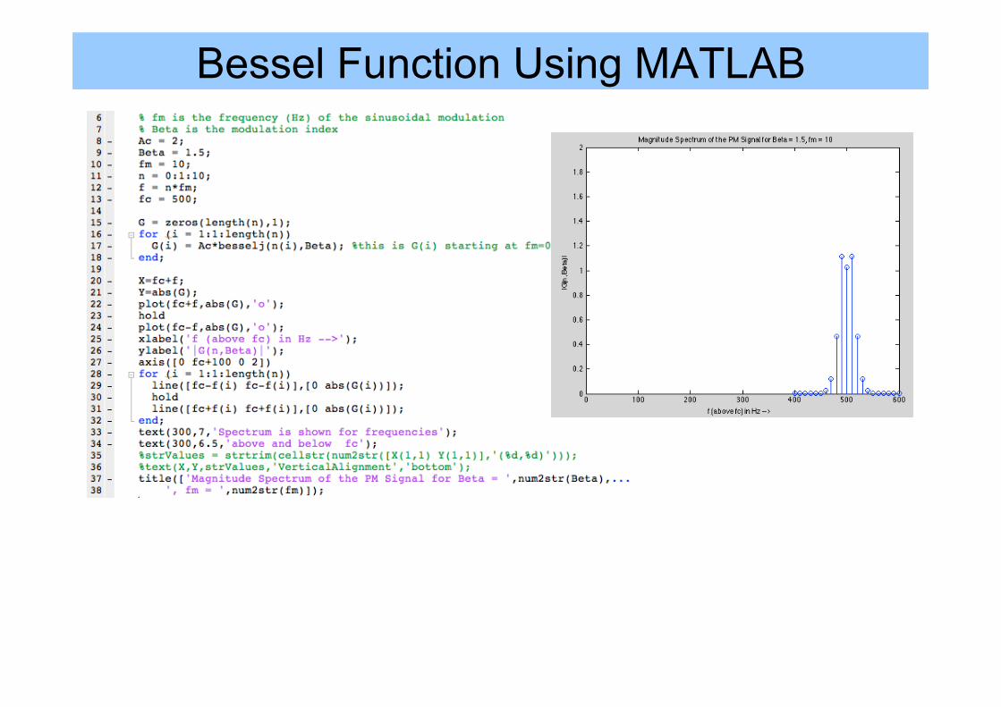
Bessel Function Using MATLAB

Narrowband Angle Modulation
Note: m=|θ(t)|

NBPM / NBFM & WB Angle Modulation
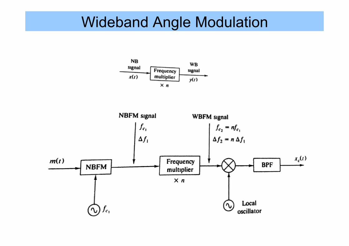
Wideband Angle Modulation
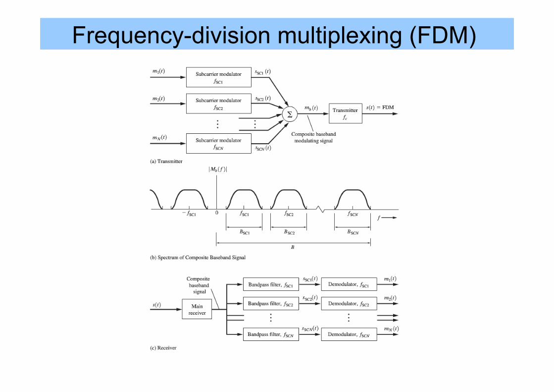
Frequency-division multiplexing (FDM)
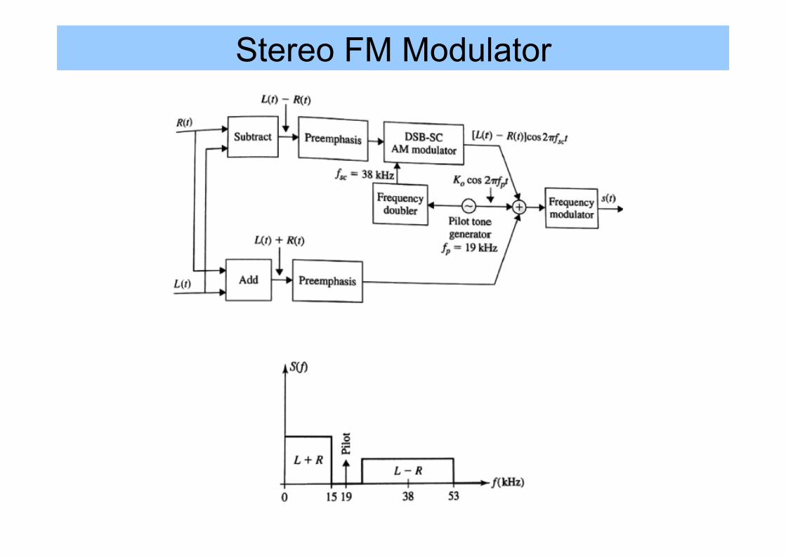
Stereo FM Modulator
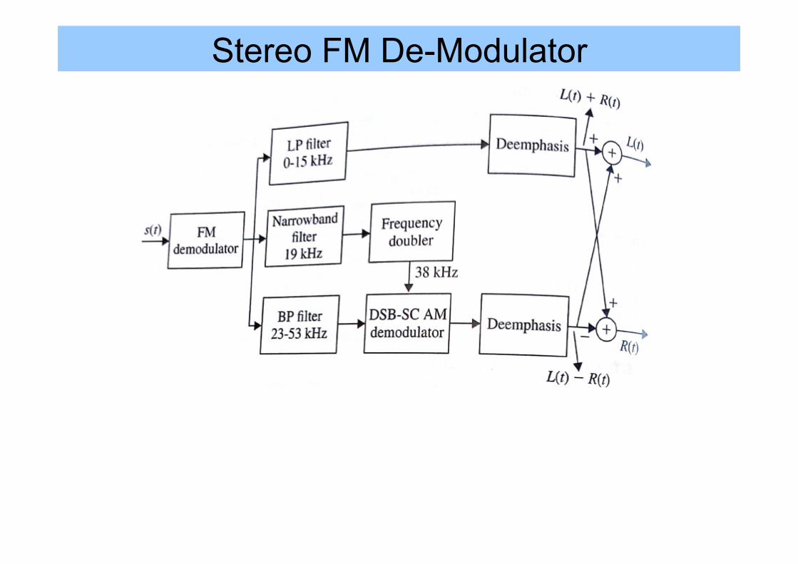
Stereo FM De-Modulator
References • Leon W. Couch II, Digital and Analog Communication
Systems, 8th edition, Pearson / Prentice, Chapter 5 • Electronic Communications System: Fundamentals Through
Advanced, Fifth Edition by Wayne Tomasi – Chapter 7 (https://www.goodreads.com/book/show/209442.Electronic_Communications_System)
See Notes


![Freq [GHz]Q0Q0 R/Q [Ω]±Voltage [kV] 2.07224187862.340.22 2.08329155730.510.04 2.09903219379.724.04 3.0231018102114.01.43 3.27113743239.10.12 4.716412612713.00.02.](https://static.fdocument.org/doc/165x107/56649f355503460f94c52820/freq-ghzq0q0-rq-voltage-kv-20722418786234022-20832915573051004.jpg)