Crystal Structures of 11β-Hydroxysteroid Dehydrogenase Type 1
Chapter 3-
SUBJECTS
• Crystal Systems
• Crystallographic points, directions, and planes
• Linear and planar densities
1
CHAPTER 3_2: CRYSTAL
STRUCTURES & PROPERTIES
• X-ray diffraction
Chapter 3-
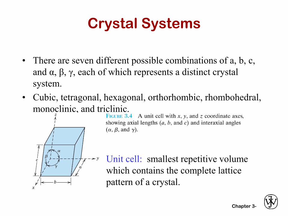
Crystal Systems
• There are seven different possible combinations of a, b, c,
and α, β, γ, each of which represents a distinct crystal
system.
• Cubic, tetragonal, hexagonal, orthorhombic, rhombohedral,
monoclinic, and triclinic.
Unit cell: smallest repetitive volume
which contains the complete lattice
pattern of a crystal.
Chapter 3- 2
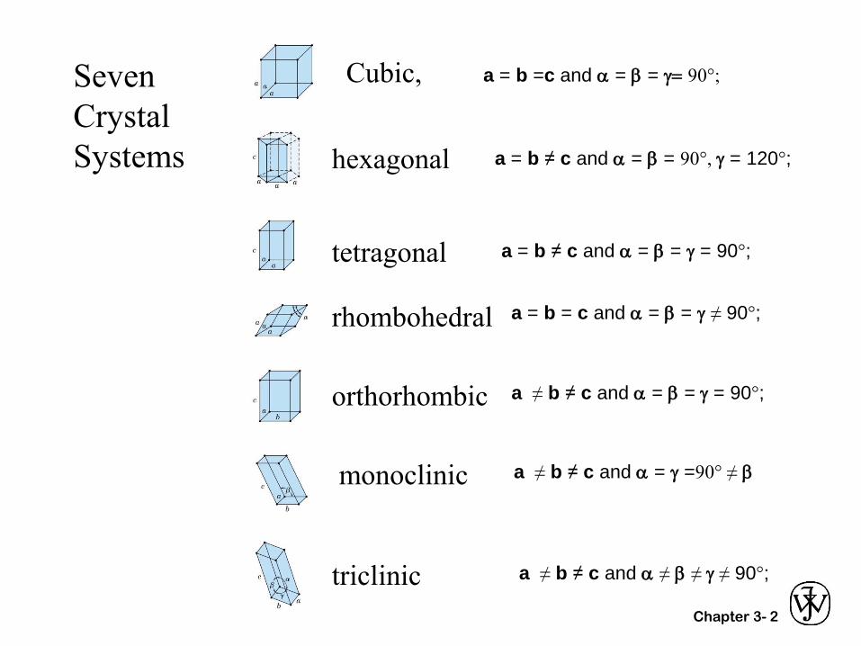
Seven
Crystal
Systems
Cubic,
hexagonal
triclinic
monoclinic
orthorhombic
rhombohedral
tetragonal
a = b ≠ c and a = b = 90°, g = 120°;
a = b ≠ c and a = b = g = 90°;
a = b = c and a = b = g ≠ 90°;
a ≠ b ≠ c and a = b = g = 90°;
a ≠ b ≠ c and a = g =90° ≠ b
a ≠ b ≠ c and a ≠ b ≠ g ≠ 90°;
a = b =c and a = b = g= 90°;
Chapter 3-
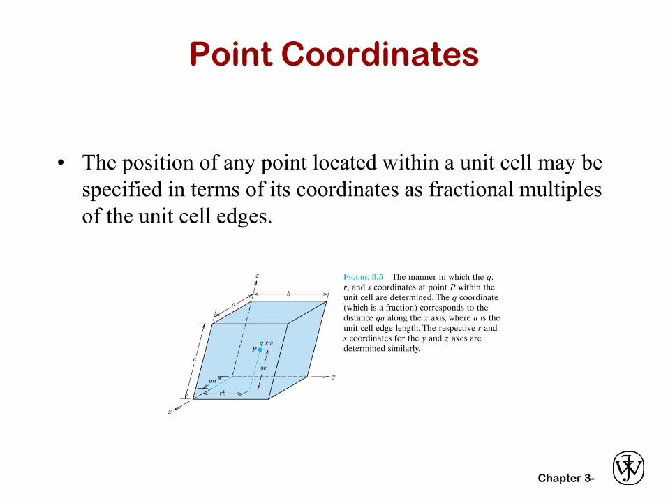
Point Coordinates
• The position of any point located within a unit cell may be
specified in terms of its coordinates as fractional multiples
of the unit cell edges.
Chapter 3-
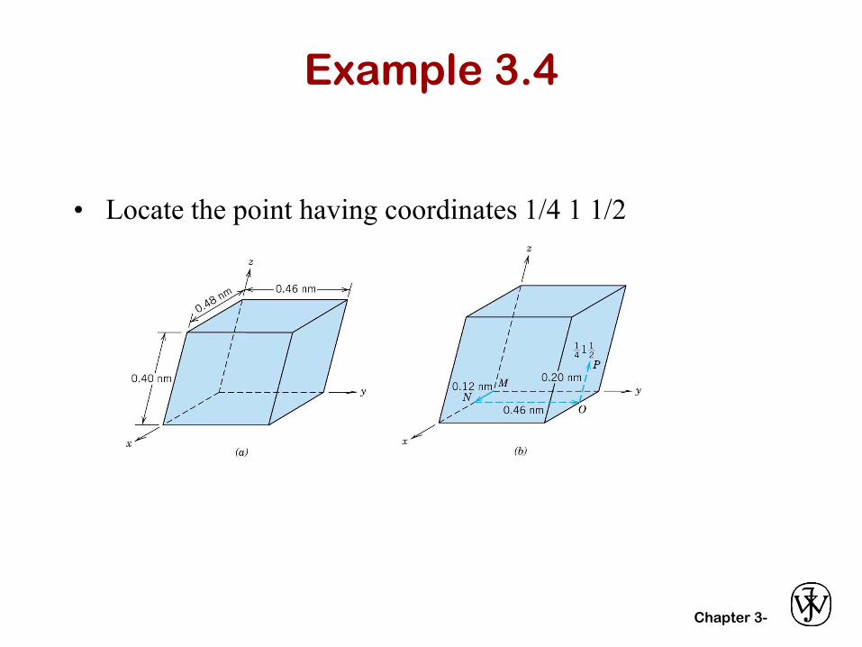
Example 3.4
• Locate the point having coordinates 1/4 1 1/2
Chapter 3-
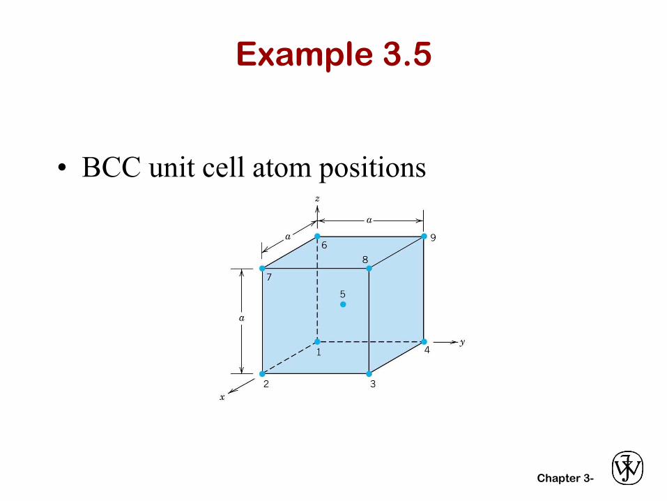
Example 3.5
• BCC unit cell atom positions
Chapter 3-
Crystallographic Directions
• The length of the vector projection on each of the three
axes is determined; these are measured in terms of the unit
cell dimensions.
• These three numbers are reduced to the smallest integer
values by multiplying or dividing by a common factor.
• The three indices are represented as [uvw].
Chapter 3-
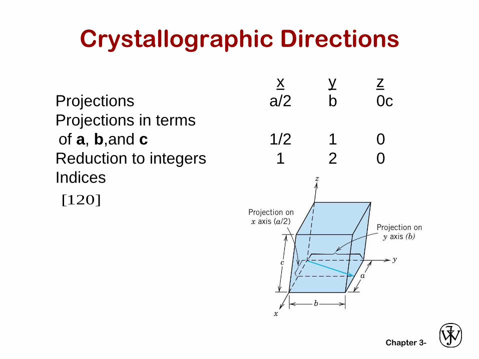
Crystallographic Directions
x y z
Projections a/2 b 0c
Projections in terms
of a, b,and c 1/2 1 0
Reduction to integers 1 2 0
Indices
[120]
Chapter 3-
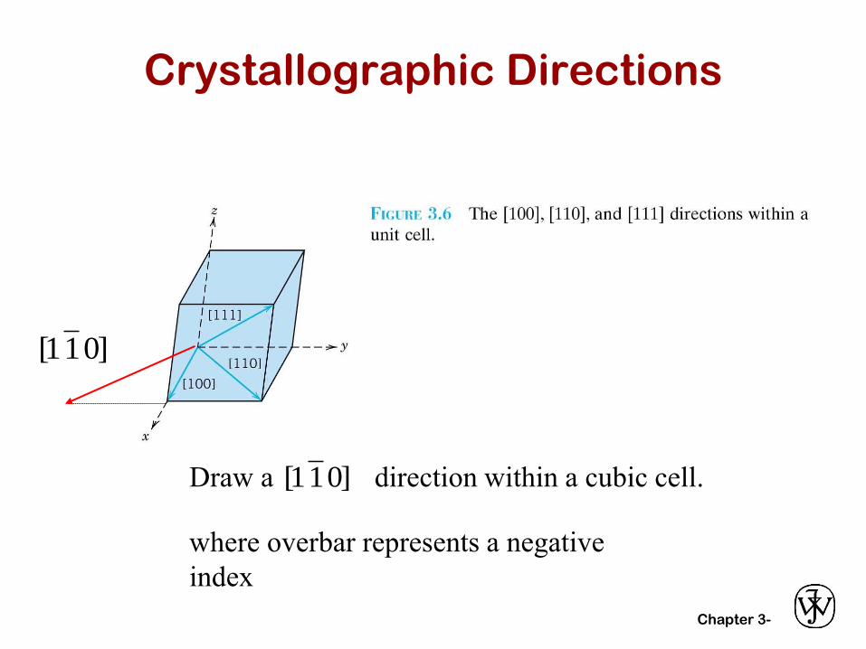
Crystallographic Directions
Draw a direction within a cubic cell.]011[
]011[
where overbar represents a negative
index
Chapter 3-
Crystallographic Planes
• Crystallographic planes are specified by three
Miller indices as (hkl).
• Procedure:
– The length of the planar intercept for each axis is
determined in terms of the lattice parameters, a,b,c.
– The reciprocal of these numbers are taken.
– These three numbers are changed to the set of smallest
integers by a common factor.
– The indices are represented by (hkl).
Chapter 3-
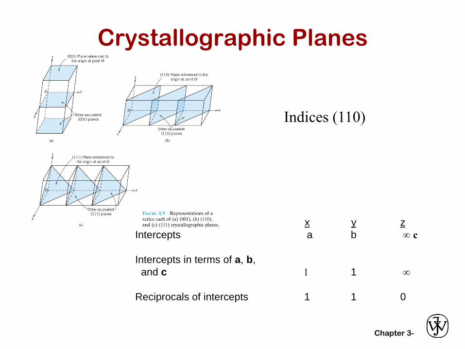
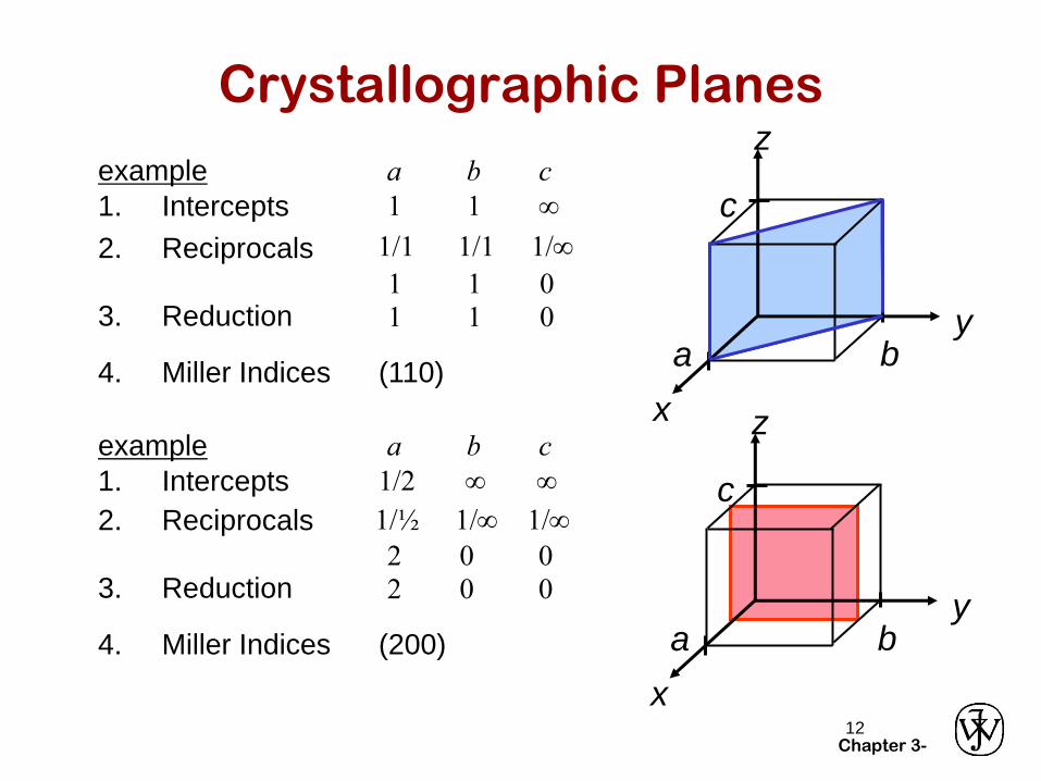
Crystallographic Planes
x y z
Intercepts a b c
Intercepts in terms of a, b,
and c 1 1
Reciprocals of intercepts 1 1 0
Indices (110)
Chapter 3-12
Crystallographic Planesz
x
ya b
c
4. Miller Indices (110)
example a b cz
x
ya b
c
4. Miller Indices (200)
1. Intercepts 1 1
2. Reciprocals 1/1 1/1 1/
1 1 03. Reduction 1 1 0
1. Intercepts 1/2
2. Reciprocals 1/½ 1/ 1/
2 0 03. Reduction 2 0 0
example a b c
Chapter 3-13
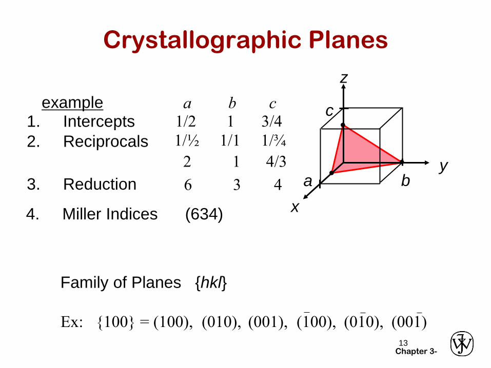
Crystallographic Planes
z
x
ya b
c•
••
4. Miller Indices (634)
example1. Intercepts 1/2 1 3/4
a b c
2. Reciprocals 1/½ 1/1 1/¾
2 1 4/3
3. Reduction 6 3 4
(001)(010),
Family of Planes {hkl}
(100), (010),(001),Ex: {100} = (100),
Chapter 3-
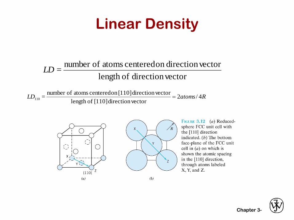
Linear Density
vectordirection oflength
vectordirection on centered atoms ofnumber =LD
RatomsLD 4/2vectordirection [110] oflength
vectordirection [110]on centered atoms ofnumber = 110 =
Chapter 3-
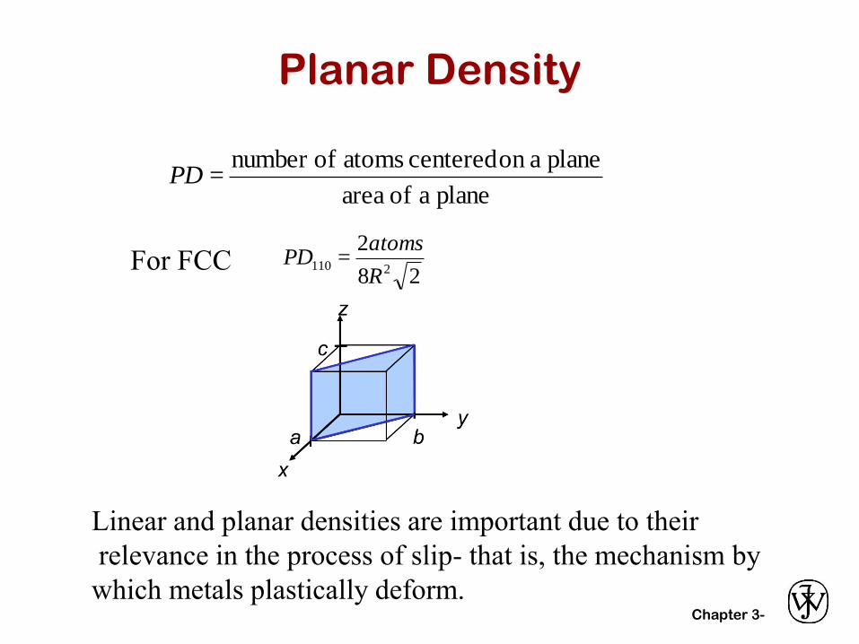
Planar Density
plane a of area
plane aon centered atoms ofnumber =PD
28
2 =
2110R
atomsPD
Linear and planar densities are important due to their
relevance in the process of slip- that is, the mechanism by
which metals plastically deform.
For FCC
Chapter 3-16
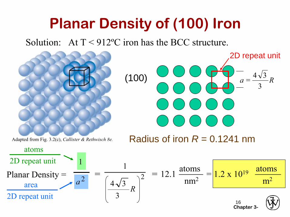
Planar Density of (100) Iron
Solution: At T < 912ºC iron has the BCC structure.
(100)
Radius of iron R = 0.1241 nm
R3
34a =
Adapted from Fig. 3.2(c), Callister & Rethwisch 8e.
2D repeat unit
= Planar Density =a 2
1
atoms
2D repeat unit
= nm2
atoms12.1
m2
atoms= 1.2 x 10¹⁹
1
2
R3
34area
2D repeat unit
Chapter 3-18
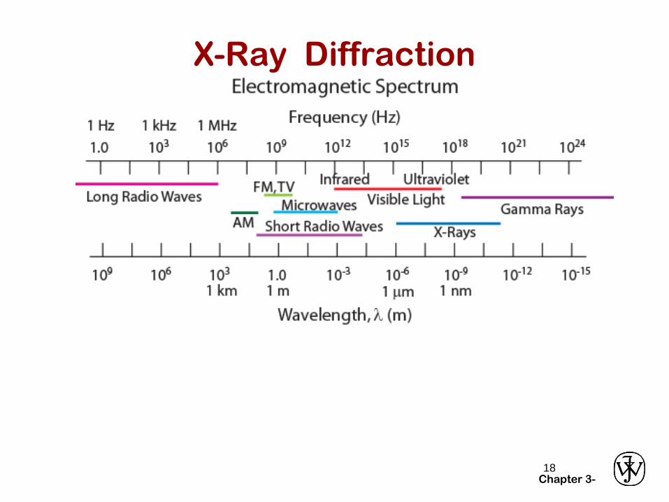
X-Ray Diffraction
Chapter 3-19
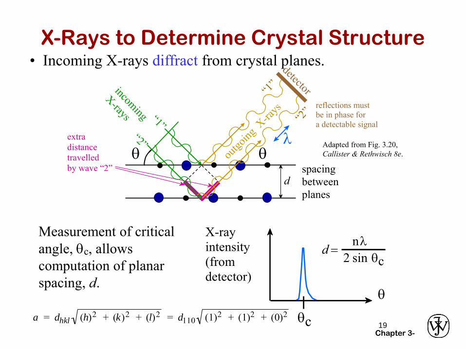
X-Rays to Determine Crystal Structure
X-ray
intensity
(from
detector)
q
qc
d =nl
2 sin qc
Measurement of critical
angle, qc, allows
computation of planar
spacing, d.
• Incoming X-rays diffract from crystal planes.
Adapted from Fig. 3.20,
Callister & Rethwisch 8e.
reflections must
be in phase for
a detectable signal
spacing
between
planes
d
ql
q
extra
distance
travelled
by wave “2”
a = dhkl (h)2 + (k)2 + (l)2 = d110 (1)2 + (1)2 + (0)2
Chapter 3-20
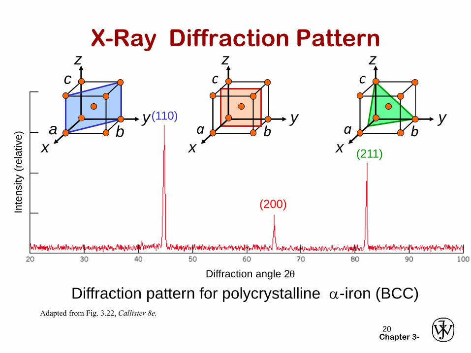
X-Ray Diffraction Pattern
Adapted from Fig. 3.22, Callister 8e.
(110)
(200)
(211)
z
x
ya b
c
Diffraction angle 2q
Diffraction pattern for polycrystalline a-iron (BCC)
Inte
nsity (
rela
tive)
z
x
ya b
cz
x
ya b
c
Chapter 3-21
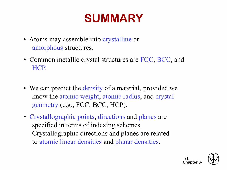
SUMMARY
• Atoms may assemble into crystalline or
amorphous structures.
• We can predict the density of a material, provided we
know the atomic weight, atomic radius, and crystal
geometry (e.g., FCC, BCC, HCP).
• Common metallic crystal structures are FCC, BCC, and
HCP.
• Crystallographic points, directions and planes are
specified in terms of indexing schemes.
Crystallographic directions and planes are related
to atomic linear densities and planar densities.
Chapter 3-22
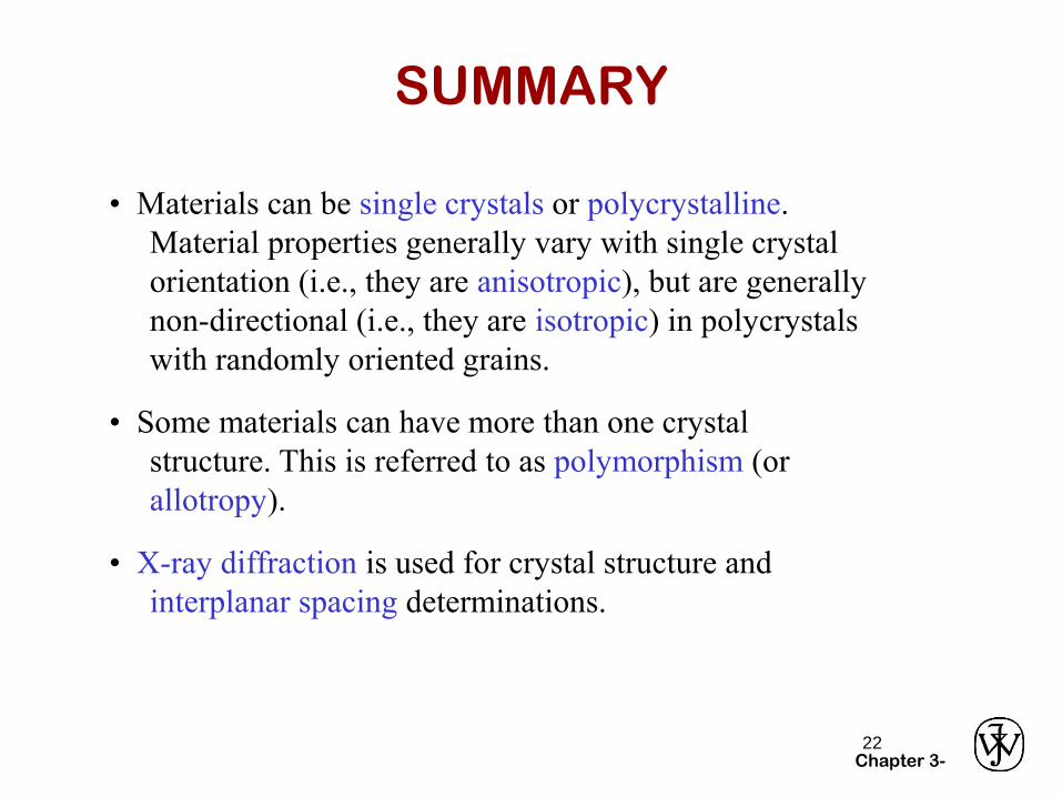
• Some materials can have more than one crystal
structure. This is referred to as polymorphism (or
allotropy).
SUMMARY
• Materials can be single crystals or polycrystalline.
Material properties generally vary with single crystal
orientation (i.e., they are anisotropic), but are generally
non-directional (i.e., they are isotropic) in polycrystals
with randomly oriented grains.
• X-ray diffraction is used for crystal structure and
interplanar spacing determinations.
Chapter 3-
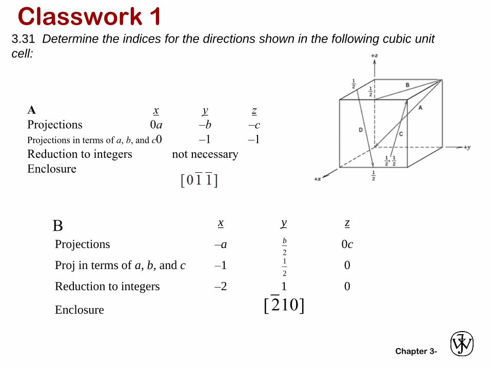
Classwork 13.31 Determine the indices for the directions shown in the following cubic unit
cell:
A x y z
Projections 0a –b –c
Projections in terms of a, b, and c0 –1 –1
Reduction to integers not necessary
Enclosure
x y z
Projections –a
b
2 0c
Proj in terms of a, b, and c –1
1
2 0
Reduction to integers –2 1 0
Enclosure
[2 10]
B
Chapter 3-
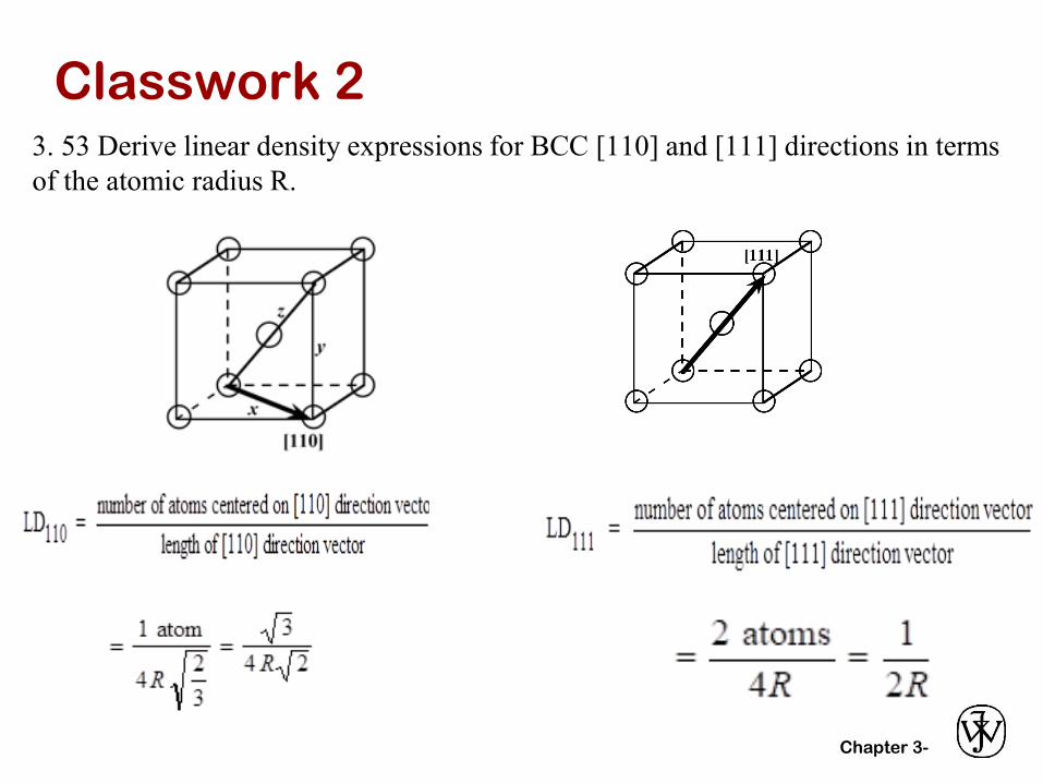
Classwork 23. 53 Derive linear density expressions for BCC [110] and [111] directions in terms
of the atomic radius R.
Chapter 3-
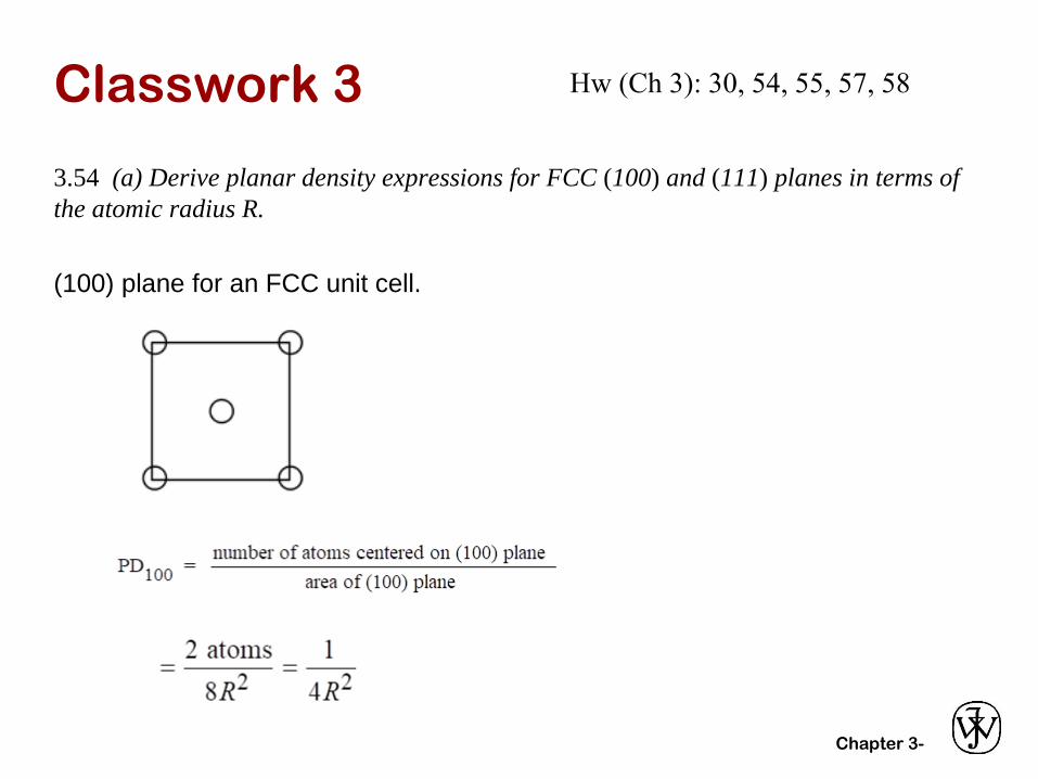
Classwork 3
3.54 (a) Derive planar density expressions for FCC (100) and (111) planes in terms of
the atomic radius R.
(100) plane for an FCC unit cell.
Hw (Ch 3): 30, 54, 55, 57, 58