Chapter 21 Faraday’s Law of Electromagnetic Inductionstrauss/phys1215/Chap21.pdfFaraday’s Law...
85
Chapter 21 Faraday’s Law of Electromagnetic Induction
Transcript of Chapter 21 Faraday’s Law of Electromagnetic Inductionstrauss/phys1215/Chap21.pdfFaraday’s Law...
Chapter 21
Faraday’s Law of Electromagnetic Induction
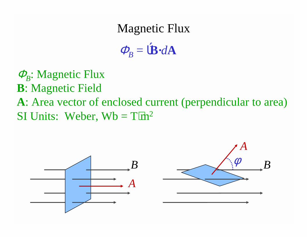
ΦB: Magnetic FluxB: Magnetic FieldA: Area vector of enclosed current (perpendicular to area)SI Units: Weber, Wb = T⋅m2
Magnetic Flux
ΦB = ÚB·dA
B
A
A
Bφ
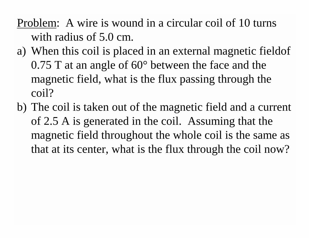
Problem: A wire is wound in a circular coil of 10 turns with radius of 5.0 cm.
a) When this coil is placed in an external magnetic fieldof0.75 T at an angle of 60° between the face and the magnetic field, what is the flux passing through the coil?
b) The coil is taken out of the magnetic field and a current of 2.5 A is generated in the coil. Assuming that the magnetic field throughout the whole coil is the same as that at its center, what is the flux through the coil now?
A changing magnetic flux induces an emf (voltage difference).
1. How do you change it?2. What are the consequences of the induced emf?
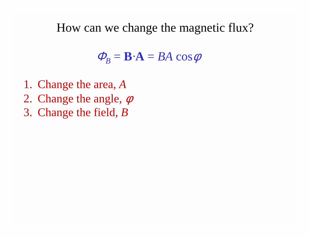
How can we change the magnetic flux?
ΦB = B·A = BA cosφ
1. Change the area, A2. Change the angle, φ3. Change the field, B
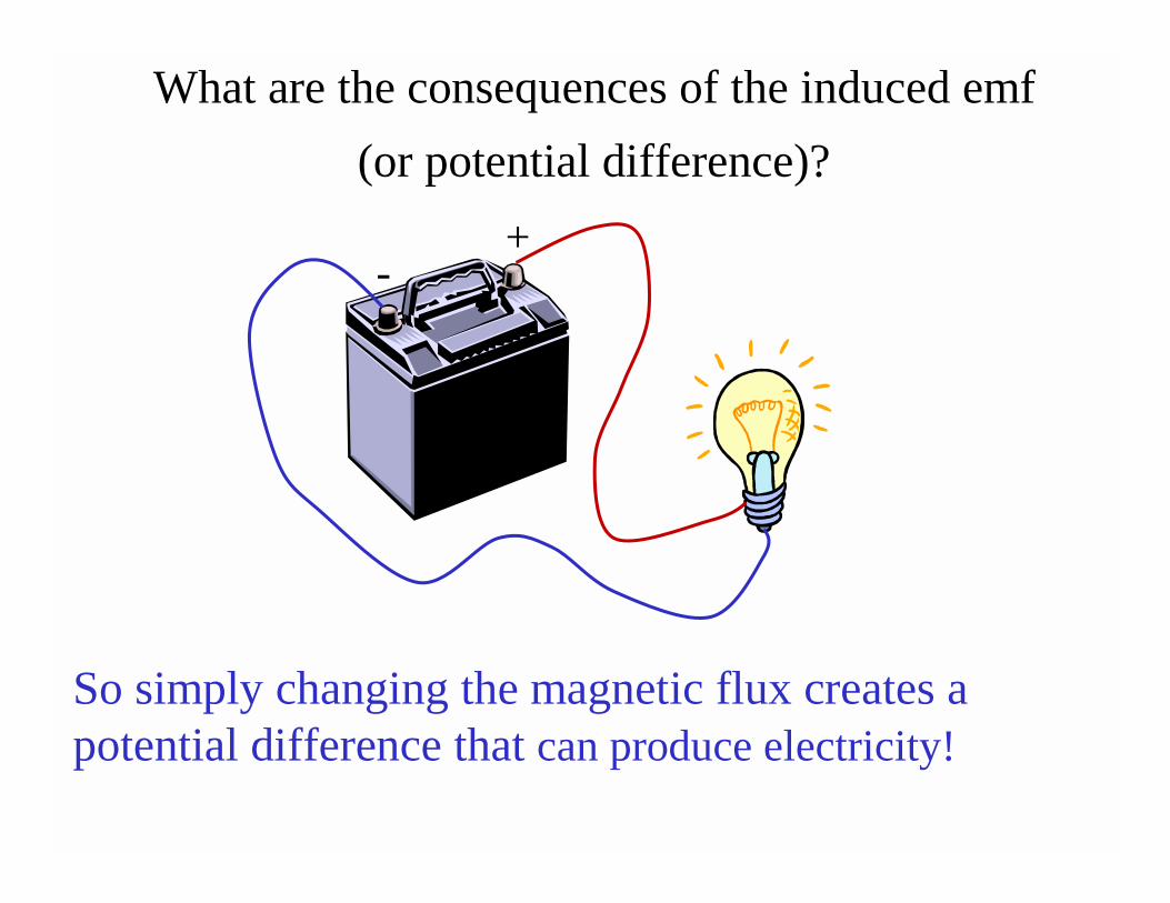
What are the consequences of the induced emf
(or potential difference)?
+-
So simply changing the magnetic flux creates a potential difference that can produce electricity!
Faraday’s Law gives the magnitude of the induced emf
E: The induced potential differencedΦB/dt is the changing magnetic flux in a certain time−: A reminder to use Lenz’s law
Lenz’s Law gives the direction of the induced emfThe induced emf always acts to oppose the
changing magnetic flux.
E = − dΦB/dt
Three steps to solving problems with Lenz’s law.
1. Determine the direction of the external magnetic field (B), inside the designated area (often a loop of wire).
2. Determine if the flux (Φ) is increasing or decreasing inside the designated area. (Look at how B, A, and cosφare changing).
3. Choose the current direction to create an inducedmagnetic field (BI) that opposes the change in Φ. If flux is decreasing choose current to increase B. If flux is increasing, choose current to decrease B.
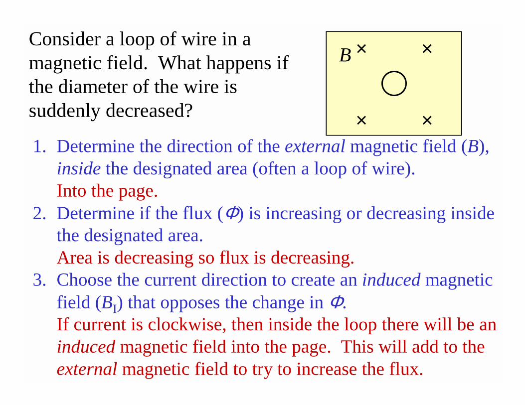
1. Determine the direction of the external magnetic field (B), inside the designated area (often a loop of wire).Into the page.
2. Determine if the flux (Φ) is increasing or decreasing inside the designated area. Area is decreasing so flux is decreasing.
3. Choose the current direction to create an induced magnetic field (BI) that opposes the change in Φ. If current is clockwise, then inside the loop there will be an induced magnetic field into the page. This will add to the external magnetic field to try to increase the flux.
Consider a loop of wire in a magnetic field. What happens if the diameter of the wire is suddenly decreased?
× ×
× ×
B × ×
× ×
B
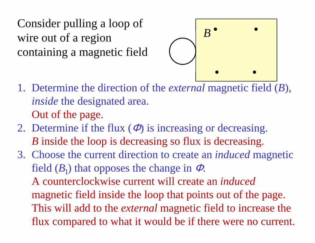
1. Determine the direction of the external magnetic field (B), inside the designated area.Out of the page.
2. Determine if the flux (Φ) is increasing or decreasing. B inside the loop is decreasing so flux is decreasing.
3. Choose the current direction to create an induced magnetic field (BI) that opposes the change in Φ. A counterclockwise current will create an inducedmagnetic field inside the loop that points out of the page. This will add to the external magnetic field to increase the flux compared to what it would be if there were no current.
Consider pulling a loop of wire out of a region containing a magnetic field
• •
• •
B • •
• •
B • •
• •
B
We must reduce the flux. To do this we should create an induced magnetic field that points out of the page so it will subtract from the external magnetic field that points into the page. A counterclockwise current will create such a field.
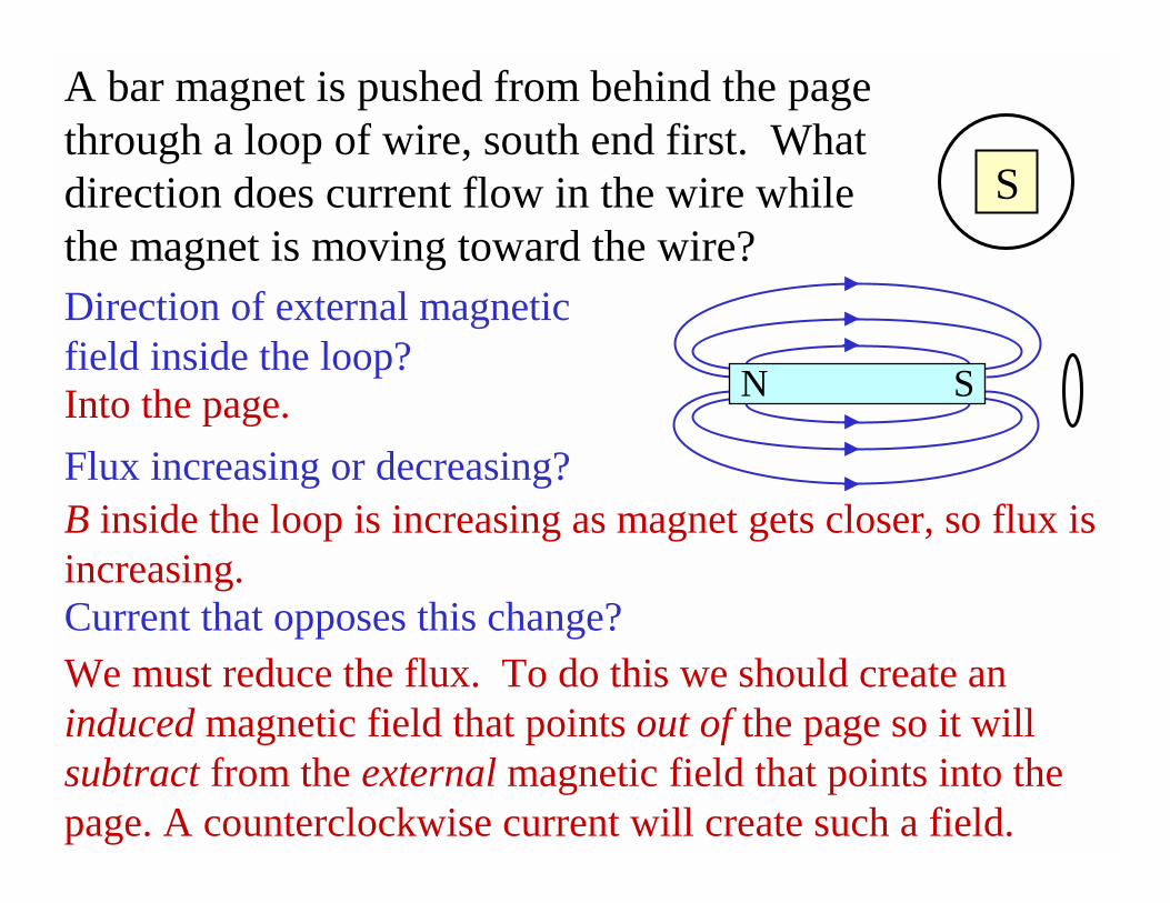
A bar magnet is pushed from behind the page through a loop of wire, south end first. What direction does current flow in the wire while the magnet is moving toward the wire?
S
Direction of external magnetic field inside the loop?Into the page.
Flux increasing or decreasing?
B inside the loop is increasing as magnet gets closer, so flux isincreasing.Current that opposes this change?
N S
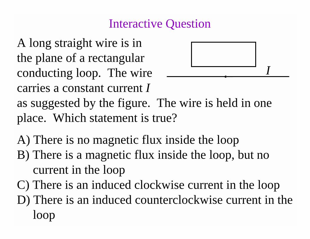
A long straight wire is in the plane of a rectangular conducting loop. The wire carries a constant current Ias suggested by the figure. The wire is held in one place. Which statement is true?
A) There is no magnetic flux inside the loopB) There is a magnetic flux inside the loop, but no
current in the loopC) There is an induced clockwise current in the loopD) There is an induced counterclockwise current in the
loop
I
Interactive Question
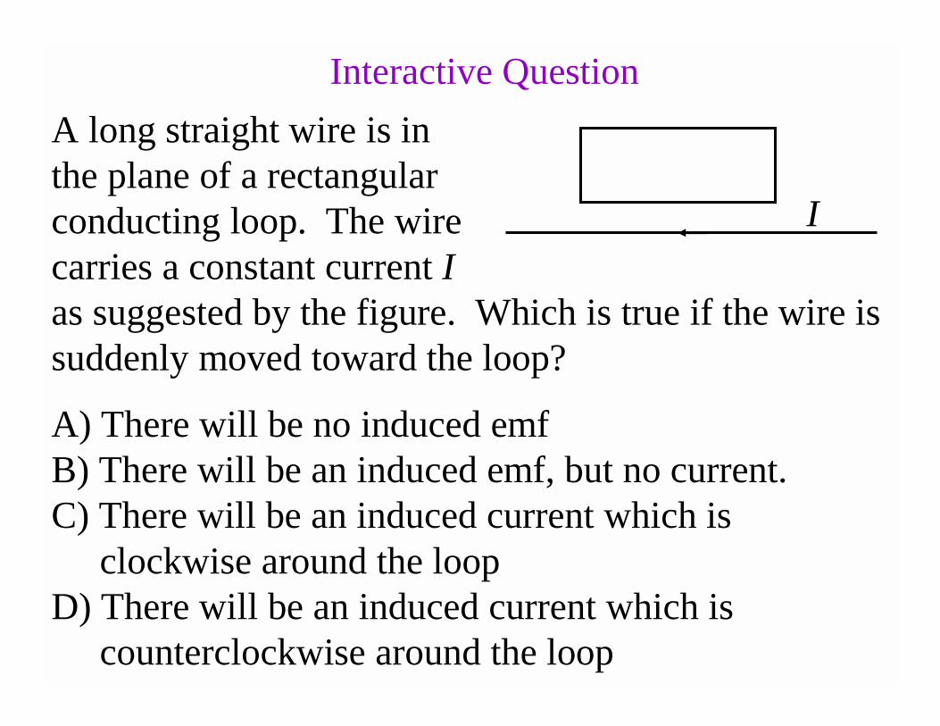
A long straight wire is in the plane of a rectangular conducting loop. The wire carries a constant current Ias suggested by the figure. Which is true if the wire is suddenly moved toward the loop?
A) There will be no induced emfB) There will be an induced emf, but no current.C) There will be an induced current which is
clockwise around the loopD) There will be an induced current which is
counterclockwise around the loop
I
Interactive Question
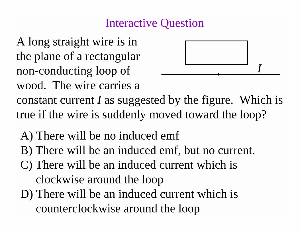
A long straight wire is in the plane of a rectangular non-conducting loop of wood. The wire carries a constant current I as suggested by the figure. Which is true if the wire is suddenly moved toward the loop?
A) There will be no induced emfB) There will be an induced emf, but no current.C) There will be an induced current which is
clockwise around the loopD) There will be an induced current which is
counterclockwise around the loop
Interactive Question
I
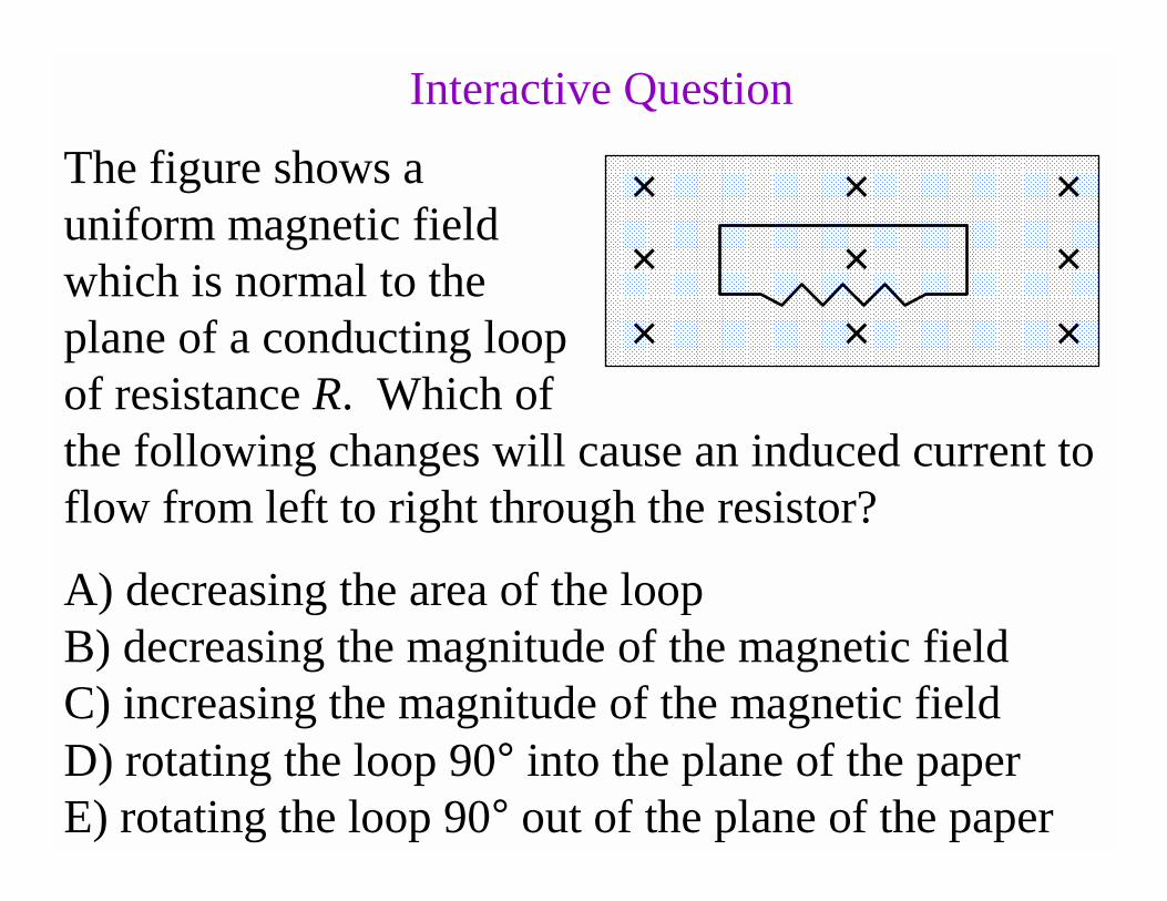
The figure shows a uniform magnetic field which is normal to the plane of a conducting loop of resistance R. Which of the following changes will cause an induced current to flow from left to right through the resistor?
× × ×× × ×× × ×
A) decreasing the area of the loopB) decreasing the magnitude of the magnetic fieldC) increasing the magnitude of the magnetic fieldD) rotating the loop 90° into the plane of the paperE) rotating the loop 90° out of the plane of the paper
Interactive Question
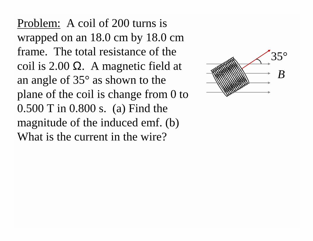
Problem: A coil of 200 turns is wrapped on an 18.0 cm by 18.0 cm frame. The total resistance of the coil is 2.00 Ω. A magnetic field at an angle of 35° as shown to the plane of the coil is change from 0 to 0.500 T in 0.800 s. (a) Find the magnitude of the induced emf. (b) What is the current in the wire?
B
35°
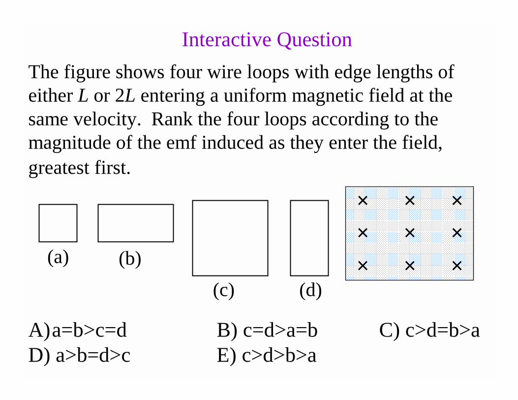
The figure shows four wire loops with edge lengths of either L or 2L entering a uniform magnetic field at the same velocity. Rank the four loops according to the magnitude of the emf induced as they enter the field,
greatest first.
× × ×× × ×× × ×
A)a=b>c=d B) c=d>a=b C) c>d=b>aD) a>b=d>c E) c>d>b>a
Interactive Question
(a) (b)
(c) (d)
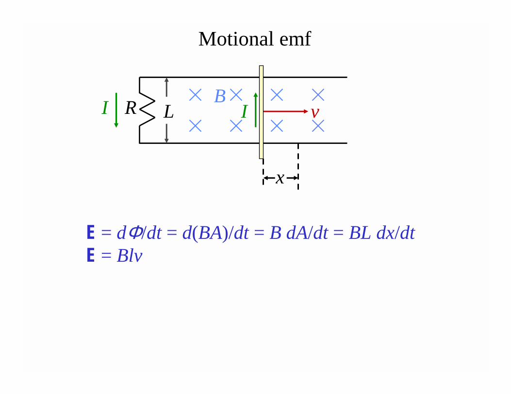
E = dΦ/dt = d(BA)/dt = B dA/dt = BL dx/dtE = Blv
v
x
R LB
Motional emf
II
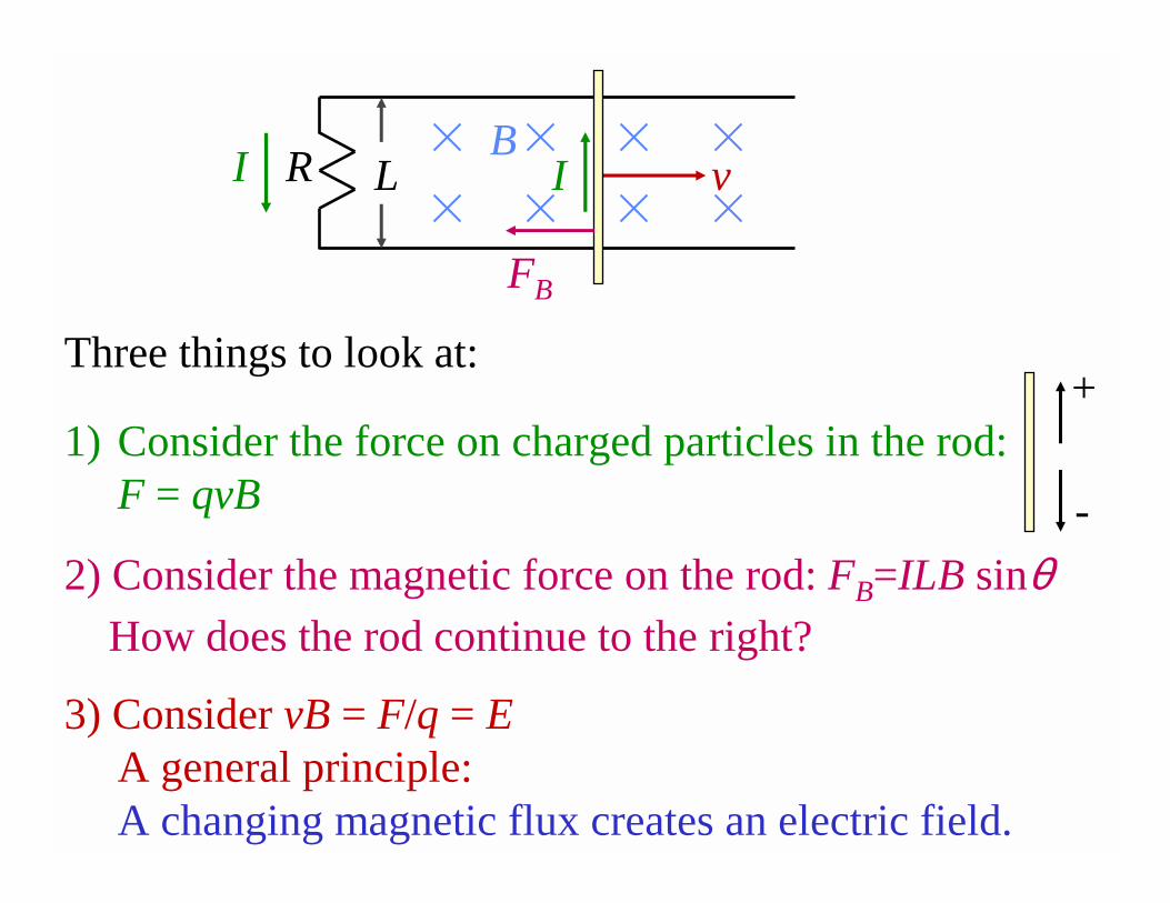
vR LB
II
FB
2) Consider the magnetic force on the rod: FB=ILB sinθ
1) Consider the force on charged particles in the rod: F = qvB
+
-
Three things to look at:
3) Consider vB = F/q = EA general principle: A changing magnetic flux creates an electric field.
How does the rod continue to the right?
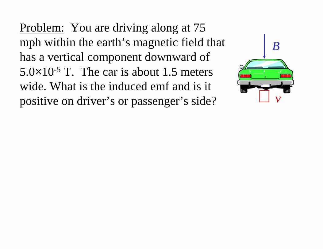
Problem: You are driving along at 75 mph within the earth’s magnetic field that has a vertical component downward of 5.0×10⁻⁵ T. The car is about 1.5 meters wide. What is the induced emf and is it positive on driver’s or passenger’s side?
B
⊗ v
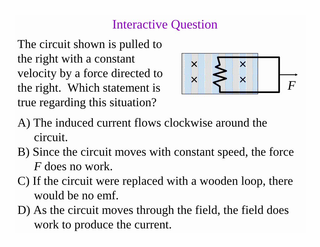
The circuit shown is pulled to the right with a constant velocity by a force directed to the right. Which statement is true regarding this situation?
× ×× × F
A) The induced current flows clockwise around the circuit.
B) Since the circuit moves with constant speed, the force F does no work.
C) If the circuit were replaced with a wooden loop, there would be no emf.
D) As the circuit moves through the field, the field does work to produce the current.
Interactive Question
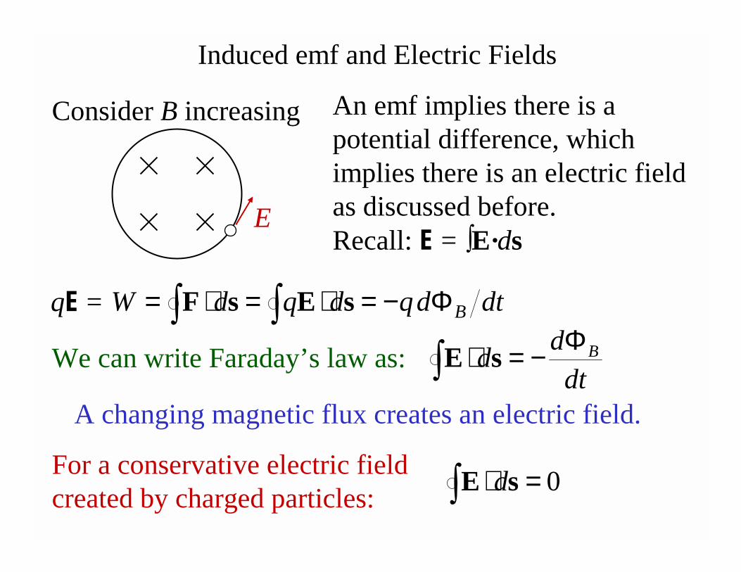
Induced emf and Electric Fields
Consider B increasing
E
An emf implies there is a potential difference, which implies there is an electric field as discussed before. Recall: E = ∫E·ds
dtdqdqdW BΦ−=⋅=⋅= ∫∫ sEsF
We can write Faraday’s law as:
A changing magnetic flux creates an electric field.
dt
dd BΦ−=⋅∫ sE
qE =
For a conservative electric field created by charged particles:
0=⋅∫ sE d
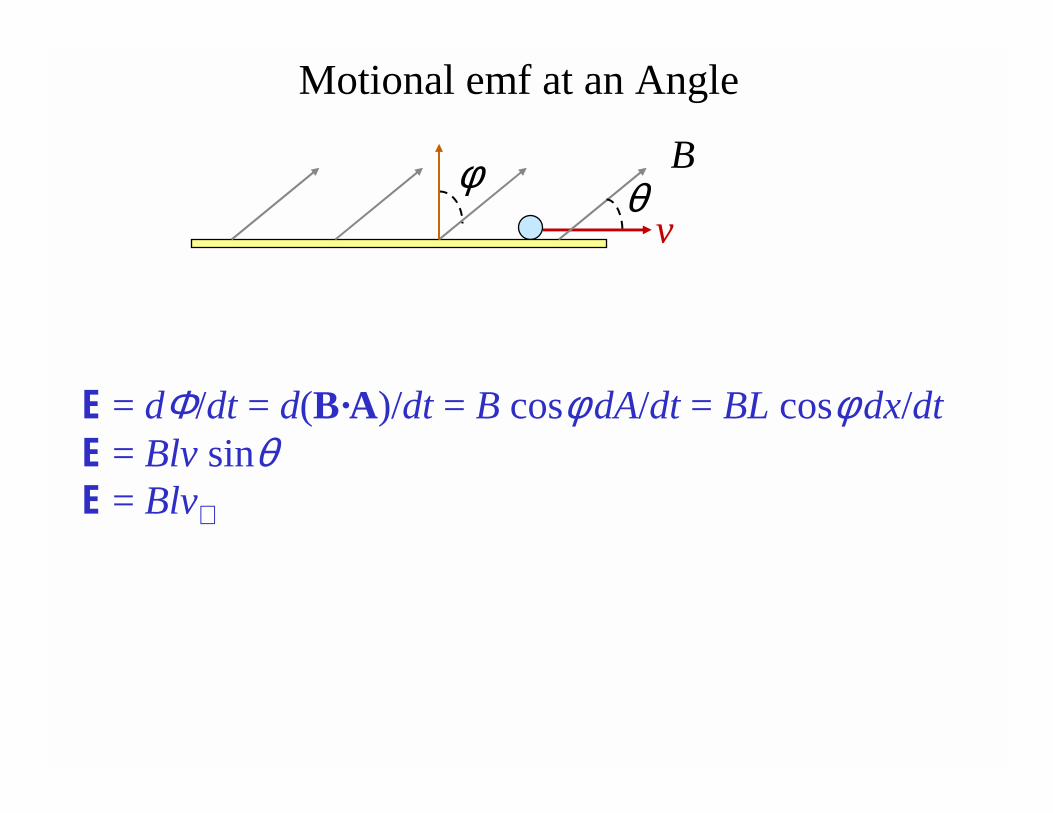
E = dΦ/dt = d(B·A)/dt = B cosφdA/dt = BL cosφdx/dtE = Blv sinθE = Blv⊥
v
Motional emf at an Angle
Bθφ
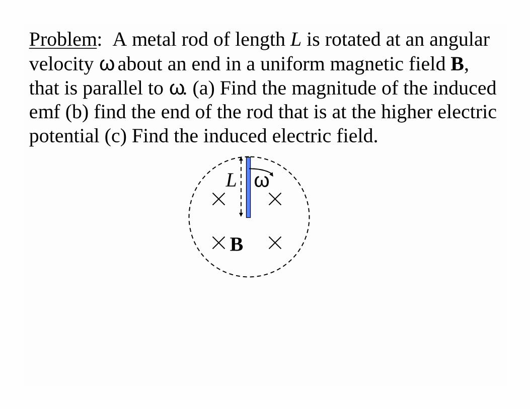
Problem: A metal rod of length L is rotated at an angular velocity ωabout an end in a uniform magnetic field B, that is parallel to ω. (a) Find the magnitude of the induced emf (b) find the end of the rod that is at the higher electric potential (c) Find the induced electric field.
B
ωL
B
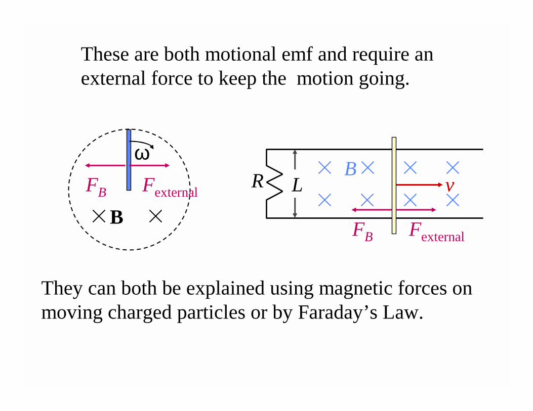
ωvR L
B
FB Fexternal
FB Fexternal
These are both motional emf and require an external force to keep the motion going.
They can both be explained using magnetic forces on moving charged particles or by Faraday’s Law.
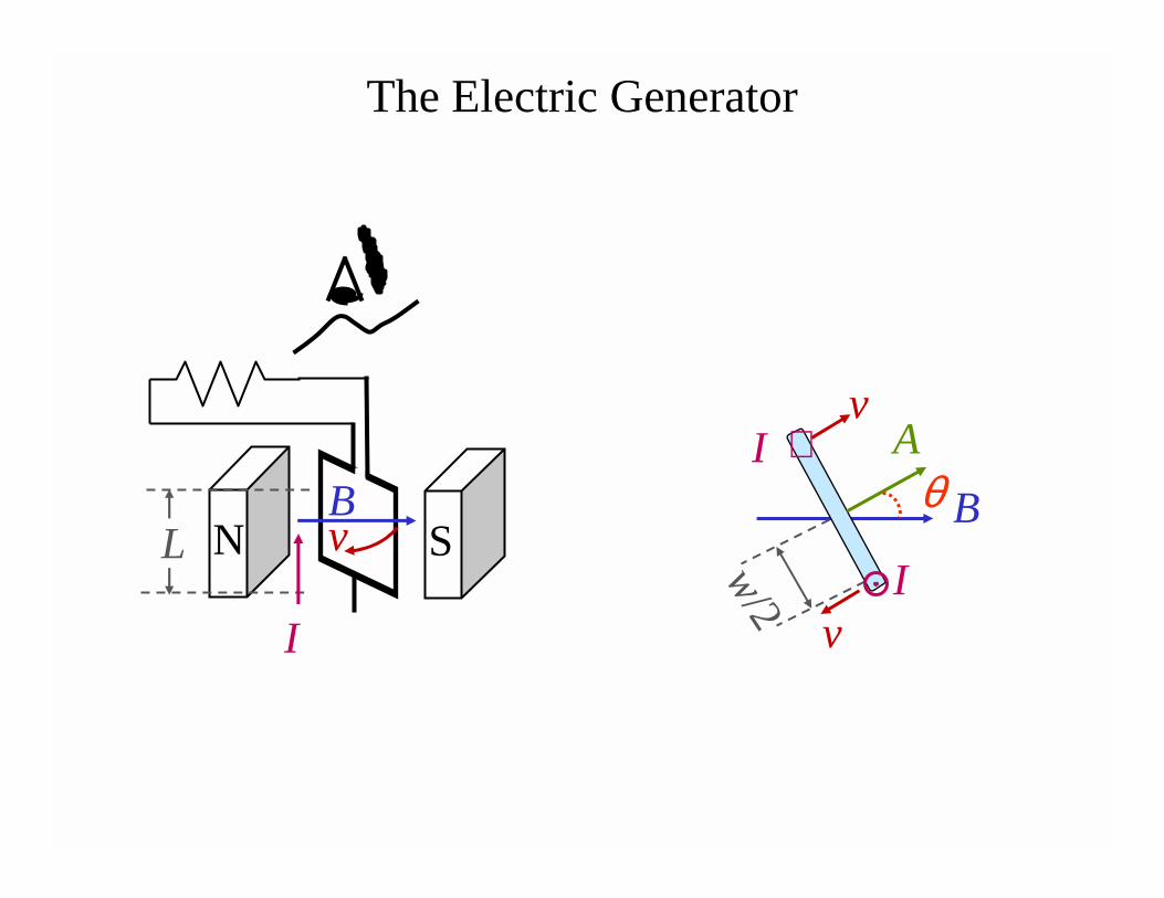
The Electric Generator
SNL v
I
vA
B
w/2
v
θ⊗
I
IB
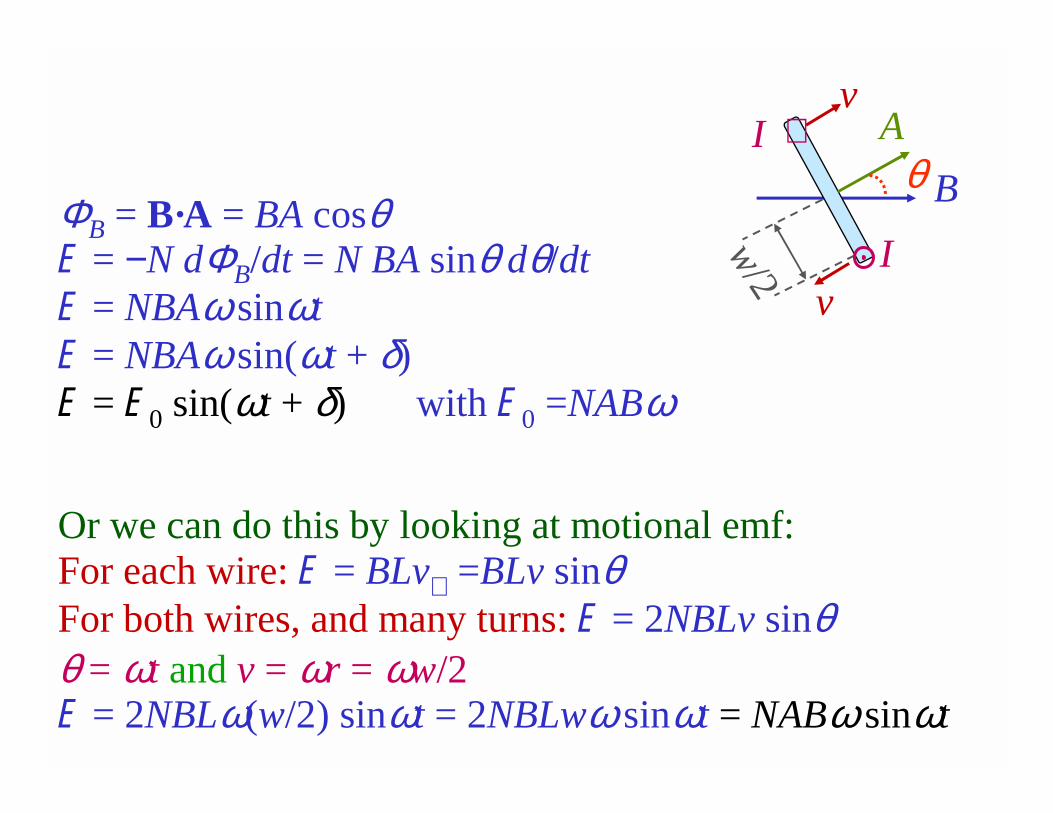
ΦB = B·A = BA cosθE = −N dΦB/dt = N BA sinθ dθ/dtE = NBAω sinωtE = NBAω sin(ωt + δ)E = E0 sin(ωt + δ) with E0 =NABω
Or we can do this by looking at motional emf:For each wire: E = BLv⊥ =BLv sinθFor both wires, and many turns: E = 2NBLv sinθθ = ωt and v = ωr = ωw/2E = 2NBLω(w/2) sinωt = 2NBLwω sinωt = NABω sinωt
vA
B
w/2
v
θ⊗
I
I
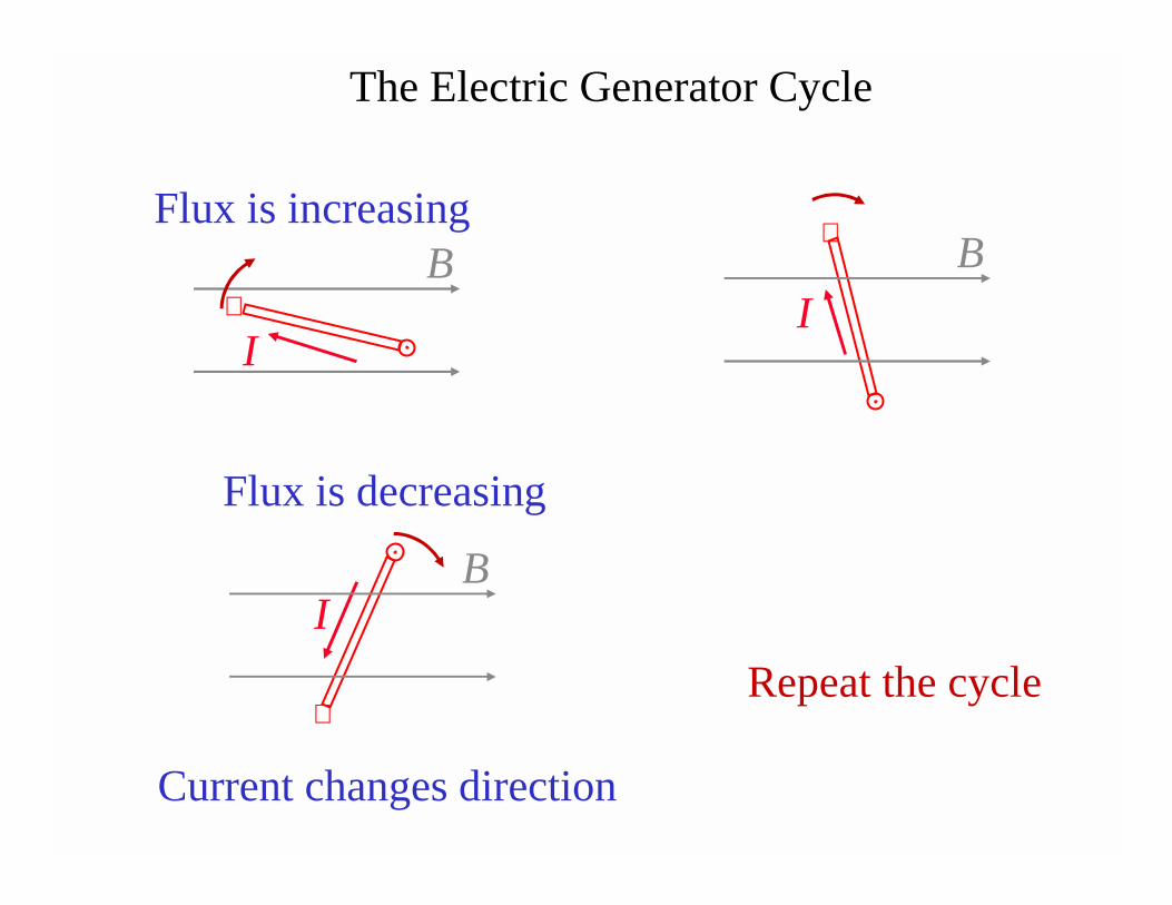
Repeat the cycle
Flux is increasing
I
B⊗
The Electric Generator Cycle
I
B⊗
IB
⊗
Flux is decreasing
Current changes direction
Notice the similarityElectric Generator: Using some mechanism, turn a loop
of wire in a magnetic field to produce a current.Electric Motor: Run a current through a loop of wire in a
magnetic field to make the loop turn.
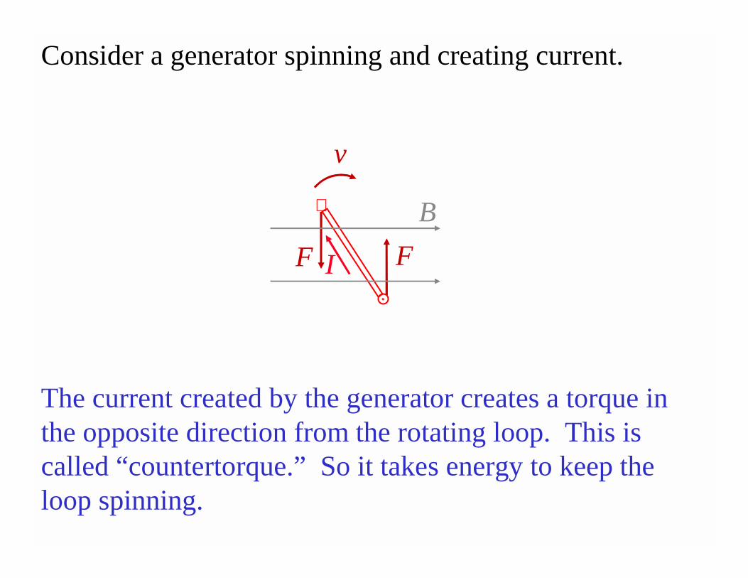
Consider a generator spinning and creating current.
FF
The current created by the generator creates a torque in the opposite direction from the rotating loop. This is called “countertorque.” So it takes energy to keep the loop spinning.
I
B⊗
v
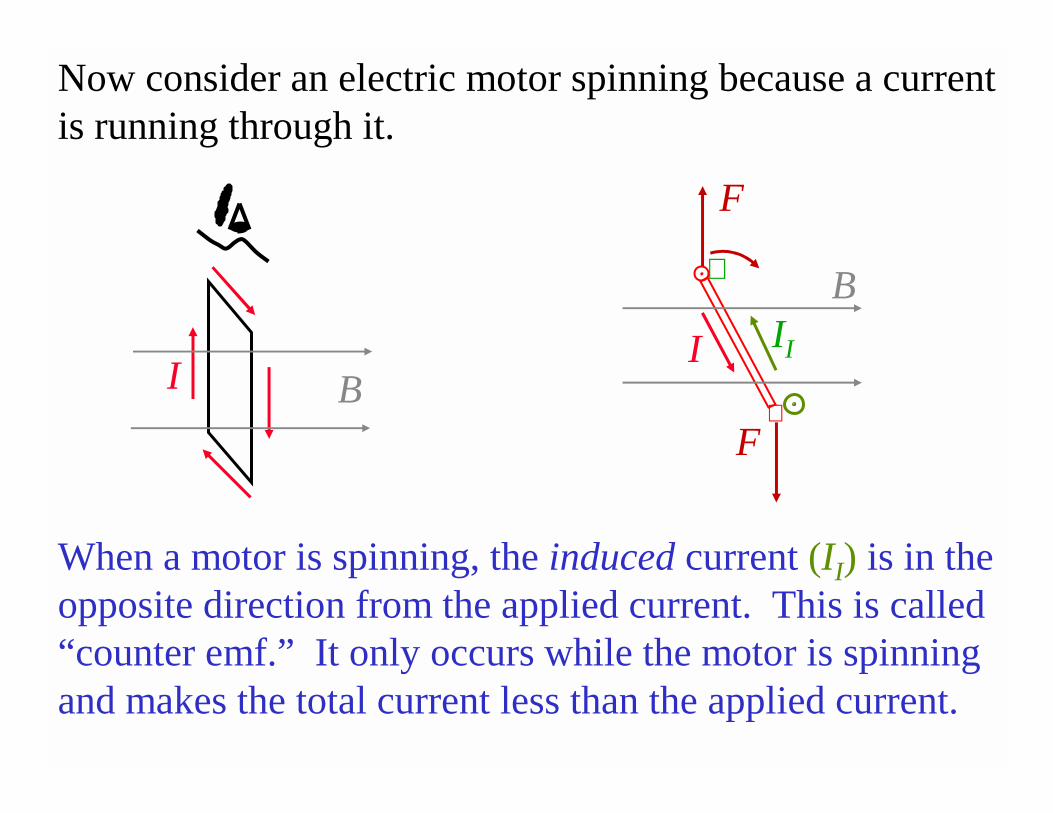
Now consider an electric motor spinning because a current is running through it.
I B
II
⊗
F
I
B
⊗F
When a motor is spinning, the induced current (II) is in the opposite direction from the applied current. This is called “counter emf.” It only occurs while the motor is spinning and makes the total current less than the applied current.
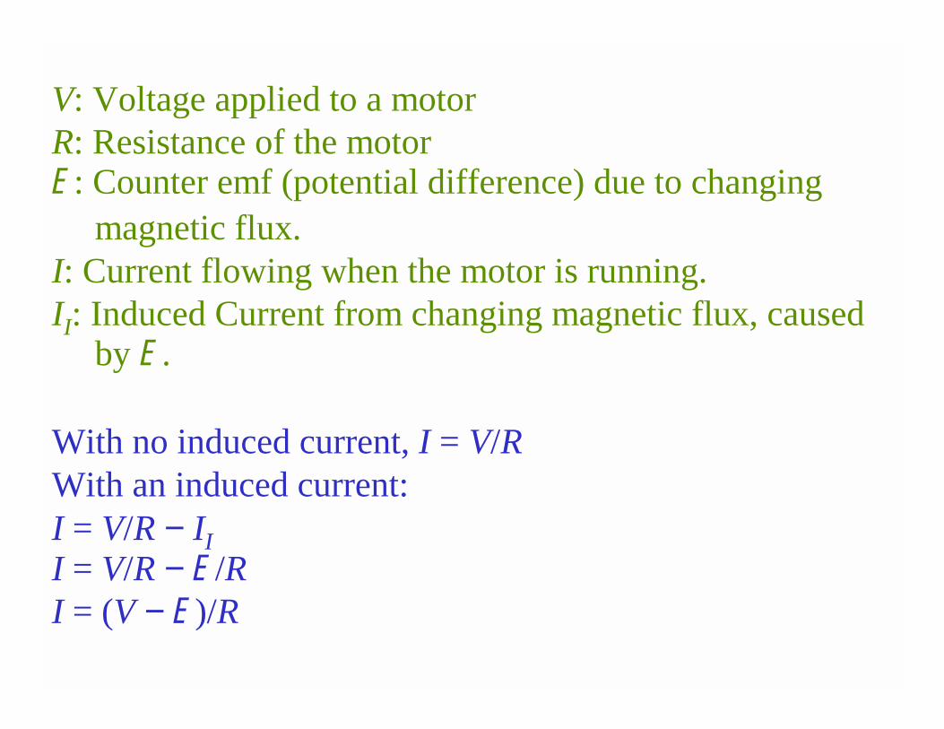
V: Voltage applied to a motorR: Resistance of the motorE: Counter emf (potential difference) due to changing
magnetic flux.I: Current flowing when the motor is running.II: Induced Current from changing magnetic flux, caused
by E.
With no induced current, I = V/RWith an induced current: I = V/R − II
I = V/R − E/RI = (V − E)/R
Problem: Suppose that a motor running at 1200 rpm has a counter emf of 50 V. What is the counter emf when the motor is running at 2000 rpm?
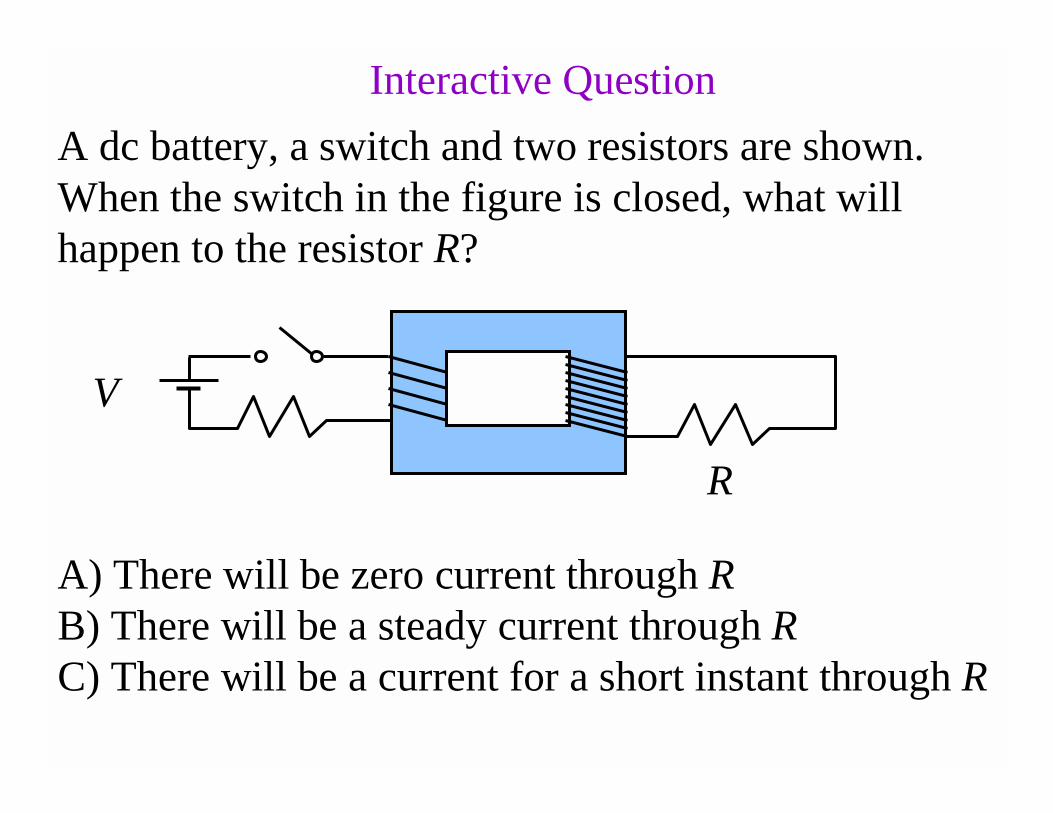
A dc battery, a switch and two resistors are shown. When the switch in the figure is closed, what will happen to the resistor R?
R
V
A) There will be zero current through RB) There will be a steady current through RC) There will be a current for a short instant through R
Interactive Question
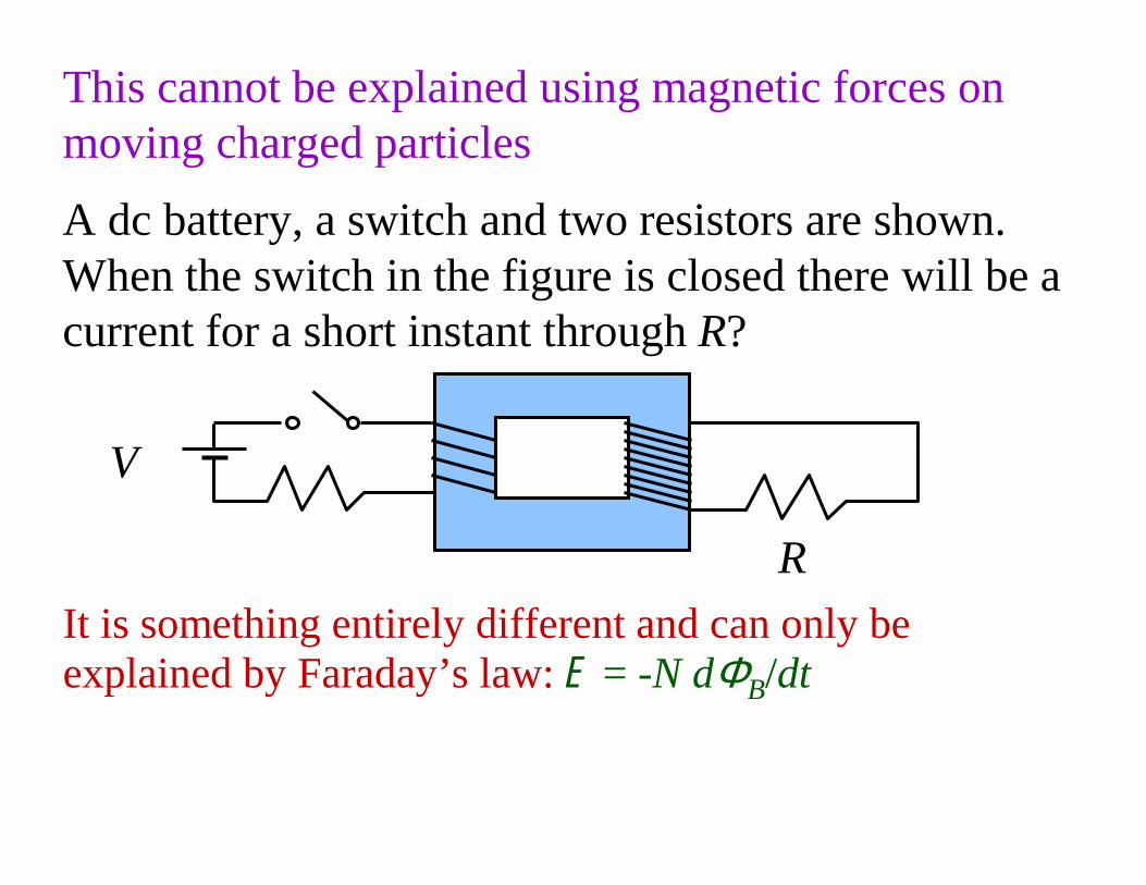
A dc battery, a switch and two resistors are shown. When the switch in the figure is closed there will be a current for a short instant through R?
R
V
This cannot be explained using magnetic forces on moving charged particles
It is something entirely different and can only be explained by Faraday’s law: E = -N dΦB/dt
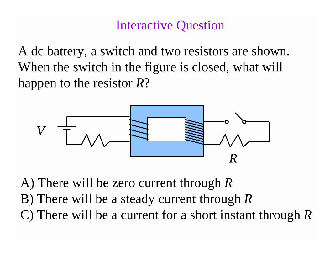
A dc battery, a switch and two resistors are shown. When the switch in the figure is closed, what will happen to the resistor R?
R
V
A) There will be zero current through RB) There will be a steady current through RC) There will be a current for a short instant through R
Interactive Question
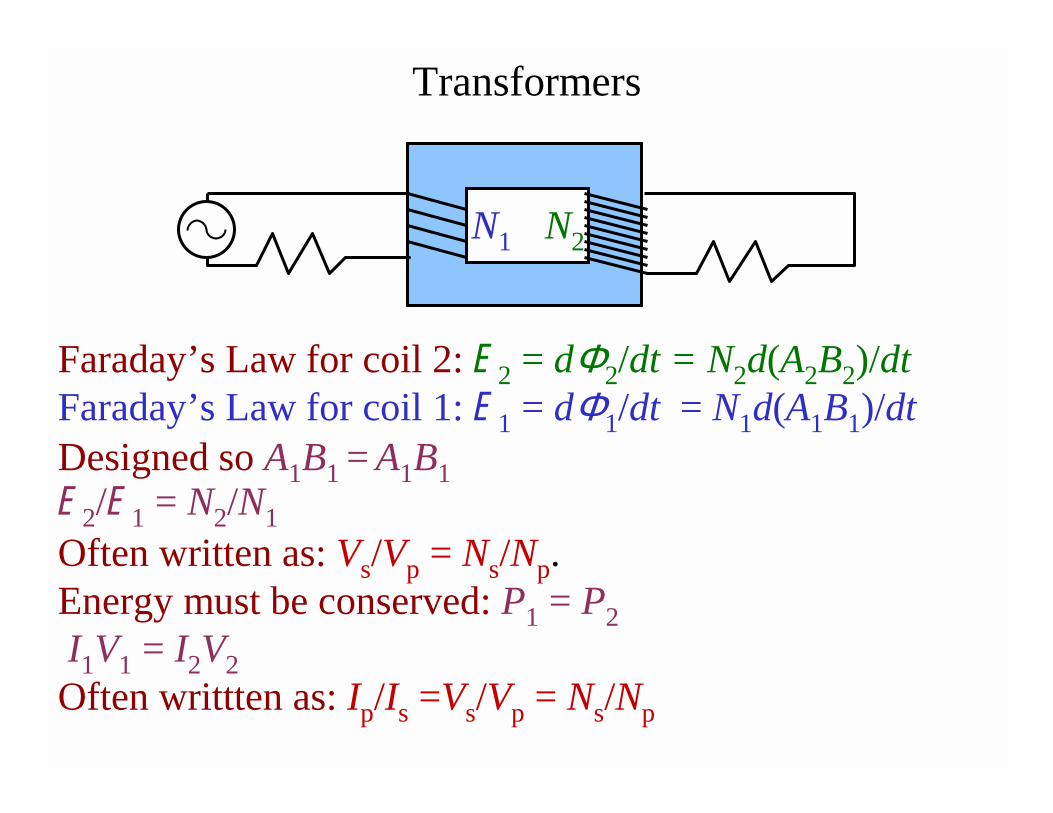
Transformers
Faraday’s Law for coil 2: E2 = dΦ2/dt = N2d(A2B2)/dt Faraday’s Law for coil 1: E1 = dΦ1/dt = N1d(A1B1)/dtDesigned so A1B1 = A1B1E2/E1 = N2/N1
Often written as: Vs/Vp = Ns/Np.Energy must be conserved: P1 = P2
I1V1 = I2V2
Often writtten as: Ip/Is =Vs/Vp = Ns/Np
N1 N2
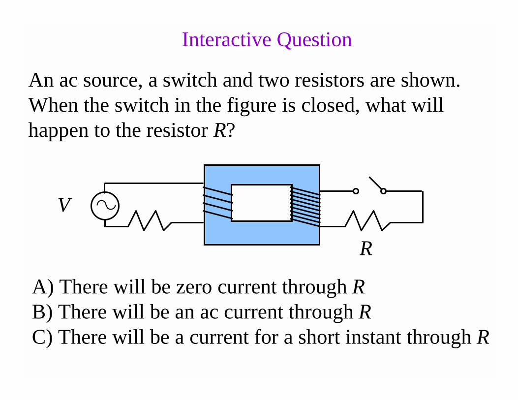
An ac source, a switch and two resistors are shown. When the switch in the figure is closed, what will happen to the resistor R?
R
V
A) There will be zero current through RB) There will be an ac current through RC) There will be a current for a short instant through R
Interactive Question
Problem: The input to the primary coil of a transformer is 120 V while the current in the secondary coil is 0.10 A. (a) When 60.0 W of power are delivered to the circuit attached to the secondary coil, what is the voltage across this coil?(b) If the primary coil has 20 turns, how many does the secondary coil have?

Problem: Suppose 1 MW of power is being transported over a power line that has a resistance of 20.0 Ω. How much power is lost along the line if the voltage of the line is (a) 240 V (b) 24,000 V?
V
VR
PR = IVR = I2RP = IV
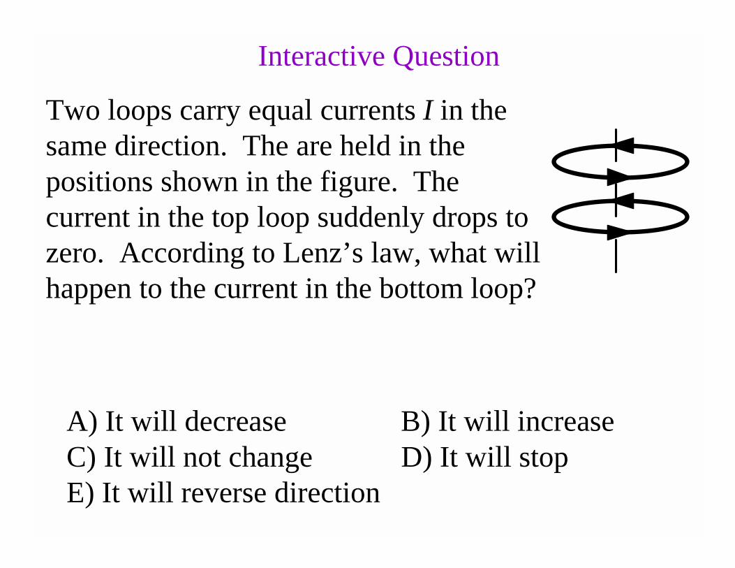
Two loops carry equal currents I in the same direction. The are held in the positions shown in the figure. The current in the top loop suddenly drops to zero. According to Lenz’s law, what will happen to the current in the bottom loop?
A) It will decrease B) It will increaseC) It will not change D) It will stopE) It will reverse direction
Interactive Question
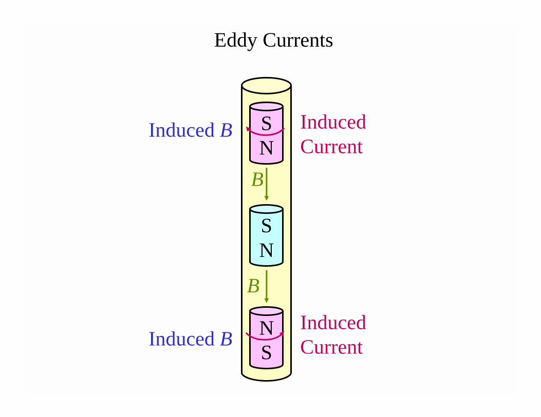
SN
B
B
Induced B
Induced BNS
SN
Induced Current
Induced Current
Eddy Currents
NS
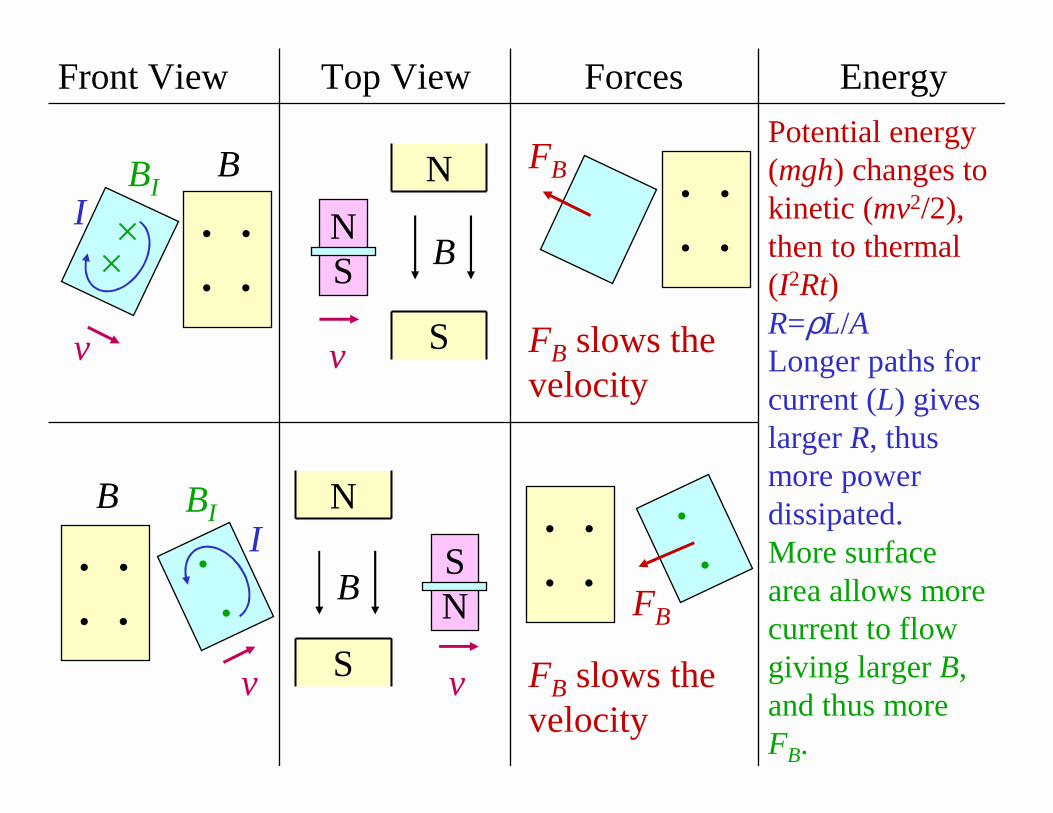
Front View Top View EnergyForces
Potential energy (mgh) changes to kinetic (mv2/2), then to thermal (I2Rt)R=ρL/ALonger paths for current (L) gives larger R, thus more power dissipated.More surface area allows more current to flow giving larger B, and thus more FB.
• •
• •
B
v
IBI
• •
• •
B
•
•
v
IBI
• •
• •
FB
FB slows the velocity
• •
• •
•
•FB
FB slows the velocity
N
N
S
S
B
BSN
v
v
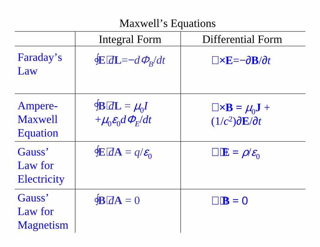
Maxwell’s Equations
Differential Form
Faraday’s Law
Ampere-Maxwell Equation
Gauss’Law for Electricity
Gauss’Law for Magnetism
∫E⋅dL=−dΦB/dt
∫B⋅dL = µ0I+µ0ε0dΦE/dt
∫E⋅dA = q/ε0
∫B⋅dA = 0
∇ ×E=−∂B/∂t
∇ ×B = µ0J + (1/c2)∂E/∂t
∇⋅ E = ρ/ε0
∇⋅ B = 0
Integral Form
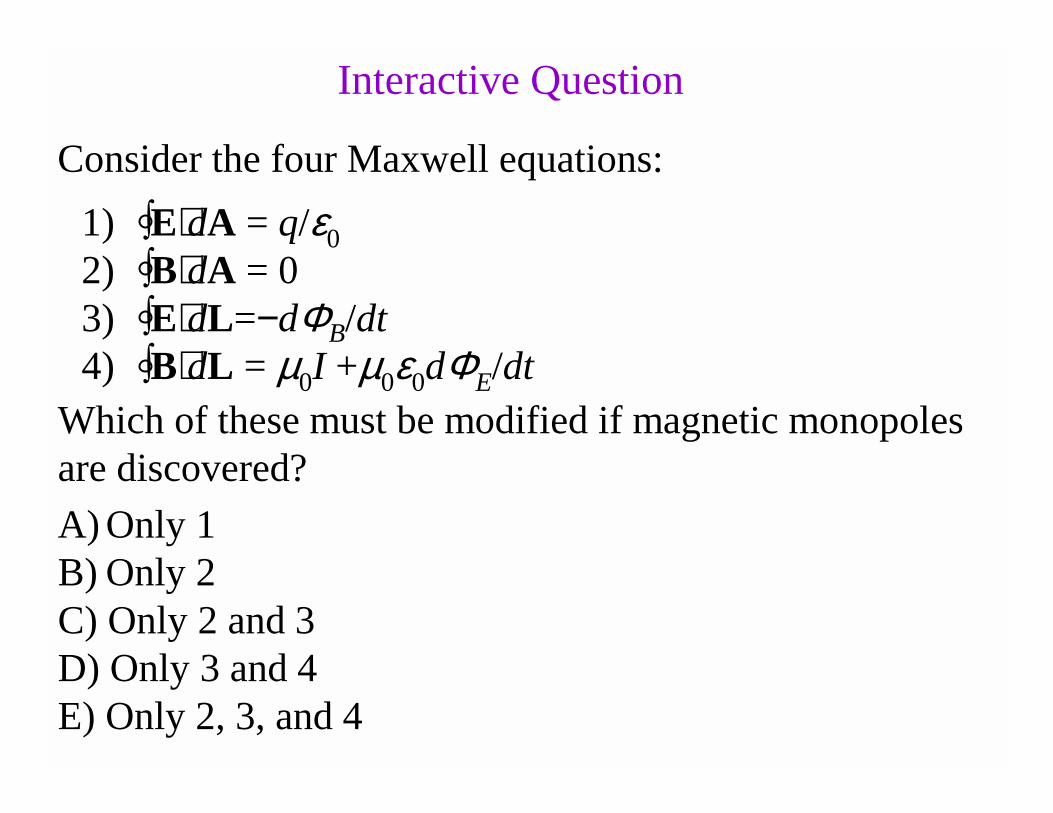
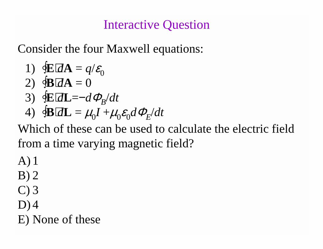
1) ∫E⋅dA = q/ε0
2) ∫B⋅dA = 03) ∫E⋅dL=−dΦB/dt4) ∫B⋅dL = µ0I +µ0ε0dΦE/dt
Consider the four Maxwell equations:
Interactive Question
Which of these must be modified if magnetic monopoles are discovered?
A) Only 1B) Only 2C) Only 2 and 3D) Only 3 and 4E) Only 2, 3, and 4
1) ∫E⋅dA = q/ε0
2) ∫B⋅dA = 03) ∫E⋅dL=−dΦB/dt4) ∫B⋅dL = µ0I +µ0ε0dΦE/dt
Consider the four Maxwell equations:
Interactive Question
Which of these can be used to calculate the electric field from a time varying magnetic field?
A) 1B) 2C) 3D) 4E) None of these
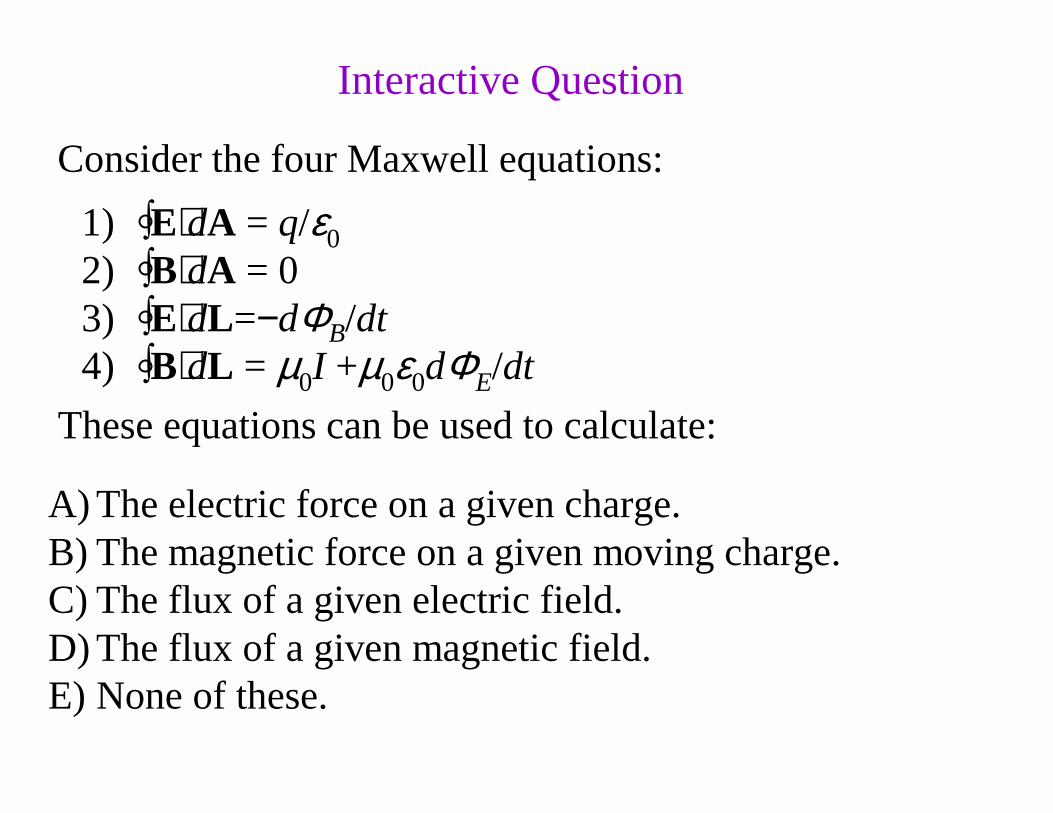
1) ∫E⋅dA = q/ε0
2) ∫B⋅dA = 03) ∫E⋅dL=−dΦB/dt4) ∫B⋅dL = µ0I +µ0ε0dΦE/dt
Consider the four Maxwell equations:
Interactive Question
These equations can be used to calculate:
A) The electric force on a given charge.B) The magnetic force on a given moving charge.C) The flux of a given electric field.D) The flux of a given magnetic field.E) None of these.
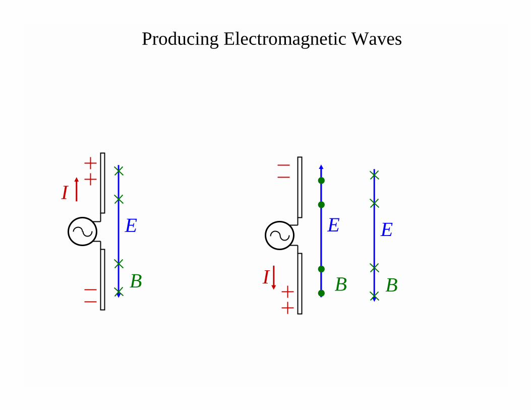
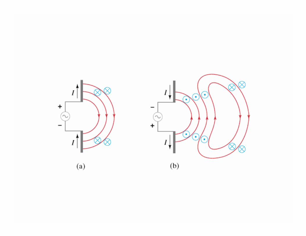
Producing Electromagnetic Waves
I
E
B I
E
B
E
B
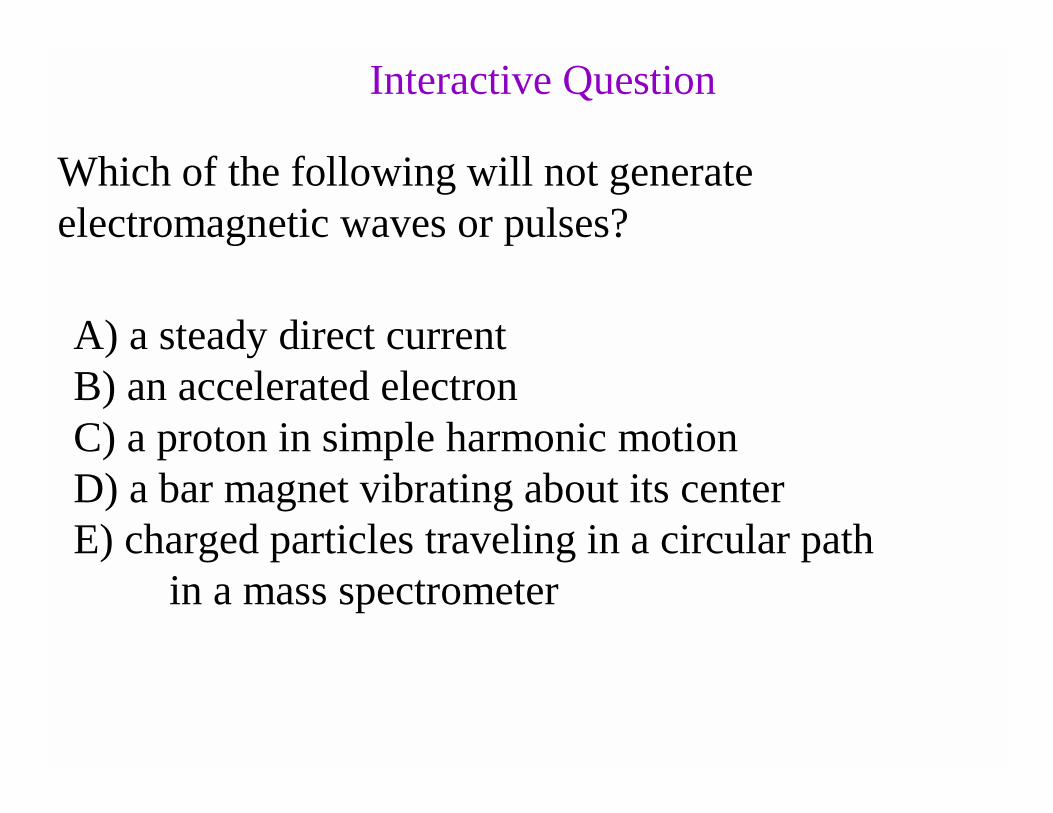
Which of the following will not generate electromagnetic waves or pulses?
A) a steady direct currentB) an accelerated electronC) a proton in simple harmonic motionD) a bar magnet vibrating about its centerE) charged particles traveling in a circular path
in a mass spectrometer
Interactive Question
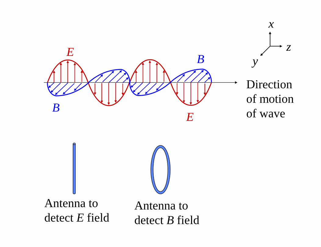
E
EB
B
Direction of motion of wave
x
yz
Antenna to detect E field
Antenna to detect B field
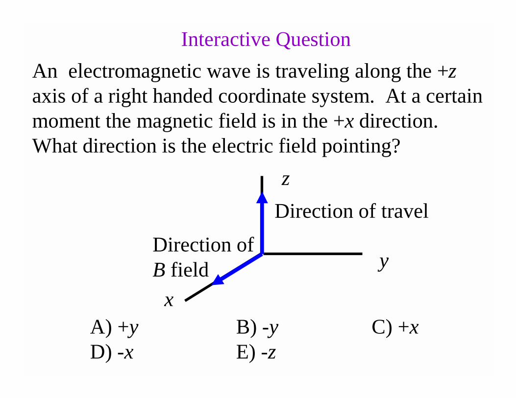
An electromagnetic wave is traveling along the +zaxis of a right handed coordinate system. At a certain moment the magnetic field is in the +x direction. What direction is the electric field pointing?
A) +y B) -y C) +xD) -x E) -z
z
x
y
Direction of travel
Direction ofB field
Interactive Question
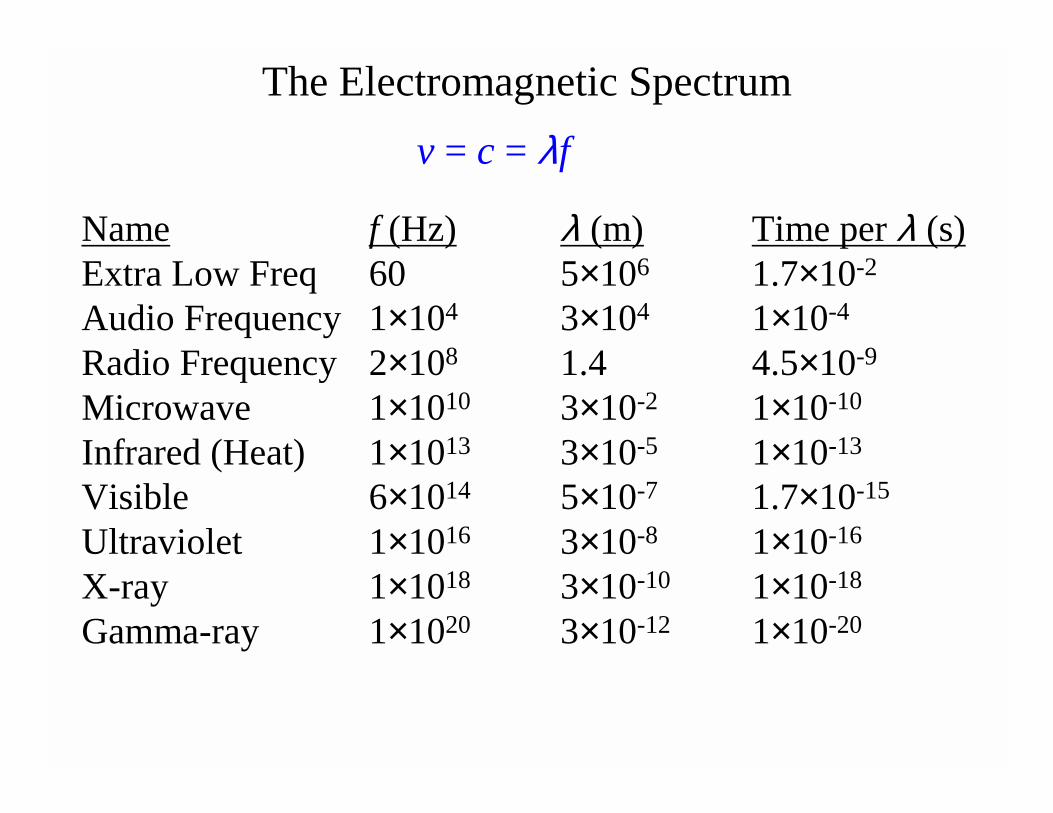
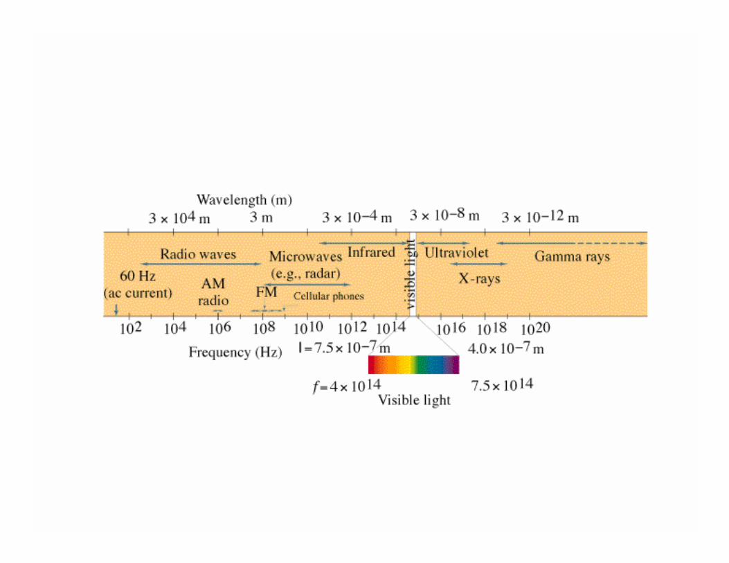
The Electromagnetic Spectrum
v = c = λf
Name f (Hz) λ (m) Time per λ (s)Extra Low Freq 60 5×10⁶ 1.7×10⁻²
Audio Frequency 1×10⁴ 3×10⁴ 1×10⁻⁴
Radio Frequency 2×10⁸ 1.4 4.5×10⁻⁹
Microwave 1×10¹⁰ 3×10⁻² 1×10⁻¹⁰
Infrared (Heat) 1×10¹³ 3×10⁻⁵ 1×10-13
Visible 6×10¹⁴ 5×10⁻⁷ 1.7×10⁻¹⁵
Ultraviolet 1×10¹⁶ 3×10⁻⁸ 1×10-16
X-ray 1×10¹⁸ 3×10⁻¹⁰ 1×10-18
Gamma-ray 1×10²⁰ 3×10-12 1×10-20
The various colors of visible light differ in
A) frequency only.B) wavelength only.C) their speeds in a vacuum.D) frequency and wavelength.E) frequency and their speed in a vacuum.
Interactive Question
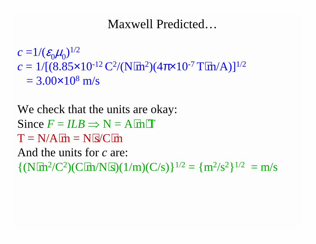
c =1/(ε0µ0)1/2
c = 1/[(8.85×10-12 C2/(N⋅m2)(4π×10-7 T⋅m/A)]1/2
= 3.00×10⁸ m/s
We check that the units are okay:Since F = ILB ⇒ N = A⋅m⋅TT = N/A⋅m = N⋅s/C⋅mAnd the units for c are:(N⋅m2/C2)(C⋅m/N⋅s)(1/m)(C/s)1/2 = m2/s21/2 = m/s
Maxwell Predicted…
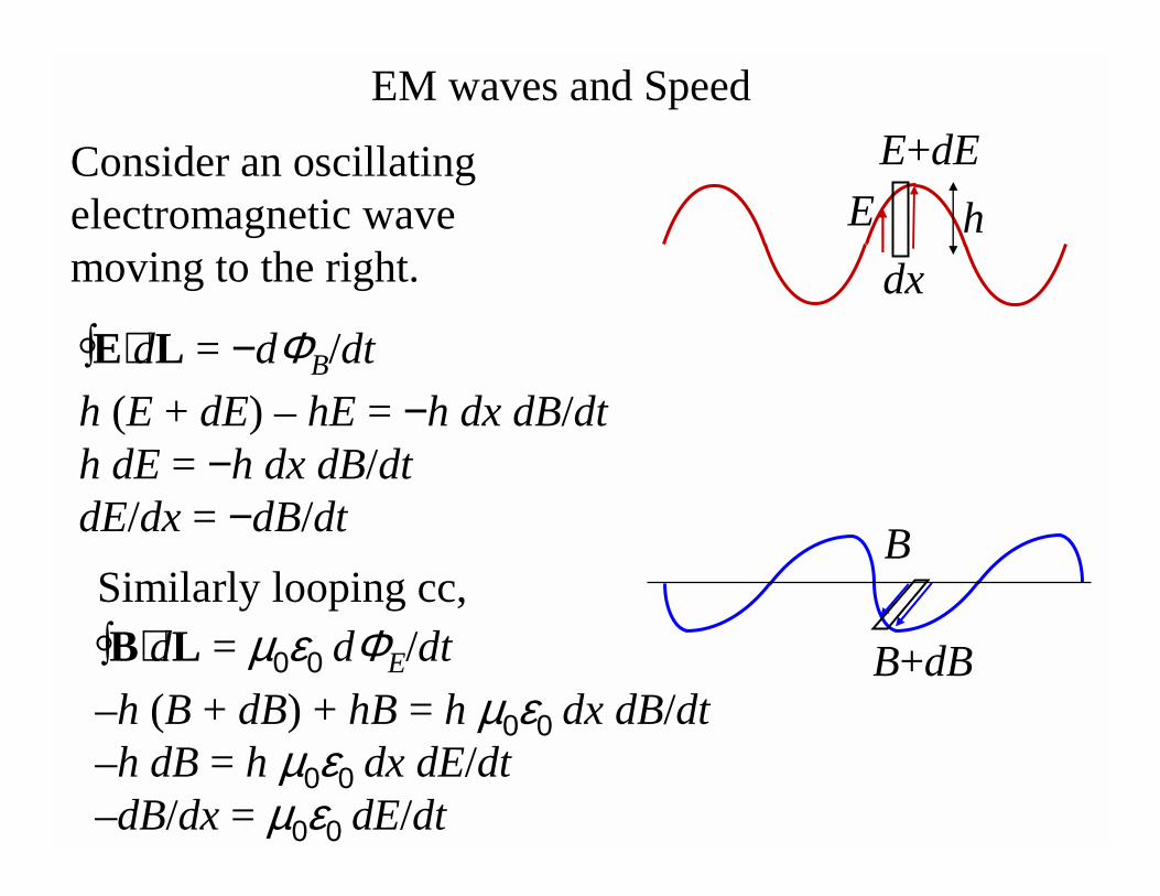
EM waves and Speed
∫E⋅dL = −dΦB/dt
Consider an oscillating electromagnetic wave moving to the right.
h
dx
E
E+dE
h (E + dE) – hE = −h dx dB/dth dE = −h dx dB/dtdE/dx = −dB/dt
Similarly looping cc,
∫B⋅dL = µ0ε0 dΦE/dt
–h (B + dB) + hB = h µ0ε0 dx dB/dt–h dB = h µ0ε0 dx dE/dt–dB/dx = µ0ε0 dE/dt
B+dB
B
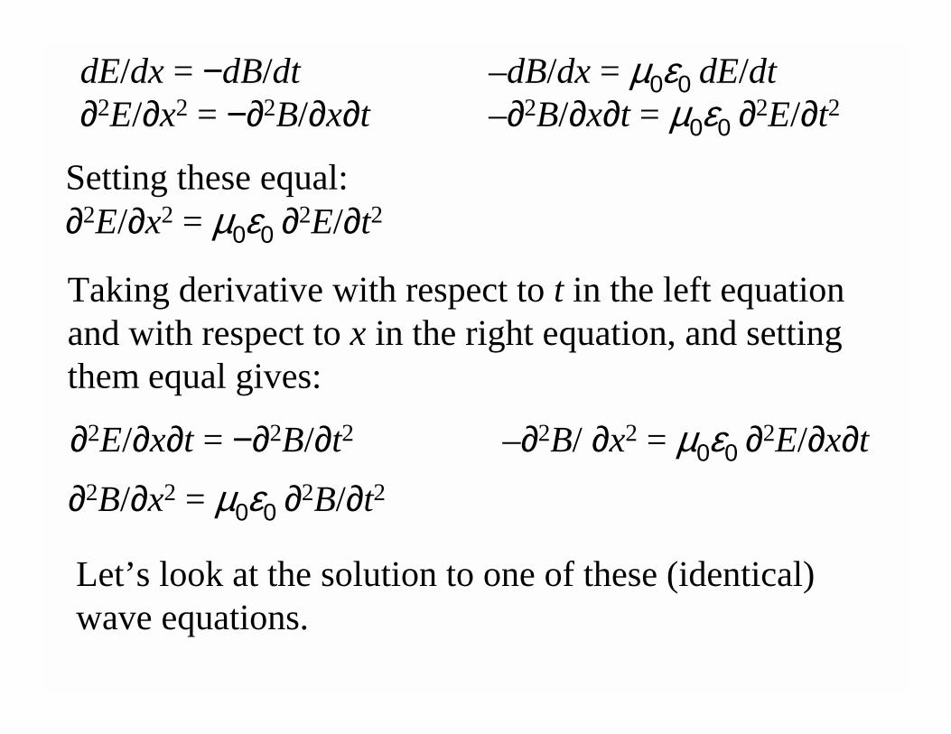
–dB/dx = µ0ε0 dE/dt–∂2B/∂x∂t = µ0ε0 ∂2E/∂t2
dE/dx = −dB/dt∂2E/∂x2 = −∂2B/∂x∂t
Setting these equal:∂2E/∂x2 = µ0ε0 ∂2E/∂t2
Taking derivative with respect to t in the left equation and with respect to x in the right equation, and setting them equal gives:
∂2B/∂x2 = µ0ε0 ∂2B/∂t2
∂2E/∂x∂t = −∂2B/∂t2 –∂2B/ ∂x2 = µ0ε0 ∂2E/∂x∂t
Let’s look at the solution to one of these (identical) wave equations.
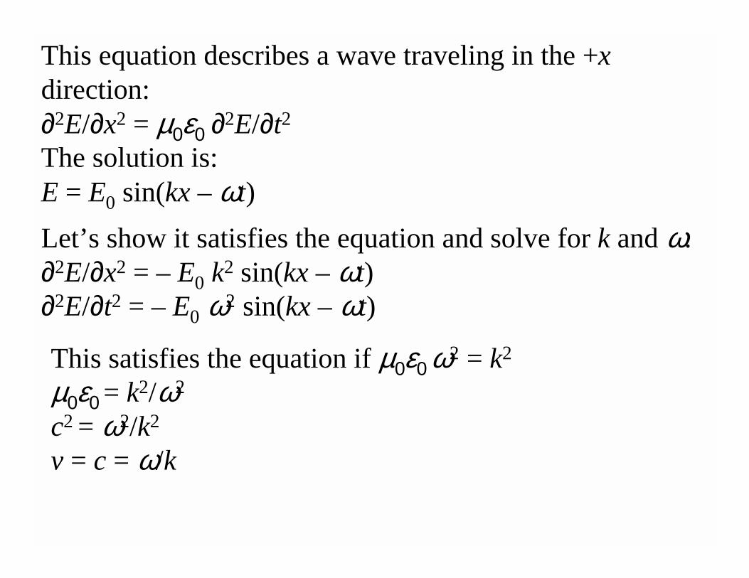
This equation describes a wave traveling in the +xdirection:∂2E/∂x2 = µ0ε0 ∂2E/∂t2
The solution is:E = E0 sin(kx – ωt)
Let’s show it satisfies the equation and solve for k and ω.∂2E/∂x2 = – E0 k2 sin(kx – ωt)∂2E/∂t2 = – E0 ω2 sin(kx – ωt)
This satisfies the equation if µ0ε0 ω2 = k2
µ0ε0 = k2/ω2
c2 = ω2/k2
v = c = ω/k
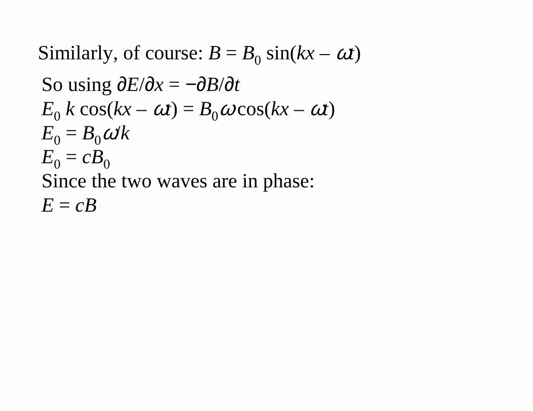
Similarly, of course: B = B0 sin(kx – ωt)
So using ∂E/∂x = −∂B/∂tE0 k cos(kx – ωt) = B0ωcos(kx – ωt)E0 = B0ω/kE0 = cB0
Since the two waves are in phase:E = cB
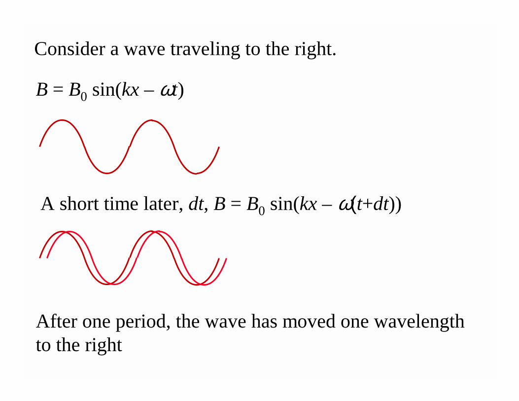
B = B0 sin(kx – ωt)
Consider a wave traveling to the right.
A short time later, dt, B = B0 sin(kx – ω(t+dt))
After one period, the wave has moved one wavelength to the right
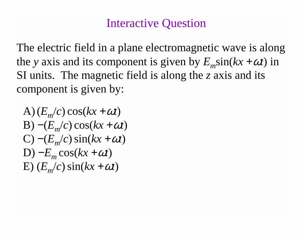
The electric field in a plane electromagnetic wave is along the y axis and its component is given by Emsin(kx +ωt) in SI units. The magnetic field is along the z axis and its component is given by:
Interactive Question
A) (Em/c) cos(kx +ωt)B) −(Em/c) cos(kx +ωt)C) −(Em/c) sin(kx +ωt)D) −Em cos(kx +ωt)E) (Em/c) sin(kx +ωt)
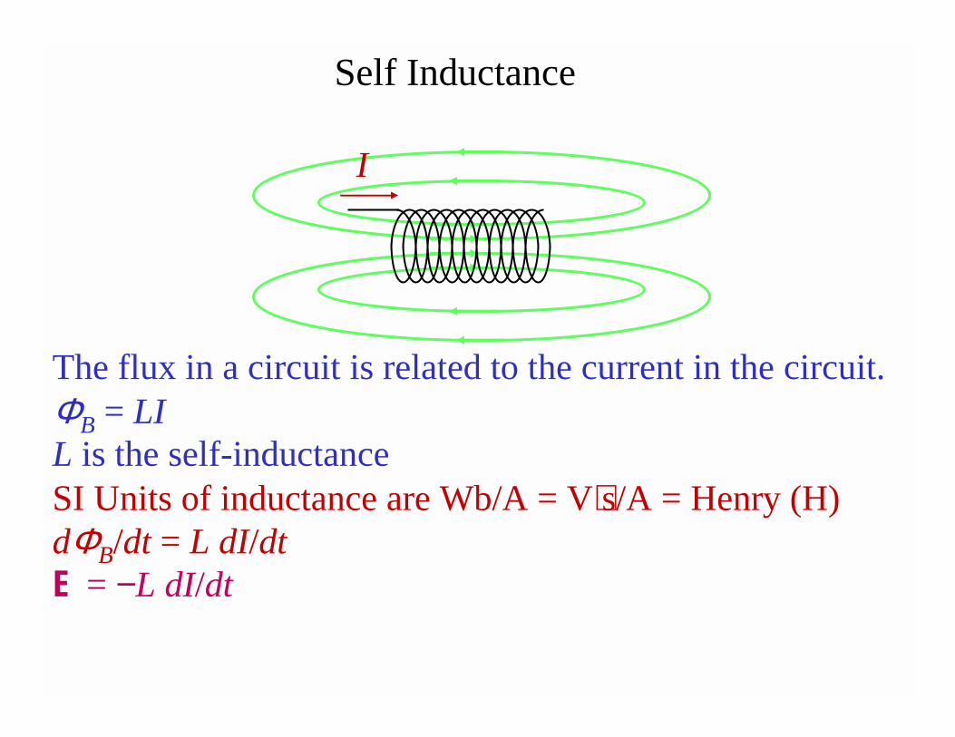
Self Inductance
The flux in a circuit is related to the current in the circuit. ΦB = LIL is the self-inductance SI Units of inductance are Wb/A = V⋅s/A = Henry (H)dΦB/dt = L dI/dtE = −L dI/dt
I
Problem: What is the self inductance of a solenoid?
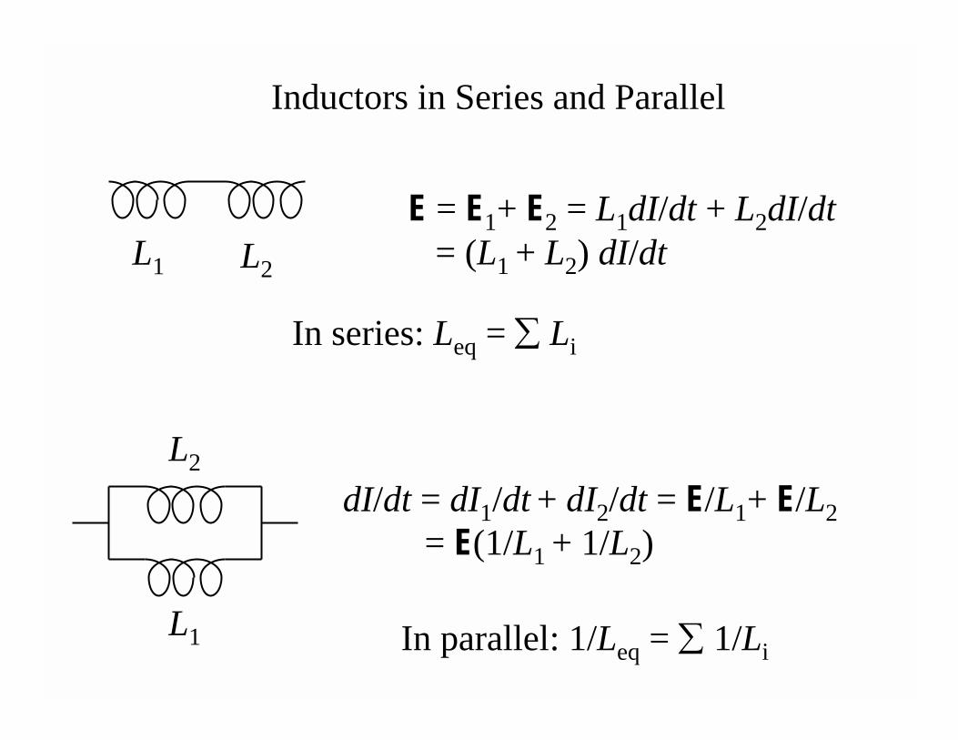
Inductors in Series and Parallel
E = E1+ E2 = L1dI/dt + L2dI/dt= (L1 + L2) dI/dtL1 L2
In series: Leq = ∑ Li
dI/dt = dI1/dt + dI2/dt = E/L1+ E/L2
= E(1/L1 + 1/L2)
L1
L2
In parallel: 1/Leq = ∑ 1/Li
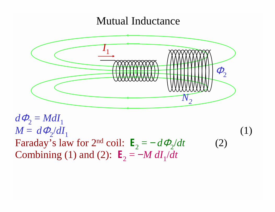
Mutual Inductance
dΦ2 = MdI1
M = dΦ2/dI1 (1)Faraday’s law for 2nd coil: E2 = −dΦ2/dt (2) Combining (1) and (2): E2 = −M dI1/dt
I1
Φ2
N2

r
Coil 1
Coil 2
A B CS
When the switch S is initially closedA) a current will flow from left to right in rB) an induced current will flow from right to left in RC) a magnetic field that points toward B appears in 1D) an induced magnetic field that points toward B appears
in 2E) a current flows through r, but not through R
Two coils, 1 and 2, with iron cores are positioned as shown. Coil 1 is connected to a battery and a switch.
Interactive Question
R
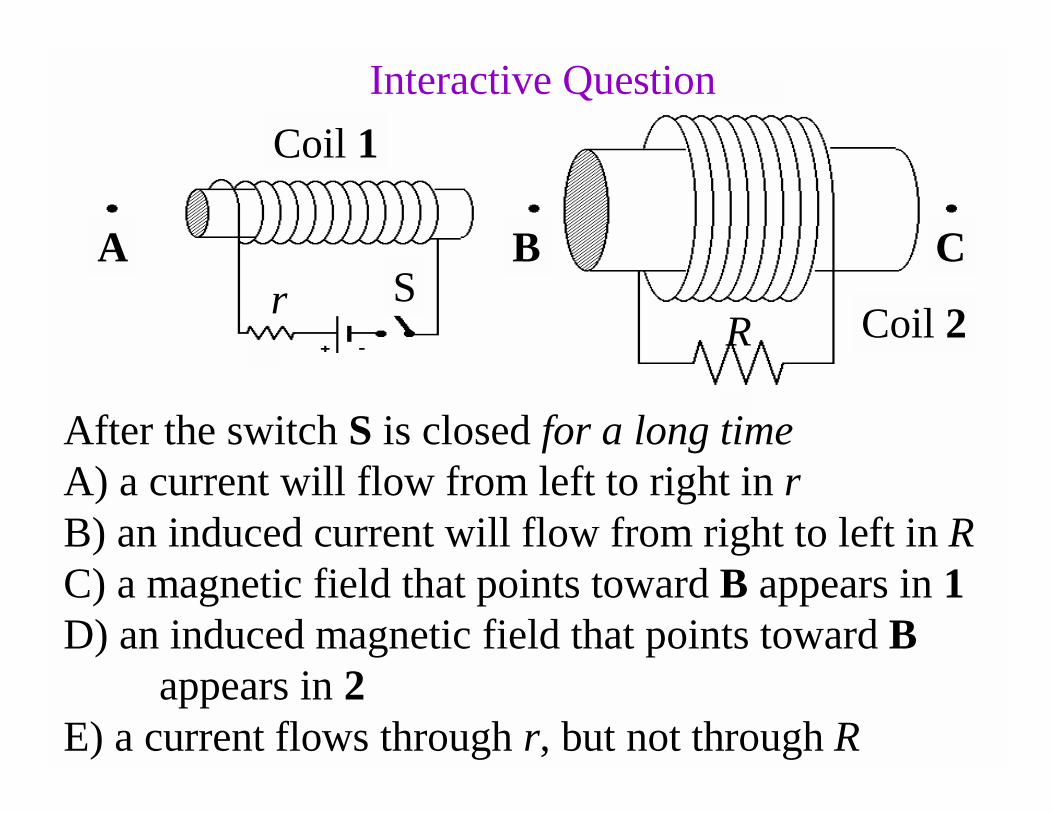
After the switch S is closed for a long timeA) a current will flow from left to right in rB) an induced current will flow from right to left in RC) a magnetic field that points toward B appears in 1D) an induced magnetic field that points toward B
appears in 2E) a current flows through r, but not through R
rR
Coil 1
Coil 2
A BS
C
Interactive Question

Problem: Consider two solenoids of equal length L, placed coaxially, one inside the other. The inner one has a radius R1 , current I1, and N1 coils, and the outer one has radius R2, current I2, with N2 coils. What is the mutual inductance of this setup?
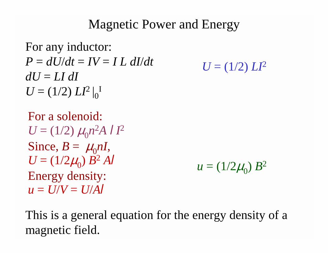
Magnetic Power and Energy
For a solenoid:U = (1/2) µ0n
2A l I2
Since, B = µ0nI,U = (1/2µ0) B
2 AlEnergy density:u = U/V = U/Al
U = (1/2) LI2
This is a general equation for the energy density of a magnetic field.
u = (1/2µ0) B2
For any inductor:P = dU/dt = IV = I L dI/dtdU = LI dIU = (1/2) LI2 |0
I
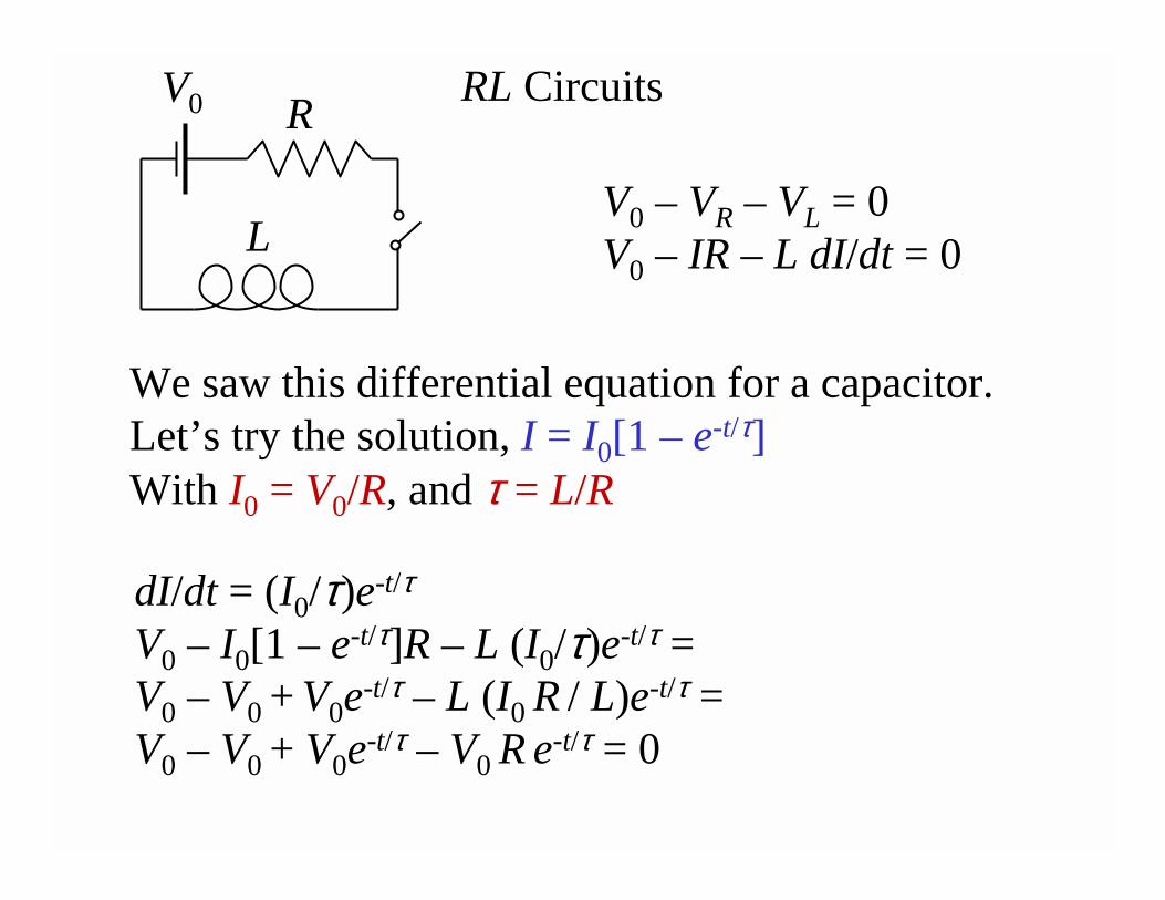
RL Circuits
V0 – VR – VL = 0V0 – IR – L dI/dt = 0
We saw this differential equation for a capacitor.Let’s try the solution, I = I0[1 – e-t/τ]With I0 = V0/R, and τ = L/R
V0 R
L
dI/dt = (I0/τ)e-t/τ
V0 – I0[1 – e-t/τ]R – L (I0/τ)e-t/τ = V0 – V0 + V0e
-t/τ – L (I0 R / L)e-t/τ = V0 – V0 + V0e
-t/τ – V0 R e-t/τ = 0
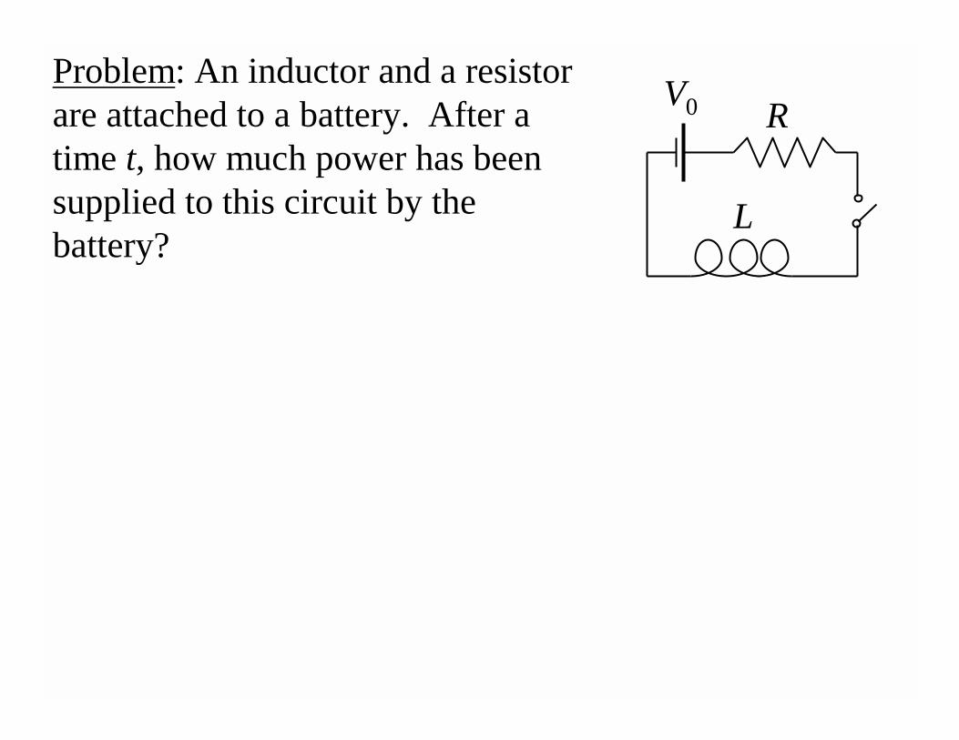
Problem: An inductor and a resistor are attached to a battery. After a time t, how much power has been supplied to this circuit by the battery?
V0 R
L
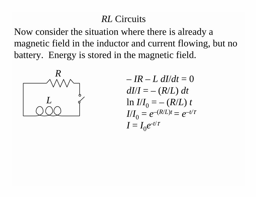
RL Circuits
– IR – L dI/dt = 0dI/I = – (R/L) dtln I/I0 = – (R/L) tI/I0 = e–(R/L)t = e–t/τ
I = I0e-t/τ
R
L
Now consider the situation where there is already a magnetic field in the inductor and current flowing, but no battery. Energy is stored in the magnetic field.
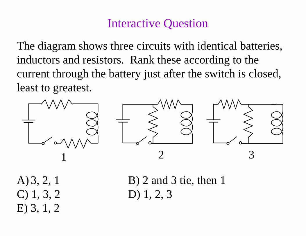
Interactive Question
The diagram shows three circuits with identical batteries, inductors and resistors. Rank these according to the current through the battery just after the switch is closed, least to greatest.
1 2 3
A) 3, 2, 1 B) 2 and 3 tie, then 1C) 1, 3, 2 D) 1, 2, 3E) 3, 1, 2
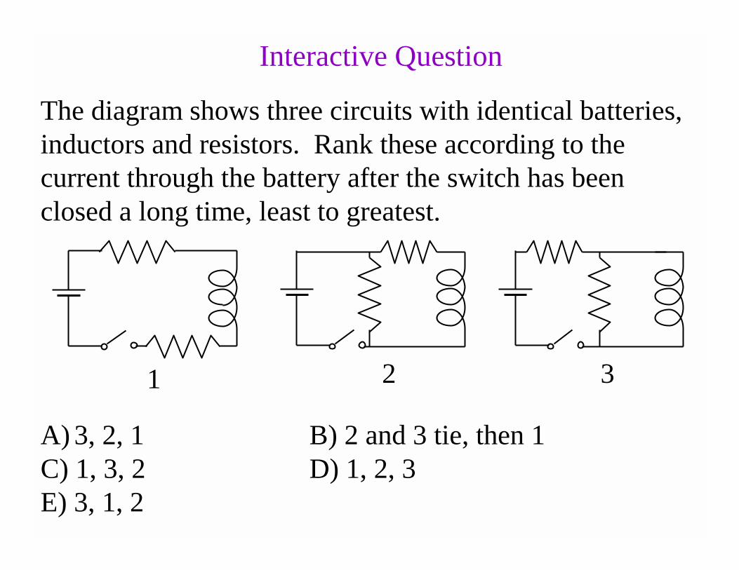
Interactive Question
The diagram shows three circuits with identical batteries, inductors and resistors. Rank these according to the current through the battery after the switch has been closed a long time, least to greatest.
1 2 3
A) 3, 2, 1 B) 2 and 3 tie, then 1C) 1, 3, 2 D) 1, 2, 3E) 3, 1, 2
Interactive Question
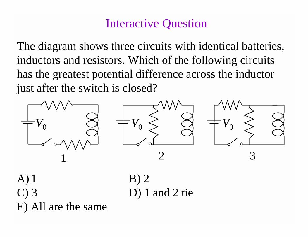
The diagram shows three circuits with identical batteries, inductors and resistors. Which of the following circuits has the greatest potential difference across the inductor just after the switch is closed?
1 2 3
A) 1 B) 2C) 3 D) 1 and 2 tieE) All are the same
V0 V0 V0
Interactive Question
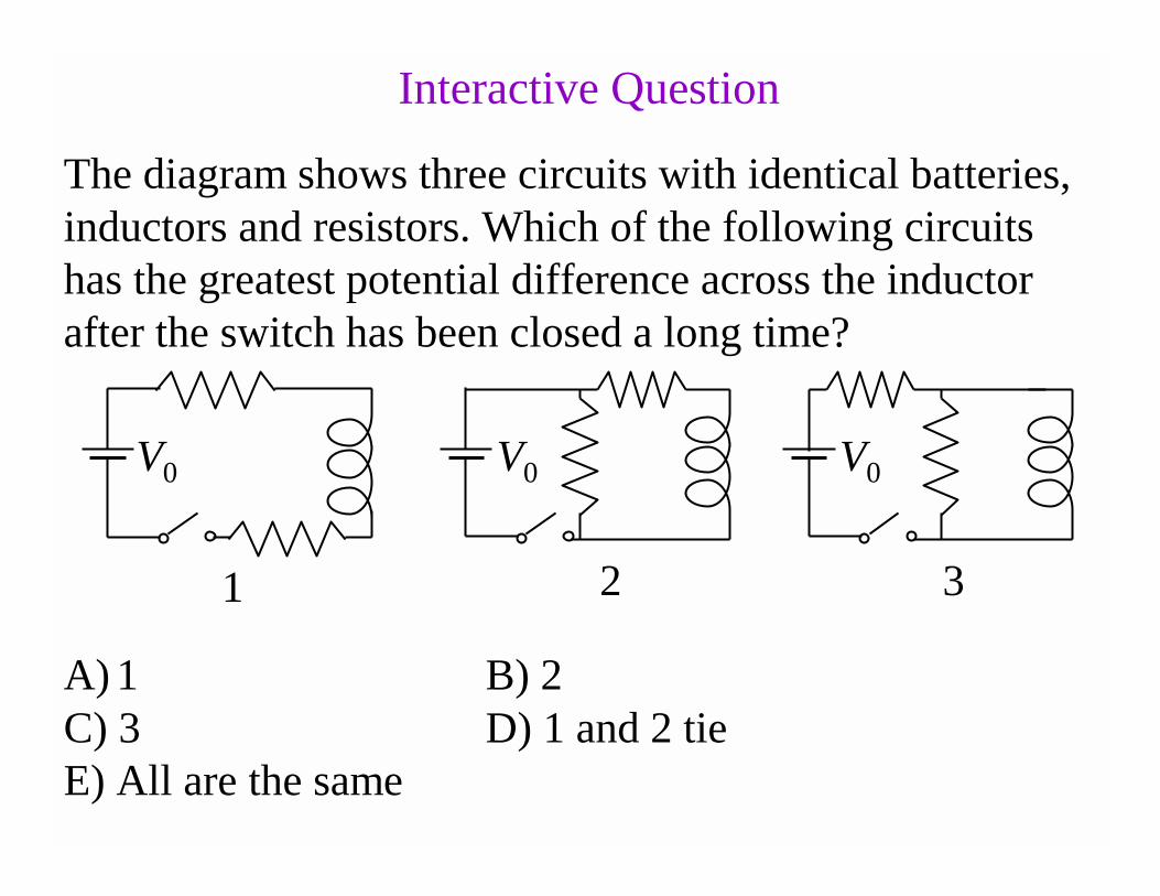
The diagram shows three circuits with identical batteries, inductors and resistors. Which of the following circuits has the greatest potential difference across the inductor after the switch has been closed a long time?
1 2 3
V0 V0 V0
A) 1 B) 2C) 3 D) 1 and 2 tieE) All are the same
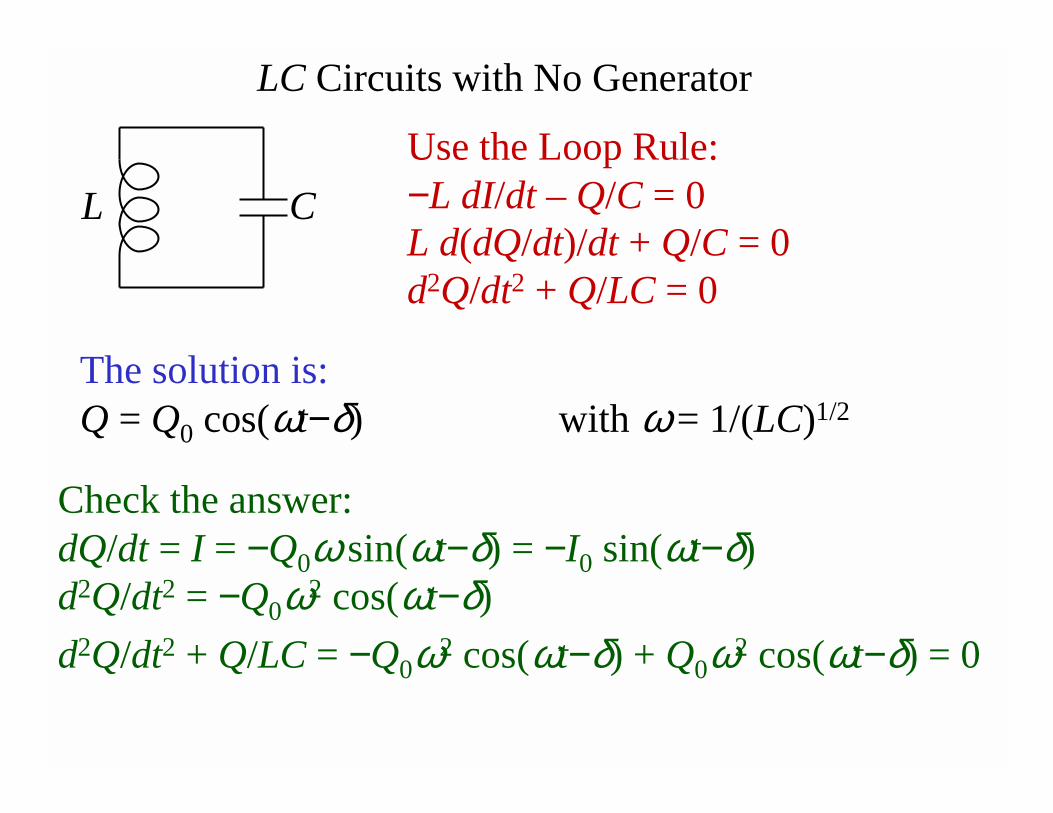
LC Circuits with No Generator
CL
Use the Loop Rule:−L dI/dt – Q/C = 0L d(dQ/dt)/dt + Q/C = 0d2Q/dt2 + Q/LC = 0
The solution is:Q = Q0 cos(ωt−δ) with ω= 1/(LC)1/2
Check the answer:dQ/dt = I = −Q0ω sin(ωt−δ) = −I0 sin(ωt−δ) d2Q/dt2 = −Q0ω2 cos(ωt−δ)
d2Q/dt2 + Q/LC = −Q0ω2 cos(ωt−δ) + Q0ω2 cos(ωt−δ) = 0
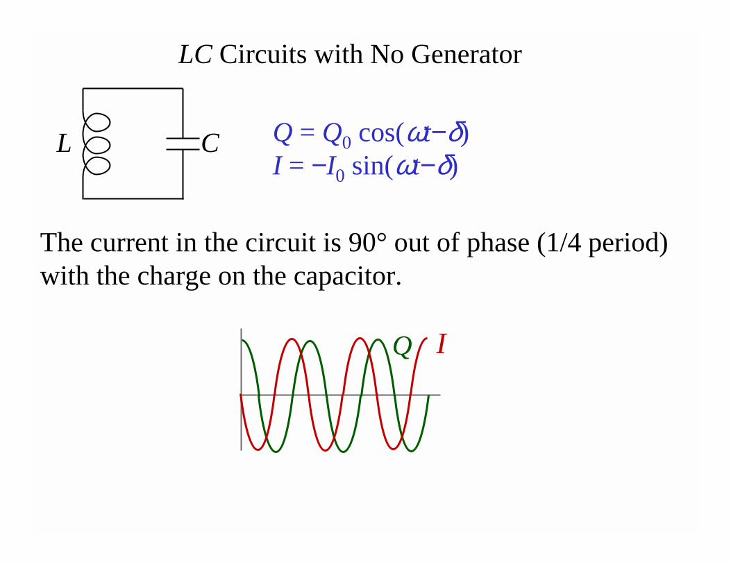
LC Circuits with No Generator
CL Q = Q0 cos(ωt−δ)I = −I0 sin(ωt−δ)
The current in the circuit is 90° out of phase (1/4 period) with the charge on the capacitor.
IQ
A charged capacitor and an inductor are connected in series. At time t=0, the current is zero. If T is the period of the resulting oscillations, then the next time, after t=0, that the charge on the capacitor is a maximum is:
A) T/4B) T/2C) TD) 2TE) 4T
Interactive Question
A charged capacitor and an inductor are connected in series. At time t=0, the current is zero. If T is the period of the resulting oscillations, then the next time, after t=0, that the voltage across the inductor is a maximum is:
A) T/4B) T/2C) TD) 3T/2E) 2T
Interactive Question
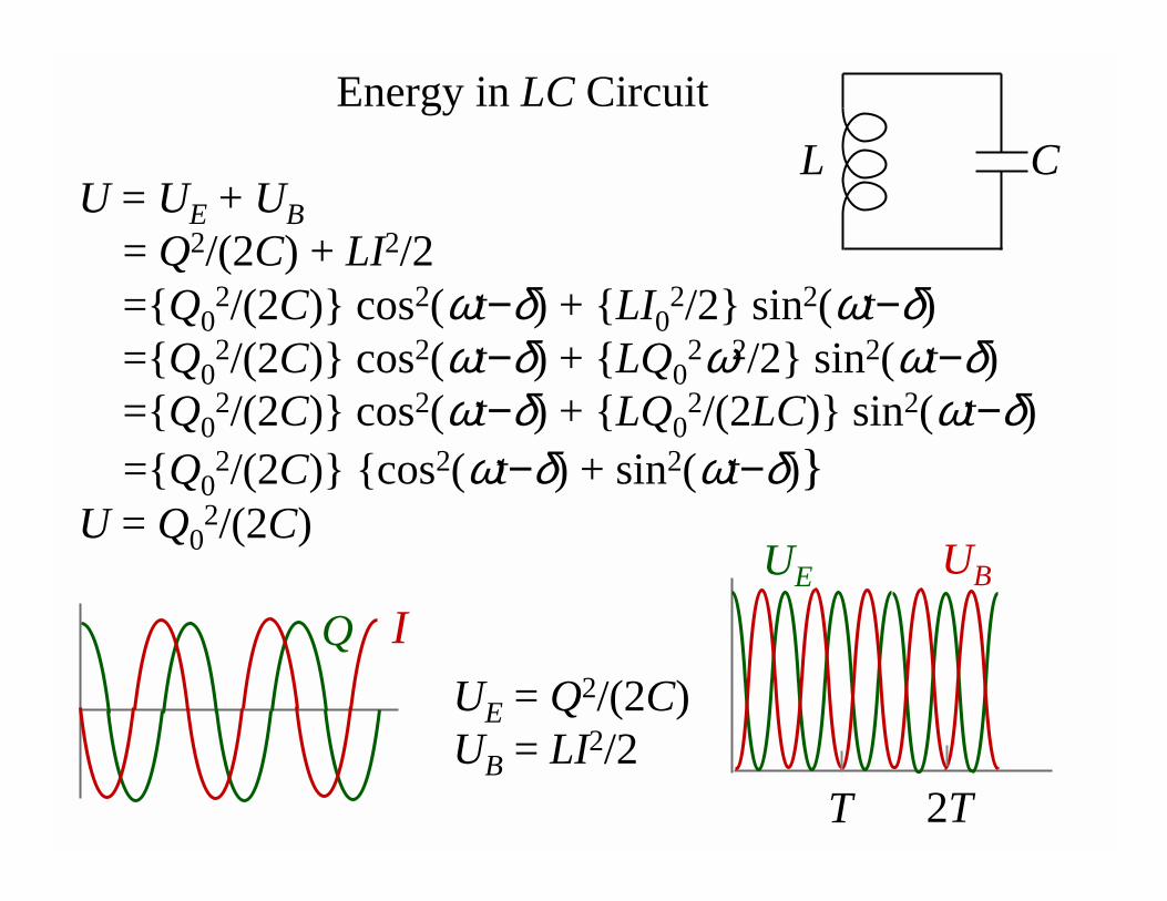
Energy in LC Circuit
U = UE + UB
= Q2/(2C) + LI2/2=Q0
2/(2C) cos2(ωt−δ) + LI02/2 sin2(ωt−δ)
=Q02/(2C) cos2(ωt−δ) + LQ0
2ω2/2 sin2(ωt−δ) =Q0
2/(2C) cos2(ωt−δ) + LQ02/(2LC) sin2(ωt−δ)
=Q02/(2C) cos2(ωt−δ) + sin2(ωt−δ)
U = Q02/(2C)
IQ
UE = Q2/(2C)UB = LI2/2
UBUE
T 2T
CL
A charged capacitor and an inductor are connected in series. At time t=0, the current is zero. If T is the period of the resulting oscillations, then the next time, after t=0, that the energy stored in the magnetic field is a maximum is:
A) T/4B) T/2C) TD) 2TE) 4T
Interactive Question
Problem: A 300 V dc power supply is used to charge a 25 µF capacitor. After the capacitor is fully charged, it is disconnected from the power supply and connected across a 10 mH inductor. The resistance is negligible.
(a) Find the capacitor charge 1.2 ms after the connection is made.
(b) Find the magnetic and electric energy at the same time.
In an oscillating LC circuit, the total stored energy is U. When Q = Q0/2, what is the energy stored in the magnetic field, UB?
A) U/4B) U/2C) UD) U/√2E) 3U/4
Interactive Question