Chapter 2...Chapter 2 2.1 The resultant of each force system is 500N ↑....
94
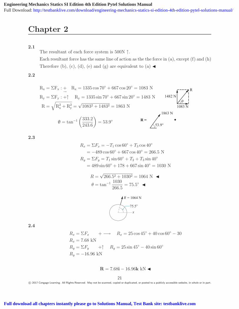
Chapter 2 2.1 The resultant of each force system is 500N ↑. Each resultant force has the same line of action as the the force in (a), except (f) and (h) Therefore (b), (c), (d), (e) and (g) are equivalent to (a) 2.2 R x = ΣF x :+ → R x = 1335 cos 70 ◦ + 667 cos 20 ◦ = 1083 N R y = ΣF y :+↑ R y = 1335 sin 70 ◦ + 667 sin 20 ◦ = 1483 N R= R 2 x +R 2 y = √ 1083 2 + 1483 2 = 1863 N R 1083 N 1482 N θ = tan −1 333.2 243.6 = 53.9 ◦ 1863 N 53.9° R = 2.3 R x =ΣF x = −T 1 cos 60 ◦ + T 3 cos 40 ◦ = −489 cos 60 ◦ + 667 cos 40 ◦ = 266.5N R y =ΣF y = T 1 sin 60 ◦ + T 2 + T 3 sin 40 ◦ = 489 sin 60 ◦ + 178 + 667 sin 40 ◦ = 1030 N R = √ 266.5 2 + 1030 2 = 1064 N θ = tan −1 1030 266.5 = 75.5 ◦ R = 1064 N 75.5 o x 2.4 R x =ΣF x + −→ R x = 25 cos 45 ◦ + 40 cos 60 ◦ − 30 R x =7.68 kN R y =ΣF y +↑ R y = 25 sin 45 ◦ − 40 sin 60 ◦ R y = −16.96 kN R =7.68i − 16.96k kN 21 c 2017 Cengage Learning. All Rights Reserved. May not be scanned, copied or duplicated, or posted to a publicly accessible website, in whole or in part. Engineering Mechanics Statics SI Edition 4th Edition Pytel Solutions Manual Full Download: http://testbanklive.com/download/engineering-mechanics-statics-si-edition-4th-edition-pytel-solutions-manual/ Full download all chapters instantly please go to Solutions Manual, Test Bank site: testbanklive.com
Transcript of Chapter 2...Chapter 2 2.1 The resultant of each force system is 500N ↑....
Chapter 2
2.1The resultant of each force system is 500N ↑.Each resultant force has the same line of action as the the force in (a), except (f) and (h)
Therefore (b), (c), (d), (e) and (g) are equivalent to (a) �
2.2
Rx = ΣFx : +→
Rx = 1335 cos 70◦ + 667 cos 20◦ = 1083 N
Ry = ΣFy : +↑ Ry = 1335 sin 70◦ + 667 sin 20◦ = 1483 N
R =√
R2x + R2
y =√
10832 + 14832 = 1863 N
R
1083 N
1482 N
θ = tan−1
(333.2
243.6
)= 53.9◦
1863 N
53.9°R =
2.3
Rx = ΣFx = −T1 cos 60◦ + T3 cos 40◦
= −489 cos 60◦ + 667 cos 40◦ = 266.5 N
Ry = ΣFy = T1 sin 60◦ + T2 + T3 sin 40◦
= 489 sin 60◦ + 178 + 667 sin 40◦ = 1030 N
R =√
266.52 + 10302 = 1064 N �θ = tan−1 1030
266.5= 75.5◦ �
R = 1064 N
75.5o
x
2.4
Rx = ΣFx + −→ Rx = 25 cos 45◦ + 40 cos 60◦ − 30
Rx = 7.68 kN
Ry = ΣFy +↑ Ry = 25 sin 45◦ − 40 sin 60◦
Ry = −16.96 kN
R = 7.68i − 16.96k kN �
21c© 2017 Cengage Learning. All Rights Reserved. May not be scanned, copied or duplicated, or posted to a publicly accessible website, in whole or in part.
Engineering Mechanics Statics SI Edition 4th Edition Pytel Solutions ManualFull Download: http://testbanklive.com/download/engineering-mechanics-statics-si-edition-4th-edition-pytel-solutions-manual/
Full download all chapters instantly please go to Solutions Manual, Test Bank site: testbanklive.com
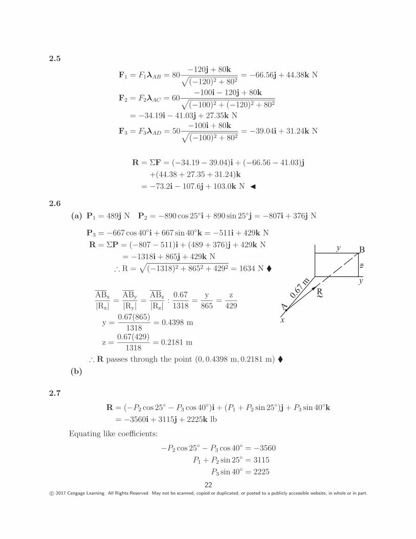
2.5
F1 = F1λAB = 80−120j + 80k√(−120)2 + 802
= −66.56j + 44.38k N
F2 = F2λAC = 60−100i − 120j + 80k√
(−100)2 + (−120)2 + 802
= −34.19i − 41.03j + 27.35k N
F3 = F3λAD = 50−100i + 80k√(−100)2 + 802
= −39.04i + 31.24k N
R = ΣF = (−34.19 − 39.04)i + (−66.56 − 41.03)j
+(44.38 + 27.35 + 31.24)k
= −73.2i − 107.6j + 103.0k N �
2.6
(a) P1 = 489j N P2 = −890 cos 25◦i + 890 sin 25◦j = −807i + 376j N
P3 = −667 cos 40◦i + 667 sin 40◦k = −511i + 429k N
R = ΣP = (−807 − 511)i + (489 + 376)j + 429k N
= −1318i + 865j + 429k N
∴ R =√
(−1318)2 + 8652 + 4292 = 1634 N �
ABx
|Rx|=
ABy
|Ry|=
ABz
|Rz|:
0.67
1318=
y
865=
z
429
y =0.67(865)
1318= 0.4398 m
z =0.67(429)
1318= 0.2181 m
R
y
y
x
B
z
A
0.67 m
∴ R passes through the point (0, 0.4398 m, 0.2181 m) �(b)
2.7
R = (−P2 cos 25◦ − P3 cos 40◦)i + (P1 + P2 sin 25◦)j + P3 sin 40◦k
= −3560i + 3115j + 2225k lb
Equating like coefficients:
−P2 cos 25◦ − P3 cos 40◦ = −3560
P1 + P2 sin 25◦ = 3115
P3 sin 40◦ = 2225
22c© 2017 Cengage Learning. All Rights Reserved. May not be scanned, copied or duplicated, or posted to a publicly accessible website, in whole or in part.
Solution is
P1 = 2690 N � P2 = 1000 N � P3 = 3460 N �
2.8
T1 = 90−i + 2j + 6k√(−1)2 + 22 + 62
= −14.06i + 28.11j + 84.33k kN
T2 = 60−2i − 3j + 6k√
(−2)2 + (−3)2 + 62= −17.14i − 25.71j + 51.43k kN
T3 = 402i − 3j + 6k√22 + (−3)2 + 62
= 11.43i − 17.14j + 34.29k kN
R = T1 + T2 + T3 = (−14.06 − 17.14 + 11.43)i
+(28.11 − 25.71 − 17.14)j + (84.33 + 51.43 + 34.29)k
= −19.77i − 14.74j + 170.05k kN �
2.9
T1 = T1−i + 2j + 6k√(−1)2 + 22 + 62
= T1(−0.15617i + 0.3123j + 0.9370k)
T2 = T2−2i − 3j + 6k√
(−2)2 + (−3)2 + 62= T2(−0.2857i − 0.4286j + 0.8571k)
T3 = T32i − 3j + 6k√22 + (−3)2 + 62
= T3(0.2857i − 0.4286j + 0.8571k)
T1 + T2 + T3 = R
Equating like components, we get
−0.15617T1 − 0.2857T2 + 0.2857T3 = 0
0.3123T1 − 0.4286T2 − 0.4286T3 = 0
0.9370T1 + 0.8571T2 + 0.8571T3 = 210
Solution is
T1 = 134.5 kN � T2 = 12.24 kN � T3 = 85.8 kN �
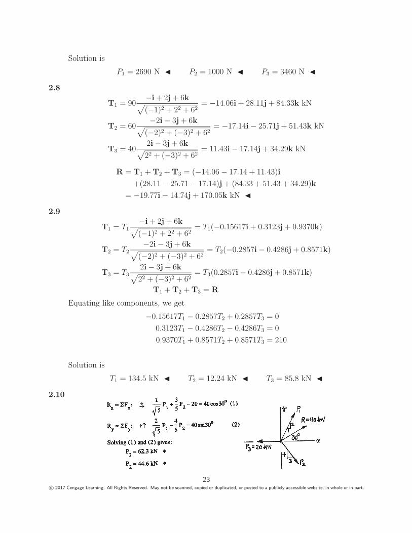
2.10
23c© 2017 Cengage Learning. All Rights Reserved. May not be scanned, copied or duplicated, or posted to a publicly accessible website, in whole or in part.
2.11
F1 = −45 cos 20◦i − 45 sin 20◦j = −42.29i − 15.39j N
F2 = F2(sin 60◦i + cos 60◦j) = F2(0.8660i + 0.5j)
R = ΣF = (−42.29 + 0.8660F2)i + (−15.39 + 0.5F2)j−→AB = −102i + 152j mm
Because R and−→AB are parallel, their components are proportional:
−42.29 + 0.8660F2
−102=
−15.39 + 0.5F2
152F2 = 60.3 N �
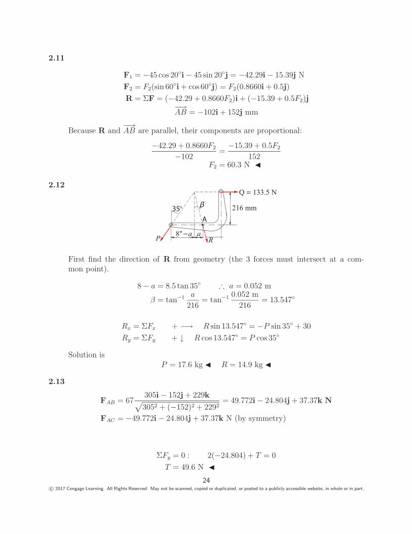
2.12
a
216 mm
8" a
o
Q 133.5 N
RP
First find the direction of R from geometry (the 3 forces must intersect at a com-mon point).
8 − a = 8.5 tan 35◦ ∴ a = 0.052 m
β = tan−1 a
216= tan−1 0.052 m
216= 13.547◦
Rx = ΣFx + −→ R sin 13.547◦ = −P sin 35◦ + 30
Ry = ΣFy + ↓ R cos 13.547◦ = P cos 35◦
Solution isP = 17.6 kg � R = 14.9 kg �
2.13
FAB = 67305i − 152j + 229k√3052 + (−152)2 + 2292
= 49.772i − 24.804j + 37.37k N
FAC = −49.772i − 24.804j + 37.37k N (by symmetry)
ΣFy = 0 : 2(−24.804) + T = 0
T = 49.6 N �24
c© 2017 Cengage Learning. All Rights Reserved. May not be scanned, copied or duplicated, or posted to a publicly accessible website, in whole or in part.
2.14
P1 = 4450.915i + 1.22k√0.9152 + 1.222
= 267i + 356k N
P2 = 5340.915i + 0.915j + 1.22k√0.9152 + 0.9152 + 1.222
= 274.8i + 274.8j + 366.4k N
P3 = 267j N
Q1 = Q1i
Q2 = Q2−0.915i − 0.915j√
0.9152 + 0.9152= Q2(−0.7071i − 0.7071j)
Q3 = Q30.915j + 1.22k√0.9152 + 1.222
= Q3(0.6j + 0.8k)
Equating similar components of ΣQ = ΣP:
Q1 − 0.7071Q2 = 267 + 274.8
−0.7071Q2 + 0.6Q3 = 274.8 + 267
0.8Q3 = 356 + 366.4
Solution isQ1 = 541.8 N � Q2 = 0 Q3 = 903 N �
2.15
Rx = ΣFx + −→ 35.6 = 178 sin 45◦ − Q sin 30◦ Q = 180.5 N
Ry = ΣFy + ↑ 0 = 178 cos 45◦ − W + 180.5 cos 30◦
∴ W = 282.2 N �
2.16
50oP2 P3
b4 m 6 m
h
40oP1
The forces must be concurrent. From geometry:
h = (4 + b) tan 40◦ = (6 − b) tan 50◦ ∴ b = 1.8682 m �∴ h = (4 + 1.8682) tan 40◦ = 4.924 m
θ = tan−1 h
b= tan−1 4.924
1.8682= 69.22◦ �
25c© 2017 Cengage Learning. All Rights Reserved. May not be scanned, copied or duplicated, or posted to a publicly accessible website, in whole or in part.
R = ΣF = (25 cos 40◦ + 60 cos 69.22◦ − 80 cos 50◦)i
+(25 sin 40◦ + 60 sin 69.22◦ + 80 sin 50◦)j
= −10.99i + 133.45j kN �
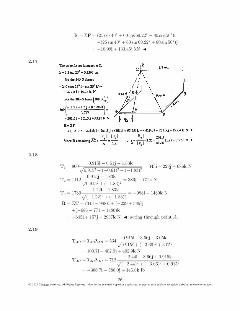
2.17
2.18
T1 = 8000.915i − 0.61j − 1.83k√
0.9152 + (−0.61)2 + (−1.83)2= 343i − 229j − 686k N
T2 = 11120.915j − 1.83k√0.9152 + (−1.83)2
= 386j − 771k N
T3 = 1780−1.22i − 1.83k√
(−1.22)2 + (−1.83)2= −988i − 1480k N
R = ΣT = (343 − 988)i + (−229 + 386)j
+(−686 − 771 − 1480)k
= −645i + 157j − 2937k N � acting through point A.
2.19
TAB = TABλAB = 5340.915i − 3.66j + 3.05k√0.9152 + (−3.66)2 + 3.052
= 100.7i − 402.9j + 402.9k N
TAC = TACλAC = 712−2.44i − 3.66j + 0.915k√
(−2.44)2 + (−3.66)2 + 0.9152
= −386.7i − 580.0j + 145.0k lb
26c© 2017 Cengage Learning. All Rights Reserved. May not be scanned, copied or duplicated, or posted to a publicly accessible website, in whole or in part.
R = TAB + TAC − Wk
= (100.7 − 386.7)i + (−402.9 − 580.0)j + (402.9 + 145.0 − 480)k
= −286.0i − 982.9j + 67.9k N �
2.20Choose the line of action of the middle force as the x-axis.
F
F
F
25o
40o
y
x
Rx = ΣFx = F (cos 25◦ + 1 + cos 40◦) = 2.672F
Ry = ΣFy = F (sin 25◦ − sin 40◦) = −0.2202F
R = F√
2.6722 + (−0.2202)2 = 2.681F
1780 = 2.681F ∴ F = 664 N �
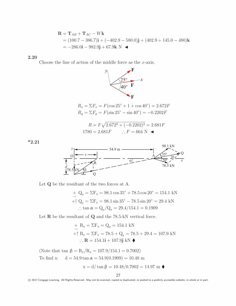
*2.21
54.9 m
78.5 kN
y
O A
d
x
Q
R
98.1 kN
35º20º
Q
x78.5 kN
Let Q be the resultant of the two forces at A.
+→
Qx = ΣFx = 98.1 cos 35◦ + 78.5 cos 20◦ = 154.1 kN
+↑ Qy = ΣFy = 98.1 sin 35◦ − 78.5 sin 20◦ = 29.4 kN
∴ tan α = Qy/Qx = 29.4/154.1 = 0.1909
Let R be the resultant of Q and the 78.5-kN vertical force.
+→
Rx = ΣFx = Qx = 154.1 kN
+↑ Ry = ΣFy = 78.5 + Qy = 78.5 + 29.4 = 107.9 kN
∴ R = 154.1i + 107.9j kN �
(Note that tan β = Ry/Rx = 107.9/154.1 = 0.7002)
To find x: d = 54.9 tan α = 54.9(0.1909) = 10.48 m
x = d/ tan β = 10.48/0.7002 = 14.97 m �
27c© 2017 Cengage Learning. All Rights Reserved. May not be scanned, copied or duplicated, or posted to a publicly accessible website, in whole or in part.
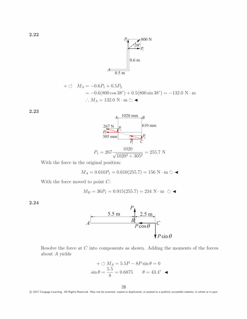
2.22800 NP
0.6 m
0.5 m
2
38o
P1
A
+ � MA = −0.6P1 + 0.5P2
= −0.6(800 cos 38◦) + 0.5(800 sin 38◦) = −132.0 N · m∴ MA = 132.0 N · m � �
2.23A B
267 N 610 mm
305 mmP1
P2
P1
P2
C
1020 mm
P1 = 2671020√
10202 + 3052= 255.7 N
With the force in the original position:
MA = 0.610P1 = 0.610(255.7) = 156 N · m � �
With the force moved to point C:
MB = 36P1 = 0.915(255.7) = 234 N · m � �
2.24
5.5 m 2.5 mP
P sin
A B CP cos
Resolve the force at C into components as shown. Adding the moments of the forcesabout A yields
+ � MA = 5.5P − 8P sin θ = 0
sin θ =5.5
8= 0.6875 θ = 43.4◦ �
28c© 2017 Cengage Learning. All Rights Reserved. May not be scanned, copied or duplicated, or posted to a publicly accessible website, in whole or in part.
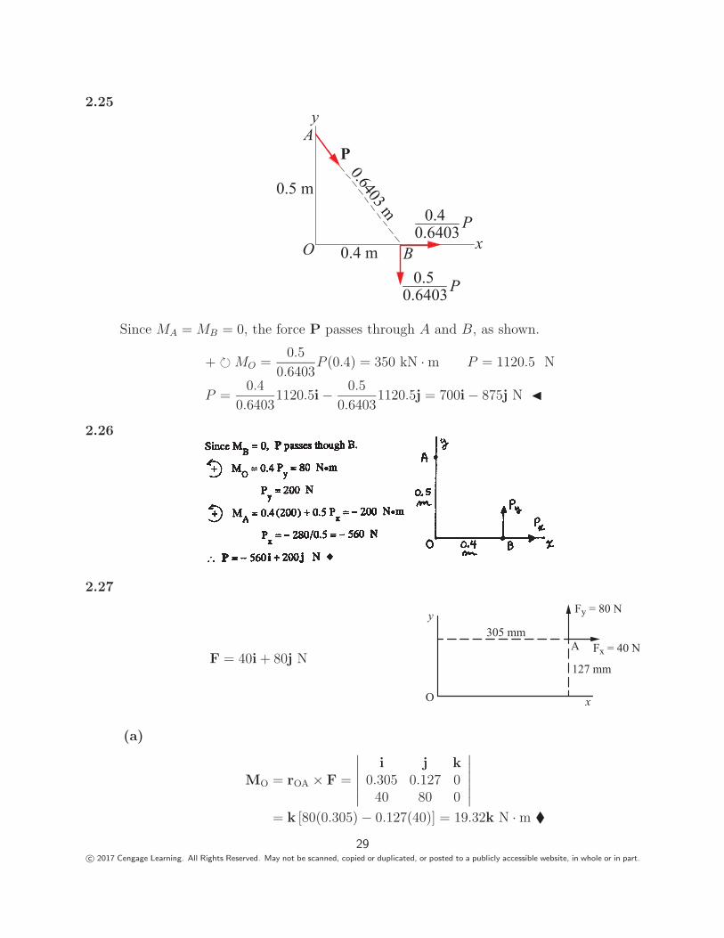
2.25
0.5 m
0.4 m
0.6403 m
P
0.40.6403 P
0.64030.5 P
y
x
A
BO
Since MA = MB = 0, the force P passes through A and B, as shown.
+ � MO =0.5
0.6403P (0.4) = 350 kN · m P = 1120.5 N
P =0.4
0.64031120.5i − 0.5
0.64031120.5j = 700i − 875j N �
2.26
2.27
F = 40i + 80j N
O
A
y305 mm
127 mm
Fy = 80 N
Fx = 40 N
x
(a)
MO = rOA × F =
∣∣∣∣∣∣i j k
0.305 0.127 040 80 0
∣∣∣∣∣∣= k [80(0.305) − 0.127(40)] = 19.32k N · m �
29c© 2017 Cengage Learning. All Rights Reserved. May not be scanned, copied or duplicated, or posted to a publicly accessible website, in whole or in part.
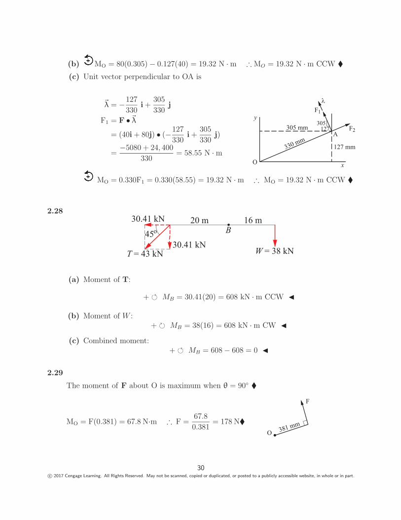
(b) MO = 80(0.305) − 0.127(40) = 19.32 N · m ∴ MO = 19.32 N · m CCW �(c) Unit vector perpendicular to OA is
�λ = −127
330i +
305
330j
F1 = F •�λ
= (40i + 80j) • (−127
330i +
305
330j)
=−5080 + 24, 400
330= 58.55 N · m
MO = 0.330F1 = 0.330(58.55) = 19.32 N · m ∴ MO = 19.32 N · m CCW �
O
A
y305 mm
305127
330 mm127 mm
F1
F2
x
2.2820 m 16 m
45o B
T = 43 kN W = 38 kN
30.41 kN
30.41 kN
(a) Moment of T:
+ � MB = 30.41(20) = 608 kN · m CCW �
(b) Moment of W :+ � MB = 38(16) = 608 kN · m CW �
(c) Combined moment:+ � MB = 608 − 608 = 0 �
2.29
The moment of F about O is maximum when θ = 90◦ �
MO = F(0.381) = 67.8 N·m ∴ F =67.8
0.381= 178 N�
F
O 381 mm
30c© 2017 Cengage Learning. All Rights Reserved. May not be scanned, copied or duplicated, or posted to a publicly accessible website, in whole or in part.
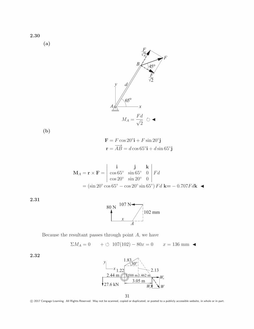
2.30
(a)
d
x
y
A
B
65o
F
45o
2F
2F
MA =Fd√
2� �
(b)
F = F cos 20◦i + F sin 20◦j
r =−→AB = d cos 65◦i + d sin 65◦j
MA = r × F =
∣∣∣∣∣∣i j k
cos 65◦ sin 65◦ 0cos 20◦ sin 20◦ 0
∣∣∣∣∣∣ Fd
= (sin 20◦ cos 65◦ − cos 20◦ sin 65◦) Fd k= − 0.707Fdk �
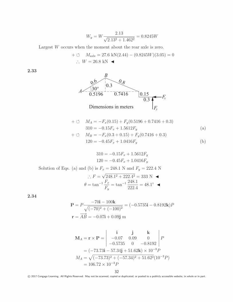
2.31
x
80 N 107 N102 mm
A
Because the resultant passes through point A, we have
ΣMA = 0 + � 107(102) − 80x = 0 x = 136 mm �
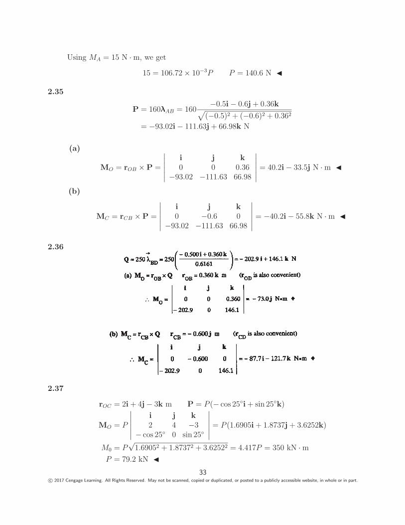
2.32
30o1.83
1.222.44 m
3.05 m
2.131.462 m Wx
Wy
xy
27.6 kN
1.588 m
W
31c© 2017 Cengage Learning. All Rights Reserved. May not be scanned, copied or duplicated, or posted to a publicly accessible website, in whole or in part.
Wy = W2.13√
2.132 + 1.4622= 0.8245W
Largest W occurs when the moment about the rear axle is zero.
+ � Maxle = 27.6 kN(2.44) − (0.8245W )(3.05) = 0
∴ W = 26.8 kN �
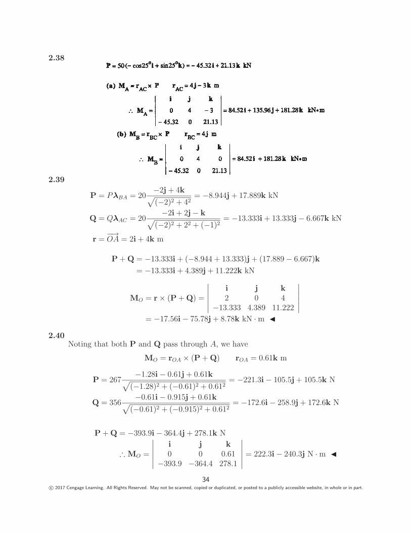
2.33
0.6 0.8
0.150.3
30oA
B
0.3
0.5196 0.7416 Fx
FyDimensions in meters
+ � MA = −Fx(0.15) + Fy(0.5196 + 0.7416 + 0.3)
310 = −0.15Fx + 1.5612Fy (a)
+ � MB = −Fx(0.3 + 0.15) + Fy(0.7416 + 0.3)
120 = −0.45Fx + 1.0416Fy (b)
310 = −0.15Fx + 1.5612Fy
120 = −0.45Fx + 1.0416Fy
Solution of Eqs. (a) and (b) is Fx = 248.1 N and Fy = 222.4 N
∴ F =√
248.12 + 222.42 = 333 N �θ = tan−1 Fx
Fy
= tan−1 248.1
222.4= 48.1◦ �
2.34
P = P−70i − 100k√
(−70)2 + (−100)2= (−0.5735i − 0.8192k)P
r =−→AB = −0.07i + 0.09j m
MA = r × P =
∣∣∣∣∣∣i j k
−0.07 0.09 0−0.5735 0 −0.8192
∣∣∣∣∣∣ P
= (−73.73i − 57.34j + 51.62k) × 10−3P
MA =√
(−73.73)2 + (−57.34)2 + 51.622(10−3P )
= 106.72 × 10⁻³P
32c© 2017 Cengage Learning. All Rights Reserved. May not be scanned, copied or duplicated, or posted to a publicly accessible website, in whole or in part.
Using MA = 15 N · m, we get
15 = 106.72 × 10⁻³P P = 140.6 N �
2.35
P = 160λAB = 160−0.5i − 0.6j + 0.36k√
(−0.5)2 + (−0.6)2 + 0.362
= −93.02i − 111.63j + 66.98k N
(a)
MO = rOB × P =
∣∣∣∣∣∣i j k0 0 0.36
−93.02 −111.63 66.98
∣∣∣∣∣∣ = 40.2i − 33.5j N · m �
(b)
MC = rCB × P =
∣∣∣∣∣∣i j k0 −0.6 0
−93.02 −111.63 66.98
∣∣∣∣∣∣ = −40.2i − 55.8k N · m �
2.36
2.37
rOC = 2i + 4j − 3k m P = P (− cos 25◦i + sin 25◦k)
MO = P
∣∣∣∣∣∣i j k2 4 −3
− cos 25◦ 0 sin 25◦
∣∣∣∣∣∣ = P (1.6905i + 1.8737j + 3.6252k)
M0 = P√
1.69052 + 1.87372 + 3.62522 = 4.417P = 350 kN · mP = 79.2 kN �
33c© 2017 Cengage Learning. All Rights Reserved. May not be scanned, copied or duplicated, or posted to a publicly accessible website, in whole or in part.
2.38
2.39
P = PλBA = 20−2j + 4k√(−2)2 + 42
= −8.944j + 17.889k kN
Q = QλAC = 20−2i + 2j − k√
(−2)2 + 22 + (−1)2= −13.333i + 13.333j − 6.667k kN
r =−→OA = 2i + 4k m
P + Q = −13.333i + (−8.944 + 13.333)j + (17.889 − 6.667)k
= −13.333i + 4.389j + 11.222k kN
MO = r × (P + Q) =
∣∣∣∣∣∣i j k2 0 4
−13.333 4.389 11.222
∣∣∣∣∣∣= −17.56i − 75.78j + 8.78k kN · m �
2.40Noting that both P and Q pass through A, we have
MO = rOA × (P + Q) rOA = 0.61k m
P = 267−1.28i − 0.61j + 0.61k√
(−1.28)2 + (−0.61)2 + 0.612= −221.3i − 105.5j + 105.5k N
Q = 356−0.61i − 0.915j + 0.61k√
(−0.61)2 + (−0.915)2 + 0.612= −172.6i − 258.9j + 172.6k N
P + Q = −393.9i − 364.4j + 278.1k N
∴ MO =
∣∣∣∣∣∣i j k0 0 0.61
−393.9 −364.4 278.1
∣∣∣∣∣∣ = 222.3i − 240.3j N · m �
34c© 2017 Cengage Learning. All Rights Reserved. May not be scanned, copied or duplicated, or posted to a publicly accessible website, in whole or in part.
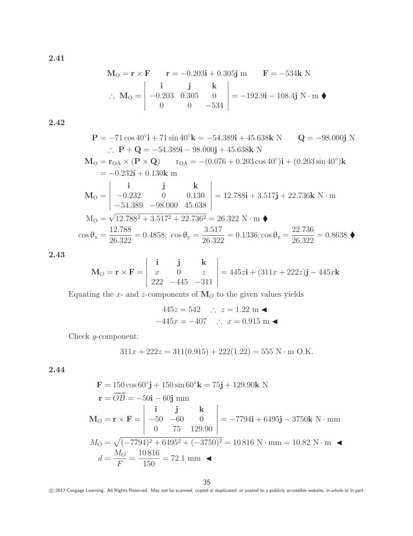
2.41
MO = r × F r = −0.203i + 0.305j m F = −534k N
∴ MO =
∣∣∣∣∣∣i j k
−0.203 0.305 00 0 −534
∣∣∣∣∣∣ = −192.9i − 108.4j N · m �
2.42
P = −71 cos 40◦i + 71 sin 40◦k = −54.389i + 45.638k N Q = −98.000j N
∴ P + Q = −54.389i − 98.000j + 45.638k N
MO = rOA × (P × Q) rOA = −(0.076 + 0.203 cos 40◦)i + (0.203 sin 40◦)k
= −0.232i + 0.130k m
MO =
∣∣∣∣∣∣i j k
−0.232 0 0.130−54.389 −98.000 45.638
∣∣∣∣∣∣ = 12.788i + 3.517j + 22.736k N · m
MO =√
12.7882 + 3.5172 + 22.7362 = 26.322 N · m �
cos θx =12.788
26.322= 0.4858; cos θy =
3.517
26.322= 0.1336; cos θz =
22.736
26.322= 0.8638 �
2.43
MO = r × F =
∣∣∣∣∣∣i j kx 0 z
222 −445 −311
∣∣∣∣∣∣ = 445zi + (311x + 222z)j − 445xk
Equating the x- and z-components of MO to the given values yields
445z = 542 ∴ z = 1.22 m �−445x = −407 ∴ x = 0.915 m �
Check y-component:
311x + 222z = 311(0.915) + 222(1.22) = 555 N · m O.K.
2.44
F = 150 cos 60◦j + 150 sin 60◦k = 75j + 129.90k N
r =−−→OB = −50i − 60j mm
MO = r × F =
∣∣∣∣∣∣i j k
−50 −60 00 75 129.90
∣∣∣∣∣∣ = −7794i + 6495j − 3750k N · mm
MO =√
(−7794)2 + 64952 + (−3750)2 = 10 816 N · mm = 10.82 N · m �
d =MO
F=
10 816
150= 72.1 mm �
35c© 2017 Cengage Learning. All Rights Reserved. May not be scanned, copied or duplicated, or posted to a publicly accessible website, in whole or in part.
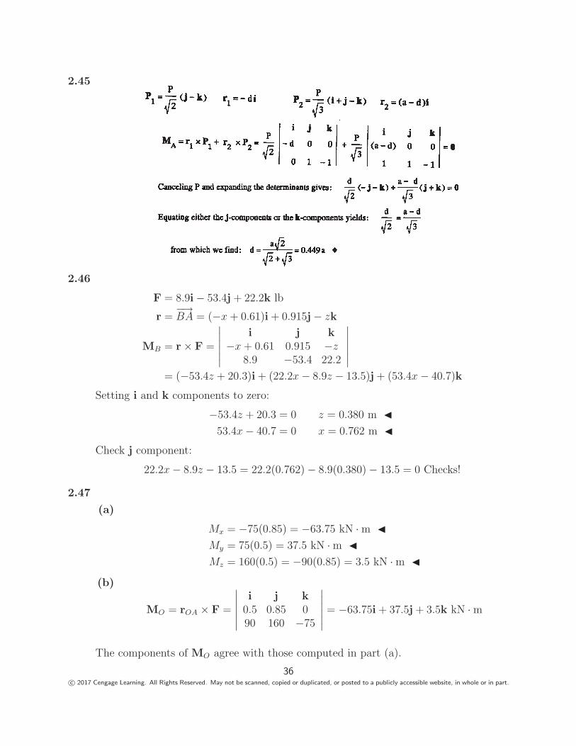
2.45
2.46
F = 8.9i − 53.4j + 22.2k lb
r =−→BA = (−x + 0.61)i + 0.915j − zk
MB = r × F =
∣∣∣∣∣∣i j k
−x + 0.61 0.915 −z8.9 −53.4 22.2
∣∣∣∣∣∣= (−53.4z + 20.3)i + (22.2x − 8.9z − 13.5)j + (53.4x − 40.7)k
Setting i and k components to zero:
−53.4z + 20.3 = 0 z = 0.380 m �53.4x − 40.7 = 0 x = 0.762 m �
Check j component:
22.2x − 8.9z − 13.5 = 22.2(0.762) − 8.9(0.380) − 13.5 = 0 Checks!
2.47
(a)
Mx = −75(0.85) = −63.75 kN · m �My = 75(0.5) = 37.5 kN · m �Mz = 160(0.5) = −90(0.85) = 3.5 kN · m �
(b)
MO = rOA × F =
∣∣∣∣∣∣i j k
0.5 0.85 090 160 −75
∣∣∣∣∣∣ = −63.75i + 37.5j + 3.5k kN · m
The components of MO agree with those computed in part (a).
36c© 2017 Cengage Learning. All Rights Reserved. May not be scanned, copied or duplicated, or posted to a publicly accessible website, in whole or in part.
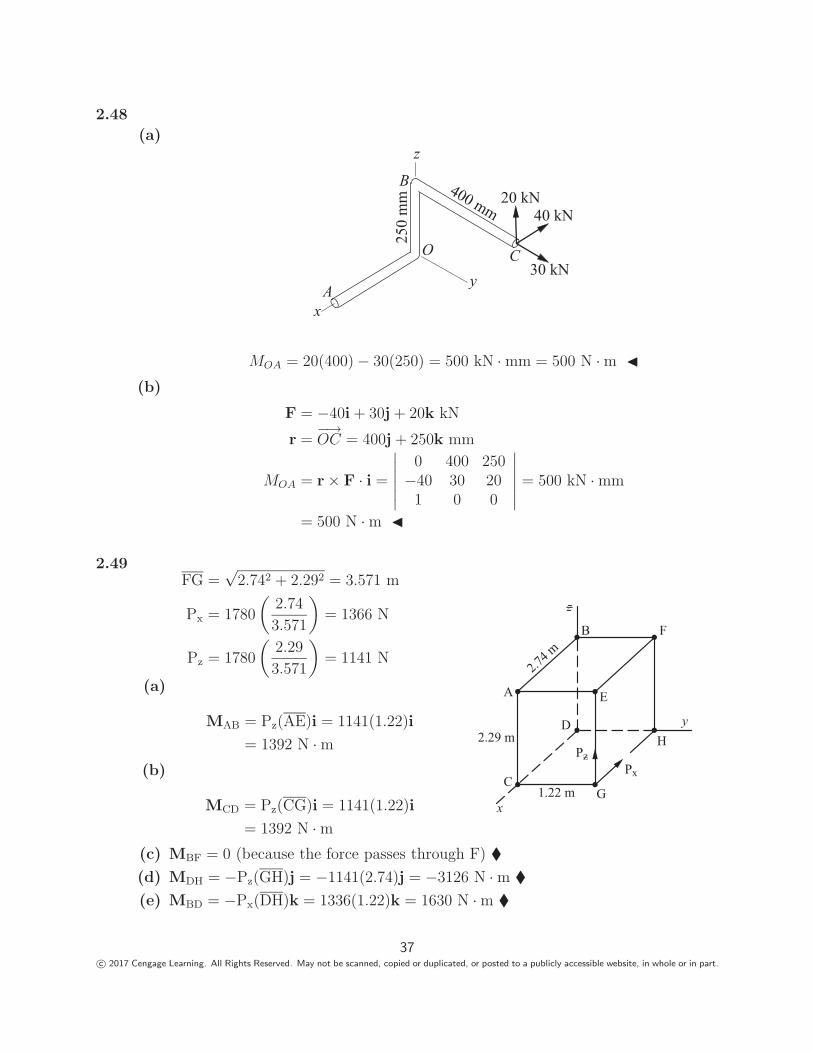
2.48
(a)z
y
xA
O
250
mm 400 mm
20 kN40 kN
30 kN
B
C
MOA = 20(400) − 30(250) = 500 kN · mm = 500 N · m �(b)
F = −40i + 30j + 20k kN
r =−→OC = 400j + 250k mm
MOA = r × F · i =
∣∣∣∣∣∣0 400 250
−40 30 201 0 0
∣∣∣∣∣∣ = 500 kN · mm
= 500 N · m �
2.49FG =
√2.742 + 2.292 = 3.571 m
Px = 1780
(2.74
3.571
)= 1366 N
Pz = 1780
(2.29
3.571
)= 1141 N
(a)
MAB = Pz(AE)i = 1141(1.22)i
= 1392 N · m(b)
MCD = Pz(CG)i = 1141(1.22)i
= 1392 N · mx
C
A
2.74 m
B F
y
E
DH
G1.22 m
2.29 m
Px
Pz
z
(c) MBF = 0 (because the force passes through F) �(d) MDH = −Pz(GH)j = −1141(2.74)j = −3126 N · m �(e) MBD = −Px(DH)k = 1336(1.22)k = 1630 N · m �
37c© 2017 Cengage Learning. All Rights Reserved. May not be scanned, copied or duplicated, or posted to a publicly accessible website, in whole or in part.
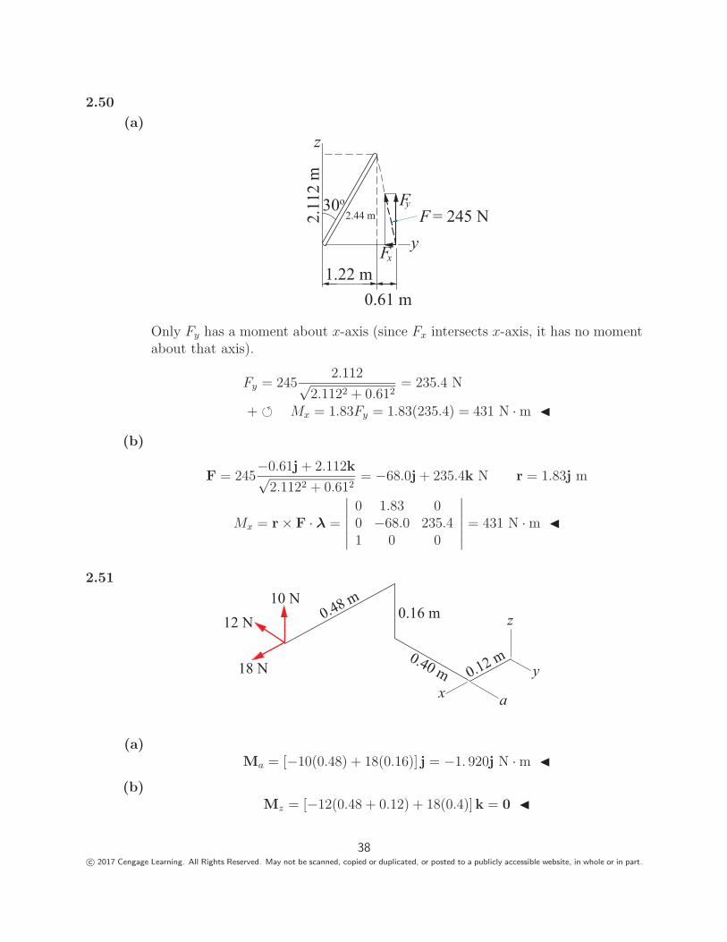
2.50
(a)
2.44 m
1.22 m0.61 m
2.11
2 m
30o
xF
z
y
yFF = 245 N
Only Fy has a moment about x-axis (since Fx intersects x-axis, it has no momentabout that axis).
Fy = 2452.112√
2.1122 + 0.612= 235.4 N
+ � Mx = 1.83Fy = 1.83(235.4) = 431 N · m �
(b)
F = 245−0.61j + 2.112k√
2.1122 + 0.612= −68.0j + 235.4k N r = 1.83j m
Mx = r × F · λ =
∣∣∣∣∣∣0 1.83 00 −68.0 235.41 0 0
∣∣∣∣∣∣ = 431 N · m �
2.51
0.12 m
0.16 m0.48 m
0.40 m
10 N12 N
18 Nx
y
z
a
(a)Ma = [−10(0.48) + 18(0.16)] j = −1. 920j N · m �
(b)Mz = [−12(0.48 + 0.12) + 18(0.4)]k = 0 �
38c© 2017 Cengage Learning. All Rights Reserved. May not be scanned, copied or duplicated, or posted to a publicly accessible website, in whole or in part.
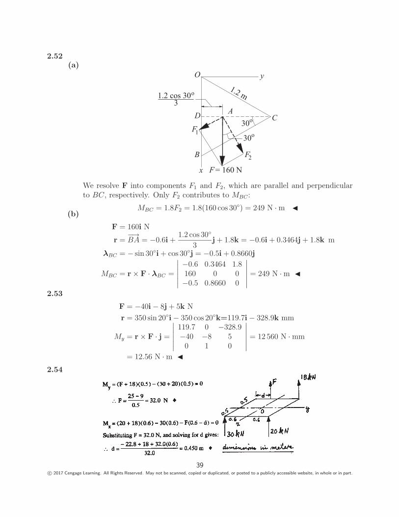
2.52(a)
F30o
30o
F = 160 N
1
F2
x
yO
A
B
CD
1.2 m1.2 cos 30o
3
We resolve F into components F1 and F2, which are parallel and perpendicularto BC, respectively. Only F2 contributes to MBC :
MBC = 1.8F2 = 1.8(160 cos 30◦) = 249 N · m �(b)
F = 160i N
r =−→BA = −0.6i +
1.2 cos 30◦
3j + 1.8k = −0.6i + 0.3464j + 1.8k m
λBC = − sin 30◦i + cos 30◦j = −0.5i + 0.8660j
MBC = r × F · λBC =
∣∣∣∣∣∣−0.6 0.3464 1.8160 0 0−0.5 0.8660 0
∣∣∣∣∣∣ = 249 N · m �
2.53
F = −40i − 8j + 5k N
r = 350 sin 20◦i − 350 cos 20◦k=119.7i − 328.9k mm
My = r × F · j =
∣∣∣∣∣∣119.7 0 −328.9−40 −8 50 1 0
∣∣∣∣∣∣ = 12 560 N · mm
= 12.56 N · m �2.54
39c© 2017 Cengage Learning. All Rights Reserved. May not be scanned, copied or duplicated, or posted to a publicly accessible website, in whole or in part.
2.55
Maa = 133.5(1.22 − y0) + 89(1.83 − y0) − 178y0 = 0 Solving gives: y0 = 0.813 m �Mbb = (89 + 178)x0 − 133.5(1.83 − x0) = 0 Solving gives: x0 = 1.83 m �
2.56With T acting at A, only the component Tz has a moment about the y-axis:My = −1.22Tz.
Tz = TABz
AB= 267
0.915√1.222 + 1.222 + 0.9152
= 125.1 N
∴ My = −1.22(125.1) = −152.6 N · m �
2.57Only the x-component of each force has a moment about the z-axis.
∴ Mz = (P cos 30◦ + Q cos 25◦)0.381
= (142 cos 30◦ + 160 cos 25◦)0.381 = 102.1 N · m �2.58
P = 360−0.42i − 0.81j + 0.54k√
(−0.42)2 + (−0.81)2 + 0.542= −142.6i − 275.0j + 183.4k N
rCA = 0.42i m λCD =0.42i + 0.54k√0.422 + 0.542
= 0.6139i + 0.7894k
MCD = rCA × P · λCD =
∣∣∣∣∣∣0.42 0 0
−142.6 −275.0 183.40.6139 0 0.7894
∣∣∣∣∣∣ = −91.18 N · m
MCD = MCDλCD = −91.18(0.6139i + 0.7894k)
= −56.0i − 72.0k N · m �2.59
Let the 89-N force be Q:
Q = 89�λED = 89
(−0.305j − 0.101k
0.321
)= −84.6j − 28.0k N
P = P�λAF = P
(−0.101i + 0.101k
4√
2
)= P(−0.707i + 0.707k) N
MGB = rBE × Q · �λGB + rBA × P · �λGB = 0
rBE = 0.101i + 0.101k m rBA = 0.101i m �λGB =
(0.305j − 0.101k
0.321
)
MGB =1
0.321
∣∣∣∣∣∣0.101 0 0.101
0 −84.6 −28.00 0.305 −0.101
∣∣∣∣∣∣ +P
0.321
∣∣∣∣∣∣0.101 0 0−0.707 0 0.707
0 0.305 −0.101
∣∣∣∣∣∣ = 0
Expanding the determinants gives :1.726
0.321+
P
0.321(−0.022) = 0 ∴ P = 78.46 N �
40c© 2017 Cengage Learning. All Rights Reserved. May not be scanned, copied or duplicated, or posted to a publicly accessible website, in whole or in part.
2.60
MBC = rBA × F · λBC
rBA = 1.52i F = F−0.915i + 0.915j − 0.915k√
(−0.915)2 + 0.9152 + (−0.915)2= 0.5774F (−i + j − k)
λBC =1.22j − 0.610k√1.222 + (−0.610)2
= 0.8944j − 0.4472k
MBC = rBA × F · λBC = 0.5774F
∣∣∣∣∣∣1.52 0 0−1 1 −10 0.8944 −0.4472
∣∣∣∣∣∣ = 0.315F
MBC = 203 N · m 0.315F = 203 N · m F = 644 N �
2.61The unit vector perpendicular to plane ABC is
λ =
−→AB ×−→
AC∣∣∣−→AB ×−→AC
∣∣∣−→AB = (0.3i − 0.5k)
−→AC = (0.4j − 0.5k) m
−→AB ×−→
AC =
∣∣∣∣∣∣i j k
0.3 0 −0.50 0.4 −0.5
∣∣∣∣∣∣ = 0.2i + 0.15j + 0.12k
F = Fλ = 2000.2i + 0.15j + 0.12k√0.22 + 0.152 + 0.122
= 144.24i + 108.18j + 86.55k N · m
Mx =−→OA × F · i =
∣∣∣∣∣∣0 0 0.5
144.24 108.18 86.551 0 0
∣∣∣∣∣∣ = −54.1 N · m
|Mx| = 54.1 N · m �
2.62
P = 1000�λCE = 1000
(−0.915i + 0.61j − 2.13k√
5.746
)N �λAD =
−0.915i + 1.83j + 2.13k√8.732
(a) r = rAC = 1.83j + 2.13k m
MAD = rAC × P · �λAD =1000√
5.746√
8.732
∣∣∣∣∣∣0 1.83 2.13
−0.915 0.61 −2.13−0.915 1.83 2.13
∣∣∣∣∣∣=
1000√5.746
√8.732
(4.755) = 672 N · m �
41c© 2017 Cengage Learning. All Rights Reserved. May not be scanned, copied or duplicated, or posted to a publicly accessible website, in whole or in part.
(b) r = rDC = 0.915i m
MAD = rDC × P · �λAD =1000√
5.746√
8.732
∣∣∣∣∣∣0.915 0 0−0.915 0.61 −2.13−0.915 1.83 2.13
∣∣∣∣∣∣=
1000√5.746
√8.732
(4.755) = 672 N · m �
2.63Equating moments about the x- and y- axis:
2670(0.46) + 1780(0.61) + 890(1.22) = 5340y y = 0.637 m �−2670(0.915) − 890(0.915) = −5340x x = 0.61 m �
2.64
2.65
42c© 2017 Cengage Learning. All Rights Reserved. May not be scanned, copied or duplicated, or posted to a publicly accessible website, in whole or in part.
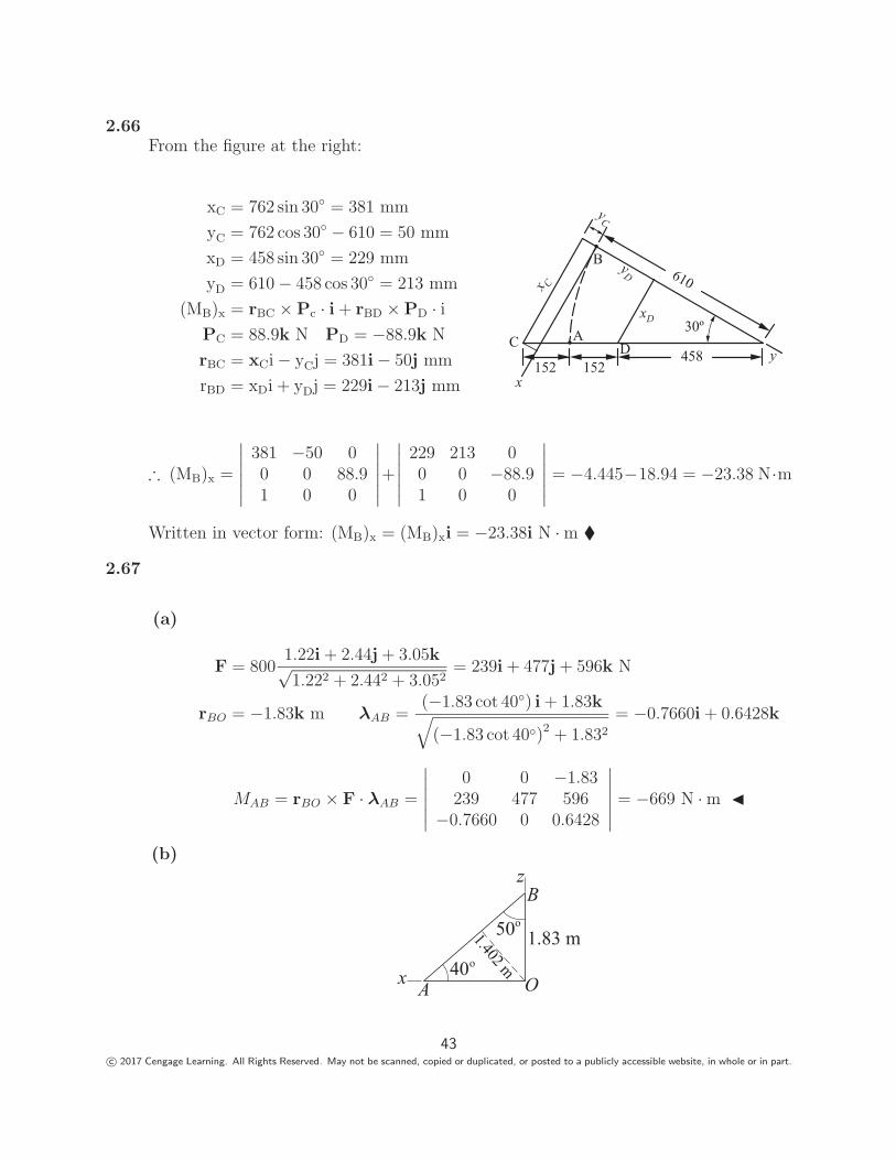
2.66From the figure at the right:
xC = 762 sin 30◦ = 381 mm
yC = 762 cos 30◦ − 610 = 50 mm
xD = 458 sin 30◦ = 229 mm
yD = 610 − 458 cos 30◦ = 213 mm
(MB)x = rBC × Pc · i + rBD × PD · iPC = 88.9k N PD = −88.9k N
rBC = xCi − yCj = 381i − 50j mm
rBD = xDi + yDj = 229i − 213j mm
610
458
30º
152152x
DA
B
C
x C
yC
yD
y
xD
∴ (MB)x =
∣∣∣∣∣∣381 −50 00 0 88.91 0 0
∣∣∣∣∣∣+∣∣∣∣∣∣
229 213 00 0 −88.91 0 0
∣∣∣∣∣∣ = −4.445−18.94 = −23.38 N·m
Written in vector form: (MB)x = (MB)xi = −23.38i N · m �
2.67
(a)
F = 8001.22i + 2.44j + 3.05k√1.222 + 2.442 + 3.052
= 239i + 477j + 596k N
rBO = −1.83k m λAB =(−1.83 cot 40◦) i + 1.83k√(−1.83 cot 40◦)2 + 1.832
= −0.7660i + 0.6428k
MAB = rBO × F · λAB =
∣∣∣∣∣∣0 0 −1.83
239 477 596−0.7660 0 0.6428
∣∣∣∣∣∣ = −669 N · m �
(b)
O40o
50o1.83 m1.402 m
A
B
x
z
43c© 2017 Cengage Learning. All Rights Reserved. May not be scanned, copied or duplicated, or posted to a publicly accessible website, in whole or in part.
Note that only Fy = 477 N has a moment about AB. From trigonometry, themoment arm is d = 1.83 sin 50◦ = 1.402 m.
∴ MAB = −Fyd = −477(1.402) = −669 N · m �
2.68
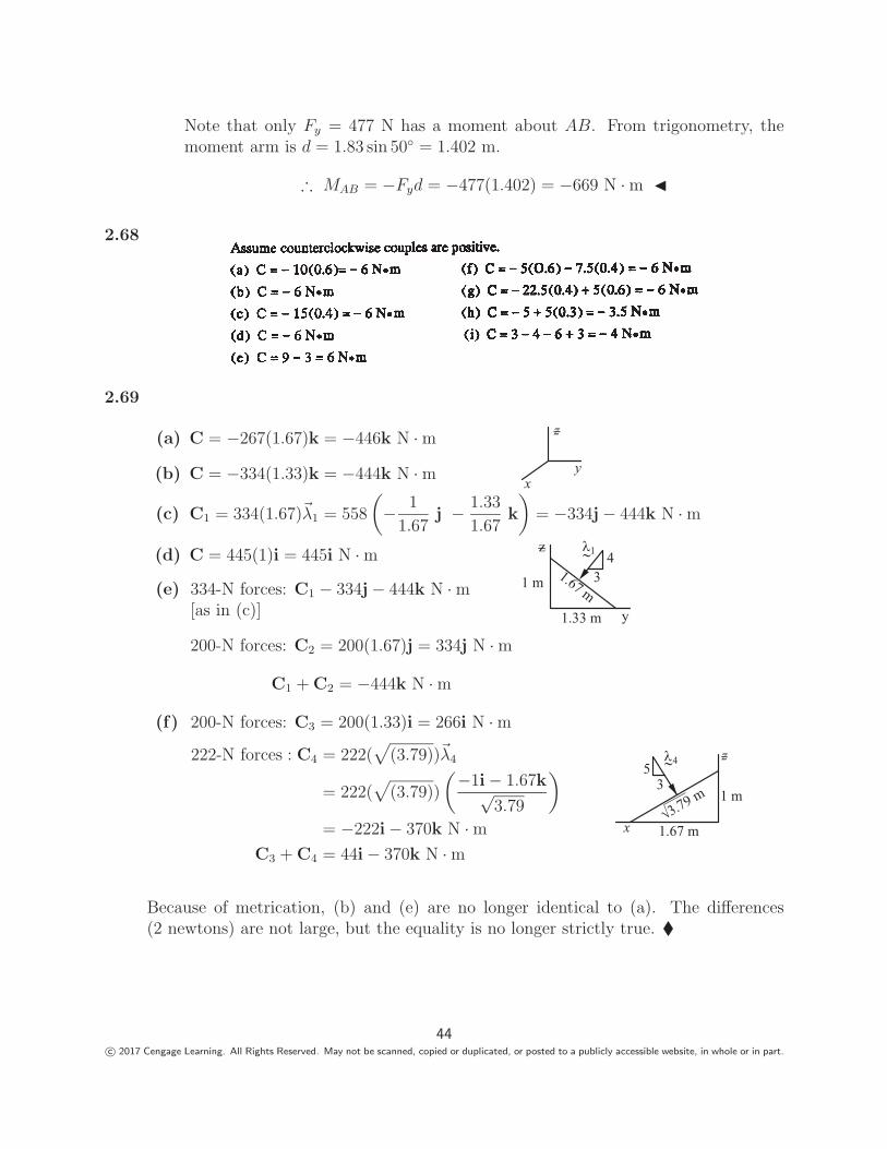
2.69
(a) C = −267(1.67)k = −446k N · m
(b) C = −334(1.33)k = −444k N · m yx
z
(c) C1 = 334(1.67)�λ1 = 558
(− 1
1.67j − 1.33
1.67k
)= −334j − 444k N · m
(d) C = 445(1)i = 445i N · m z
y1.33 m
1 m
431.67 m
1
(e) 334-N forces: C1 − 334j − 444k N · m[as in (c)]
200-N forces: C2 = 200(1.67)j = 334j N · m
C1 + C2 = −444k N · m
(f) 200-N forces: C3 = 200(1.33)i = 266i N · m
222-N forces : C4 = 222(√
(3.79))�λ4
= 222(√
(3.79))
(−1i − 1.67k√
3.79
)
= −222i − 370k N · mC3 + C4 = 44i − 370k N · m
z5
3
x 1.67 m
1 m
4
3.79 m
Because of metrication, (b) and (e) are no longer identical to (a). The differences(2 newtons) are not large, but the equality is no longer strictly true. �
44c© 2017 Cengage Learning. All Rights Reserved. May not be scanned, copied or duplicated, or posted to a publicly accessible website, in whole or in part.
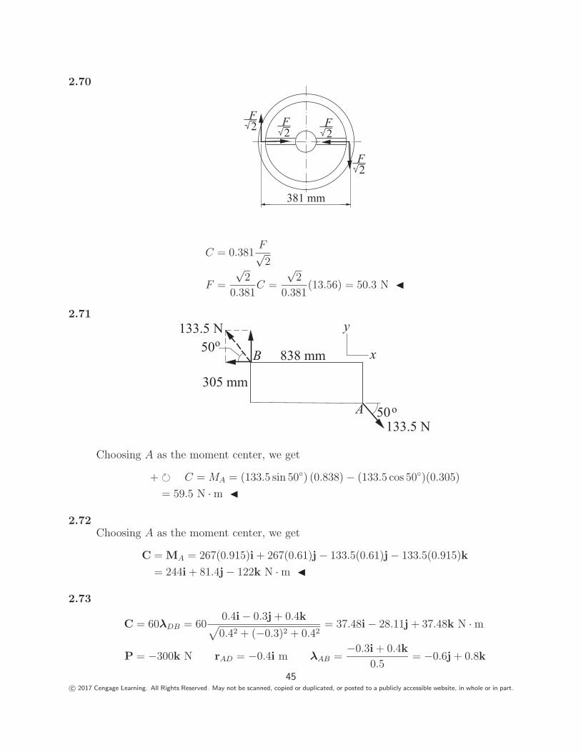
2.70
381 mm
F2
F2
F2
F2
C = 0.381F√2
F =
√2
0.381C =
√2
0.381(13.56) = 50.3 N �
2.71
133.5 N
133.5 N
305 mm
y
x50o
50oA
B 838 mm
Choosing A as the moment center, we get
+ � C = MA = (133.5 sin 50◦) (0.838) − (133.5 cos 50◦)(0.305)
= 59.5 N · m �
2.72Choosing A as the moment center, we get
C = MA = 267(0.915)i + 267(0.61)j − 133.5(0.61)j − 133.5(0.915)k
= 244i + 81.4j − 122k N · m �
2.73
C = 60λDB = 600.4i − 0.3j + 0.4k√0.42 + (−0.3)2 + 0.42
= 37.48i − 28.11j + 37.48k N · m
P = −300k N rAD = −0.4i m λAB =−0.3i + 0.4k
0.5= −0.6j + 0.8k
45c© 2017 Cengage Learning. All Rights Reserved. May not be scanned, copied or duplicated, or posted to a publicly accessible website, in whole or in part.
Moment of the couple:
(MAB)C = C · λAB = −28.11(−0.6) + 37.48(0.8) = 46.85 N · m
Moment of the force:
(MAB)P = rAD × P · λAB =
∣∣∣∣∣∣−0.4 0 0
0 0 −3000 −0.6 0.8
∣∣∣∣∣∣ = 72.0 N · m
Combined moment:
MAB = (MAB)C + (MAB)P = 46.85 + 72.0 = 118.9 N · m �
*2.74C1 = −22.6 N · m C2 = 15.8 N · m
Identify the three points at the corners of the triangle:
A(229 mm, 76.2 mm, 152.5 mm); B(76.2 mm, 178 mm, 152.5 mm);
C(229 mm, 178 mm, 50.8 mm)
C3 = 24.8�λ N · m where �λ is the unit vector that is perpendicular to triangle ABC,with its sense consistent with the sense of C3.
�λ =
−→AC ×−→
AB∣∣∣−→AC ×−→AB
∣∣∣ where−→AC = 102j − 102k mm and
−→AB = −153i + 102j mm
−→AC ×−→
AB =
∣∣∣∣∣∣i j k0 102 −102
−153 102 0
∣∣∣∣∣∣ = 10, 404i + 15, 606j + 15, 606k mm2
∴ �λ =10, 404i + 15, 606j + 15, 606k
24, 400= 0.426i + 0.640j + 0.640k
C3 = 24.8(0.426i + 0.640j + 0.640k) = 10.56i + 15.87j + 15.87k N · m∴ CR = C1 + C2 + C3 = −22.6i + 15.8k + (10.56i + 15.87j + 15.87k) N · m
= −12.04i + 15.87j + 31.67k N · m �
2.75Moment of a couple is the same about any point. Choosing B as the moment center,we have
F = −30i kN rBA = −1.8j − 1.2k m
C = MB = rBA × F =
∣∣∣∣∣∣i j k0 −1.8 −1.2
−30 0 0
∣∣∣∣∣∣ = 36.0j − 54.0k kN · m �
46c© 2017 Cengage Learning. All Rights Reserved. May not be scanned, copied or duplicated, or posted to a publicly accessible website, in whole or in part.
2.76Moment of a couple is the same about any point. Choosing B as the moment center,we have
rBA = 180i − bj mm
Cz = (MB)z = rBA × F · k=
∣∣∣∣∣∣180 −b 0150 −90 600 0 1
∣∣∣∣∣∣ = 150b − 16 200 kN · mm
∴ 150b − 16 200 = 0 b = 108.0 mm �
2.77
C = MA = 89(0.610)i − 356(0.406)j + 222(0.610)k
= 54.3i − 145j + 135k N · m �
2.78
C = −488 cos 30◦i − 488 sin 30◦j = −422.6i − 244.0j N · m�λCD = − cos 30◦i − sin 30◦ cos 40◦j + sin 30◦ sin 40◦k = −0.8660i − 0.3830j + 0.3214k
∴ MCD = C • �λCD = (−422.6)(−0.8660) + (−244.0)(−0.3830) = 459 N · m �
2.79
�λDC = sin 30◦ sin 40◦i − sin 30◦ cos 40◦j + cos 30◦k = 0.3214i − 0.3830j + 0.8660k
(a) C = 70.5 �λDC = 22.66i − 27.00j + 61.05k N · m �(b) Mz = Cz = 61.05k N · m �
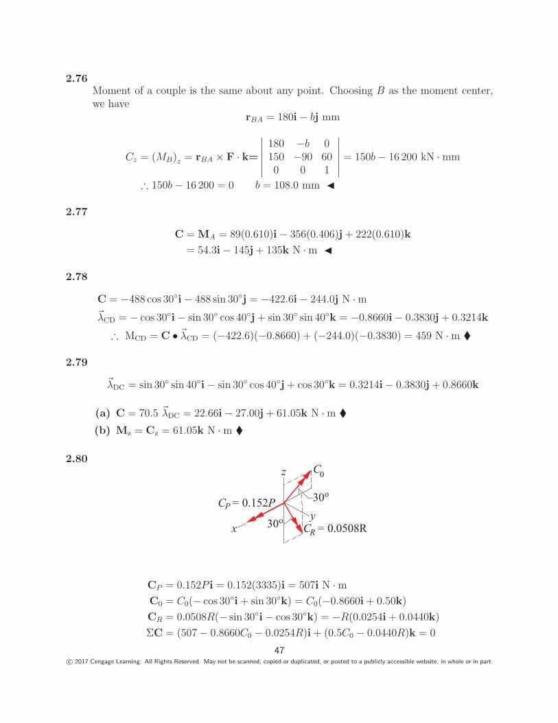
2.80
xy
z
30o
30o
C0
C = 0.0508RR
C = 0.152PP
CP = 0.152P i = 0.152(3335)i = 507i N · mC0 = C0(− cos 30◦i + sin 30◦k) = C0(−0.8660i + 0.50k)
CR = 0.0508R(− sin 30◦i − cos 30◦k) = −R(0.0254i + 0.0440k)
ΣC = (507 − 0.8660C0 − 0.0254R)i + (0.5C0 − 0.0440R)k = 0
47c© 2017 Cengage Learning. All Rights Reserved. May not be scanned, copied or duplicated, or posted to a publicly accessible website, in whole or in part.
Equating like components:
507 − 0.8660C0 − 0.0254R = 0
0.5C0 − 0.0440R = 0
The solution is:R = 4990 N � C0 = 439.1 N · m �
2.81
x
y
zC
1.8 N m
.
.
1.8 N m.
3 N m
25o
The system consists of the four couples shown, where
C = 0.36F (i cos θ + k sin θ) N · mΣC = −2(1.8)k + 3(−i cos 25◦ + k sin 25◦) + 0.36F (i cos θ + k sin θ) = 0
Equating like components:
−3 cos 25◦ + 0.36F cos θ = 0
−3.6 + 3 sin 25◦ + 0.36F sin θ = 0
F cos θ =3 cos 25◦
0.36= 7.553
F sin θ =3.6 − 3 sin 25◦
0.36= 6.478
tan θ =6.478
7.553= 0.8577 θ = 40.6◦ �
F =√
7.5532 + 6.4782 = 9.95 N �
2.82
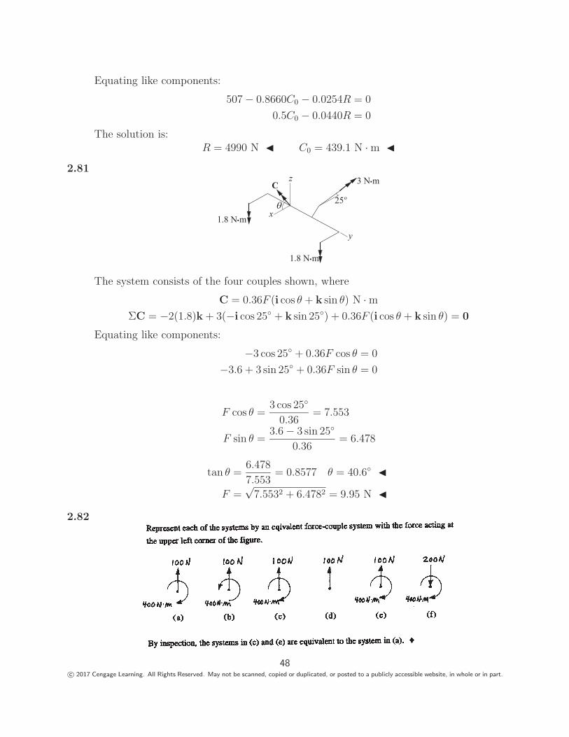
48c© 2017 Cengage Learning. All Rights Reserved. May not be scanned, copied or duplicated, or posted to a publicly accessible website, in whole or in part.
2.83
Originalsystem
(i) Equivalent system with force at B.
(i) Equivalent system: one force at B and one force at C.
A
152 mm
55.9 mm 10.1 N.m 181 N
181 N 181 N
66.7 N 66.7 N 247.7 N
66.7 N CT = 66.7(0.152)= 10.1 N.m
10.1/0.0559 = 181 N
B
C
A
B
C
(a) Fig. (i): A 66.7-N force acting to the left at B, and a 10.1 N·m clockwise couple. �(b) Fig. (ii): A 247.7-N force acting to the left at B, and a 181-N force acting to the
right at C. �
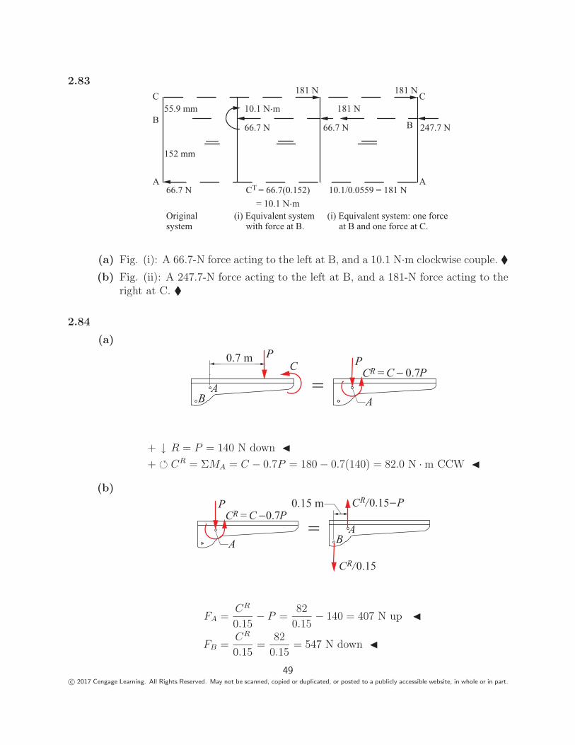
2.84
(a)
AB
0.7 m PC
A
PCR
== C 0.7P
+ ↓ R = P = 140 N down �+ � CR = ΣMA = C − 0.7P = 180 − 0.7(140) = 82.0 N · m CCW �
(b)
A
PCR = C 0.7P
AB
0.15 m
=C /0.15R
C /0.15R
P
FA =CR
0.15− P =
82
0.15− 140 = 407 N up �
FB =CR
0.15=
82
0.15= 547 N down �
49c© 2017 Cengage Learning. All Rights Reserved. May not be scanned, copied or duplicated, or posted to a publicly accessible website, in whole or in part.
2.85
↓ R = ΣF = 15 − 20 + 20 = 15 kN �+ � CR = ΣMA = 15(3) − 20(6) + 20(8) = 85 kN · m �
2.86
R = −400j + 222(i sin 30◦ − j cos 30◦) = 111i − 592j lb �+ � CR = 400(0.229) − 222(0.305) = 83.8 N · m CR = 83.8k N · m �
2.87The resultant force R equals V .
∴ V = R = 6320 N �
CR = ΣMD = 0 : 0.508V − 0.254H − C = 0
0.508 (6320) − 0.254H − 1020 = 0 H = 8620 N �
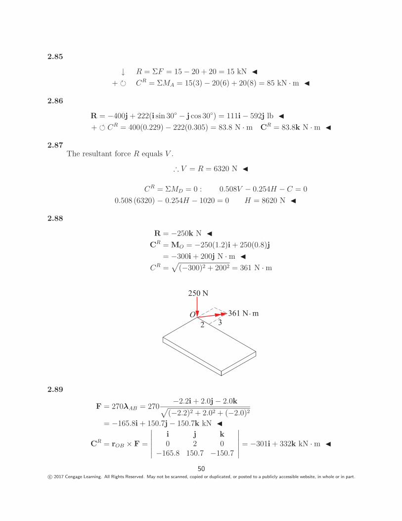
2.88
R = −250k N �CR = MO = −250(1.2)i + 250(0.8)j
= −300i + 200j N · m �CR =
√(−300)2 + 2002 = 361 N · m
O
250 N
2 3361 N m.
2.89
F = 270λAB = 270−2.2i + 2.0j − 2.0k√
(−2.2)2 + 2.02 + (−2.0)2
= −165.8i + 150.7j − 150.7k kN �
CR = rOB × F =
∣∣∣∣∣∣i j k0 2 0
−165.8 150.7 −150.7
∣∣∣∣∣∣ = −301i + 332k kN · m �
50c© 2017 Cengage Learning. All Rights Reserved. May not be scanned, copied or duplicated, or posted to a publicly accessible website, in whole or in part.
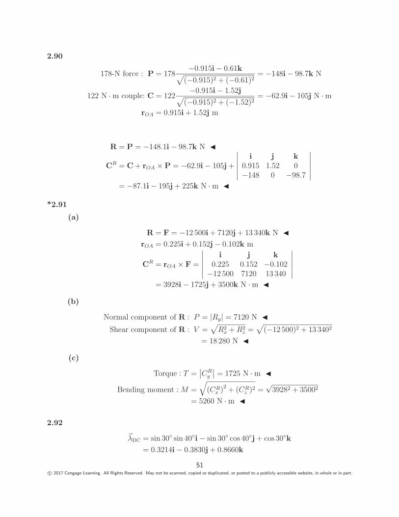
2.90
178-N force : P = 178−0.915i − 0.61k√
(−0.915)2 + (−0.61)2= −148i − 98.7k N
122 N · m couple: C = 122−0.915i − 1.52j√
(−0.915)2 + (−1.52)2= −62.9i − 105j N · m
rOA = 0.915i + 1.52j m
R = P = −148.1i − 98.7k N �
CR = C + rOA × P = −62.9i − 105j +
∣∣∣∣∣∣i j k
0.915 1.52 0−148 0 −98.7
∣∣∣∣∣∣= −87.1i − 195j + 225k N · m �
*2.91
(a)
R = F = −12 500i + 7120j + 13 340k N �rOA = 0.225i + 0.152j − 0.102k m
CR = rOA × F =
∣∣∣∣∣∣i j k
0.225 0.152 −0.102−12 500 7120 13 340
∣∣∣∣∣∣= 3928i − 1725j + 3500k N · m �
(b)
Normal component of R : P = |Ry| = 7120 N �Shear component of R : V =
√R2
x + R2z =
√(−12 500)2 + 13 3402
= 18 280 N �
(c)
Torque : T =∣∣CR
y
∣∣ = 1725 N · m �
Bending moment : M =
√(CR
x )2 + (CRz )2 =
√39282 + 35002
= 5260 N · m �
2.92
�λDC = sin 30◦ sin 40◦i − sin 30◦ cos 40◦j + cos 30◦k
= 0.3214i − 0.3830j + 0.8660k
51c© 2017 Cengage Learning. All Rights Reserved. May not be scanned, copied or duplicated, or posted to a publicly accessible website, in whole or in part.
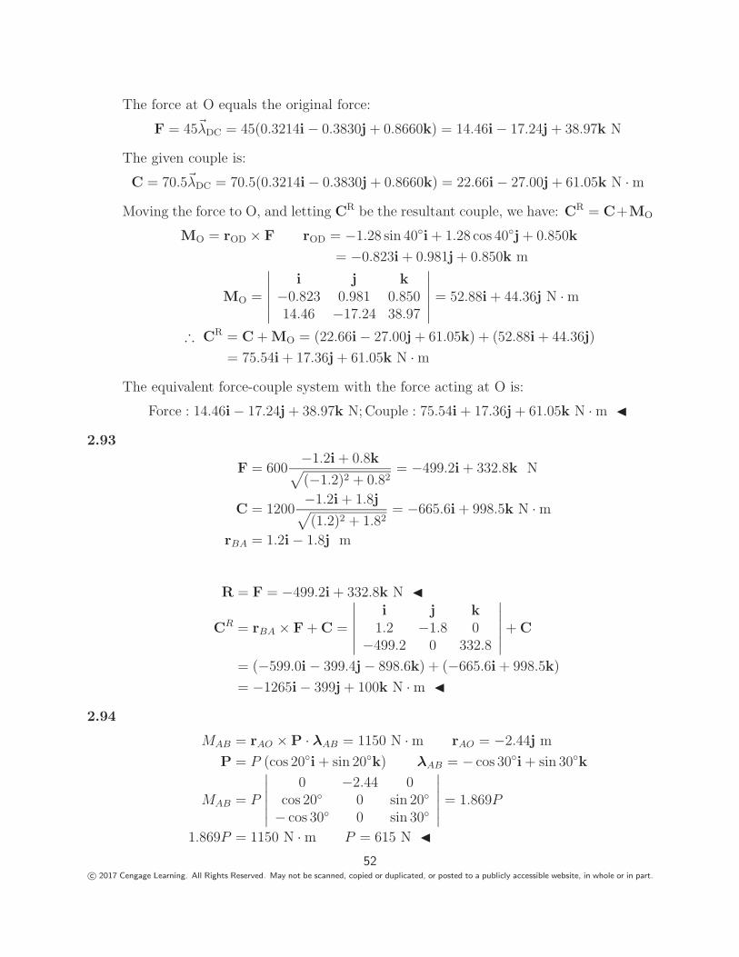
The force at O equals the original force:
F = 45�λDC = 45(0.3214i − 0.3830j + 0.8660k) = 14.46i − 17.24j + 38.97k N
The given couple is:
C = 70.5�λDC = 70.5(0.3214i − 0.3830j + 0.8660k) = 22.66i − 27.00j + 61.05k N · m
Moving the force to O, and letting CR be the resultant couple, we have: CR = C+MO
MO = rOD × F rOD = −1.28 sin 40◦i + 1.28 cos 40◦j + 0.850k
= −0.823i + 0.981j + 0.850k m
MO =
∣∣∣∣∣∣i j k
−0.823 0.981 0.85014.46 −17.24 38.97
∣∣∣∣∣∣ = 52.88i + 44.36j N · m
∴ CR = C + MO = (22.66i − 27.00j + 61.05k) + (52.88i + 44.36j)
= 75.54i + 17.36j + 61.05k N · m
The equivalent force-couple system with the force acting at O is:
Force : 14.46i − 17.24j + 38.97k N; Couple : 75.54i + 17.36j + 61.05k N · m �
2.93
F = 600−1.2i + 0.8k√(−1.2)2 + 0.82
= −499.2i + 332.8k N
C = 1200−1.2i + 1.8j√(1.2)2 + 1.82
= −665.6i + 998.5k N · m
rBA = 1.2i − 1.8j m
R = F = −499.2i + 332.8k N �
CR = rBA × F + C =
∣∣∣∣∣∣i j k
1.2 −1.8 0−499.2 0 332.8
∣∣∣∣∣∣ + C
= (−599.0i − 399.4j − 898.6k) + (−665.6i + 998.5k)
= −1265i − 399j + 100k N · m �
2.94
MAB = rAO × P · λAB = 1150 N · m rAO = −2.44j m
P = P (cos 20◦i + sin 20◦k) λAB = − cos 30◦i + sin 30◦k
MAB = P
∣∣∣∣∣∣0 −2.44 0
cos 20◦ 0 sin 20◦
− cos 30◦ 0 sin 30◦
∣∣∣∣∣∣ = 1.869P
1.869P = 1150 N · m P = 615 N �52
c© 2017 Cengage Learning. All Rights Reserved. May not be scanned, copied or duplicated, or posted to a publicly accessible website, in whole or in part.
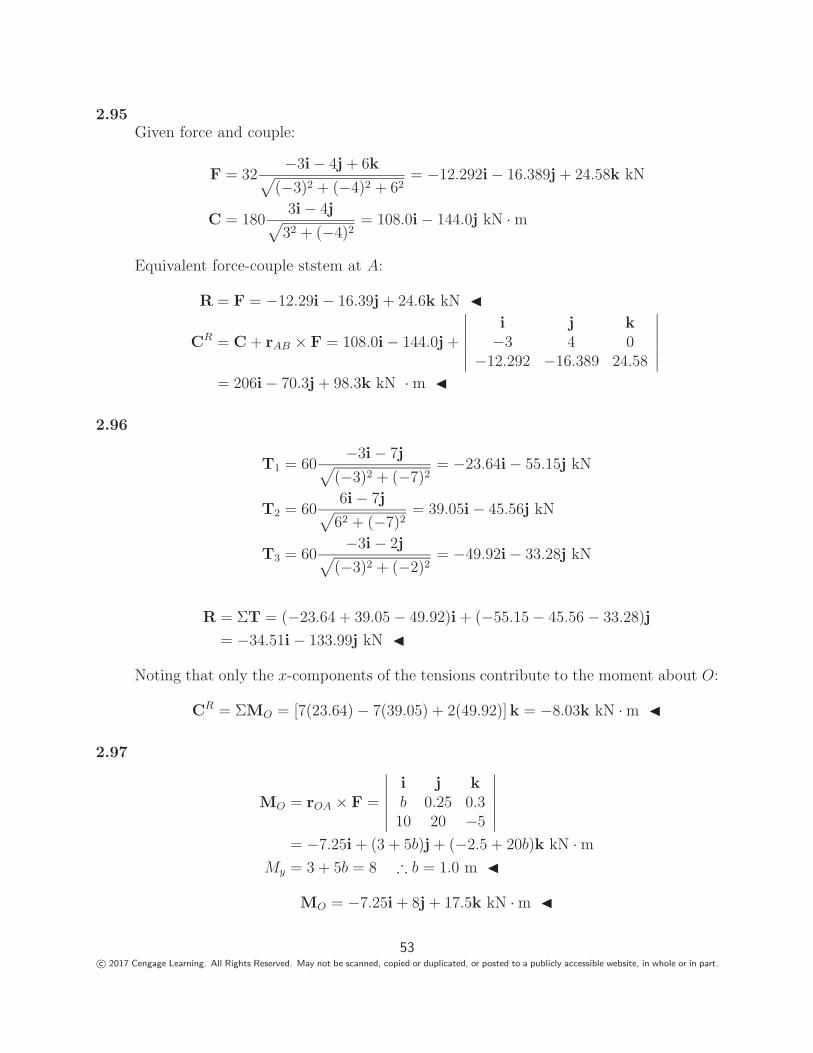
2.95Given force and couple:
F = 32−3i − 4j + 6k√
(−3)2 + (−4)2 + 62= −12.292i − 16.389j + 24.58k kN
C = 1803i − 4j√
32 + (−4)2= 108.0i − 144.0j kN · m
Equivalent force-couple ststem at A:
R = F = −12.29i − 16.39j + 24.6k kN �
CR = C + rAB × F = 108.0i − 144.0j +
∣∣∣∣∣∣i j k−3 4 0
−12.292 −16.389 24.58
∣∣∣∣∣∣= 206i − 70.3j + 98.3k kN · m �
2.96
T1 = 60−3i − 7j√
(−3)2 + (−7)2= −23.64i − 55.15j kN
T2 = 606i − 7j√
62 + (−7)2= 39.05i − 45.56j kN
T3 = 60−3i − 2j√
(−3)2 + (−2)2= −49.92i − 33.28j kN
R = ΣT = (−23.64 + 39.05 − 49.92)i + (−55.15 − 45.56 − 33.28)j
= −34.51i − 133.99j kN �
Noting that only the x-components of the tensions contribute to the moment about O:
CR = ΣMO = [7(23.64) − 7(39.05) + 2(49.92)]k = −8.03k kN · m �
2.97
MO = rOA × F =
∣∣∣∣∣∣i j kb 0.25 0.310 20 −5
∣∣∣∣∣∣= −7.25i + (3 + 5b)j + (−2.5 + 20b)k kN · m
My = 3 + 5b = 8 ∴ b = 1.0 m �
MO = −7.25i + 8j + 17.5k kN · m �
53c© 2017 Cengage Learning. All Rights Reserved. May not be scanned, copied or duplicated, or posted to a publicly accessible website, in whole or in part.
2.98
MCD = rCA × P • �λCD = 5.65 N · m
rCA = 0.1524i − 0.0508j m P = P�λAB = P
(−0.0762i − 0.0508j + 0.1270k√
0.025
)N
�λCD =−0.1016j + 0.1270k√
0.026
Using the determinant form of the scalar triple product:
MCD =P√
0.025√
0.026
∣∣∣∣∣∣0.1524 −0.0508 0−0.0762 −0.0508 0.1270
0 −0.1016 0.1270
∣∣∣∣∣∣=
P√0.025
√0.026
[0.1524(−0.00645 + 0.0129) + 0.0508(0.00968)] = 5.65 N · m
Solving for P gives: P =5.65
√0.025
√0.026
0.000492= 294 N �
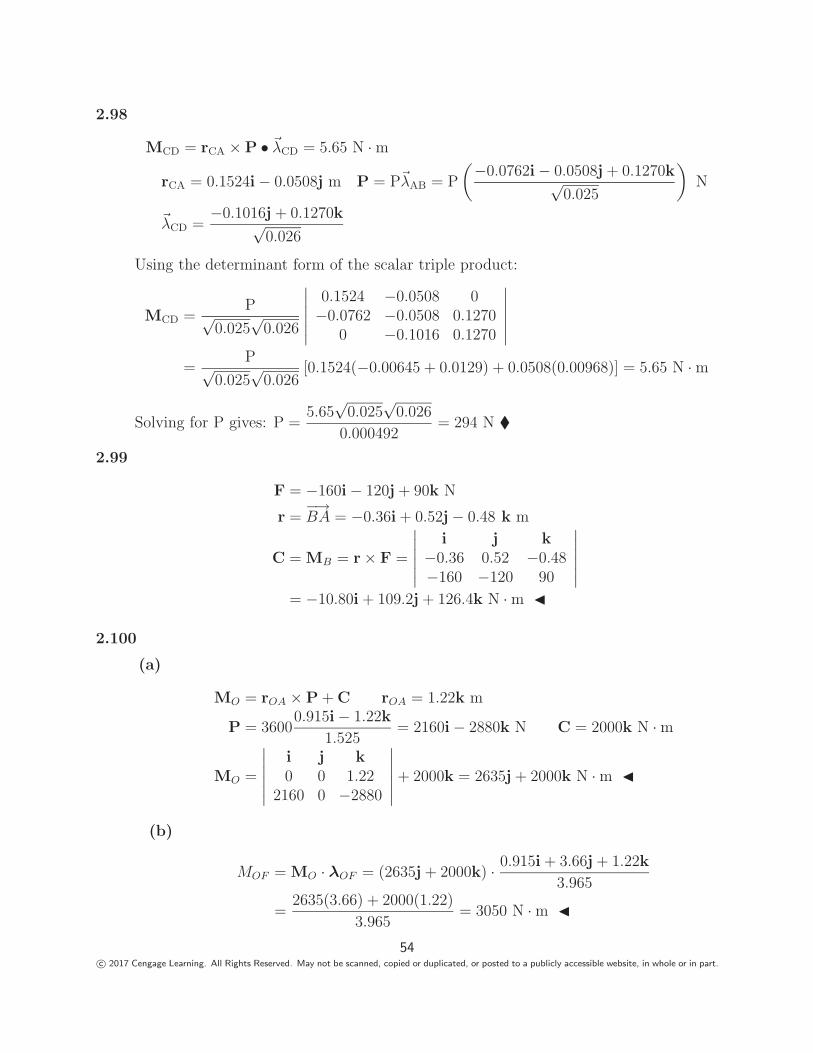
2.99
F = −160i − 120j + 90k N
r =−→BA = −0.36i + 0.52j − 0.48 k m
C = MB = r × F =
∣∣∣∣∣∣i j k
−0.36 0.52 −0.48−160 −120 90
∣∣∣∣∣∣= −10.80i + 109.2j + 126.4k N · m �
2.100
(a)
MO = rOA × P + C rOA = 1.22k m
P = 36000.915i − 1.22k
1.525= 2160i − 2880k N C = 2000k N · m
MO =
∣∣∣∣∣∣i j k0 0 1.22
2160 0 −2880
∣∣∣∣∣∣ + 2000k = 2635j + 2000k N · m �
(b)
MOF = MO · λOF = (2635j + 2000k) · 0.915i + 3.66j + 1.22k
3.965
=2635(3.66) + 2000(1.22)
3.965= 3050 N · m �
54c© 2017 Cengage Learning. All Rights Reserved. May not be scanned, copied or duplicated, or posted to a publicly accessible website, in whole or in part.
2.101
Rx = ΣFx = T1 sin 45◦ − T3 sin 30◦ = 0
Ry = ΣFy = T1 cos 45◦ + T3 cos 30◦ + 1110 = 3330
The solution isT1 = 1150 N � T3 = 1625 N �
2.102
x
y
AdC
FCT
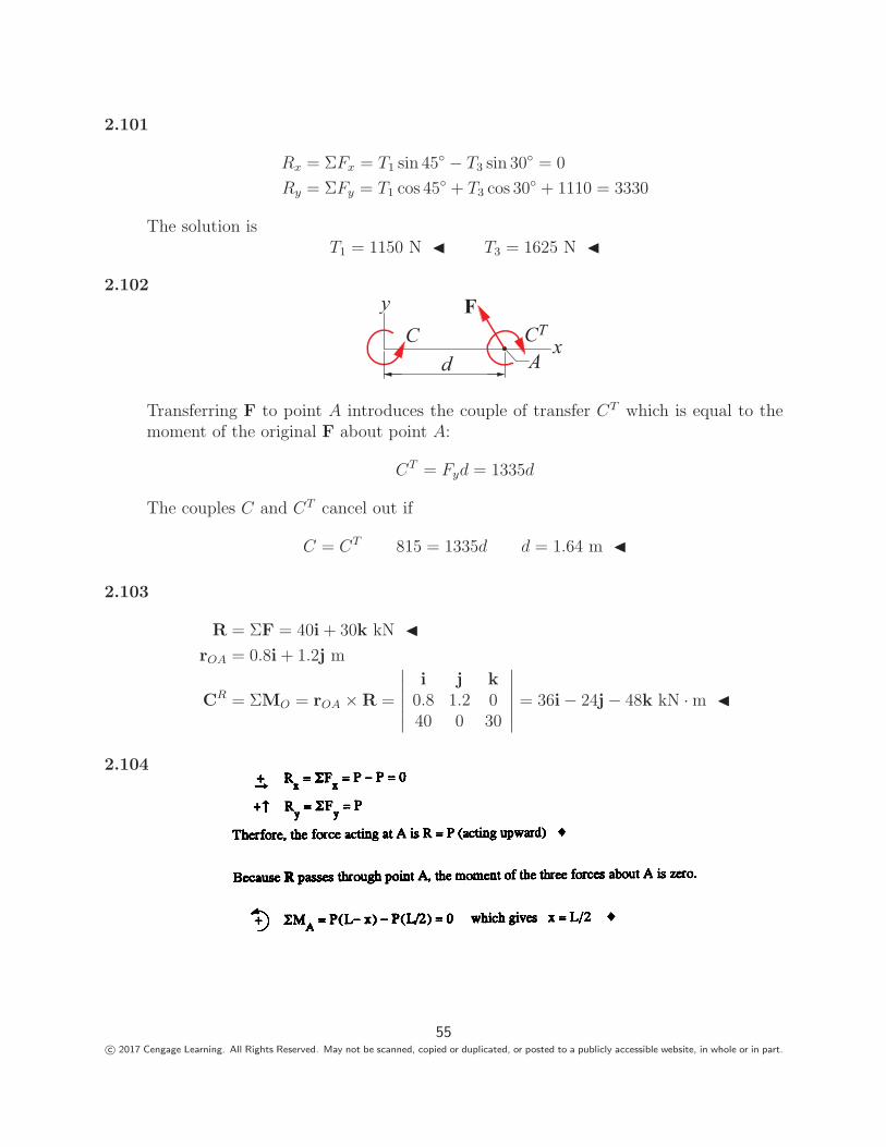
Transferring F to point A introduces the couple of transfer CT which is equal to themoment of the original F about point A:
CT = Fyd = 1335d
The couples C and CT cancel out if
C = CT 815 = 1335d d = 1.64 m �
2.103
R = ΣF = 40i + 30k kN �rOA = 0.8i + 1.2j m
CR = ΣMO = rOA × R =
∣∣∣∣∣∣i j k
0.8 1.2 040 0 30
∣∣∣∣∣∣ = 36i − 24j − 48k kN · m �
2.104
55c© 2017 Cengage Learning. All Rights Reserved. May not be scanned, copied or duplicated, or posted to a publicly accessible website, in whole or in part.
2.105
Because the resultant force passes through Oand there is no resultant couple, the combinedmoment of the two forces about O is zero.
30º60º
O
0.8P
0.6P
446 N102 mm 12
7 mm
1070
ΣMO = 1070(0.102 cos 30◦) + 446(0.102 sin 30◦) − 0.8P(0.127 cos 60◦)
− 0.6P(0.127 sin 60◦) = 0
Solving for P gives: P = 1004 N �
2.106−→BA = −0.91i − 0.915 cos 20◦j + (1.22 − 0.915 sin 20◦)k = 0.91i − 0.860j + 0.907k N−→CA = −0.61i − 0.860j + 0.907k N
T1 = 133�λBA = 133
(0.91i − 0.860j + 0.907k
1.546
)= −78.3i − 74.0j + 78.0k N
T2 = 400�λCA = 400
(−0.61i − 0.860j + 0.907k
1.391
)= 175i − 247j + 261k N
R = T1 + T2 = 96.7i − 321j + 339k N
∴ R =√
0.1502 + (−1.174)2 + 1.2392 = 477 N �
2.107
F = −1780i + 1335j + 1110k N
C = C−0.915j + 1.22k
1.525= C(−0.6j + 0.8k)
rDA = 0.915j ft λDE = −0.6i + 0.8k
(MDE)P = rDA × P · λDE =
∣∣∣∣∣∣0 0.915 0
−1780 1335 1110−0.6 0 0.8
∣∣∣∣∣∣ = 694 N · m
(MDE)C = C · λDE = C(−0.6j + 0.8k) · (−0.6i + 0.8k) = 0.64C
MDE = (MDE)P + (MDE)C = 1625 N · m694 + 0.64C = 1625 C = 1455 N · m �
56c© 2017 Cengage Learning. All Rights Reserved. May not be scanned, copied or duplicated, or posted to a publicly accessible website, in whole or in part.
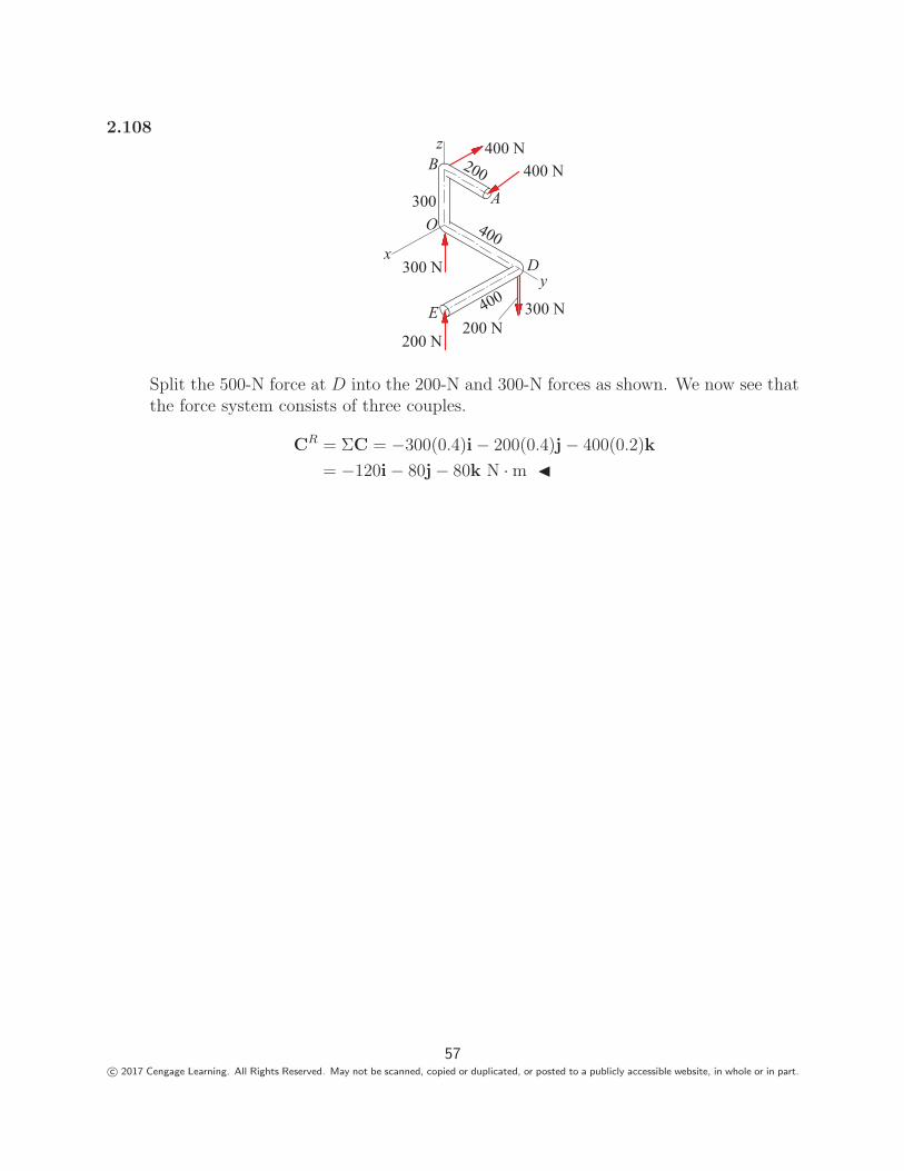
2.108
200
300
400
400
400 N400 N
300 N
200 N
xy
z
OA
B
D
E200 N
300 N
Split the 500-N force at D into the 200-N and 300-N forces as shown. We now see thatthe force system consists of three couples.
CR = ΣC = −300(0.4)i − 200(0.4)j − 400(0.2)k
= −120i − 80j − 80k N · m �
57c© 2017 Cengage Learning. All Rights Reserved. May not be scanned, copied or duplicated, or posted to a publicly accessible website, in whole or in part.

Engineering Mechanics: Statics, Fourth Edition Pytel / Kiusalaas
1
Basic Operations with Force Systems
Chapter 2
Engineering Mechanics: Statics, Fourth Edition Pytel / Kiusalaas
2
• In this chapter we will study the effects of forces on particles and rigid bodies.
• We will learn to use vector algebra to reduce a system of force to a simpler, equivalent system.
• If all forces are concurrent (all forces intersect at the same point), we show the equivalent system is a single force.
• The reduction of a nonconcurrent force system requires two additional vector concepts: the moment of a force and the couple.
Introduction
Engineering Mechanics: Statics, Fourth Edition Pytel / Kiusalaas
3
• All vectors are quantities that have magnitude and direction, and combine according to the parallelogram law for addition.
• Two vectors that have the same magnitude and direction are equal.
• In mechanics, the term equivalence implies interchangeability; two vectors are equivalent if they are interchangeable without a change outcome.
• Equality does not result in equivalence.
Ex. A force applied to a certain body does not have the same effect on the body as an equal force acting at a different point.
Equivalence of Vectors
Engineering Mechanics: Statics, Fourth Edition Pytel / Kiusalaas
4
From the viewpoint of equivalence, vectors representing physical quantities area classified into the following three types:
• Fixed vectors: Equivalent vectors that have the same magnitude, direction, and point of application.
• Sliding vectors: Equivalent vectors that have the same magnitude, direction, and line of action.
• Free vectors: Equivalent vectors that have the same magnitude and direction.
Equivalence of Vectors
Engineering Mechanics: Statics, Fourth Edition Pytel / Kiusalaas
5
• Force is a mechanical interaction between bodies.
• Force can affect both the motion and the deformation of a body on which it acts.
• The area of contact force can be approximated to a point and is said to be concentrated at the point of contact.
• The line of action of a concentrated force is the line that passes through the point of application and is parallel to the force.
Force
Engineering Mechanics: Statics, Fourth Edition Pytel / Kiusalaas
6
• Force is a fixed vector because one of its characteristics is its point of application.
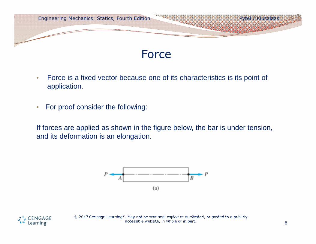
• For proof consider the following:
If forces are applied as shown in the figure below, the bar is under tension, and its deformation is an elongation.
Force
Engineering Mechanics: Statics, Fourth Edition Pytel / Kiusalaas
7
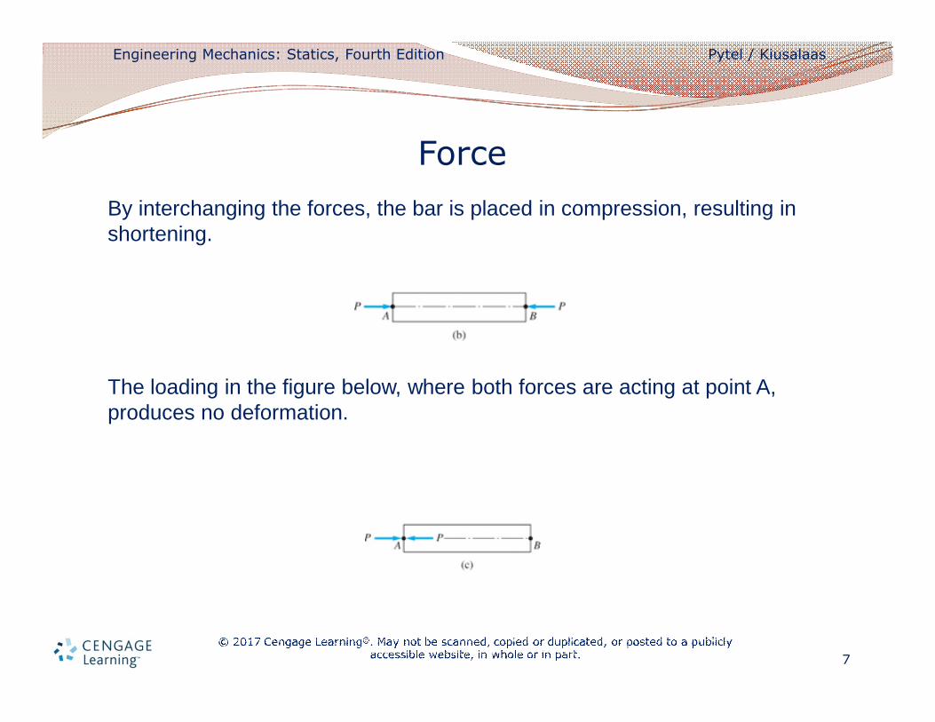
By interchanging the forces, the bar is placed in compression, resulting in shortening.
The loading in the figure below, where both forces are acting at point A, produces no deformation.
Force
Engineering Mechanics: Statics, Fourth Edition Pytel / Kiusalaas
8
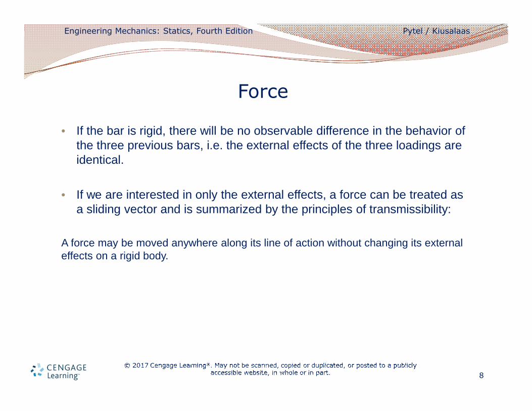
• If the bar is rigid, there will be no observable difference in the behavior of the three previous bars, i.e. the external effects of the three loadings are identical.
• If we are interested in only the external effects, a force can be treated as a sliding vector and is summarized by the principles of transmissibility:
A force may be moved anywhere along its line of action without changing its external effects on a rigid body.
Force
Engineering Mechanics: Statics, Fourth Edition Pytel / Kiusalaas
9
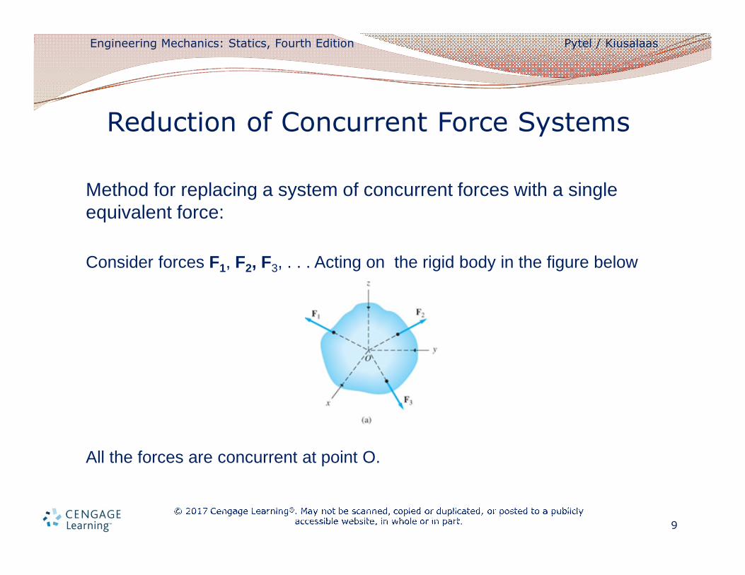
Method for replacing a system of concurrent forces with a single equivalent force:
Consider forces F1, F2, F3, . . . Acting on the rigid body in the figure below
All the forces are concurrent at point O.
Reduction of Concurrent Force Systems
Engineering Mechanics: Statics, Fourth Edition Pytel / Kiusalaas
10
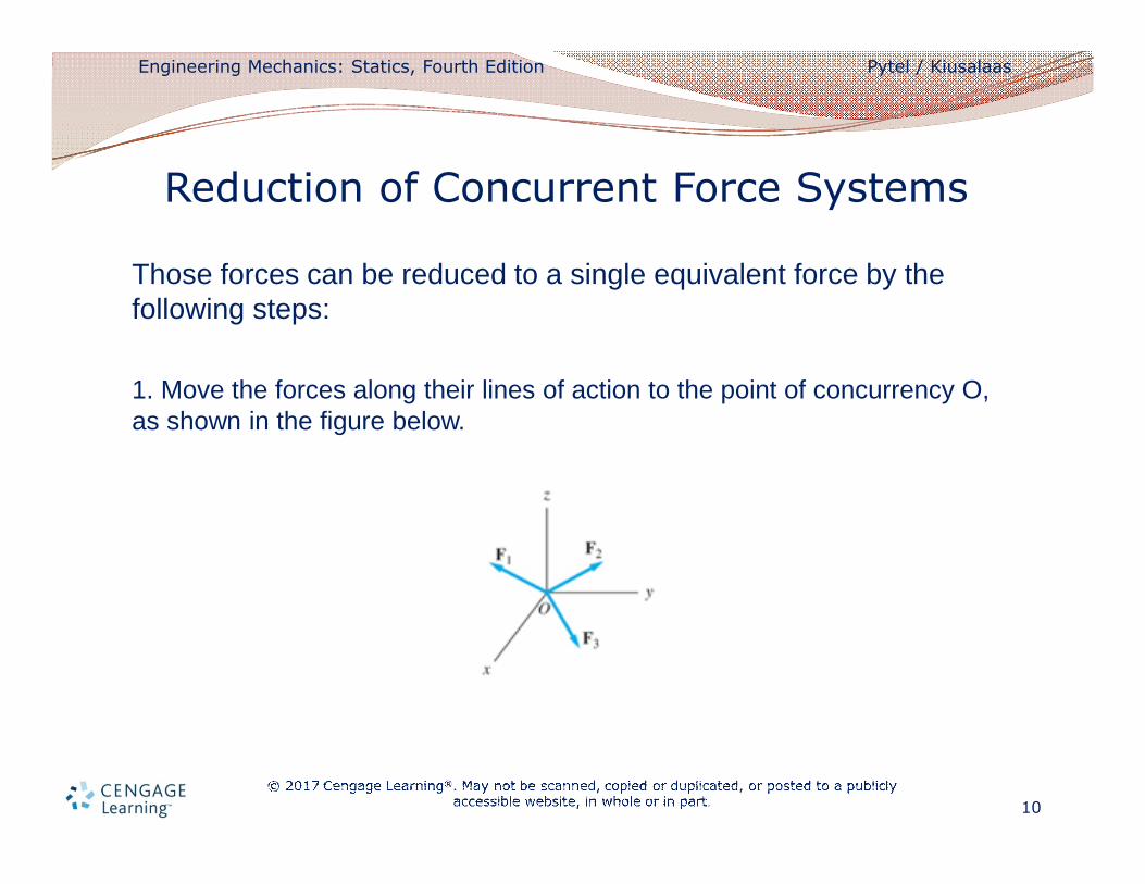
Those forces can be reduced to a single equivalent force by the following steps:
1. Move the forces along their lines of action to the point of concurrency O, as shown in the figure below.
Reduction of Concurrent Force Systems
Engineering Mechanics: Statics, Fourth Edition Pytel / Kiusalaas
11
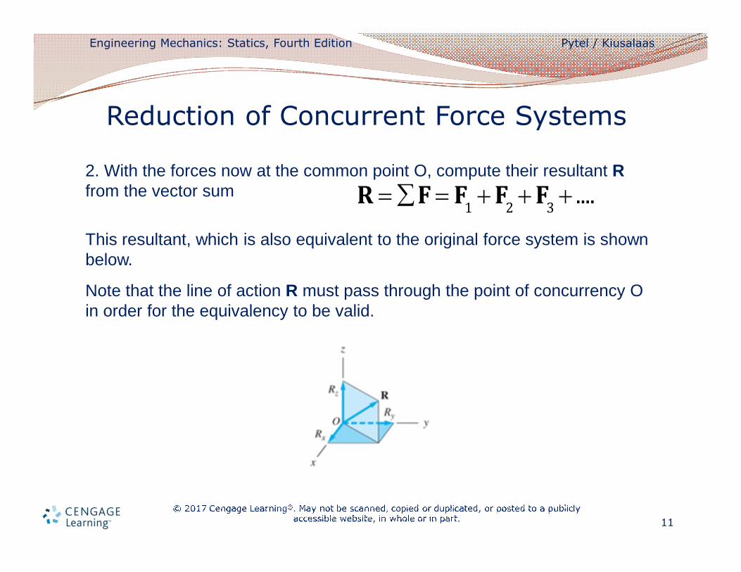
2. With the forces now at the common point O, compute their resultant Rfrom the vector sum
This resultant, which is also equivalent to the original force system is shown below.
Note that the line of action R must pass through the point of concurrency O in order for the equivalency to be valid.
Reduction of Concurrent Force Systems
R = åF = F1
+ F2
+ F3
+ ....
Engineering Mechanics: Statics, Fourth Edition Pytel / Kiusalaas
12
• A body tends to move in the direction of the force, and the magnitude of the force is proportional to its ability to translate the body.
• The tendency of a force to rotate a body is known as the moment of a force about a point.
• The rotational effect depends on the magnitude of the force and the distance between the point and the line of action of the force.
Moment of a Force about a Point
Engineering Mechanics: Statics, Fourth Edition Pytel / Kiusalaas
13
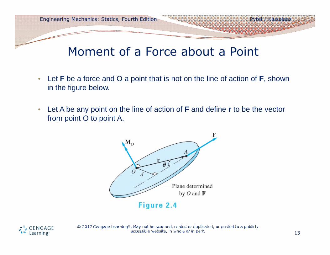
• Let F be a force and O a point that is not on the line of action of F, shown in the figure below.
• Let A be any point on the line of action of F and define r to be the vector from point O to point A.
Moment of a Force about a Point
Engineering Mechanics: Statics, Fourth Edition Pytel / Kiusalaas
14
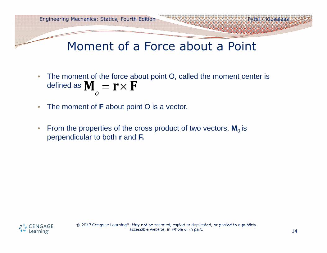
• The moment of the force about point O, called the moment center is defined as
• The moment of F about point O is a vector.
• From the properties of the cross product of two vectors, M0 is perpendicular to both r and F.
Moment of a Force about a Point
Mo
= r ´ F
Engineering Mechanics: Statics, Fourth Edition Pytel / Kiusalaas
15
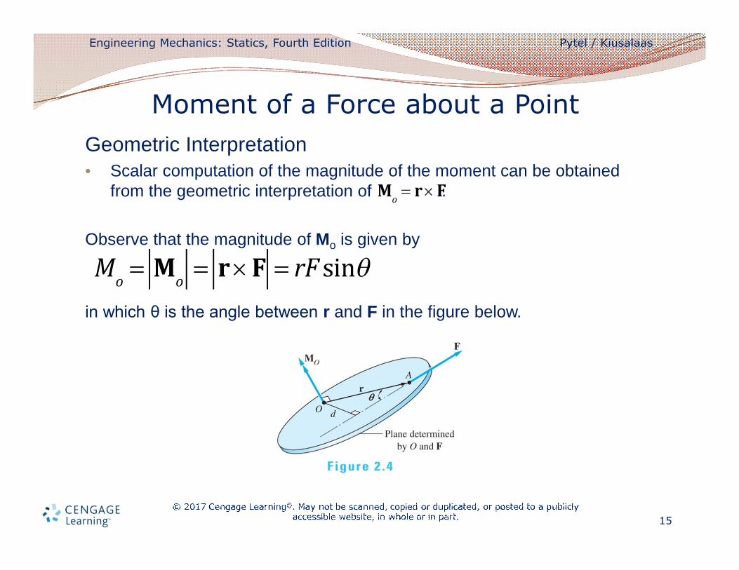
Geometric Interpretation• Scalar computation of the magnitude of the moment can be obtained
from the geometric interpretation of .
Observe that the magnitude of Mo is given by
in which θ is the angle between r and F in the figure below.
Moment of a Force about a Point
Mo
= r ´ F
Mo
= Mo
= r ´ F = rF sinq
Engineering Mechanics: Statics, Fourth Edition Pytel / Kiusalaas
16
• From the previous figure we see that where d is the perpendicular distance from the moment center to the line of action of the force F, called the moment arm of the force.
• The magnitude of Mo is
• Magnitude of Mo depends only on the magnitude of the force and the perpendicular distance d, thus a force may be moved anywhere along its line of action without changing its moment about a point.
• In this application, a force may be treated as a sliding vector.
Moment of a Force about a Point
r sinq = d
Mo
= Fd
Engineering Mechanics: Statics, Fourth Edition Pytel / Kiusalaas
17
Principles of moments
• When determining the moment of a force about a point, it is convenient to use the principle of moments, i.e. the Varignon’s theorem:
The moment of a force about a point is equal to the sum of the components about that point.
Moment of a Force about a Point
Engineering Mechanics: Statics, Fourth Edition Pytel / Kiusalaas
18
Proof of the Varignon’s theorem
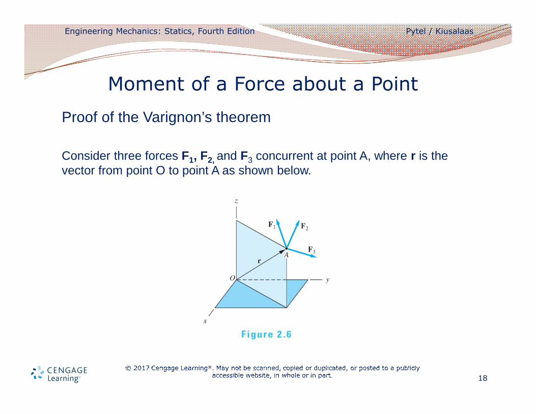
Consider three forces F1, F2, and F3 concurrent at point A, where r is the vector from point O to point A as shown below.
Moment of a Force about a Point
Engineering Mechanics: Statics, Fourth Edition Pytel / Kiusalaas
19
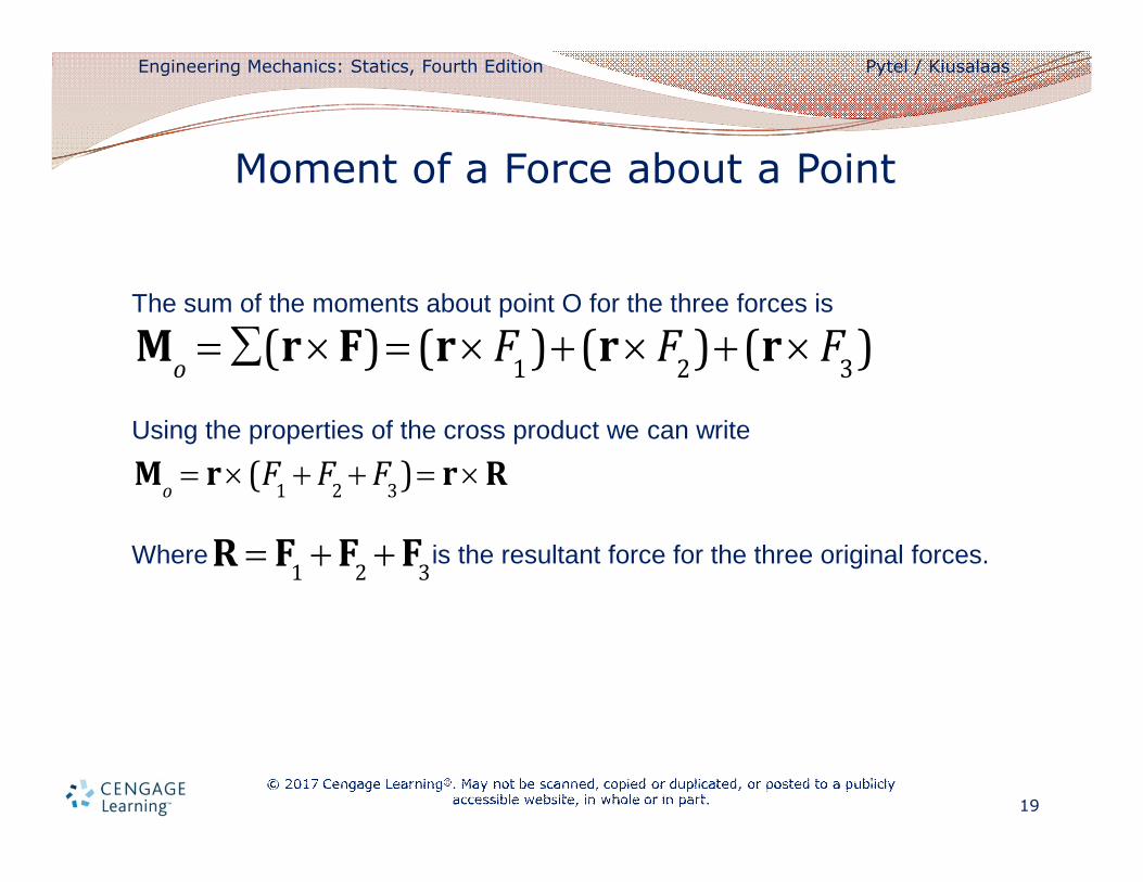
The sum of the moments about point O for the three forces is
Using the properties of the cross product we can write
Where is the resultant force for the three original forces.
Moment of a Force about a Point
Mo
= å(r ´ F) = (r ´ F1)+(r ´ F
2)+(r ´ F
3)
Mo
= r ´(F1
+ F2
+ F3)= r ´ R
R = F1
+ F2
+ F3
Engineering Mechanics: Statics, Fourth Edition Pytel / Kiusalaas
20
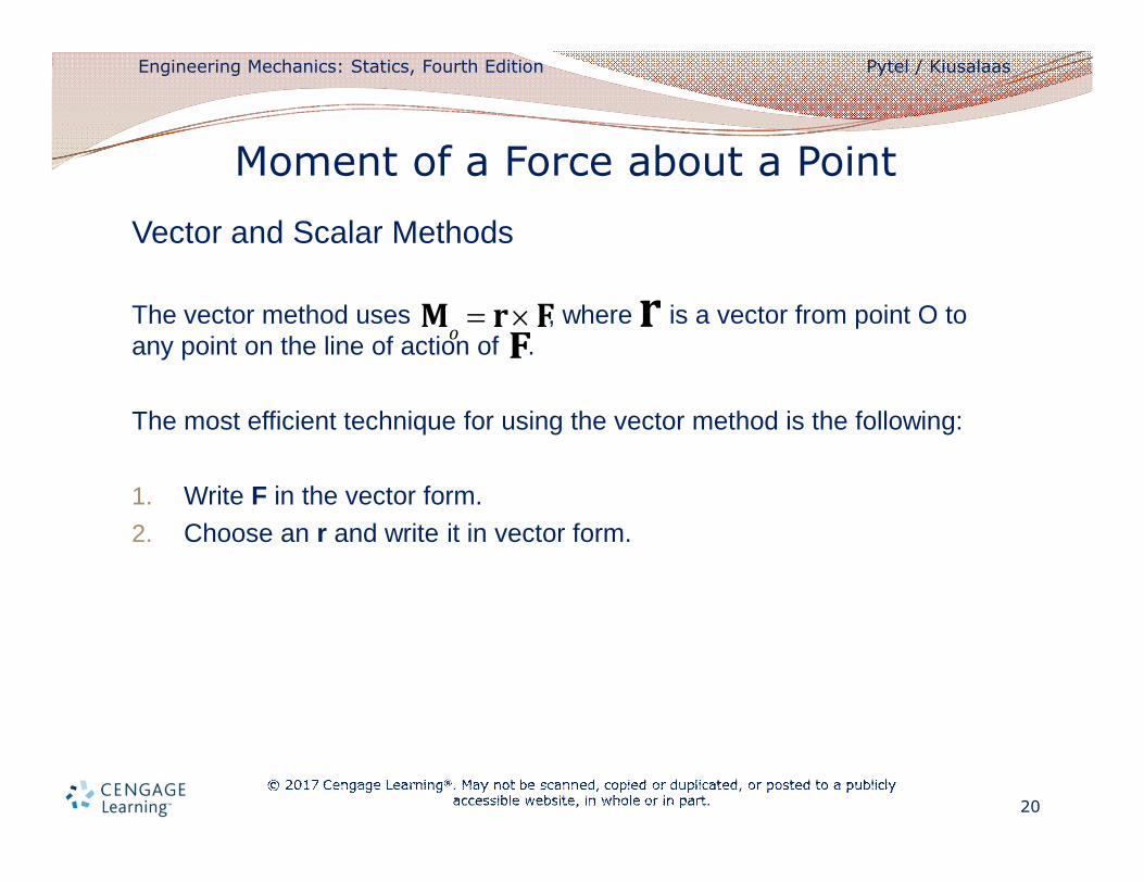
Vector and Scalar Methods
The vector method uses , where is a vector from point O to any point on the line of action of .
The most efficient technique for using the vector method is the following:
1. Write F in the vector form.
2. Choose an r and write it in vector form.
Moment of a Force about a Point
Mo
= r ´ F rF
Engineering Mechanics: Statics, Fourth Edition Pytel / Kiusalaas
21
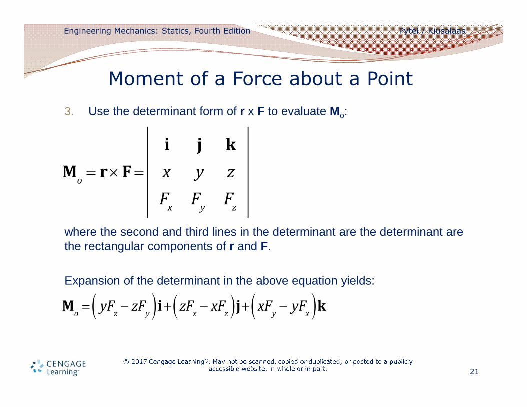
3. Use the determinant form of r x F to evaluate Mo:
where the second and third lines in the determinant are the determinant are the rectangular components of r and F.
Expansion of the determinant in the above equation yields:
Moment of a Force about a Point
Mo
= r ´ F =
i j k
x y z
Fx
Fy
Fz
Mo
= yFz
- zFy( )i+ zF
x- xF
z( )j+ xFy
- yFx( )k
Engineering Mechanics: Statics, Fourth Edition Pytel / Kiusalaas
22
• In the scalar method, the magnitude of the moment of the force F about the point O is found form Mo = Fd, with d as the moment arm of the force.
• For this method, the sense of the moment must be determined by inspection.
• The scalar method is convenient only when the moment arm d can be easily determined.
Moment of a Force about a Point
Engineering Mechanics: Statics, Fourth Edition Pytel / Kiusalaas
23
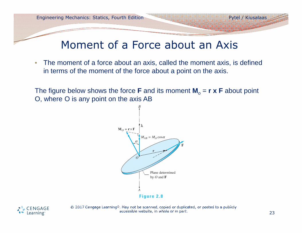
• The moment of a force about an axis, called the moment axis, is defined in terms of the moment of the force about a point on the axis.
The figure below shows the force F and its moment Mo = r x F about point O, where O is any point on the axis AB
Moment of a Force about an Axis
Engineering Mechanics: Statics, Fourth Edition Pytel / Kiusalaas
24
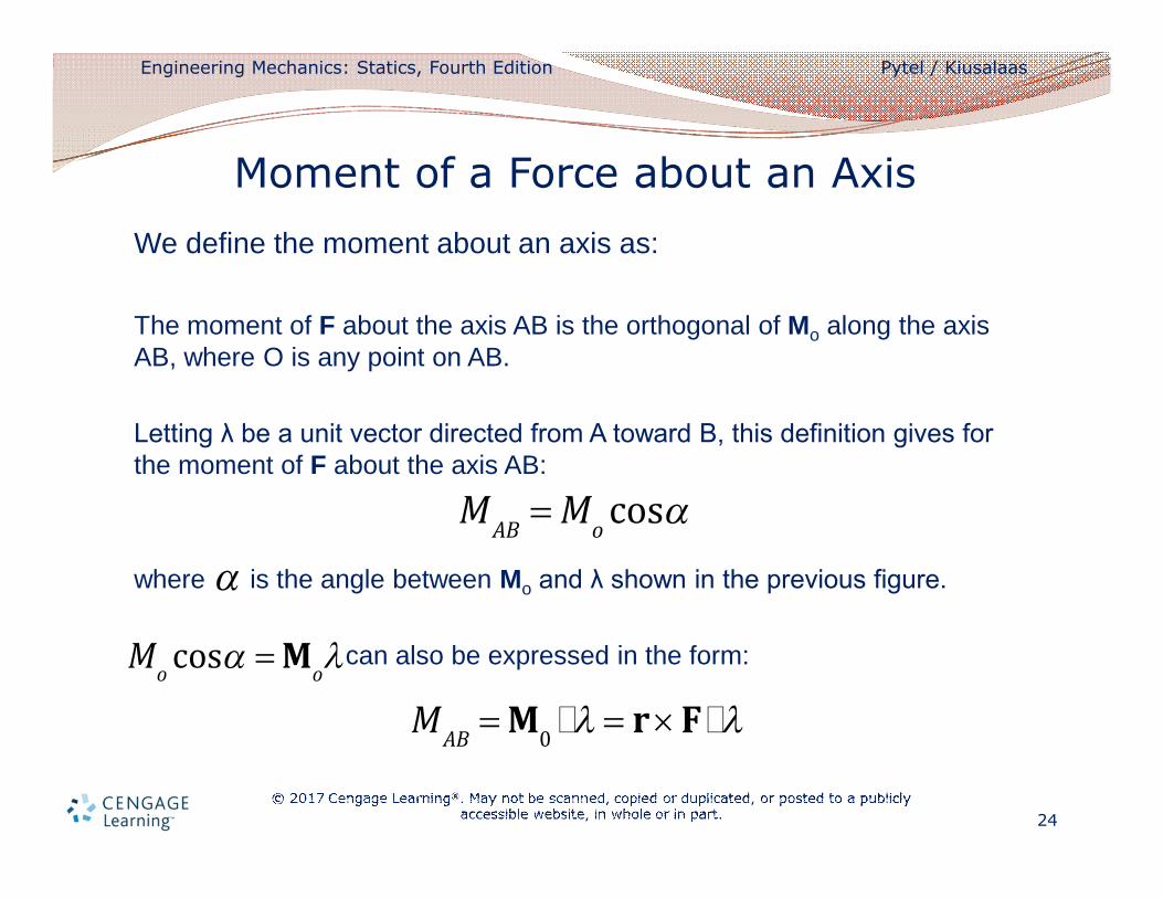
We define the moment about an axis as:
The moment of F about the axis AB is the orthogonal of Mo along the axis AB, where O is any point on AB.
Letting λ be a unit vector directed from A toward B, this definition gives for the moment of F about the axis AB:
where is the angle between Mo and λ shown in the previous figure.
can also be expressed in the form:
Moment of a Force about an Axis
MAB
= Mocosa
a
Mocosa = M
ol
MAB
= M0il = r ´ Fil
Engineering Mechanics: Statics, Fourth Edition Pytel / Kiusalaas
25
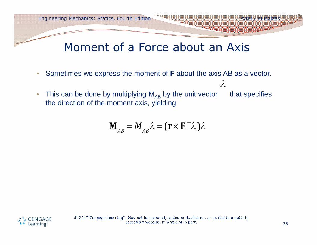
• Sometimes we express the moment of F about the axis AB as a vector.
• This can be done by multiplying MAB by the unit vector that specifies the direction of the moment axis, yielding
Moment of a Force about an Axis
l
MAB
= MAB
l = (r ´ Fil)l
Engineering Mechanics: Statics, Fourth Edition Pytel / Kiusalaas
26
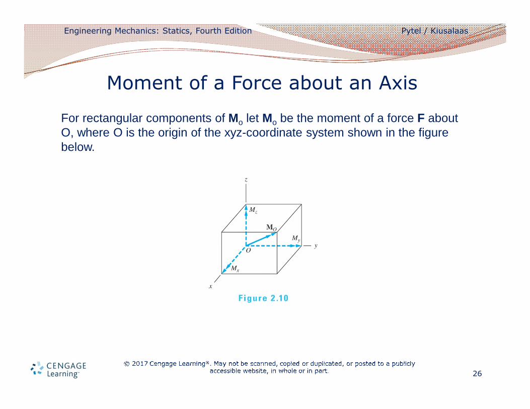
For rectangular components of Mo let Mo be the moment of a force F about O, where O is the origin of the xyz-coordinate system shown in the figure below.
Moment of a Force about an Axis
Engineering Mechanics: Statics, Fourth Edition Pytel / Kiusalaas
27
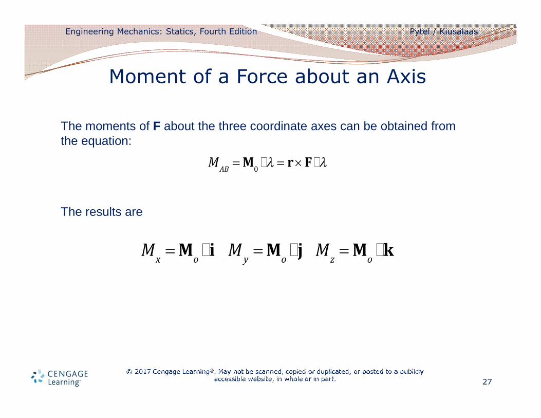
The moments of F about the three coordinate axes can be obtained from the equation:
The results are
Moment of a Force about an Axis
MAB
= M0il = r ´ Fil
Mx
= Moii M
y= M
oij M
z= M
oik
Engineering Mechanics: Statics, Fourth Edition Pytel / Kiusalaas
28
We can now draw the conclusion:
• The rectangular components of the moment of a force about the origin O are equal to the moments of the force about the coordinate axis.
i.e.
• Mx, My, and Mz shown in the previous figure are equal to the moments of the force about the coordinate axes.
Moment of a Force about an Axis
Mo
= Mxi + M
yj+ M
zk
Engineering Mechanics: Statics, Fourth Edition Pytel / Kiusalaas
29
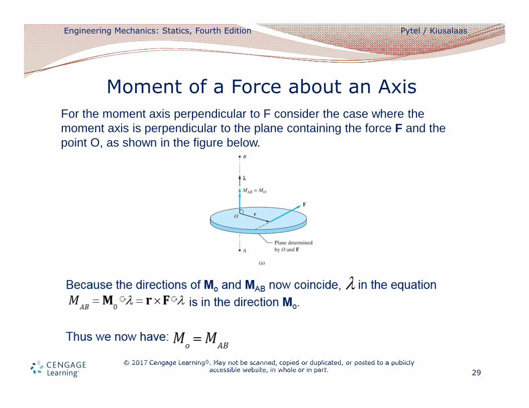
For the moment axis perpendicular to F consider the case where the moment axis is perpendicular to the plane containing the force F and the point O, as shown in the figure below.
Moment of a Force about an Axis

Engineering Mechanics: Statics, Fourth Edition Pytel / Kiusalaas
30
Geometric Interpretation
Examine the geometric interpretation of the equation
Suppose we are given in the arbitrary force F and an arbitrary axis AB, as shown in the figure below.
Moment of a Force about an Axis
MAB
= r ´ Fil
Engineering Mechanics: Statics, Fourth Edition Pytel / Kiusalaas
31
We construct a plane P that is perpendicular to the AB axis and let O and C be the points where the axis and the line of action of the force intersects P.
The vector from O to C is denoted by r, and is the unit vector along the axis AB.
We then resolve F into two components: F1 and F2, which are parallel and perpendicular to the axis AB.
Moment of a Force about an Axis
l
Engineering Mechanics: Statics, Fourth Edition Pytel / Kiusalaas
32
In terms of these components, the moment of F about the axis AB is
Because is perpendicular to , , and we get:
Moment of a Force about an Axis
MAB
= r ´ Fil = r ´(F1
+ F2)il
= r ´ F1il + r ´ F
2il
r ´ F1
r ´ F1il = 0l
MAB
= r ´ F2il
Engineering Mechanics: Statics, Fourth Edition Pytel / Kiusalaas
33
Substitution of where d is the perpendicular distance from O to the line of action of F2, yields:
We see that the moment of F about the axis AB equals the product of the component of F that is perpendicular to AB and the perpendicular distance of this component from AB.
Moment of a Force about an Axis
r ´ F2il = F
2d
MAB
= F2d
Engineering Mechanics: Statics, Fourth Edition Pytel / Kiusalaas
34
The moment of a force about an axis possesses the following physical characteristics:
• A force that is parallel to the moment axis has no moment about that axis.
• If the line of action of a force intersects the moment axis, the force has no moment about that axis.
• The moment of a force is proportional to its component that is perpendicular to the moment axis, and the moment arm of that component.
• The sense of the moment is consistent with the direction in which the force would tend to rotate a body.
Moment of a Force about an Axis
Engineering Mechanics: Statics, Fourth Edition Pytel / Kiusalaas
35
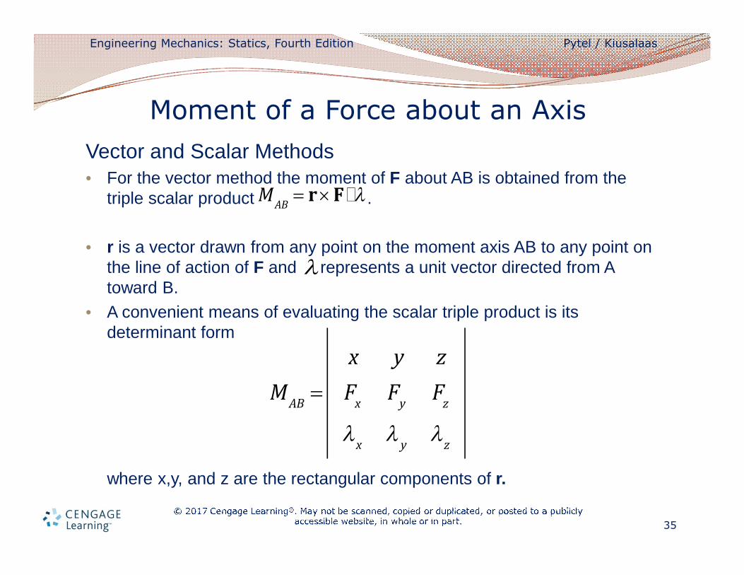
Vector and Scalar Methods• For the vector method the moment of F about AB is obtained from the
triple scalar product .
• r is a vector drawn from any point on the moment axis AB to any point on the line of action of F and represents a unit vector directed from A toward B.
• A convenient means of evaluating the scalar triple product is its determinant form
where x,y, and z are the rectangular components of r.
Moment of a Force about an Axis
MAB
= r ´ Fil
l
MAB
=
x y z
Fx
Fy
Fz
lx
ly
lz
Engineering Mechanics: Statics, Fourth Edition Pytel / Kiusalaas
36
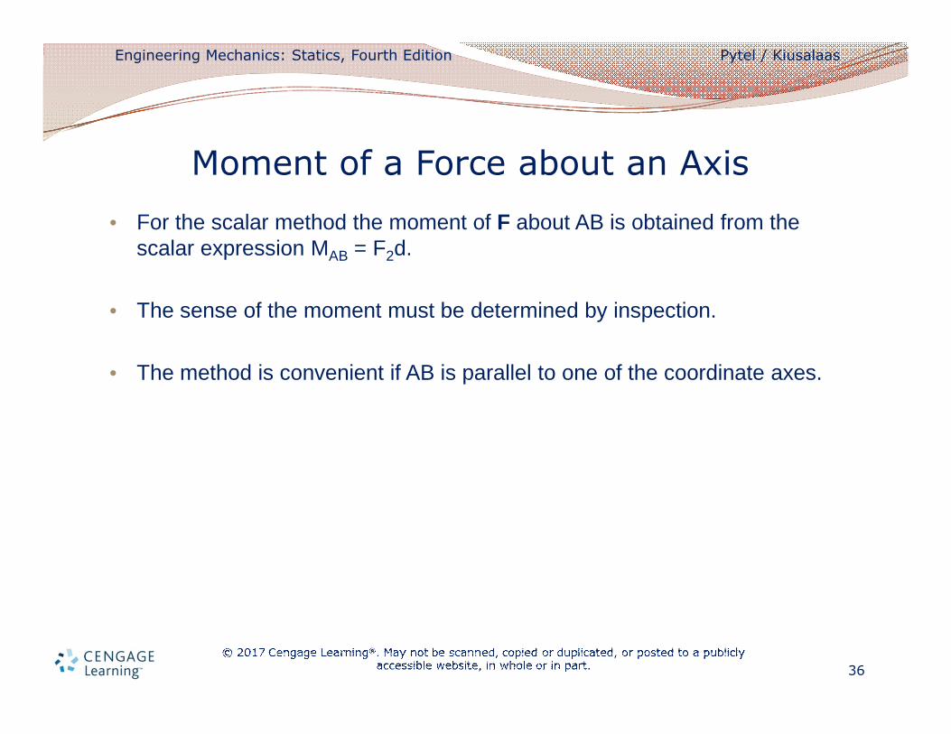
• For the scalar method the moment of F about AB is obtained from the scalar expression MAB = F2d.
• The sense of the moment must be determined by inspection.
• The method is convenient if AB is parallel to one of the coordinate axes.
Moment of a Force about an Axis
Engineering Mechanics: Statics, Fourth Edition Pytel / Kiusalaas
37
• A force has two effects on a rigid body: translation due to the force itself and rotation due to the moment of the force.
• A couple is a purely rotational effect; it has a moment but no resultant force.
• Couples play an important role in the analysis of a force system.
Couples
Engineering Mechanics: Statics, Fourth Edition Pytel / Kiusalaas
38
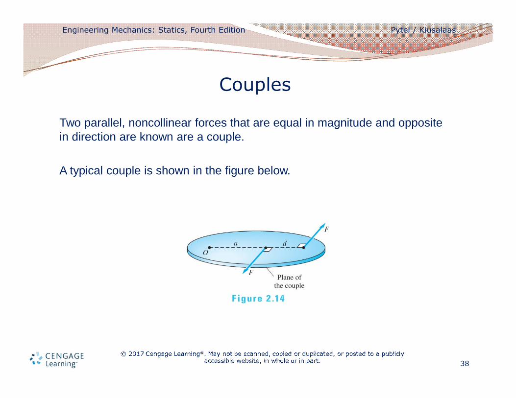
Two parallel, noncollinear forces that are equal in magnitude and opposite in direction are known are a couple.
A typical couple is shown in the figure below.
Couples
Engineering Mechanics: Statics, Fourth Edition Pytel / Kiusalaas
39
• The two forces of equal magnitude F are oppositely directed along the lines of action that are separated by the perpendicular distance d.
• The lines of action of the two forces determine a plane that we call the plane of the couple.
• The two forces that form a couple have some interesting properties, which will become apparent when we calculate their combined moment about a point.
Couples
Engineering Mechanics: Statics, Fourth Edition Pytel / Kiusalaas
40
Moment of a Couple about a Point
• The moment of a couple about a point is the sum of the moments of the two forces that form the couple.
• When calculating the moment of a couple about a point, either the scalar method or the vector method may be used.
Couples
Engineering Mechanics: Statics, Fourth Edition Pytel / Kiusalaas
41
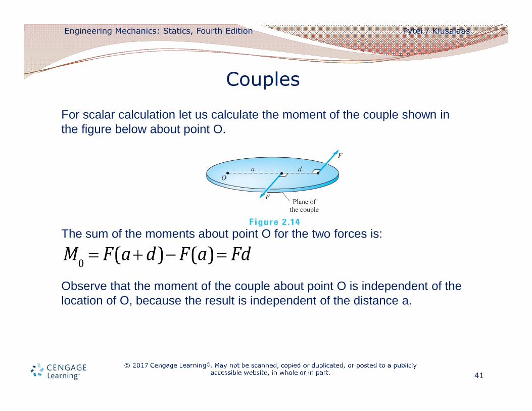
For scalar calculation let us calculate the moment of the couple shown in the figure below about point O.
The sum of the moments about point O for the two forces is:
Observe that the moment of the couple about point O is independent of the location of O, because the result is independent of the distance a.
Couples
M0
= F(a+ d)- F(a) = Fd
Engineering Mechanics: Statics, Fourth Edition Pytel / Kiusalaas
42
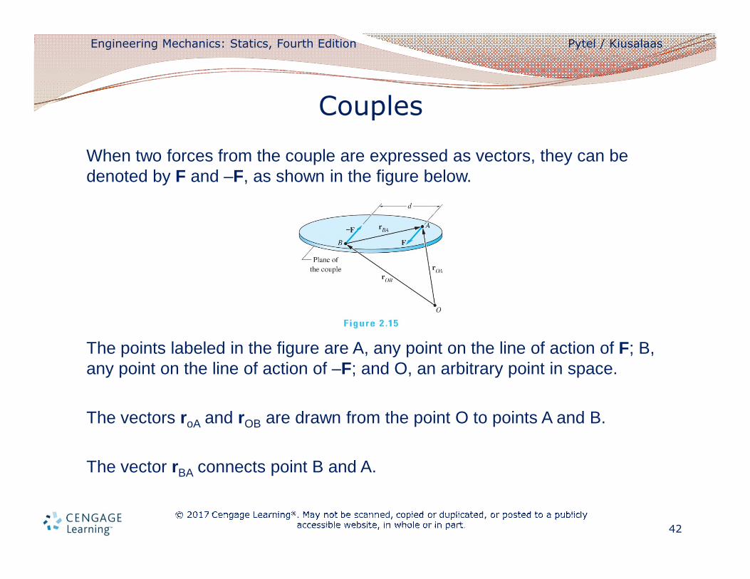
When two forces from the couple are expressed as vectors, they can be denoted by F and –F, as shown in the figure below.
The points labeled in the figure are A, any point on the line of action of F; B, any point on the line of action of –F; and O, an arbitrary point in space.
The vectors roA and rOB are drawn from the point O to points A and B.
The vector rBA connects point B and A.
Couples
Engineering Mechanics: Statics, Fourth Edition Pytel / Kiusalaas
43
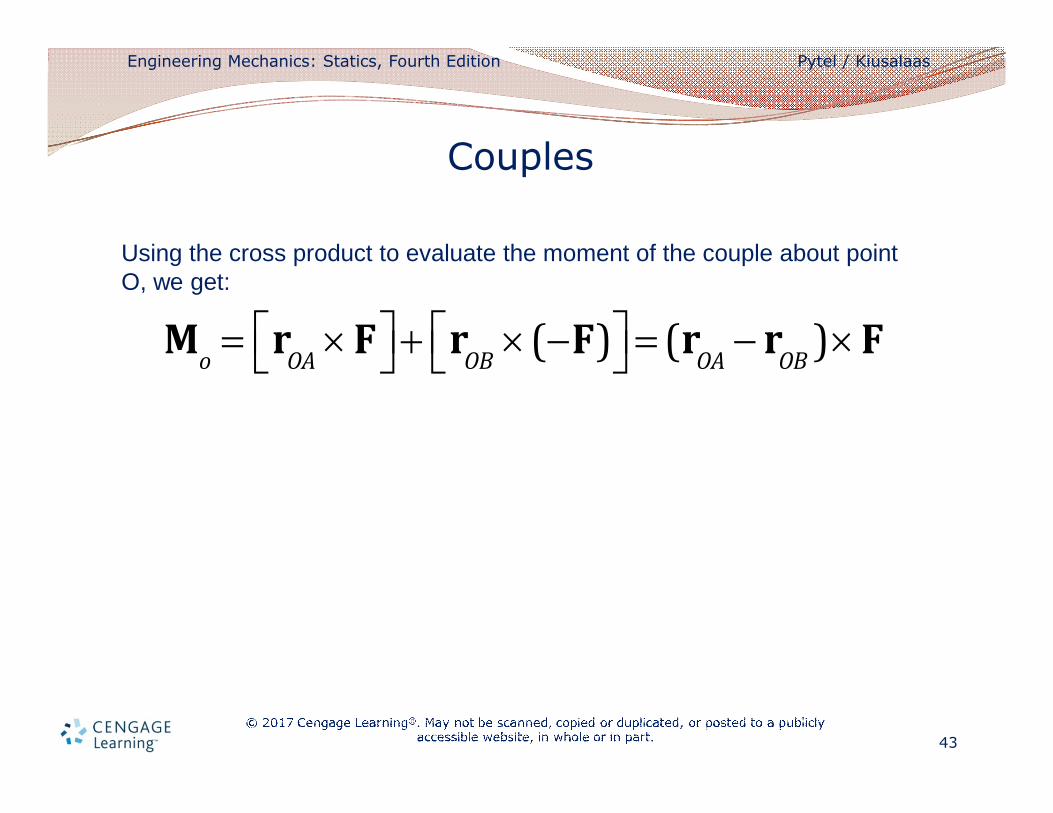
Using the cross product to evaluate the moment of the couple about point O, we get:
Couples
Mo
= rOA
´ Féë ùû + rOB
´(-F)éë ùû = (rOA
- rOB
)´ F
Engineering Mechanics: Statics, Fourth Edition Pytel / Kiusalaas
44
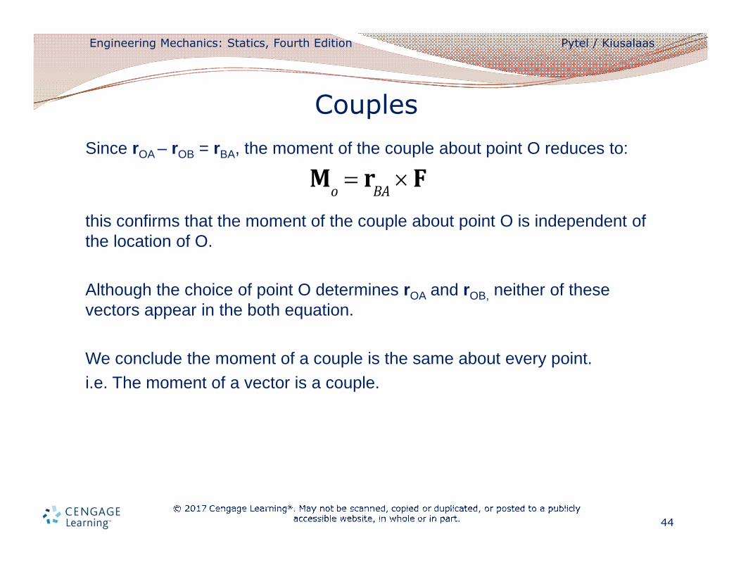
Since rOA – rOB = rBA, the moment of the couple about point O reduces to:
this confirms that the moment of the couple about point O is independent of the location of O.
Although the choice of point O determines rOA and rOB, neither of these vectors appear in the both equation.
We conclude the moment of a couple is the same about every point.
i.e. The moment of a vector is a couple.
Couples
Mo
= rBA
´ F
Engineering Mechanics: Statics, Fourth Edition Pytel / Kiusalaas
45
Equivalent couples
• Because a couple has no resultant force, its only effect on a rigid body is its moment.
• Because of this, two couples that have the same moment are equivalent.
Couples
Engineering Mechanics: Statics, Fourth Edition Pytel / Kiusalaas
46
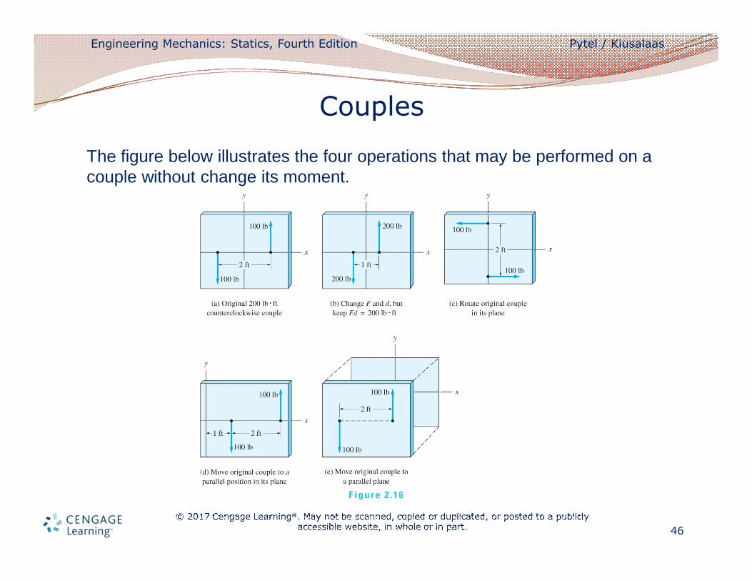
The figure below illustrates the four operations that may be performed on a couple without change its moment.
Couples
Engineering Mechanics: Statics, Fourth Edition Pytel / Kiusalaas
47
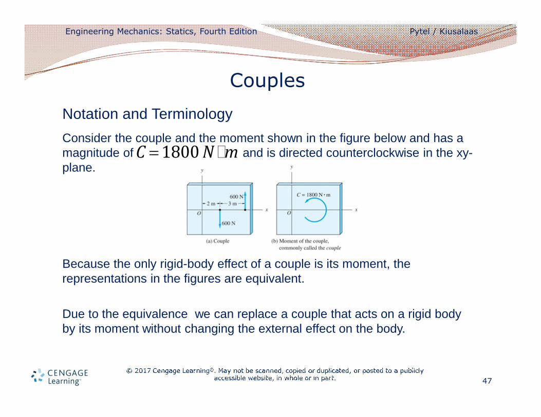
Notation and Terminology
Consider the couple and the moment shown in the figure below and has a magnitude of and is directed counterclockwise in the xy-plane.
Because the only rigid-body effect of a couple is its moment, the representations in the figures are equivalent.
Due to the equivalence we can replace a couple that acts on a rigid body by its moment without changing the external effect on the body.
Couples
C = 1800 N im
Engineering Mechanics: Statics, Fourth Edition Pytel / Kiusalaas
48
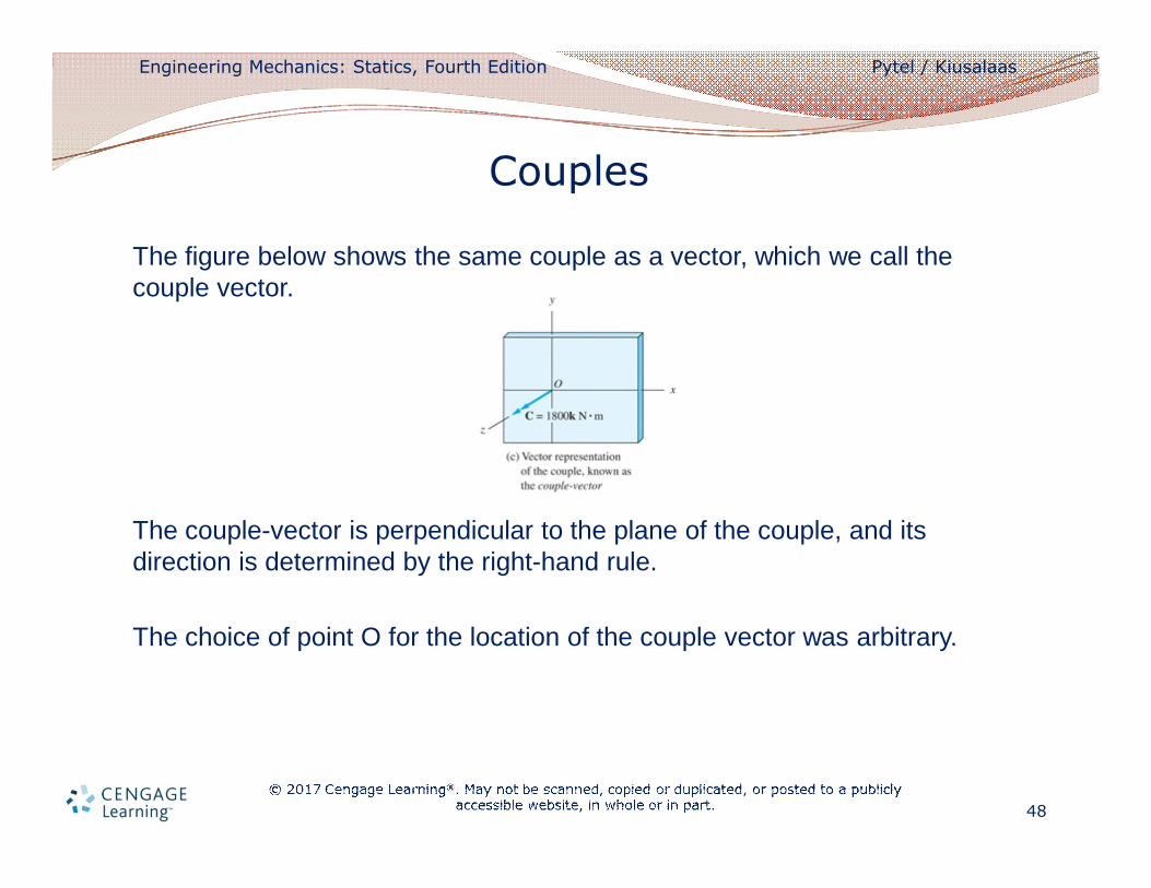
The figure below shows the same couple as a vector, which we call the couple vector.
The couple-vector is perpendicular to the plane of the couple, and its direction is determined by the right-hand rule.
The choice of point O for the location of the couple vector was arbitrary.
Couples
Engineering Mechanics: Statics, Fourth Edition Pytel / Kiusalaas
49
The Addition and Resolution of Couples
• Because couples are vectors, they may be added by the usual rules of vector addition.
• Being free vectors, the requirement that the couples to be added must have a common point of application does not apply.
• Moments of forces can be added only if the moments are taken about the same point.
Couples
Engineering Mechanics: Statics, Fourth Edition Pytel / Kiusalaas
50
• The resolution of couples is no different than the resolution of moments of force.
• For example, the moment of a couple C about an axis AB can be computed as
where is the unit vector in the direction of the axis.
• As with moments of forces, MAB is equal to the rectangular component of C in the direction of AB, and is a measure of the tendency of C to rotate a body about the axis AB.
Couples
MAB
= Cil
l
Engineering Mechanics: Statics, Fourth Edition Pytel / Kiusalaas
51
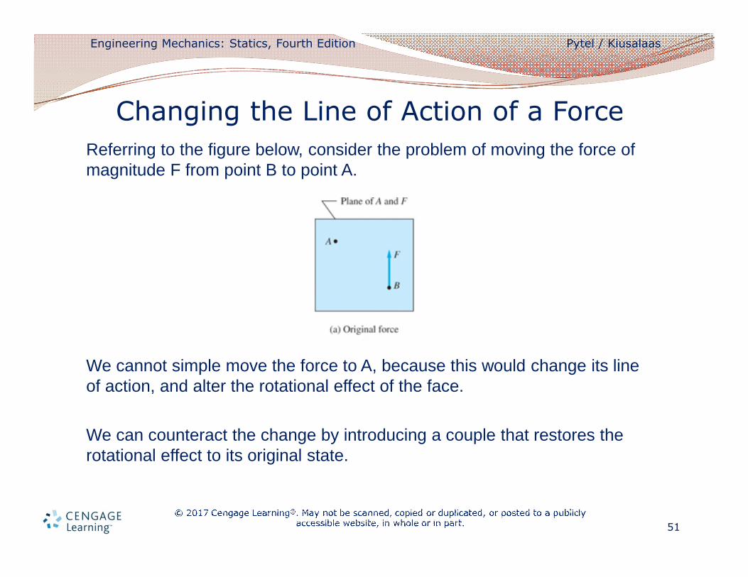
Referring to the figure below, consider the problem of moving the force of magnitude F from point B to point A.
We cannot simple move the force to A, because this would change its line of action, and alter the rotational effect of the face.
We can counteract the change by introducing a couple that restores the rotational effect to its original state.
Changing the Line of Action of a Force
Engineering Mechanics: Statics, Fourth Edition Pytel / Kiusalaas
52
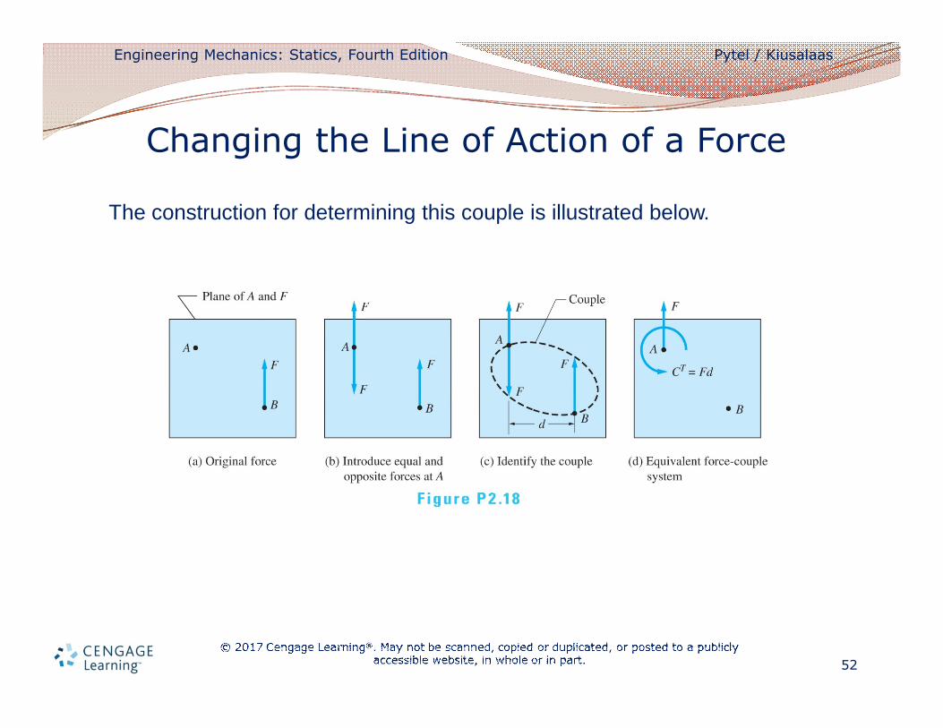
The construction for determining this couple is illustrated below.
Changing the Line of Action of a Force
Engineering Mechanics: Statics, Fourth Edition Pytel / Kiusalaas
53
Our work consists of the following two steps:
1. Introduce two equal and opposite forces of magnitude F at point A, as shown in figure b.
• These forces are parallel to the original force at B.
• Because the forces at A have no net external effect on a rigid
body, the force systems in figure a and b are equivalent.
2. Identify the two forces that form a couple, as has been done in figure c.
• The magnitude of this couple CT = Fd, where d is the distance between the line of action of the forces at A and B.
• The third force and CT thus constitute the force-couple system shown in figure d, which is equivalent to the original force shown in figure a.
Changing the Line of Action of a Force
Engineering Mechanics: Statics, Fourth Edition Pytel / Kiusalaas
54
• We refer to the couple CT as the couple of transfer because it is the couple that must be introduced when a force is transferred from one line of action to another.
• From the previous figure we can conclude: The couple of transfer is equal to the moment of the original (acting at B) about the transfer point A.
Changing the Line of Action of a Force
Engineering Mechanics: Statics, Fourth Edition Pytel / Kiusalaas
55
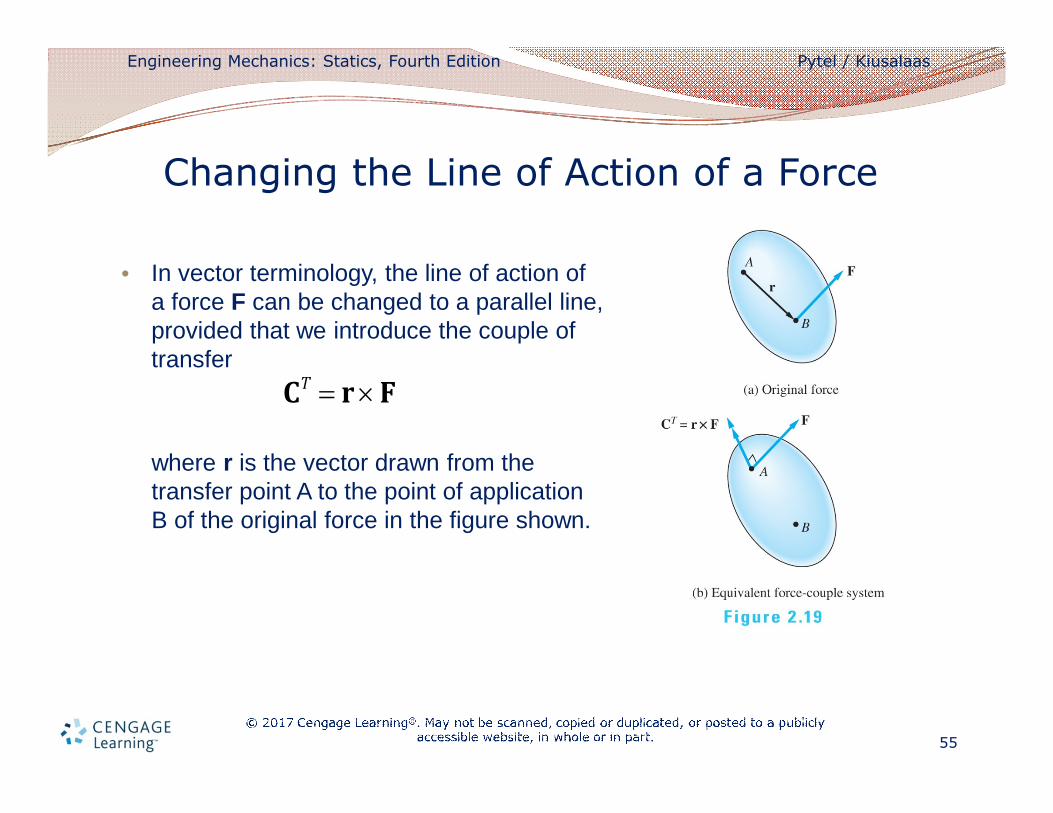
• In vector terminology, the line of action of a force F can be changed to a parallel line, provided that we introduce the couple of transfer
where r is the vector drawn from the transfer point A to the point of application B of the original force in the figure shown.
Changing the Line of Action of a Force
CT = r ´ F
Engineering Mechanics: Statics, Fourth Edition Pytel / Kiusalaas
56
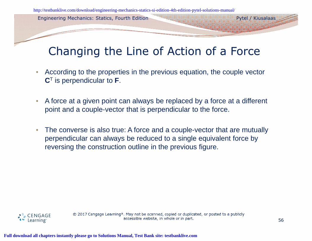
• According to the properties in the previous equation, the couple vector CT is perpendicular to F.
• A force at a given point can always be replaced by a force at a different point and a couple-vector that is perpendicular to the force.
• The converse is also true: A force and a couple-vector that are mutually perpendicular can always be reduced to a single equivalent force by reversing the construction outline in the previous figure.
Changing the Line of Action of a Force
Engineering Mechanics Statics SI Edition 4th Edition Pytel Solutions ManualFull Download: http://testbanklive.com/download/engineering-mechanics-statics-si-edition-4th-edition-pytel-solutions-manual/
Full download all chapters instantly please go to Solutions Manual, Test Bank site: testbanklive.com