Chapter 13 Evaluation of the dynamic bearing capacity of a ... · Evaluation of the dynamic bearing...
20
Chapter 13 Evaluation of the dynamic bearing capacity of a masonry building by means of a characteristics line method M. Maugeri & D. Novità Department of Civil and Environmental Engineering, University of Catania Abstract Strengthening works performed only in the superstructure are often insufficient to prevent damage in buildings in consequence of seismic events. They can avoid the complete collapse of the structure but they cannot ensure the total safety and serviceability of the whole building, often significantly damaged due to its foundation movements (Maugeri et al. [1]; Maugeri & Novità [2]). The goal of the present work is to analyse the dynamic behaviour of the shallow foundation of a full-scale masonry building in terms of bearing capacity, on the basis of the dynamic characterization of the subsoil and of the local site response. As suggested by Eurocode 8 (EC8 [3]), the design vertical resistance was evaluated taking into account the possible effects of the soil inertia forces by means of a new numerical model, developed at the University of Catania, based on the characteristics line method of the theory of the limiting equilibrium (Maugeri & Novità [2]). The seismic bearing capacity analysis was also performed according to the limit analysis method proposed by Richard et al. [4], and to the kinematic approach of the yield design theory mechanism proposed by Paolucci & Pecker [5]. The results were compared with those provided by the worldwide used Brinch-Hansen method [6], which ignore the presence of inertial forces in the soil. SEISMIC PREVENTION OF DAMAGE 243 www.witpress.com, ISSN 1755-8336 (on-line) WIT Transactions on State of the Art in Science and Engineering, Vol 8, © 2005 WIT Press doi:10.2495/1-84564-004-7/13
Transcript of Chapter 13 Evaluation of the dynamic bearing capacity of a ... · Evaluation of the dynamic bearing...
Chapter 13
Evaluation of the dynamic bearing capacity of a masonry building by means of a characteristics line method
M. Maugeri & D. Novità Department of Civil and Environmental Engineering, University of Catania
Abstract
Strengthening works performed only in the superstructure are often insufficient to prevent damage in buildings in consequence of seismic events. They can avoid the complete collapse of the structure but they cannot ensure the total safety and serviceability of the whole building, often significantly damaged due to its foundation movements (Maugeri et al. [1]; Maugeri & Novità [2]). The goal of the present work is to analyse the dynamic behaviour of the shallow foundation of a full-scale masonry building in terms of bearing capacity, on the basis of the dynamic characterization of the subsoil and of the local site response. As suggested by Eurocode 8 (EC8 [3]), the design vertical resistance was evaluated taking into account the possible effects of the soil inertia forces by means of a new numerical model, developed at the University of Catania, based on the characteristics line method of the theory of the limiting equilibrium (Maugeri & Novità [2]). The seismic bearing capacity analysis was also performed according to the limit analysis method proposed by Richard et al. [4], and to the kinematic approach of the yield design theory mechanism proposed by Paolucci & Pecker [5]. The results were compared with those provided by the worldwide used Brinch-Hansen method [6], which ignore the presence of inertial forces in the soil.
SEISMIC PREVENTION OF DAMAGE 243
www.witpress.com, ISSN 1755-8336 (on-line) WIT Transactions on State of the Art in Science and Engineering, Vol 8, © 2005 WIT Press
doi:10.2495/1-84564-004-7/13
1 Introduction
There is a world-wide demand, on understanding the real behaviour of buildings during earthquakes, to take action for prevention of seismic damage in many parts of the world. For example in the case of the urban area of Catania where about 20,000 people were killed out of a population of about 40,000 people during the 1693 earthquake, this disaster may be repeated again in the near future. Although the earthquake sequences that took place in the east part of Sicily on 10 December 1990 were not so destructive for the urban area of Catania, and after the seismic event remedial works were performed on many damaged masonry buildings, it must be underlined that such works do not preserve the masonry elements from structural damage, often caused by subsoil settlements. Remedial works are frequently carried out only in the superstructure, paying no attention to the foundation, and totally neglecting the fact that a structural improvement can be dangerous to the stability of the whole building and can mean only a waste of money if the foundation soundness is not taken into account. The topic of the present paper is to analyse the seismic behaviour of the shallow foundation of a masonry building, focusing on its bearing capacity according to a new approach based on the characteristics line method (Carfì [7]; Maugeri & Novità [2]). This allows one to evaluate the seismic bearing capacity considering the effect of the inertia forces of the structure as well as the possible effects of the inertia forces in the supporting soil itself, as suggested by Eurocode 8 (EC8 [3]). In fact, EC8 [3] prescribes calculating the design vertical bearing capacity by considering the load inclination and eccentricity arising from the inertia forces of the structure, as well as the possible effects of the soil inertia forces. But while it suggests calculating the load inclination and eccentricity as reported in annex B of Eurocode 7 (EC7 [8]), it does not give any suggestions regarding the way of taking into account the soil inertia. The procedure proposed represents a simple and useful tool for the evaluation of the dynamic bearing capacity of shallow foundations, considering both the over-structure inertia as well as the soil inertia. In this paper, firstly the foundation behaviour was analysed considering the inelastic spectrum suggested by the Italian Rules (D.M.19/01/1996 [9]) and characterized by a specific peak ground acceleration, according to the indication for the second seismic category where the city of Catania is located. Secondly, a local site response was carried out and the seismic bearing capacity of the foundation was evaluated taking into account the average value of the inelastic spectral-pseudo acceleration of the inelastic response spectrum for the building site.
2 The building, the site characterization and its response 2.1 The building analysed To have an overview of the actual scenario of the urban area of Catania, in terms of the historical and structural state of degradation of the buildings,
244 SEISMIC PREVENTION OF DAMAGE
www.witpress.com, ISSN 1755-8336 (on-line) WIT Transactions on State of the Art in Science and Engineering, Vol 8, © 2005 WIT Press
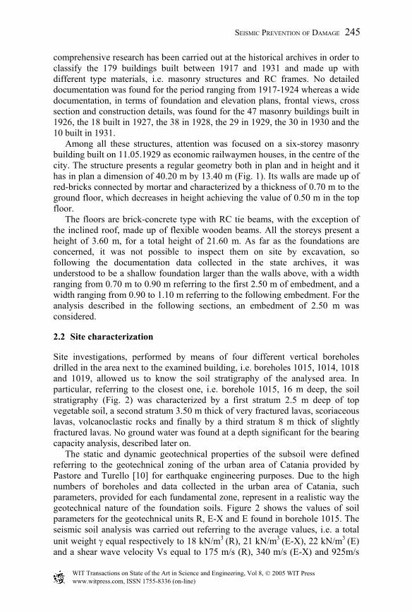
comprehensive research has been carried out at the historical archives in order to classify the 179 buildings built between 1917 and 1931 and made up with different type materials, i.e. masonry structures and RC frames. No detailed documentation was found for the period ranging from 1917-1924 whereas a wide documentation, in terms of foundation and elevation plans, frontal views, cross section and construction details, was found for the 47 masonry buildings built in 1926, the 18 built in 1927, the 38 in 1928, the 29 in 1929, the 30 in 1930 and the 10 built in 1931. Among all these structures, attention was focused on a six-storey masonry building built on 11.05.1929 as economic railwaymen houses, in the centre of the city. The structure presents a regular geometry both in plan and in height and it has in plan a dimension of 40.20 m by 13.40 m (Fig. 1). Its walls are made up of red-bricks connected by mortar and characterized by a thickness of 0.70 m to the ground floor, which decreases in height achieving the value of 0.50 m in the top floor. The floors are brick-concrete type with RC tie beams, with the exception of the inclined roof, made up of flexible wooden beams. All the storeys present a height of 3.60 m, for a total height of 21.60 m. As far as the foundations are concerned, it was not possible to inspect them on site by excavation, so following the documentation data collected in the state archives, it was understood to be a shallow foundation larger than the walls above, with a width ranging from 0.70 m to 0.90 m referring to the first 2.50 m of embedment, and a width ranging from 0.90 to 1.10 m referring to the following embedment. For the analysis described in the following sections, an embedment of 2.50 m was considered.
2.2 Site characterization
Site investigations, performed by means of four different vertical boreholes drilled in the area next to the examined building, i.e. boreholes 1015, 1014, 1018 and 1019, allowed us to know the soil stratigraphy of the analysed area. In particular, referring to the closest one, i.e. borehole 1015, 16 m deep, the soil stratigraphy (Fig. 2) was characterized by a first stratum 2.5 m deep of top vegetable soil, a second stratum 3.50 m thick of very fractured lavas, scoriaceous lavas, volcanoclastic rocks and finally by a third stratum 8 m thick of slightly fractured lavas. No ground water was found at a depth significant for the bearing capacity analysis, described later on. The static and dynamic geotechnical properties of the subsoil were defined referring to the geotechnical zoning of the urban area of Catania provided by Pastore and Turello [10] for earthquake engineering purposes. Due to the high numbers of boreholes and data collected in the urban area of Catania, such parameters, provided for each fundamental zone, represent in a realistic way the geotechnical nature of the foundation soils. Figure 2 shows the values of soil parameters for the geotechnical units R, E-X and E found in borehole 1015. The seismic soil analysis was carried out referring to the average values, i.e. a total unit weight γ equal respectively to 18 kN/m3 (R), 21 kN/m3 (E-X), 22 kN/m3 (E) and a shear wave velocity Vs equal to 175 m/s (R), 340 m/s (E-X) and 925m/s
SEISMIC PREVENTION OF DAMAGE 245
www.witpress.com, ISSN 1755-8336 (on-line) WIT Transactions on State of the Art in Science and Engineering, Vol 8, © 2005 WIT Press
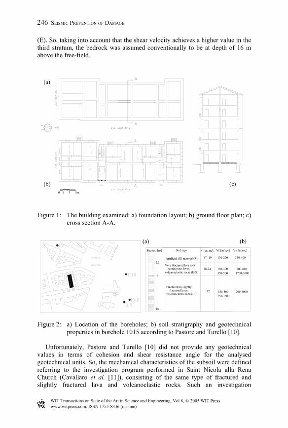
(E). So, taking into account that the shear velocity achieves a higher value in the third stratum, the bedrock was assumed conventionally to be at depth of 16 m above the free-field.
Figure 1: The building examined: a) foundation layout; b) ground floor plan; c)
cross section A-A.
Figure 2: a) Location of the boreholes; b) soil stratigraphy and geotechnical properties in borehole 1015 according to Pastore and Turello [10].
Unfortunately, Pastore and Turello [10] did not provide any geotechnical values in terms of cohesion and shear resistance angle for the analysed geotechnical units. So, the mechanical characteristics of the subsoil were defined referring to the investigation program performed in Saint Nicola alla Rena Church (Cavallaro et al. [11]), consisting of the same type of fractured and slightly fractured lava and volcanoclastic rocks. Such an investigation
0 1 3 5m
(a)
(c) (b)
Artificial fill material (R)
scoriaceous lavas,
Soil type Vs [m/sec][kN/m ]Stratum [m]
16
6
2.517 -19
fractured lavas
18-24
22
130-220
180-300
350-500
3γ
volcanoclastic rocks (E-X)
Very fractured lava rock
Fractured to slightly
volcanoclastic rocks (E)
350-400
1700-3000
700-800
Vp [m/sec]
350-500
750-1500
1700-3000
(a) (b)
246 SEISMIC PREVENTION OF DAMAGE
www.witpress.com, ISSN 1755-8336 (on-line) WIT Transactions on State of the Art in Science and Engineering, Vol 8, © 2005 WIT Press
represented in fact an attempt to provide a case record for seismic response analysis. So, the E-X and E units were characterized by a cohesion c' equal to 0 kPa and φ' equal to 28°-39° and in particular it was assumed that a resistance shear angle φ' was equal to 28° for the second stratum and φ' equal to 39° for the third one. As far as the dynamic properties of the subsoil are concerned, the relationships proposed by Cavallaro et al. [11] for Saint Nicola alla Rena Church area were considered. The law of the shear modulus G as well as the law of the damping ratio D were obtained on the basis of the dynamic laboratory tests, such as resonant column tests and torsional shear tests. The decrease of the soil shear modulus G and the decrease of the damping ratio D with the deformation level were expressed by the following laws:
897.00 5.71
1)(γ
γ⋅+
=G
G (1)
G
GD
⋅−⋅=
0
)(50.4exp90)(%)( γγ (2)
in which G(γ) is the strain dependent shear modulus, γ the current shear strain in percent, 7.5, 0.897, 90 and 4.50 are soil constants, D(γ) is the strain dependent damping ratio and G0 the initial shear modulus obtained for each stratum according to the relationship G0=ρ⋅Vs
2 in which ρ=γ/g.
2.3 Local site response
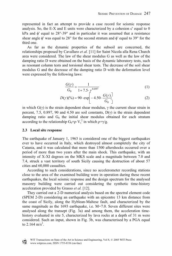
The earthquake of January 1, 1963 is considered one of the biggest earthquakes ever to have occurred in Italy, which destroyed almost completely the city of Catania, and it was calculated that more than 1500 aftershocks occurred over a period of more than two years after the main shock. This earthquake, with an intensity of X-XI degrees on the MKS scale and a magnitude between 7.0 and 7.4, struck a vast territory of south Sicily causing the destruction of about 57 cities and 60,000 casualties. According to such considerations, since no accelerometer recording stations close to the area of the examined building were in operation during these recent earthquakes, the local seismic response and the design spectrum for the analysed masonry building were carried out considering the synthetic time-history acceleration provided by Grasso et al. [12]. They carried out a 2-D numerical analysis based on the spectral element code (SPEM 2-D) considering an earthquake with an epicentre 13 km distance from the coast of Sicily, along the Hyblean-Maltese fault, and characterized by the same magnitude as the 1693 earthquake, i.e. M=7.0. Seven different sites were analysed along the transept (Fig. 3a) and among them, the acceleration time-history evaluated in site 5, characterized by lava rocks at a depth of 31 m were considered. Such an input, shown in Fig. 3b, was characterised by a PGA equal to 2.164 m/s2.
SEISMIC PREVENTION OF DAMAGE 247
www.witpress.com, ISSN 1755-8336 (on-line) WIT Transactions on State of the Art in Science and Engineering, Vol 8, © 2005 WIT Press
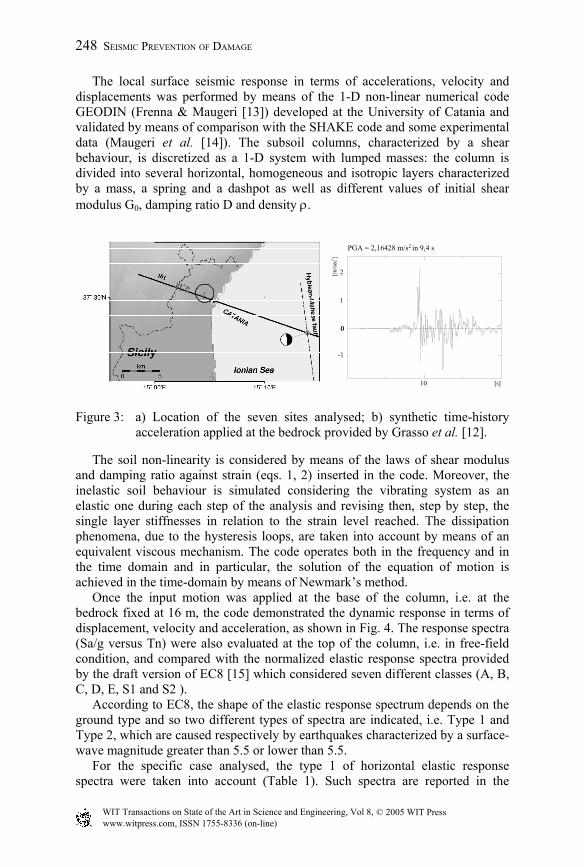
The local surface seismic response in terms of accelerations, velocity and displacements was performed by means of the 1-D non-linear numerical code GEODIN (Frenna & Maugeri [13]) developed at the University of Catania and validated by means of comparison with the SHAKE code and some experimental data (Maugeri et al. [14]). The subsoil columns, characterized by a shear behaviour, is discretized as a 1-D system with lumped masses: the column is divided into several horizontal, homogeneous and isotropic layers characterized by a mass, a spring and a dashpot as well as different values of initial shear modulus G0, damping ratio D and density ρ.
Figure 3: a) Location of the seven sites analysed; b) synthetic time-history acceleration applied at the bedrock provided by Grasso et al. [12].
The soil non-linearity is considered by means of the laws of shear modulus and damping ratio against strain (eqs. 1, 2) inserted in the code. Moreover, the inelastic soil behaviour is simulated considering the vibrating system as an elastic one during each step of the analysis and revising then, step by step, the single layer stiffnesses in relation to the strain level reached. The dissipation phenomena, due to the hysteresis loops, are taken into account by means of an equivalent viscous mechanism. The code operates both in the frequency and in the time domain and in particular, the solution of the equation of motion is achieved in the time-domain by means of Newmark’s method. Once the input motion was applied at the base of the column, i.e. at the bedrock fixed at 16 m, the code demonstrated the dynamic response in terms of displacement, velocity and acceleration, as shown in Fig. 4. The response spectra (Sa/g versus Tn) were also evaluated at the top of the column, i.e. in free-field condition, and compared with the normalized elastic response spectra provided by the draft version of EC8 [15] which considered seven different classes (A, B, C, D, E, S1 and S2 ). According to EC8, the shape of the elastic response spectrum depends on the ground type and so two different types of spectra are indicated, i.e. Type 1 and Type 2, which are caused respectively by earthquakes characterized by a surface-wave magnitude greater than 5.5 or lower than 5.5. For the specific case analysed, the type 1 of horizontal elastic response spectra were taken into account (Table 1). Such spectra are reported in the
-1
0 0
1
10
PGA = 2,16428 m/s in 9,4 s
2
248 SEISMIC PREVENTION OF DAMAGE
www.witpress.com, ISSN 1755-8336 (on-line) WIT Transactions on State of the Art in Science and Engineering, Vol 8, © 2005 WIT Press
Eurocode in terms of: Se (T), i.e. the ordinate of the elastic response spectrum; T, i.e. the vibration period of a linear single degree of freedom system where in particular TB and TC are the initial and final abscissas of limits of the spectrum plateau, TD is the value defining the beginning of the constant displacement response range of the spectrum and: S, i.e. a soil factor; ag, i.e. the design ground acceleration, η; i.e. the damping correction factor expressed as:
55.0)5/(10 . ≥+= strξη (3) where ξstr ranges generally between 2%-5% for reinforced concrete buildings and between 5%-10% for masonry buildings and assumed to be equal to 10% for the specific masonry building analysed.
Figure 4: Time-histories in terms of displacement, velocity and acceleration in free-field conditions.
Table 1: Values of the parameters for Type 1 elastic response spectrum.
Ground type S TB TC TD
A 1.00 0.15 0.4 2.0 B 1.20 0.15 0.5 2.0 C 1.15 0.20 0.6 2.0 D 1.35 0.20 0.8 2.0 E 1.40 0.15 0.5 2.0
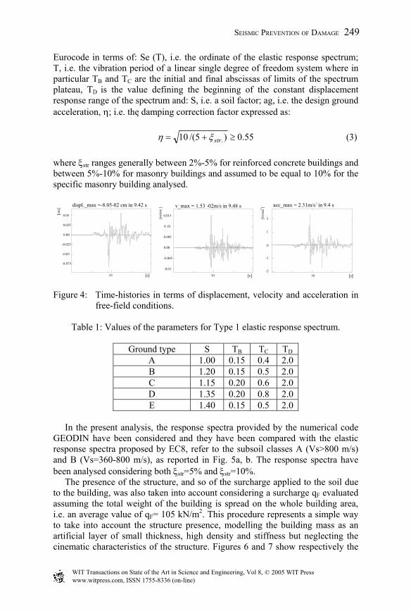
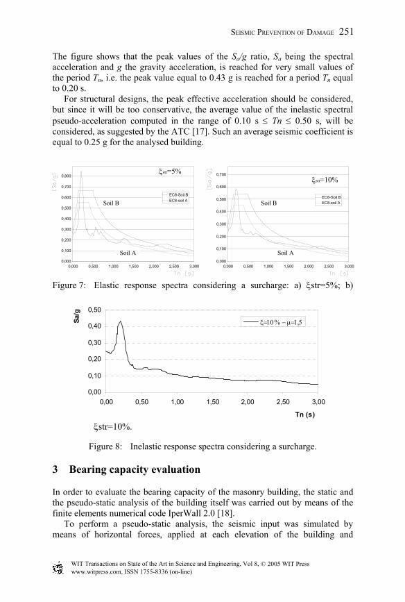
In the present analysis, the response spectra provided by the numerical code GEODIN have been considered and they have been compared with the elastic response spectra proposed by EC8, refer to the subsoil classes A (Vs>800 m/s) and B (Vs=360-800 m/s), as reported in Fig. 5a, b. The response spectra have been analysed considering both ξstr=5% and ξstr=10%. The presence of the structure, and so of the surcharge applied to the soil due to the building, was also taken into account considering a surcharge qF evaluated assuming the total weight of the building is spread on the whole building area, i.e. an average value of qF= 105 kN/m2. This procedure represents a simple way to take into account the structure presence, modelling the building mass as an artificial layer of small thickness, high density and stiffness but neglecting the cinematic characteristics of the structure. Figures 6 and 7 show respectively the
v_max = 1.53 -02m/s in 9.48 s
-0.005
-0.01
0.00
0.005
0 .01
0.015
10-2
-1
0
10
acc_max = 2.31m/s in 9.4 s
1
2
displ._max =-8.05-02 cm in 9.42 s
-0.075
-0.05
-0.025
0.00
0.025
0.05
10
SEISMIC PREVENTION OF DAMAGE 249
www.witpress.com, ISSN 1755-8336 (on-line) WIT Transactions on State of the Art in Science and Engineering, Vol 8, © 2005 WIT Press
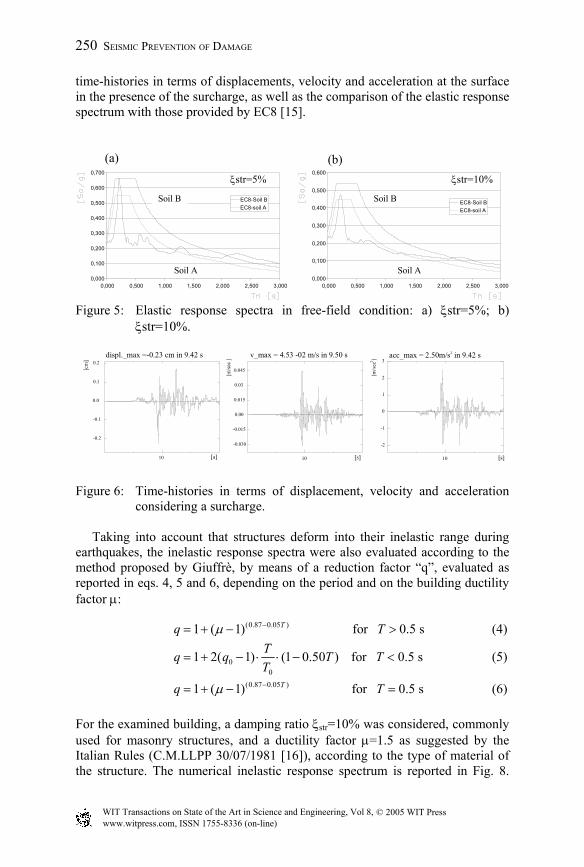
time-histories in terms of displacements, velocity and acceleration at the surface in the presence of the surcharge, as well as the comparison of the elastic response spectrum with those provided by EC8 [15].
Figure 5: Elastic response spectra in free-field condition: a) ξstr=5%; b) ξstr=10%.
Figure 6: Time-histories in terms of displacement, velocity and acceleration
considering a surcharge. Taking into account that structures deform into their inelastic range during earthquakes, the inelastic response spectra were also evaluated according to the method proposed by Giuffrè, by means of a reduction factor “q”, evaluated as reported in eqs. 4, 5 and 6, depending on the period and on the building ductility factor µ:
(0.87 0.05 )1 ( 1) for 0.5 sTq Tµ −= + − > (4)
00
1 2( 1) (1 0.50 ) for 0.5 sTq q T TT
= + − ⋅ ⋅ − < (5)
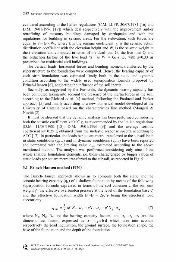
(0.87 0.05 )1 ( 1) for 0.5 sTq Tµ −= + − = (6) For the examined building, a damping ratio ξstr=10% was considered, commonly used for masonry structures, and a ductility factor µ=1.5 as suggested by the Italian Rules (C.M.LLPP 30/07/1981 [16]), according to the type of material of the structure. The numerical inelastic response spectrum is reported in Fig. 8.
-0.2
-0.1
0.0
0.1
0.2
10
-0.030
-0.015
0.00
0.015
0.03
0.045
10
-2
0
-1
1
2
3
10
displ._max =-0.23 cm in 9.42 s v_max = 4.53 -02 m/s in 9.50 s acc_max = 2.50m/s in 9.42 s
ξstr=5% ξstr=10%
0,000
0,100
0,200
0,300
0,400
0,500
0,600
0,700
0,000 0,500 1,000 1,500 2,000 2,500 3,000
EC8-Soil BEC8-soil A
0,000
0,100
0,200
0,300
0,400
0,500
0,600
0,000 0,500 1,000 1,500 2,000 2,500 3,000
EC8-Soil BEC8-soil A
(a) (b)
Soil B
Soil A
Soil B
Soil A
250 SEISMIC PREVENTION OF DAMAGE
www.witpress.com, ISSN 1755-8336 (on-line) WIT Transactions on State of the Art in Science and Engineering, Vol 8, © 2005 WIT Press
The figure shows that the peak values of the Sa/g ratio, Sa being the spectral acceleration and g the gravity acceleration, is reached for very small values of the period Tn, i.e. the peak value equal to 0.43 g is reached for a period Tn equal to 0.20 s. For structural designs, the peak effective acceleration should be considered, but since it will be too conservative, the average value of the inelastic spectral pseudo-acceleration computed in the range of 0.10 s ≤ Tn ≤ 0.50 s, will be considered, as suggested by the ATC [17]. Such an average seismic coefficient is equal to 0.25 g for the analysed building.
Figure 7: Elastic response spectra considering a surcharge: a) ξstr=5%; b)
ξstr=10%.
Figure 8: Inelastic response spectra considering a surcharge.
3 Bearing capacity evaluation
In order to evaluate the bearing capacity of the masonry building, the static and the pseudo-static analysis of the building itself was carried out by means of the finite elements numerical code IperWall 2.0 [18]. To perform a pseudo-static analysis, the seismic input was simulated by means of horizontal forces, applied at each elevation of the building and
0,00
0,10
0,20
0,30
0,40
0,50
0,00 0,50 1,00 1,50 2,00 2,50 3,00
Tn (s)
Sa/g
ξ=10 % − µ=1,5
0,500
3,0002,5002,0001,5001,0000,5000,0000,000
0,300
0,100
0,200
0,400
0,000 0,500 1,000 1,500 2,000 2,500 3,0000,000
0,100
0,200
0,300
EC8-Soil B0,600
EC8-soil A
0,700
0,800
EC8-Soil B
0,400
EC8-soil A0,500
0,600
0,700ξstr=5%ξstr=10%
Soil B
Soil A
Soil B
Soil A
SEISMIC PREVENTION OF DAMAGE 251
www.witpress.com, ISSN 1755-8336 (on-line) WIT Transactions on State of the Art in Science and Engineering, Vol 8, © 2005 WIT Press
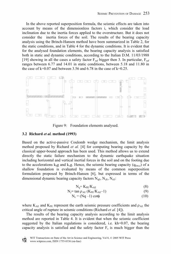
evaluated according to the Italian regulations (C.M. LLPP. 30/07/1981 [16] and D.M. 19/01/1996 [19]) which deal respectively with the improvement and/or retrofitting of masonry buildings damaged by earthquake and with the regulations for building in seismic areas. For the i-elevation, such forces are equal to Fi= k·γi·Wi, where k is the seismic coefficient, γi is the seismic action distribution coefficient with the elevation height and Wi is the seismic weight at the i-elevation and computed in terms of the dead load Gi, the live load Qi and the reduction factors of the live load “s” as Wi = Gi+s Qi, with s=0.33 as prescribed for residential civil buildings. The vertical loads, horizontal forces and bending moment transferred by the superstructure to the foundation were computed. Hence, the bearing capacity of each strip foundation was estimated firstly both in the static and dynamic condition according to the widely used superposition formula proposed by Brinch-Hansen [6], neglecting the influence of the soil inertia. Secondly, as suggested by the Eurocode, the dynamic bearing capacity has been computed taking into account the presence of the inertia forces in the soil, according to the Richard et al. [4] method, following the Paolucci and Pecker approach [5] and finally according to a new numerical model developed at the University of Catania based on the characteristics line method (Maugeri & Novità [2]. It must be stressed that the dynamic analysis has been performed considering both the seismic coefficient k=0.07 g, as recommended by the Italian regulations (D.M. 11/03/1988 [18]; D.M. 19/01/1996 [9]) and the average seismic coefficient k= 0.25 g obtained from the inelastic response spectra according to ATC [17]. In particular, the loads per square metre transferred to the subsoil both in static conditions (qact,s) and in dynamic conditions (qact,e) have been reported and compared with the limiting value qlim estimated according to the above mentioned method. The analysis was performed considering only nine of the whole shallow foundation elements, i.e. those characterized by bigger values of static loads per square metre transferred to the subsoil, as reported in Fig. 9.
3.1 Brinch-Hansen method (1970)
The Brinch-Hansen approach allows us to compute both the static and the seismic bearing capacity (qL) of a shallow foundation by means of the following superposition formula expressed in terms of the soil cohesion c, the soil unit weight γ′, the effective overburden pressure at the level of the foundation base q′ and the effective foundation width B′=B – 2e, e being the structural load eccentricity:
NqcNNBq qqcc αααγ γγ ⋅+⋅+⋅= ''21
lim (7)
where Nc, Nq, Nγ are the bearing capacity factors, and αc, αq, αγ are the dimensionless factors expressed as α= i⋅g⋅s⋅b⋅d which take into account respectively the load inclination, the ground surface, the foundation shape, the base of the foundation and the depth of the foundation.
252 SEISMIC PREVENTION OF DAMAGE
www.witpress.com, ISSN 1755-8336 (on-line) WIT Transactions on State of the Art in Science and Engineering, Vol 8, © 2005 WIT Press
In the above reported superposition formula, the seismic effects are taken into account by means of the dimensionless factors i, which consider the load inclination due to the inertia forces applied to the overstructure. But it does not consider the inertia forces of the soil. The results of the bearing capacity analysis using the Brinch-Hansen method have been summarized in Table 2, for the static conditions, and in Table 4 for the dynamic conditions. It is evident that for the analysed foundation elements, the bearing capacity analysis is satisfied both in static and dynamic conditions, according to the Italian D.M. 11/03/1988 [19] showing in all the cases a safety factor Fsaf bigger then 3. In particular, Fsaf ranges between 6.77 and 14.01 in static conditions, between 5.18 and 11.80 in the case of k=0.07 and between 3.56 and 6.78 in the case of k=0.25.
Figure 9: Foundation elements analysed.
3.2 Richard et al. method (1993)
Based on the active-passive Coulomb wedge mechanism, the limit analysis method proposed by Richard et al. [4] for computing bearing capacity by the classical upper-bound approach has been used. This method allows us to extend directly the static failure mechanism to the dynamic earthquake situation including horizontal and vertical inertial forces in the soil and on the footing due to the accelerations khg and kvg. Hence, the seismic bearing capacity (qlim,e) of a shallow foundation is evaluated by means of the common superposition formulation proposed by Brinch-Hansen [6], but expressed in terms of the dimensional dynamic bearing capacity factors NqE, NγE, NcE:
Nq= KPE/KAE (8)
Nγ= tan ρAE (KPE/KAE–1) (9) Nc = (Nq –1) cotφ (10) where KAE and KPE represent the earth seismic pressure coefficients and ρAE the critical angle of rupture in seismic conditions (Richard et al. [4]). The results of the bearing capacity analysis according to the limit analysis method are reported in Table 4. It is evident that when the seismic coefficient suggested by the Italian regulations is considered, i.e. kh=0.07, the bearing capacity analysis is satisfied and the safety factor Fs is much bigger than the
SEISMIC PREVENTION OF DAMAGE 253
www.witpress.com, ISSN 1755-8336 (on-line) WIT Transactions on State of the Art in Science and Engineering, Vol 8, © 2005 WIT Press
recommended one, ranging between 3.78 and 8.30 respectively for elements 48 and 54. On the other hand, when the average seismic coefficient k= 0.25 g is considered, the safety factor ranges between 1.33 and 2.78, again for the same elements.
Table 2: Static bearing capacity.
Static condition Foundations Brinch-Hansen
Walls L B D qact,st qlim,st Fs,st [m] [m] [m] [Mpa] [Mpa]
29 2.89 1.10 2.50 0.38 3.50 9.21 30 1.89 1.10 2.50 0.38 3.80 10.00 46 1.38 0.90 2.50 0.55 4.13 7.51 47 1.22 0.90 2.50 0.54 4.27 7.91 48 6.81 0.90 2.50 0.53 3.28 6.80 51 1.21 0.90 2.50 0.50 4.28 8.57 54 3.53 0.90 2.50 0.25 3.48 13.92 63 1.11 1.10 2.50 0.50 4.41 8.80 66 12.10 0.90 2.50 0.47 3.18 6.77
3.3 Paolucci and Pecker method (1997)
The kinematic approach of the yield design theory mechanism, proposed by Paolucci and Pecker [5] to determine the best upper bound approximation for the limit load, has been adopted to compute the bearing capacity of shallow foundations due to the seismic actions transmitted by both the overstructure and the soil inertia. According to the kinematic mechanism, which is a Prandtl type, the bearing capacity reduction factor v due respectively to load eccentricity (ve), to the inertia of the soil (vi) and to the effect of load inclination (vh) that describes the influence of the horizontal load transmitted by the loading superstructure, is given by the following expression:
v= ve· vi· vh = 0.351.8 321 1 1
tan 0.85h he k k
B φ ⋅ − ⋅ − ⋅ −
(11)
Hence, seismic bearing capacity is obtained multiplying the static bearing capacity by the reduction factor v. The results of the bearing capacity analysis reported in Table 4 show that when the analysis is performed considering a seismic coefficient kh=0.07, the safety factor Fs ranges between 4.25 and 8.76 respectively for elements 48 and
254 SEISMIC PREVENTION OF DAMAGE
www.witpress.com, ISSN 1755-8336 (on-line) WIT Transactions on State of the Art in Science and Engineering, Vol 8, © 2005 WIT Press
54, and so for the same foundation elements considered with the Richard et al. [4] approach. Hence, the bearing capacity analysis is well satisfied. Otherwise, the safety factor Fs ranges between 1.46 and 2.38, respectively for elements 48 and 54, when the average seismic coefficient k=0.25 g is used.
3.4 Characteristics line method of the limiting equilibrium (2004)
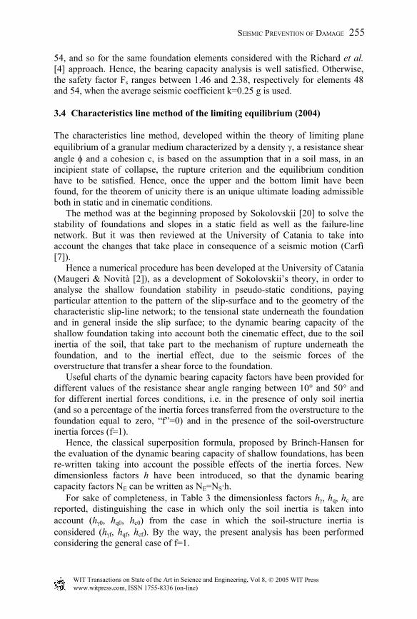
The characteristics line method, developed within the theory of limiting plane equilibrium of a granular medium characterized by a density γ, a resistance shear angle φ and a cohesion c, is based on the assumption that in a soil mass, in an incipient state of collapse, the rupture criterion and the equilibrium condition have to be satisfied. Hence, once the upper and the bottom limit have been found, for the theorem of unicity there is an unique ultimate loading admissible both in static and in cinematic conditions. The method was at the beginning proposed by Sokolovskii [20] to solve the stability of foundations and slopes in a static field as well as the failure-line network. But it was then reviewed at the University of Catania to take into account the changes that take place in consequence of a seismic motion (Carfì [7]). Hence a numerical procedure has been developed at the University of Catania (Maugeri & Novità [2]), as a development of Sokolovskii’s theory, in order to analyse the shallow foundation stability in pseudo-static conditions, paying particular attention to the pattern of the slip-surface and to the geometry of the characteristic slip-line network; to the tensional state underneath the foundation and in general inside the slip surface; to the dynamic bearing capacity of the shallow foundation taking into account both the cinematic effect, due to the soil inertia of the soil, that take part to the mechanism of rupture underneath the foundation, and to the inertial effect, due to the seismic forces of the overstructure that transfer a shear force to the foundation. Useful charts of the dynamic bearing capacity factors have been provided for different values of the resistance shear angle ranging between 10° and 50° and for different inertial forces conditions, i.e. in the presence of only soil inertia (and so a percentage of the inertia forces transferred from the overstructure to the foundation equal to zero, “f”=0) and in the presence of the soil-overstructure inertia forces (f=1). Hence, the classical superposition formula, proposed by Brinch-Hansen for the evaluation of the dynamic bearing capacity of shallow foundations, has been re-written taking into account the possible effects of the inertia forces. New dimensionless factors h have been introduced, so that the dynamic bearing capacity factors NE can be written as NE=NS·h. For sake of completeness, in Table 3 the dimensionless factors hγ, hq, hc are reported, distinguishing the case in which only the soil inertia is taken into account (hγ0, hq0, hc0) from the case in which the soil-structure inertia is considered (hγf, hqf, hcf). By the way, the present analysis has been performed considering the general case of f=1.
SEISMIC PREVENTION OF DAMAGE 255
www.witpress.com, ISSN 1755-8336 (on-line) WIT Transactions on State of the Art in Science and Engineering, Vol 8, © 2005 WIT Press
The results of the bearing capacity analysis according to the characteristics line method are reported in Table 4. Once again the foundation elements satisfy the seismic bearing capacity when it is performed according to the Italian Regulations, i.e. Fs ranges between 4.28 and 9.40 respectively for elements 48 and 54, whereas it ranges between 1.65 and 3.45 when kh=0.025. Table 3: Dynamic bearing capacity factors according to the characteristics line
method.
γγγ hNN SE ⋅=
Soil inertia (f=0)
10, +⋅= hkAhγ
41.5tan23.15tan59.18tan17.7 23 −⋅+⋅−⋅= φφφA Soil-structure
inertia (f=1)
1)()( 2, +⋅⋅+⋅⋅= fkCfkBh hhfγ
8.24tan4.74tan60.86tan1.32 23 +⋅−⋅+⋅−= φφφB
48.12tan28.30tan067.35tan90.12 23 −⋅+⋅−⋅= φφφC
ccScE hNN ⋅=
Soil inertia (f=0)
hc,0 = 1
Soil-structure inertia (f=1)
1)()( 2, +⋅⋅+⋅⋅= fkEfkDh hhfc
61.29tan129tan173tan06.70 23 −⋅+⋅−⋅= φφφD 07.1tan27.1 −⋅−= φE
qqSqE hNN ⋅= Soil inertia
(f=0) 12
0, +⋅+⋅= KhGKhFhq
96.19tan81tan2.107tan43 23 −⋅+⋅−⋅= φφφF
35.0tan61.4tan66.6tan8.2 23 +⋅−⋅+⋅−= φφφG Soil-structure
inertia (f=1)
1)()( 2, +⋅⋅+⋅⋅= fkIfkHh hhfq
99.25tan116tan14.155tan69.63 23 −⋅+⋅−⋅= φφφH
23.0tan5.8tan57.10tan48.4 23 −⋅−⋅+⋅−= φφφI
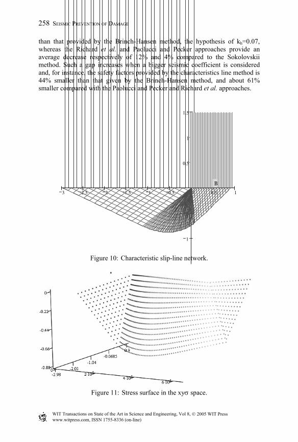
Referring to the foundation element n. 48, the slip-surface and the characteristic slip-line network has been reported in Fig. 10, as well as the stress surface in the xyσ space (Fig. 11). The failure surface is characterized by a length of 2.98 m and maximum depth of 0.88 m.
256 SEISMIC PREVENTION OF DAMAGE
www.witpress.com, ISSN 1755-8336 (on-line) WIT Transactions on State of the Art in Science and Engineering, Vol 8, © 2005 WIT Press
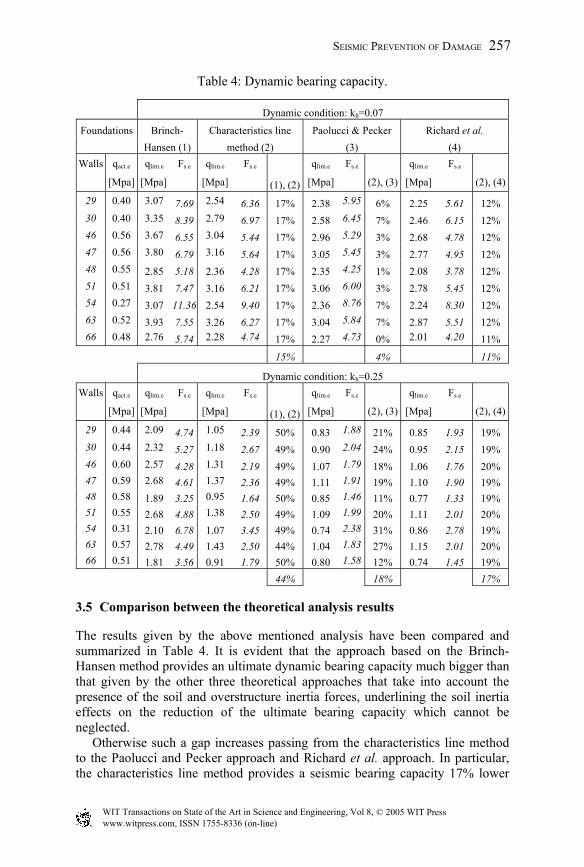
Table 4: Dynamic bearing capacity.
Dynamic condition: kh=0.07
Foundations Brinch- Characteristics line Paolucci & Pecker Richard et al. Hansen (1) method (2) (3) (4)
Walls qact.e qlim.e Fs.e qlim.e Fs.e qlim.e Fs.e qlim.e Fs.e
[Mpa] [Mpa] [Mpa] (1), (2) [Mpa] (2), (3) [Mpa] (2), (4)
29 0.40 3.07 7.69 2.54 6.36 17% 2.38 5.95 6% 2.25 5.61 12% 30 0.40 3.35 8.39 2.79 6.97 17% 2.58 6.45 7% 2.46 6.15 12% 46 0.56 3.67 6.55 3.04 5.44 17% 2.96 5.29 3% 2.68 4.78 12% 47 0.56 3.80 6.79 3.16 5.64 17% 3.05 5.45 3% 2.77 4.95 12% 48 0.55 2.85 5.18 2.36 4.28 17% 2.35 4.25 1% 2.08 3.78 12% 51 0.51 3.81 7.47 3.16 6.21 17% 3.06 6.00 3% 2.78 5.45 12% 54 0.27 3.07 11.36 2.54 9.40 17% 2.36 8.76 7% 2.24 8.30 12% 63 0.52 3.93 7.55 3.26 6.27 17% 3.04 5.84 7% 2.87 5.51 12% 66 0.48 2.76 5.74 2.28 4.74 17% 2.27 4.73 0% 2.01 4.20 11%
15% 4% 11%
Dynamic condition: kh=0.25 Walls qact.e qlim.e Fs.e qlim.e Fs.e qlim.e Fs.e qlim.e Fs.e
[Mpa] [Mpa] [Mpa] (1), (2) [Mpa] (2), (3) [Mpa] (2), (4)
29 0.44 2.09 4.74 1.05 2.39 50% 0.83 1.88 21% 0.85 1.93 19% 30 0.44 2.32 5.27 1.18 2.67 49% 0.90 2.04 24% 0.95 2.15 19% 46 0.60 2.57 4.28 1.31 2.19 49% 1.07 1.79 18% 1.06 1.76 20% 47 0.59 2.68 4.61 1.37 2.36 49% 1.11 1.91 19% 1.10 1.90 19% 48 0.58 1.89 3.25 0.95 1.64 50% 0.85 1.46 11% 0.77 1.33 19% 51 0.55 2.68 4.88 1.38 2.50 49% 1.09 1.99 20% 1.11 2.01 20% 54 0.31 2.10 6.78 1.07 3.45 49% 0.74 2.38 31% 0.86 2.78 19% 63 0.57 2.78 4.49 1.43 2.50 44% 1.04 1.83 27% 1.15 2.01 20% 66 0.51 1.81 3.56 0.91 1.79 50% 0.80 1.58 12% 0.74 1.45 19%
44% 18% 17%
3.5 Comparison between the theoretical analysis results
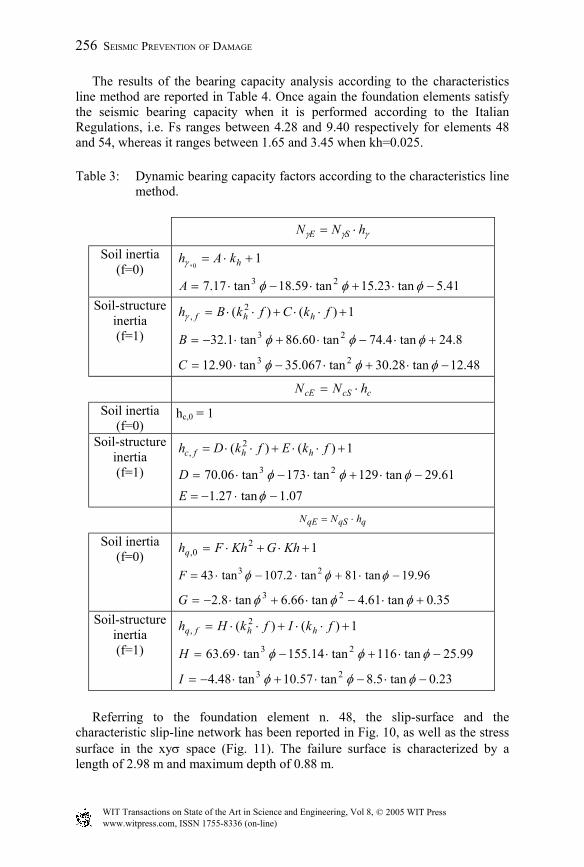
The results given by the above mentioned analysis have been compared and summarized in Table 4. It is evident that the approach based on the Brinch-Hansen method provides an ultimate dynamic bearing capacity much bigger than that given by the other three theoretical approaches that take into account the presence of the soil and overstructure inertia forces, underlining the soil inertia effects on the reduction of the ultimate bearing capacity which cannot be neglected. Otherwise such a gap increases passing from the characteristics line method to the Paolucci and Pecker approach and Richard et al. approach. In particular, the characteristics line method provides a seismic bearing capacity 17% lower
SEISMIC PREVENTION OF DAMAGE 257
www.witpress.com, ISSN 1755-8336 (on-line) WIT Transactions on State of the Art in Science and Engineering, Vol 8, © 2005 WIT Press
than that provided by the Brinch-Hansen method, the hypothesis of kh=0.07, whereas the Richard et al. and Paolucci and Pecker approaches provide an average decrease respectively of 12% and 4% compared to the Sokolovskii method. Such a gap increases when a bigger seismic coefficient is considered and, for instance, the safety factors provided by the characteristics line method is 44% smaller than that given by the Brinch-Hansen method, and about 61% smaller compared with the Paolucci and Pecker and Richard et al. approaches.
Figure 10: Characteristic slip-line network.
Figure 11: Stress surface in the xyσ space.
3 2.5 2 1.5 1 0.5 0 0.5 1
1
0.5
0.5
1
1.5
B
258 SEISMIC PREVENTION OF DAMAGE
www.witpress.com, ISSN 1755-8336 (on-line) WIT Transactions on State of the Art in Science and Engineering, Vol 8, © 2005 WIT Press
Hence, among the approaches adopted, Richard et al. appears to be the more conservative, whereas the difference between the results provided by the characteristics line method and the Paolucci and Pecker approach are quite negligible (about 4% when kh=0.07). This could be due to the fact that the Coulomb-type mechanism developed by Richard et al. for the shallow foundation is an adaptation of the Mononobe-Okabe analysis of retaining wall to the footing. Besides, regarding the seismic safety factor, it must be stressed that the Italian Regulation concerning building design in seismic areas (D.M. 19/01/1996 [9]) does not define a minimum value of the seismic safety factor. Generally the minimum value of the safety factor Fs, st= 3, reported in the D.M. 11/03/1988 [19] is used, but this leads to a too conservative design.
4 Conclusion
The static and pseudo-static bearing capacity verifications represent an important starting point for every comprehensive building improvement and/or retrofitting. In the present paper, the dynamic bearing capacity analysis of the shallow foundation of a full-scale masonry building was performed, on the basis of the dynamic characterisation of the subsoil (Pastore & Turello [10]; Cavallaro et al.[11]) and of the local site response performed by means of the 1-D non-linear numerical code GEODIN (Frenna & Maugeri [13]). Firstly, the foundation behaviour was analysed considering the inelastic spectrum suggested by the Italian Rules (D.M 19/01/1996 [9]), i.e. the seismic coefficient recommended for the second seismic category. Secondly, the local seismic response and the design inelastic spectrum for the analysed masonry building were evaluated considering the synthetic time-history acceleration referred to following the destructive earthquake of 1693 (Grasso et al., [12]). Hence the analysis was performed considering the average value of the inelastic spectral pseudo-acceleration according to ATC ([17]. The ultimate loading was previously computed according to the worldwide used Brinch-Hansen method [6]. Then, for the pseudo-static conditions, according to the suggestions of EC8 [3], the soil inertia effects were also taken into account, considering that, even if EC8 recommends the inclusion of the soil inertia effect, it does not give any indication for the computing of this effect. To this aim, a new numerical model based on the characteristics method line (Maugeri & Novità [2]) which allows us to evaluate the seismic bearing capacity considering the effects of the inertia forces in the supporting soil as well as the effect of the inertia forces of the structure, was used. The results of the analysis were compared with those provided by two other recent approaches which take also into account the soil inertia effect on the seismic bearing capacity reduction, i.e. Richard et al. method [4] and Paolucci and Pecker method [5]. As regards the bearing capacity analysis, it must be underlined that while in static conditions, the allowable bearing capacity criterion suggested by the Italian geotechnical D.M. 11/03/1988 [19] was adopted, for the pseudo-static conditions, the Italian Regulation criterion (C.M. LL.PP. 30/07/1981 [16],
SEISMIC PREVENTION OF DAMAGE 259
www.witpress.com, ISSN 1755-8336 (on-line) WIT Transactions on State of the Art in Science and Engineering, Vol 8, © 2005 WIT Press
D.M. 11/03/1988 [19] and D.M. 19/01/1996 [9]) is quite questionable, because it does not clearly establish a minimum value of the seismic safety factor FSE. In reality the estimation of an appropriate minimum value of FSE is strongly dependent on the estimation of the seismic coefficient k, which is linked to the soil amplification. The greater the value of k, the greater the reduction of the bearing capacity, due to the effects of the inclination of the loads transferred by the superstructure to the foundation, due to the eventual eccentricity of the vertical loads and, above all, due to the soil effect (Grasso et al. 2001 [21]). For the examined masonry building, on the basis of seismic ground motion response analysis, a value of the seismic coefficient much greater than those reported by the Italian Regulation, and equal to 0.25, was considered. Finally a comparison between the safety factors provided by the different approaches were compared, underlining how the soil inertia effects on the reduction of the ultimate bearing capacity is a phenomenon that cannot be neglected, since it causes a deep decrease of the ultimate loading, compared to that provided by the classical Brinch-Hansen method. According to some authors the soil inertia effects may be disregarded if the foundation is designed with a safety factor that is sufficiently high, i.e. FSE≥2.5 (Paolucci & Pecker [5]), but this means that it is necessary to perform first a more realistic dynamic analysis of the building taking into account the subsoil and also the design inelastic spectrum for the examined building, since often the inelastic spectrum suggested by the Italian Rules was not realistic. In fact, for the analysed building, if the seismic coefficient recommended by the Italian regulation is considered, the shallow foundation does not need any remedial work, since the safety factor is always bigger than three, whereas when the design inelastic spectrum is considered, the safety factor became much smaller, and in any case becomes smaller than three.
References
[1] Maugeri, M., Castelli, F., Massimino, M.R. & Verona, G. (1998): Observed and computed settlements of two shallow foundations on sand. J. Geotech. And Geoenv. Engng. Div., ASCE, 124(7), 595-605.
[2] Maugeri, M. & Novità, D. (2004): Numerical model for the evaluation of the effects of soil-structure interaction shallow foundation bearing capacity. Proc. in XIth Int. Conf. Soil Dynam. and Earth. Eng.,(XI ICSDEE), University of California, Berkley.
[3] EC8 (1998): Design provisions for earthquake resistance of structures – Part 5: Foundations, retaining structures and geotechnical aspects. European Prestandard, ENV 1998, European Committee for Standardization, Brussels, Belgium.
[4] Richard, R., Elms, D.G. & Budhu, M. (1993): Seismic bearing capacity and settlements of foundations, Journal of Geotechnical Engineering, Vol. 119, No.4, April, pp. 662-674.
[5] Paolucci, R. & Pecker, A. (1997): Seismic bearing capacity of shallow strip foundation on dry soils, Soils and Foundations, Vol. 37, No. 3, pp. 95-105.
260 SEISMIC PREVENTION OF DAMAGE
www.witpress.com, ISSN 1755-8336 (on-line) WIT Transactions on State of the Art in Science and Engineering, Vol 8, © 2005 WIT Press
[6] Brinch-Hansen, J. (1970): A revised and extended formula for bearing capacity”, Danish Geotechnical Inst. Bull., 28 pp. 5-11.
[7] Carfì, G. (1998): Il carico limite di fondazione superficiali in condizioni dinamiche con il metodo delle caratteristiche”, Degree Thesis, University of Catania (in Italian).
[8] EC7 (1994): Geotechnical Design - Part 1: General Rules. European Prestandard, ENV 1994, European Committee for Standardization, Brussels, Belgium.
[9] D.M. 19 January 1996 (1996): Norme tecniche relative alle costruzioni sismiche. Supplemento alla Gazzetta Ufficiale della Repubblica Italiana n.29, 05.01.1996, Rome.
[10] Pastore, V. & Turello, R. (2000): Geotechnical zoning of the urban area of Catania for earthquake engineering purposes. In: The Catania Project: Earthquake Damage Scenarios for a high risk area in the Mediterranean. Faccioli and Pessina. CNR-GNDT. Rome, pp. 23-30.
[11] Cavallaro A., Grasso S. & Maugeri M. (2001): A dynamic geotechnical characterization of soil at Saint Nicola alla Rena Church damaged by the South Eastern Sicily Earthquake of 13 December 1990. Proc. in 15th Int. Conf. on Soil Mechanics and Geotechnical Engineering, Satellite Conference Lessons Learned from Recent Strong Earthquakes, Istanbul, 25 August 2001, pp. 243-248.
[12] Grasso, S., Laurenzano, G., Maugeri, M. & Priolo, E. (2004): Seismic response in Catania by different methodologies. Proc. Detailed Scenarios and Actions for Seismic Prevention of Damage in the Urban Area of Catania, This Volume, Chapter 4, WIT Press, Southampton.
[13] Frenna, S. M. & Maugeri, M. (1995): Il codice di calcolo GEODIN per l’analisi della risposta dinamica dei terreni. Proc. IX Convegno Italiano di Meccanica Computazionale. Catania, 20-22 June, 1995, pp. 145-148a.
[14] Maugeri, M., Carrubba, P. & Frenna S.M. (1988): Vibration mode and predominant frequency of heterogeneous soil. Italian Geotechnical Journal, Vol. XXII, n. 3, pp. 163-171 (in Italian).
[15] EC8 (2002): Design of structures for Earthquake Resistance - Part 1: General Rules, seismic actions and rules for building. European Committee for Standardization, CEN, Draft n.5.
[16] C.M.LLPP 30 July 1981 (1981) n. 21745: Istruzioni relative alla normativa tecnica per la riparazione ed il rafforzamento degli edifici in muratura danneggiati dal sisma.
[17] ATC (1978): Applied Technology Council - Tentative provisions for the development of seismic regulations for building, ATC Publ. ATC3-06, Spec. Publ. 510, U.S. Govern. Print. Off. Washington.
[18] IperWall 2.0: “ Verifica di Edifici in muratura e misti”, Sof. Lab. (Software Partnership).
[19] D.M. 11 March 1988 (1988): Norme tecniche riguardanti le indagini sui terreni e sulle rocce, la stabilità dei pendii naturali e delle scarpate, i criteri generali e le prescrizioni per la progettazione, l’esecuzione ed il collaudo
SEISMIC PREVENTION OF DAMAGE 261
www.witpress.com, ISSN 1755-8336 (on-line) WIT Transactions on State of the Art in Science and Engineering, Vol 8, © 2005 WIT Press
delle terre e delle opere di fondazione. Suppl. Gazzetta Ufficiale Repubblica Italiana n.127.
[20] Sokolovskii, V.V. (1965): Statics of Granular Media, translated by J.K. Lusher, Pergamon Press, 1965.
[21] Grasso, M., Massimino, M.R. & Maugeri, M. (2001): Remedial works on the foundation of masonry buildings in Sellano. Italian Geotechnical Journal, Special Issue, “The 1997-1998 Umbria–Marche earthquake”, Vol. XXXV, N.s 2 and 4, 122-141.
262 SEISMIC PREVENTION OF DAMAGE
www.witpress.com, ISSN 1755-8336 (on-line) WIT Transactions on State of the Art in Science and Engineering, Vol 8, © 2005 WIT Press