Chapter 11 – Magnetic Circuits Lecture 5 by Moeen Ghiyas 23/10/2015 1.
46
Chapter 11 – Magnetic Circuits Lecture 5 by Moeen Ghiyas 15/03/22 1
Transcript of Chapter 11 – Magnetic Circuits Lecture 5 by Moeen Ghiyas 23/10/2015 1.
Chapter 11 ndash Magnetic Circuits
Lecture 5
by Moeen Ghiyas
200423 1
Review
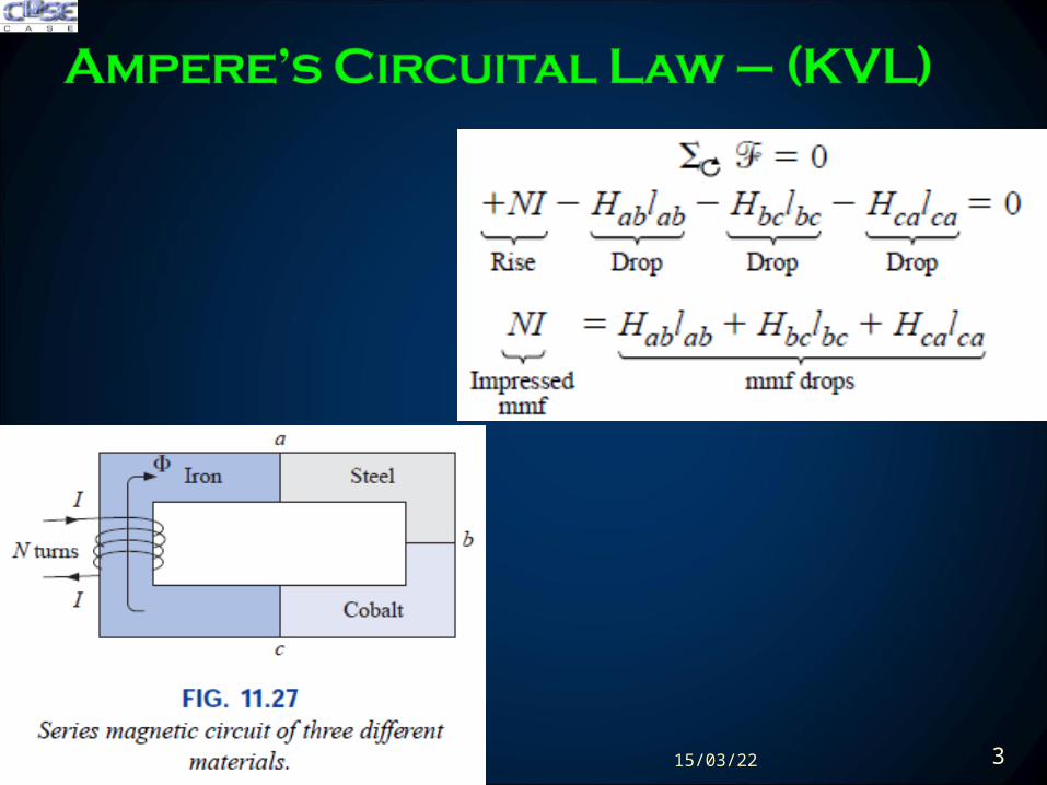
Amperersquos Circuital Law ndash (Applying KVL)
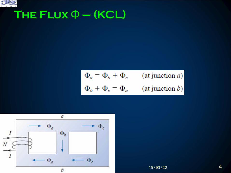
The Flux Φ ndash (Applying KCL)
Series Magnetic Circuits
Air Gaps
Series-Parallel Magnetic Circuits
Determining Flux Φ
Applications
200423 3
200423 4
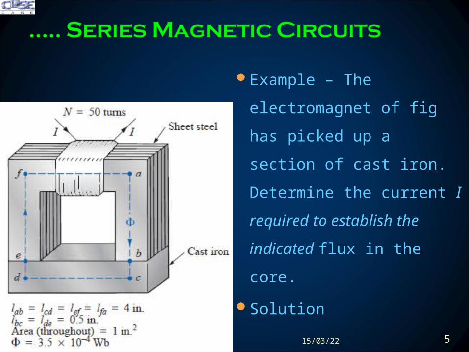
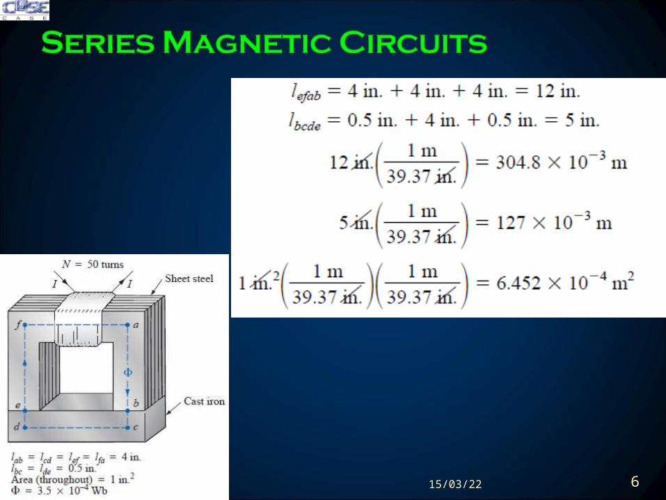
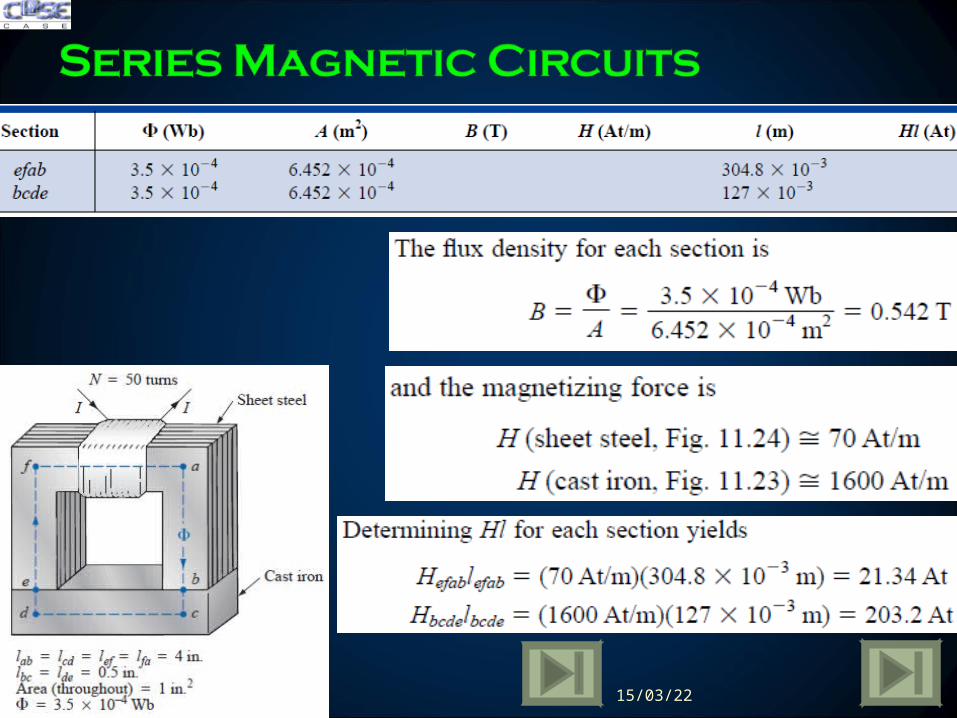
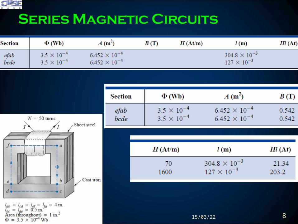
Example ndash The electromagnet
of fig has picked up a section
of cast iron Determine the
current I required to establish
the indicated flux in the core
Solution
200423 5
200423 6
200423 7
200423 8
200423 9
Anology of circuits
Example ndash Determine the secondary current I2 for the
transformer of fig if the resultant clockwise flux in the core is
15 x 10-5 Wb
Solution
200423 10
Solution
200423 11
Solution
200423 12
Solution
200423 13
The spreading of the flux lines outside the common area of
the core for the air gap in fig (a) is known as fringing
Neglect this effect of fringing as shown in fig (b)
The flux density of air gap is given by
Where
200423 14
For most practical applications the permeability of air is
taken to be equal to that of free space The magnetizing
force of the air gap is then determined by
and the mmf drop across the air gap is equal to Hglg An
equation for Hg is as follows
200423 15
Example ndash Find the value of I required to establish a
magnetic flux of φ = 075 x 10-4 Wb in the series magnetic
circuit of fig
Solution
200423 16
Example ndash Find the value of I φ = 075 x 10-4 Wb
Solution
200423 17
Example ndash Determine the current I required to establish a
flux of φ =15 x 10-4 Wb in the section of the core indicated
in fig
Solution
200423 18
Here NI is given and the flux φ must be found
This is a relatively straightforward problem if only one
magnetic section is involved Then
For magnetic circuits with more than one section there is
no set order of steps that will lead to an exact solution for
every problem on the first attempt
200423 19
We must find the impressed mmf for a calculated guess of
flux φ and then compare this with specified value of mmf
For most applications a value within plusmn5 of the actual Φ
or specified NI is acceptable
We can make a reasonable guess at the value of Φ if we
realize that the maximum mmf drop appears across the
material with the smallest permeability if the length and
area of each material are the same
200423 20
Example ndash Calculate the magnetic flux Φ for the magnetic
circuit of fig
Solution
200423 21
Example ndash Find the magnetic flux Φ for the series
magnetic circuit of fig for the specified impressed mmf
Solution
200423 22
Example ndash Find the magnetic flux Φ
Solution
200423 23
Example ndash Find the magnetic flux Φ
Solution
200423 24
Example ndash Find the magnetic flux Φ
Solution
200423 25
Recording System
The basic recording process is same as in computer hard
disks
0003 m2
A
1048576
200423 26
Speakers and Microphones
Electromagnetic effects used as moving force in speaker design
As the current peaks and returns to the valleys of the sound
pattern the strength of the electromagnet varies in exactly the
same manner This causes the cone of the speaker to vibrate at a
frequency directly proportional to the pulsating input
200423 27
Speakers and Microphones
A second design used more frequently in more expensive speaker
system using permanent magnet High peaking currents at the input
produce a strong flux pattern in the voice coil causing it to be drawn
well into flux pattern of permanent magnet
200423 28
Speakers and Microphones
Dynamic microphones such as above also employ
electromagnetic effects The sound to be reproduced at a higher
audio level causes the core and attached moving coil to move
within the magnetic field of the permanent magnet
Through Faradayrsquos law (e = N dΦdt) a voltage is induced
across the movable coil proportional to the speed with which it is
moving through the magnetic field The resulting induced
voltage pattern can then be amplified and reproduced at a much
higher audio level through the use of speakers
200423 29
Computer Hard Disks
The computer hard disk stores data on a magnetic coating applied to the
surface of circular platters that spin like a record The platters are
constructed on a base of aluminium or glass (both nonferromagnetic)
which makes them rigidmdashhence the term hard disk
The magnetic coating on the platters is called the media and is of either
the oxide or the thin-film variety
200423 30
Computer Hard Disks
The information on a disk is stored around the disk in circular paths called
tracks or cylinders
In its simplest form the writeread head of a hard disk (or floppy disk) is a
U-shaped electromagnet with an air gap that rides just above the surface
of the disk
200423 31
Computer Hard Disks
As the disk rotates information in the form of a voltage with changing
polarities is applied to the winding of the electromagnet
If we energize a positive voltage level with a 1 level (of binary arithmetic)
and a negative voltage level with a 0 level the resulting magnetic flux
pattern will have the direction shown in the core
200423 32
Computer Hard Disks
When the flux pattern encounters the air gap of the core it jumps to the
magnetic material (since magnetic flux always seeks the path of least
reluctance and air has a high reluctance) and establishes a flux pattern
as shown on the disk until it reaches the other end of the core air gap
where it returns to the electromagnet and completes the path
200423 33
Computer Hard Disks
As the head moves to the next bit sector it leaves behind the
magnetic flux pattern just established from the left to the right
200423 34
Computer Hard Disks
Data reading is done by a significant change in flux occurs when the
head passes over the transition region causing a measurable voltage to
be generated across the terminals of the pickup coil as dictated by
Faradayrsquos law
200423 35
Hall Effect Sensors
The Hall effect sensor is a semiconductor device that generates an
output voltage when exposed to a magnetic field
If a magnetic field is applied as perpendicular to the direction of the
current a voltage VH will be generated between the two terminals
200423 36
Hall Effect Sensors
The force causes the electrons to accumulate in the bottom region of
the semiconductor (connected to the negative terminal of the voltage
VH) leaving a net positive charge in the upper region of the material
(connected to the positive terminal of VH)
The stronger the current or strength of the magnetic field the greater
the induced voltage VH
200423 37
Hall Effect Sensors
The most widespread use of hall effect is as a trigger for an alarm
system in large department stores where theft is often a difficult
problem
A magnetic strip attached to the merchandise sounds an alarm when a
customer passes through the exit gates without paying for the product
The sensor control current and monitoring system are housed in the
exit fence and react to the presence of the magnetic field as the product
leaves the store
When the product is paid for the cashier removes the strip or
demagnetizes the strip by applying a magnetizing force that reduces the
residual magnetism in the strip to essentially zero200423 38
Magnetic Reed Switch
200423 39
Magnetic Resonance Image (MRI or NMR vs CAT Scans)
The three major components of an MRI system are a huge
magnet that can weigh up to 100 tons a table for transporting
the patient into the circular hole in the magnet and a control
200423 40
Magnetic Resonance Image (MRI or NMR vs CAT Scans)
A strong magnetic field that causes the nuclei of certain atoms in the
body to line up
Radio waves of different frequencies are then applied to the patient in
the region of interest and if the frequency of the wave matches the
natural frequency of the atom the nuclei will be set into a state of
resonance and will absorb energy from the applied signal
200423 41
Magnetic Resonance Image (MRI or NMR vs CAT Scans)
When the signal is removed the nuclei release the acquired energy in
the form of weak but detectable signals The strength and duration of
the energy emission vary from one tissue of the body to another The
weak signals are then amplified digitized and translated to provide a
cross-sectional image
200423 42
Review
Amperersquos Circuital Law ndash (Applying KVL)
The Flux Φ ndash (Applying KCL)
Series Magnetic Circuits
Air Gaps
Series-Parallel Magnetic Circuits
Determining Flux Φ
Applications
200423 44
200423 45
200423 46
- TODAYrsquoS LECTURE CONTENTS
- Amperersquos Circuital Law ndash (KVL)
- The Flux Φ ndash (KCL)
- Series Magnetic Circuits
- Series Magnetic Circuits
- Slide 7
- Slide 8
- Slide 9
- Slide 10
- Slide 11
- Slide 12
- Slide 13
- Air Gaps
- Slide 15
- Air gaps
- Slide 17
- Series ndash Parallel Magnetic Circuits
- Determining flux φ
- Slide 20
- Slide 21
- Slide 22
- Slide 23
- Slide 24
- Slide 25
- Applications ndash Magnetic Circuits
- Slide 27
- Slide 28
- Slide 29
- Slide 30
- Slide 31
- Slide 32
- Slide 33
- Slide 34
- Slide 35
- Slide 36
- Slide 37
- Slide 38
- Slide 39
- Slide 40
- Slide 41
- Slide 42
- Summary Conclusion
- Slide 44
- Hysteresis
- Slide 46
-
Review
Amperersquos Circuital Law ndash (Applying KVL)
The Flux Φ ndash (Applying KCL)
Series Magnetic Circuits
Air Gaps
Series-Parallel Magnetic Circuits
Determining Flux Φ
Applications
200423 3
200423 4
Example ndash The electromagnet
of fig has picked up a section
of cast iron Determine the
current I required to establish
the indicated flux in the core
Solution
200423 5
200423 6
200423 7
200423 8
200423 9
Anology of circuits
Example ndash Determine the secondary current I2 for the
transformer of fig if the resultant clockwise flux in the core is
15 x 10-5 Wb
Solution
200423 10
Solution
200423 11
Solution
200423 12
Solution
200423 13
The spreading of the flux lines outside the common area of
the core for the air gap in fig (a) is known as fringing
Neglect this effect of fringing as shown in fig (b)
The flux density of air gap is given by
Where
200423 14
For most practical applications the permeability of air is
taken to be equal to that of free space The magnetizing
force of the air gap is then determined by
and the mmf drop across the air gap is equal to Hglg An
equation for Hg is as follows
200423 15
Example ndash Find the value of I required to establish a
magnetic flux of φ = 075 x 10-4 Wb in the series magnetic
circuit of fig
Solution
200423 16
Example ndash Find the value of I φ = 075 x 10-4 Wb
Solution
200423 17
Example ndash Determine the current I required to establish a
flux of φ =15 x 10-4 Wb in the section of the core indicated
in fig
Solution
200423 18
Here NI is given and the flux φ must be found
This is a relatively straightforward problem if only one
magnetic section is involved Then
For magnetic circuits with more than one section there is
no set order of steps that will lead to an exact solution for
every problem on the first attempt
200423 19
We must find the impressed mmf for a calculated guess of
flux φ and then compare this with specified value of mmf
For most applications a value within plusmn5 of the actual Φ
or specified NI is acceptable
We can make a reasonable guess at the value of Φ if we
realize that the maximum mmf drop appears across the
material with the smallest permeability if the length and
area of each material are the same
200423 20
Example ndash Calculate the magnetic flux Φ for the magnetic
circuit of fig
Solution
200423 21
Example ndash Find the magnetic flux Φ for the series
magnetic circuit of fig for the specified impressed mmf
Solution
200423 22
Example ndash Find the magnetic flux Φ
Solution
200423 23
Example ndash Find the magnetic flux Φ
Solution
200423 24
Example ndash Find the magnetic flux Φ
Solution
200423 25
Recording System
The basic recording process is same as in computer hard
disks
0003 m2
A
1048576
200423 26
Speakers and Microphones
Electromagnetic effects used as moving force in speaker design
As the current peaks and returns to the valleys of the sound
pattern the strength of the electromagnet varies in exactly the
same manner This causes the cone of the speaker to vibrate at a
frequency directly proportional to the pulsating input
200423 27
Speakers and Microphones
A second design used more frequently in more expensive speaker
system using permanent magnet High peaking currents at the input
produce a strong flux pattern in the voice coil causing it to be drawn
well into flux pattern of permanent magnet
200423 28
Speakers and Microphones
Dynamic microphones such as above also employ
electromagnetic effects The sound to be reproduced at a higher
audio level causes the core and attached moving coil to move
within the magnetic field of the permanent magnet
Through Faradayrsquos law (e = N dΦdt) a voltage is induced
across the movable coil proportional to the speed with which it is
moving through the magnetic field The resulting induced
voltage pattern can then be amplified and reproduced at a much
higher audio level through the use of speakers
200423 29
Computer Hard Disks
The computer hard disk stores data on a magnetic coating applied to the
surface of circular platters that spin like a record The platters are
constructed on a base of aluminium or glass (both nonferromagnetic)
which makes them rigidmdashhence the term hard disk
The magnetic coating on the platters is called the media and is of either
the oxide or the thin-film variety
200423 30
Computer Hard Disks
The information on a disk is stored around the disk in circular paths called
tracks or cylinders
In its simplest form the writeread head of a hard disk (or floppy disk) is a
U-shaped electromagnet with an air gap that rides just above the surface
of the disk
200423 31
Computer Hard Disks
As the disk rotates information in the form of a voltage with changing
polarities is applied to the winding of the electromagnet
If we energize a positive voltage level with a 1 level (of binary arithmetic)
and a negative voltage level with a 0 level the resulting magnetic flux
pattern will have the direction shown in the core
200423 32
Computer Hard Disks
When the flux pattern encounters the air gap of the core it jumps to the
magnetic material (since magnetic flux always seeks the path of least
reluctance and air has a high reluctance) and establishes a flux pattern
as shown on the disk until it reaches the other end of the core air gap
where it returns to the electromagnet and completes the path
200423 33
Computer Hard Disks
As the head moves to the next bit sector it leaves behind the
magnetic flux pattern just established from the left to the right
200423 34
Computer Hard Disks
Data reading is done by a significant change in flux occurs when the
head passes over the transition region causing a measurable voltage to
be generated across the terminals of the pickup coil as dictated by
Faradayrsquos law
200423 35
Hall Effect Sensors
The Hall effect sensor is a semiconductor device that generates an
output voltage when exposed to a magnetic field
If a magnetic field is applied as perpendicular to the direction of the
current a voltage VH will be generated between the two terminals
200423 36
Hall Effect Sensors
The force causes the electrons to accumulate in the bottom region of
the semiconductor (connected to the negative terminal of the voltage
VH) leaving a net positive charge in the upper region of the material
(connected to the positive terminal of VH)
The stronger the current or strength of the magnetic field the greater
the induced voltage VH
200423 37
Hall Effect Sensors
The most widespread use of hall effect is as a trigger for an alarm
system in large department stores where theft is often a difficult
problem
A magnetic strip attached to the merchandise sounds an alarm when a
customer passes through the exit gates without paying for the product
The sensor control current and monitoring system are housed in the
exit fence and react to the presence of the magnetic field as the product
leaves the store
When the product is paid for the cashier removes the strip or
demagnetizes the strip by applying a magnetizing force that reduces the
residual magnetism in the strip to essentially zero200423 38
Magnetic Reed Switch
200423 39
Magnetic Resonance Image (MRI or NMR vs CAT Scans)
The three major components of an MRI system are a huge
magnet that can weigh up to 100 tons a table for transporting
the patient into the circular hole in the magnet and a control
200423 40
Magnetic Resonance Image (MRI or NMR vs CAT Scans)
A strong magnetic field that causes the nuclei of certain atoms in the
body to line up
Radio waves of different frequencies are then applied to the patient in
the region of interest and if the frequency of the wave matches the
natural frequency of the atom the nuclei will be set into a state of
resonance and will absorb energy from the applied signal
200423 41
Magnetic Resonance Image (MRI or NMR vs CAT Scans)
When the signal is removed the nuclei release the acquired energy in
the form of weak but detectable signals The strength and duration of
the energy emission vary from one tissue of the body to another The
weak signals are then amplified digitized and translated to provide a
cross-sectional image
200423 42
Review
Amperersquos Circuital Law ndash (Applying KVL)
The Flux Φ ndash (Applying KCL)
Series Magnetic Circuits
Air Gaps
Series-Parallel Magnetic Circuits
Determining Flux Φ
Applications
200423 44
200423 45
200423 46
- TODAYrsquoS LECTURE CONTENTS
- Amperersquos Circuital Law ndash (KVL)
- The Flux Φ ndash (KCL)
- Series Magnetic Circuits
- Series Magnetic Circuits
- Slide 7
- Slide 8
- Slide 9
- Slide 10
- Slide 11
- Slide 12
- Slide 13
- Air Gaps
- Slide 15
- Air gaps
- Slide 17
- Series ndash Parallel Magnetic Circuits
- Determining flux φ
- Slide 20
- Slide 21
- Slide 22
- Slide 23
- Slide 24
- Slide 25
- Applications ndash Magnetic Circuits
- Slide 27
- Slide 28
- Slide 29
- Slide 30
- Slide 31
- Slide 32
- Slide 33
- Slide 34
- Slide 35
- Slide 36
- Slide 37
- Slide 38
- Slide 39
- Slide 40
- Slide 41
- Slide 42
- Summary Conclusion
- Slide 44
- Hysteresis
- Slide 46
-
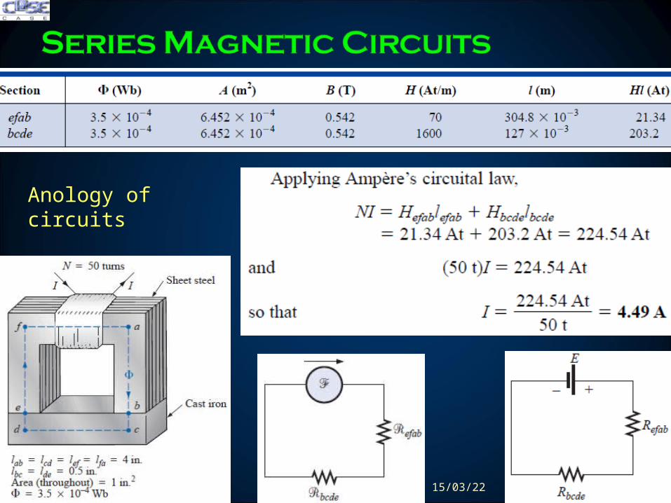
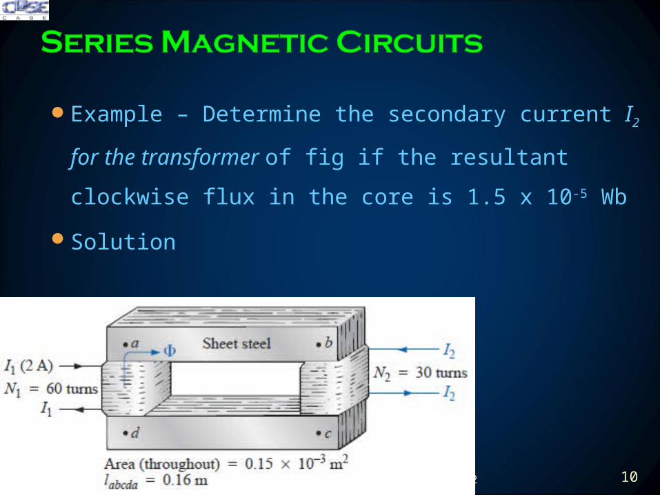
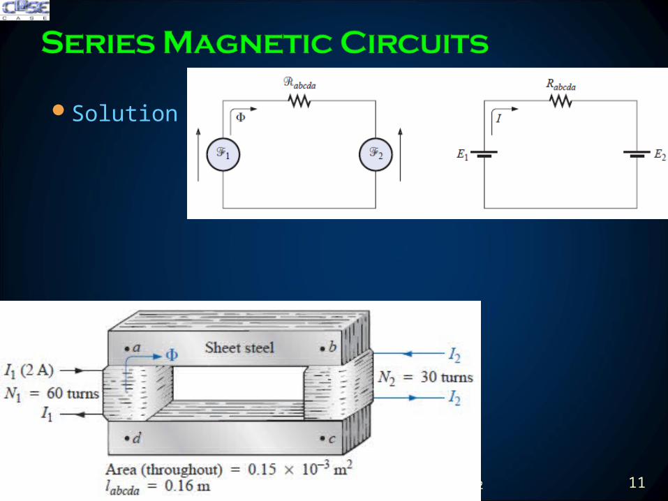
Solution
200423 11
Solution
200423 12
Solution
200423 13
The spreading of the flux lines outside the common area of
the core for the air gap in fig (a) is known as fringing
Neglect this effect of fringing as shown in fig (b)
The flux density of air gap is given by
Where
200423 14
For most practical applications the permeability of air is
taken to be equal to that of free space The magnetizing
force of the air gap is then determined by
and the mmf drop across the air gap is equal to Hglg An
equation for Hg is as follows
200423 15
Example ndash Find the value of I required to establish a
magnetic flux of φ = 075 x 10-4 Wb in the series magnetic
circuit of fig
Solution
200423 16
Example ndash Find the value of I φ = 075 x 10-4 Wb
Solution
200423 17
Example ndash Determine the current I required to establish a
flux of φ =15 x 10-4 Wb in the section of the core indicated
in fig
Solution
200423 18
Here NI is given and the flux φ must be found
This is a relatively straightforward problem if only one
magnetic section is involved Then
For magnetic circuits with more than one section there is
no set order of steps that will lead to an exact solution for
every problem on the first attempt
200423 19
We must find the impressed mmf for a calculated guess of
flux φ and then compare this with specified value of mmf
For most applications a value within plusmn5 of the actual Φ
or specified NI is acceptable
We can make a reasonable guess at the value of Φ if we
realize that the maximum mmf drop appears across the
material with the smallest permeability if the length and
area of each material are the same
200423 20
Example ndash Calculate the magnetic flux Φ for the magnetic
circuit of fig
Solution
200423 21
Example ndash Find the magnetic flux Φ for the series
magnetic circuit of fig for the specified impressed mmf
Solution
200423 22
Example ndash Find the magnetic flux Φ
Solution
200423 23
Example ndash Find the magnetic flux Φ
Solution
200423 24
Example ndash Find the magnetic flux Φ
Solution
200423 25
Recording System
The basic recording process is same as in computer hard
disks
0003 m2
A
1048576
200423 26
Speakers and Microphones
Electromagnetic effects used as moving force in speaker design
As the current peaks and returns to the valleys of the sound
pattern the strength of the electromagnet varies in exactly the
same manner This causes the cone of the speaker to vibrate at a
frequency directly proportional to the pulsating input
200423 27
Speakers and Microphones
A second design used more frequently in more expensive speaker
system using permanent magnet High peaking currents at the input
produce a strong flux pattern in the voice coil causing it to be drawn
well into flux pattern of permanent magnet
200423 28
Speakers and Microphones
Dynamic microphones such as above also employ
electromagnetic effects The sound to be reproduced at a higher
audio level causes the core and attached moving coil to move
within the magnetic field of the permanent magnet
Through Faradayrsquos law (e = N dΦdt) a voltage is induced
across the movable coil proportional to the speed with which it is
moving through the magnetic field The resulting induced
voltage pattern can then be amplified and reproduced at a much
higher audio level through the use of speakers
200423 29
Computer Hard Disks
The computer hard disk stores data on a magnetic coating applied to the
surface of circular platters that spin like a record The platters are
constructed on a base of aluminium or glass (both nonferromagnetic)
which makes them rigidmdashhence the term hard disk
The magnetic coating on the platters is called the media and is of either
the oxide or the thin-film variety
200423 30
Computer Hard Disks
The information on a disk is stored around the disk in circular paths called
tracks or cylinders
In its simplest form the writeread head of a hard disk (or floppy disk) is a
U-shaped electromagnet with an air gap that rides just above the surface
of the disk
200423 31
Computer Hard Disks
As the disk rotates information in the form of a voltage with changing
polarities is applied to the winding of the electromagnet
If we energize a positive voltage level with a 1 level (of binary arithmetic)
and a negative voltage level with a 0 level the resulting magnetic flux
pattern will have the direction shown in the core
200423 32
Computer Hard Disks
When the flux pattern encounters the air gap of the core it jumps to the
magnetic material (since magnetic flux always seeks the path of least
reluctance and air has a high reluctance) and establishes a flux pattern
as shown on the disk until it reaches the other end of the core air gap
where it returns to the electromagnet and completes the path
200423 33
Computer Hard Disks
As the head moves to the next bit sector it leaves behind the
magnetic flux pattern just established from the left to the right
200423 34
Computer Hard Disks
Data reading is done by a significant change in flux occurs when the
head passes over the transition region causing a measurable voltage to
be generated across the terminals of the pickup coil as dictated by
Faradayrsquos law
200423 35
Hall Effect Sensors
The Hall effect sensor is a semiconductor device that generates an
output voltage when exposed to a magnetic field
If a magnetic field is applied as perpendicular to the direction of the
current a voltage VH will be generated between the two terminals
200423 36
Hall Effect Sensors
The force causes the electrons to accumulate in the bottom region of
the semiconductor (connected to the negative terminal of the voltage
VH) leaving a net positive charge in the upper region of the material
(connected to the positive terminal of VH)
The stronger the current or strength of the magnetic field the greater
the induced voltage VH
200423 37
Hall Effect Sensors
The most widespread use of hall effect is as a trigger for an alarm
system in large department stores where theft is often a difficult
problem
A magnetic strip attached to the merchandise sounds an alarm when a
customer passes through the exit gates without paying for the product
The sensor control current and monitoring system are housed in the
exit fence and react to the presence of the magnetic field as the product
leaves the store
When the product is paid for the cashier removes the strip or
demagnetizes the strip by applying a magnetizing force that reduces the
residual magnetism in the strip to essentially zero200423 38
Magnetic Reed Switch
200423 39
Magnetic Resonance Image (MRI or NMR vs CAT Scans)
The three major components of an MRI system are a huge
magnet that can weigh up to 100 tons a table for transporting
the patient into the circular hole in the magnet and a control
200423 40
Magnetic Resonance Image (MRI or NMR vs CAT Scans)
A strong magnetic field that causes the nuclei of certain atoms in the
body to line up
Radio waves of different frequencies are then applied to the patient in
the region of interest and if the frequency of the wave matches the
natural frequency of the atom the nuclei will be set into a state of
resonance and will absorb energy from the applied signal
200423 41
Magnetic Resonance Image (MRI or NMR vs CAT Scans)
When the signal is removed the nuclei release the acquired energy in
the form of weak but detectable signals The strength and duration of
the energy emission vary from one tissue of the body to another The
weak signals are then amplified digitized and translated to provide a
cross-sectional image
200423 42
Review
Amperersquos Circuital Law ndash (Applying KVL)
The Flux Φ ndash (Applying KCL)
Series Magnetic Circuits
Air Gaps
Series-Parallel Magnetic Circuits
Determining Flux Φ
Applications
200423 44
200423 45
200423 46
- TODAYrsquoS LECTURE CONTENTS
- Amperersquos Circuital Law ndash (KVL)
- The Flux Φ ndash (KCL)
- Series Magnetic Circuits
- Series Magnetic Circuits
- Slide 7
- Slide 8
- Slide 9
- Slide 10
- Slide 11
- Slide 12
- Slide 13
- Air Gaps
- Slide 15
- Air gaps
- Slide 17
- Series ndash Parallel Magnetic Circuits
- Determining flux φ
- Slide 20
- Slide 21
- Slide 22
- Slide 23
- Slide 24
- Slide 25
- Applications ndash Magnetic Circuits
- Slide 27
- Slide 28
- Slide 29
- Slide 30
- Slide 31
- Slide 32
- Slide 33
- Slide 34
- Slide 35
- Slide 36
- Slide 37
- Slide 38
- Slide 39
- Slide 40
- Slide 41
- Slide 42
- Summary Conclusion
- Slide 44
- Hysteresis
- Slide 46
-
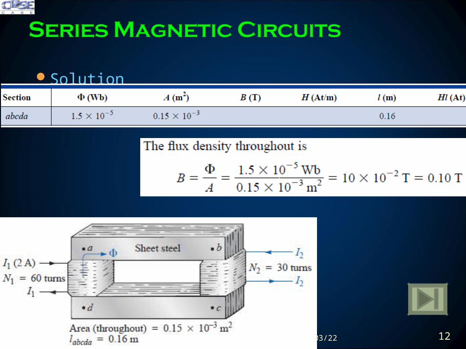
Solution
200423 12
Solution
200423 13
The spreading of the flux lines outside the common area of
the core for the air gap in fig (a) is known as fringing
Neglect this effect of fringing as shown in fig (b)
The flux density of air gap is given by
Where
200423 14
For most practical applications the permeability of air is
taken to be equal to that of free space The magnetizing
force of the air gap is then determined by
and the mmf drop across the air gap is equal to Hglg An
equation for Hg is as follows
200423 15
Example ndash Find the value of I required to establish a
magnetic flux of φ = 075 x 10-4 Wb in the series magnetic
circuit of fig
Solution
200423 16
Example ndash Find the value of I φ = 075 x 10-4 Wb
Solution
200423 17
Example ndash Determine the current I required to establish a
flux of φ =15 x 10-4 Wb in the section of the core indicated
in fig
Solution
200423 18
Here NI is given and the flux φ must be found
This is a relatively straightforward problem if only one
magnetic section is involved Then
For magnetic circuits with more than one section there is
no set order of steps that will lead to an exact solution for
every problem on the first attempt
200423 19
We must find the impressed mmf for a calculated guess of
flux φ and then compare this with specified value of mmf
For most applications a value within plusmn5 of the actual Φ
or specified NI is acceptable
We can make a reasonable guess at the value of Φ if we
realize that the maximum mmf drop appears across the
material with the smallest permeability if the length and
area of each material are the same
200423 20
Example ndash Calculate the magnetic flux Φ for the magnetic
circuit of fig
Solution
200423 21
Example ndash Find the magnetic flux Φ for the series
magnetic circuit of fig for the specified impressed mmf
Solution
200423 22
Example ndash Find the magnetic flux Φ
Solution
200423 23
Example ndash Find the magnetic flux Φ
Solution
200423 24
Example ndash Find the magnetic flux Φ
Solution
200423 25
Recording System
The basic recording process is same as in computer hard
disks
0003 m2
A
1048576
200423 26
Speakers and Microphones
Electromagnetic effects used as moving force in speaker design
As the current peaks and returns to the valleys of the sound
pattern the strength of the electromagnet varies in exactly the
same manner This causes the cone of the speaker to vibrate at a
frequency directly proportional to the pulsating input
200423 27
Speakers and Microphones
A second design used more frequently in more expensive speaker
system using permanent magnet High peaking currents at the input
produce a strong flux pattern in the voice coil causing it to be drawn
well into flux pattern of permanent magnet
200423 28
Speakers and Microphones
Dynamic microphones such as above also employ
electromagnetic effects The sound to be reproduced at a higher
audio level causes the core and attached moving coil to move
within the magnetic field of the permanent magnet
Through Faradayrsquos law (e = N dΦdt) a voltage is induced
across the movable coil proportional to the speed with which it is
moving through the magnetic field The resulting induced
voltage pattern can then be amplified and reproduced at a much
higher audio level through the use of speakers
200423 29
Computer Hard Disks
The computer hard disk stores data on a magnetic coating applied to the
surface of circular platters that spin like a record The platters are
constructed on a base of aluminium or glass (both nonferromagnetic)
which makes them rigidmdashhence the term hard disk
The magnetic coating on the platters is called the media and is of either
the oxide or the thin-film variety
200423 30
Computer Hard Disks
The information on a disk is stored around the disk in circular paths called
tracks or cylinders
In its simplest form the writeread head of a hard disk (or floppy disk) is a
U-shaped electromagnet with an air gap that rides just above the surface
of the disk
200423 31
Computer Hard Disks
As the disk rotates information in the form of a voltage with changing
polarities is applied to the winding of the electromagnet
If we energize a positive voltage level with a 1 level (of binary arithmetic)
and a negative voltage level with a 0 level the resulting magnetic flux
pattern will have the direction shown in the core
200423 32
Computer Hard Disks
When the flux pattern encounters the air gap of the core it jumps to the
magnetic material (since magnetic flux always seeks the path of least
reluctance and air has a high reluctance) and establishes a flux pattern
as shown on the disk until it reaches the other end of the core air gap
where it returns to the electromagnet and completes the path
200423 33
Computer Hard Disks
As the head moves to the next bit sector it leaves behind the
magnetic flux pattern just established from the left to the right
200423 34
Computer Hard Disks
Data reading is done by a significant change in flux occurs when the
head passes over the transition region causing a measurable voltage to
be generated across the terminals of the pickup coil as dictated by
Faradayrsquos law
200423 35
Hall Effect Sensors
The Hall effect sensor is a semiconductor device that generates an
output voltage when exposed to a magnetic field
If a magnetic field is applied as perpendicular to the direction of the
current a voltage VH will be generated between the two terminals
200423 36
Hall Effect Sensors
The force causes the electrons to accumulate in the bottom region of
the semiconductor (connected to the negative terminal of the voltage
VH) leaving a net positive charge in the upper region of the material
(connected to the positive terminal of VH)
The stronger the current or strength of the magnetic field the greater
the induced voltage VH
200423 37
Hall Effect Sensors
The most widespread use of hall effect is as a trigger for an alarm
system in large department stores where theft is often a difficult
problem
A magnetic strip attached to the merchandise sounds an alarm when a
customer passes through the exit gates without paying for the product
The sensor control current and monitoring system are housed in the
exit fence and react to the presence of the magnetic field as the product
leaves the store
When the product is paid for the cashier removes the strip or
demagnetizes the strip by applying a magnetizing force that reduces the
residual magnetism in the strip to essentially zero200423 38
Magnetic Reed Switch
200423 39
Magnetic Resonance Image (MRI or NMR vs CAT Scans)
The three major components of an MRI system are a huge
magnet that can weigh up to 100 tons a table for transporting
the patient into the circular hole in the magnet and a control
200423 40
Magnetic Resonance Image (MRI or NMR vs CAT Scans)
A strong magnetic field that causes the nuclei of certain atoms in the
body to line up
Radio waves of different frequencies are then applied to the patient in
the region of interest and if the frequency of the wave matches the
natural frequency of the atom the nuclei will be set into a state of
resonance and will absorb energy from the applied signal
200423 41
Magnetic Resonance Image (MRI or NMR vs CAT Scans)
When the signal is removed the nuclei release the acquired energy in
the form of weak but detectable signals The strength and duration of
the energy emission vary from one tissue of the body to another The
weak signals are then amplified digitized and translated to provide a
cross-sectional image
200423 42
Review
Amperersquos Circuital Law ndash (Applying KVL)
The Flux Φ ndash (Applying KCL)
Series Magnetic Circuits
Air Gaps
Series-Parallel Magnetic Circuits
Determining Flux Φ
Applications
200423 44
200423 45
200423 46
- TODAYrsquoS LECTURE CONTENTS
- Amperersquos Circuital Law ndash (KVL)
- The Flux Φ ndash (KCL)
- Series Magnetic Circuits
- Series Magnetic Circuits
- Slide 7
- Slide 8
- Slide 9
- Slide 10
- Slide 11
- Slide 12
- Slide 13
- Air Gaps
- Slide 15
- Air gaps
- Slide 17
- Series ndash Parallel Magnetic Circuits
- Determining flux φ
- Slide 20
- Slide 21
- Slide 22
- Slide 23
- Slide 24
- Slide 25
- Applications ndash Magnetic Circuits
- Slide 27
- Slide 28
- Slide 29
- Slide 30
- Slide 31
- Slide 32
- Slide 33
- Slide 34
- Slide 35
- Slide 36
- Slide 37
- Slide 38
- Slide 39
- Slide 40
- Slide 41
- Slide 42
- Summary Conclusion
- Slide 44
- Hysteresis
- Slide 46
-
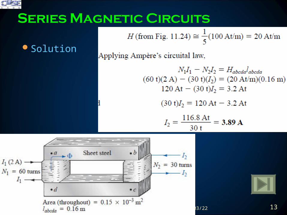
Solution
200423 13
The spreading of the flux lines outside the common area of
the core for the air gap in fig (a) is known as fringing
Neglect this effect of fringing as shown in fig (b)
The flux density of air gap is given by
Where
200423 14
For most practical applications the permeability of air is
taken to be equal to that of free space The magnetizing
force of the air gap is then determined by
and the mmf drop across the air gap is equal to Hglg An
equation for Hg is as follows
200423 15
Example ndash Find the value of I required to establish a
magnetic flux of φ = 075 x 10-4 Wb in the series magnetic
circuit of fig
Solution
200423 16
Example ndash Find the value of I φ = 075 x 10-4 Wb
Solution
200423 17
Example ndash Determine the current I required to establish a
flux of φ =15 x 10-4 Wb in the section of the core indicated
in fig
Solution
200423 18
Here NI is given and the flux φ must be found
This is a relatively straightforward problem if only one
magnetic section is involved Then
For magnetic circuits with more than one section there is
no set order of steps that will lead to an exact solution for
every problem on the first attempt
200423 19
We must find the impressed mmf for a calculated guess of
flux φ and then compare this with specified value of mmf
For most applications a value within plusmn5 of the actual Φ
or specified NI is acceptable
We can make a reasonable guess at the value of Φ if we
realize that the maximum mmf drop appears across the
material with the smallest permeability if the length and
area of each material are the same
200423 20
Example ndash Calculate the magnetic flux Φ for the magnetic
circuit of fig
Solution
200423 21
Example ndash Find the magnetic flux Φ for the series
magnetic circuit of fig for the specified impressed mmf
Solution
200423 22
Example ndash Find the magnetic flux Φ
Solution
200423 23
Example ndash Find the magnetic flux Φ
Solution
200423 24
Example ndash Find the magnetic flux Φ
Solution
200423 25
Recording System
The basic recording process is same as in computer hard
disks
0003 m2
A
1048576
200423 26
Speakers and Microphones
Electromagnetic effects used as moving force in speaker design
As the current peaks and returns to the valleys of the sound
pattern the strength of the electromagnet varies in exactly the
same manner This causes the cone of the speaker to vibrate at a
frequency directly proportional to the pulsating input
200423 27
Speakers and Microphones
A second design used more frequently in more expensive speaker
system using permanent magnet High peaking currents at the input
produce a strong flux pattern in the voice coil causing it to be drawn
well into flux pattern of permanent magnet
200423 28
Speakers and Microphones
Dynamic microphones such as above also employ
electromagnetic effects The sound to be reproduced at a higher
audio level causes the core and attached moving coil to move
within the magnetic field of the permanent magnet
Through Faradayrsquos law (e = N dΦdt) a voltage is induced
across the movable coil proportional to the speed with which it is
moving through the magnetic field The resulting induced
voltage pattern can then be amplified and reproduced at a much
higher audio level through the use of speakers
200423 29
Computer Hard Disks
The computer hard disk stores data on a magnetic coating applied to the
surface of circular platters that spin like a record The platters are
constructed on a base of aluminium or glass (both nonferromagnetic)
which makes them rigidmdashhence the term hard disk
The magnetic coating on the platters is called the media and is of either
the oxide or the thin-film variety
200423 30
Computer Hard Disks
The information on a disk is stored around the disk in circular paths called
tracks or cylinders
In its simplest form the writeread head of a hard disk (or floppy disk) is a
U-shaped electromagnet with an air gap that rides just above the surface
of the disk
200423 31
Computer Hard Disks
As the disk rotates information in the form of a voltage with changing
polarities is applied to the winding of the electromagnet
If we energize a positive voltage level with a 1 level (of binary arithmetic)
and a negative voltage level with a 0 level the resulting magnetic flux
pattern will have the direction shown in the core
200423 32
Computer Hard Disks
When the flux pattern encounters the air gap of the core it jumps to the
magnetic material (since magnetic flux always seeks the path of least
reluctance and air has a high reluctance) and establishes a flux pattern
as shown on the disk until it reaches the other end of the core air gap
where it returns to the electromagnet and completes the path
200423 33
Computer Hard Disks
As the head moves to the next bit sector it leaves behind the
magnetic flux pattern just established from the left to the right
200423 34
Computer Hard Disks
Data reading is done by a significant change in flux occurs when the
head passes over the transition region causing a measurable voltage to
be generated across the terminals of the pickup coil as dictated by
Faradayrsquos law
200423 35
Hall Effect Sensors
The Hall effect sensor is a semiconductor device that generates an
output voltage when exposed to a magnetic field
If a magnetic field is applied as perpendicular to the direction of the
current a voltage VH will be generated between the two terminals
200423 36
Hall Effect Sensors
The force causes the electrons to accumulate in the bottom region of
the semiconductor (connected to the negative terminal of the voltage
VH) leaving a net positive charge in the upper region of the material
(connected to the positive terminal of VH)
The stronger the current or strength of the magnetic field the greater
the induced voltage VH
200423 37
Hall Effect Sensors
The most widespread use of hall effect is as a trigger for an alarm
system in large department stores where theft is often a difficult
problem
A magnetic strip attached to the merchandise sounds an alarm when a
customer passes through the exit gates without paying for the product
The sensor control current and monitoring system are housed in the
exit fence and react to the presence of the magnetic field as the product
leaves the store
When the product is paid for the cashier removes the strip or
demagnetizes the strip by applying a magnetizing force that reduces the
residual magnetism in the strip to essentially zero200423 38
Magnetic Reed Switch
200423 39
Magnetic Resonance Image (MRI or NMR vs CAT Scans)
The three major components of an MRI system are a huge
magnet that can weigh up to 100 tons a table for transporting
the patient into the circular hole in the magnet and a control
200423 40
Magnetic Resonance Image (MRI or NMR vs CAT Scans)
A strong magnetic field that causes the nuclei of certain atoms in the
body to line up
Radio waves of different frequencies are then applied to the patient in
the region of interest and if the frequency of the wave matches the
natural frequency of the atom the nuclei will be set into a state of
resonance and will absorb energy from the applied signal
200423 41
Magnetic Resonance Image (MRI or NMR vs CAT Scans)
When the signal is removed the nuclei release the acquired energy in
the form of weak but detectable signals The strength and duration of
the energy emission vary from one tissue of the body to another The
weak signals are then amplified digitized and translated to provide a
cross-sectional image
200423 42
Review
Amperersquos Circuital Law ndash (Applying KVL)
The Flux Φ ndash (Applying KCL)
Series Magnetic Circuits
Air Gaps
Series-Parallel Magnetic Circuits
Determining Flux Φ
Applications
200423 44
200423 45
200423 46
- TODAYrsquoS LECTURE CONTENTS
- Amperersquos Circuital Law ndash (KVL)
- The Flux Φ ndash (KCL)
- Series Magnetic Circuits
- Series Magnetic Circuits
- Slide 7
- Slide 8
- Slide 9
- Slide 10
- Slide 11
- Slide 12
- Slide 13
- Air Gaps
- Slide 15
- Air gaps
- Slide 17
- Series ndash Parallel Magnetic Circuits
- Determining flux φ
- Slide 20
- Slide 21
- Slide 22
- Slide 23
- Slide 24
- Slide 25
- Applications ndash Magnetic Circuits
- Slide 27
- Slide 28
- Slide 29
- Slide 30
- Slide 31
- Slide 32
- Slide 33
- Slide 34
- Slide 35
- Slide 36
- Slide 37
- Slide 38
- Slide 39
- Slide 40
- Slide 41
- Slide 42
- Summary Conclusion
- Slide 44
- Hysteresis
- Slide 46
-
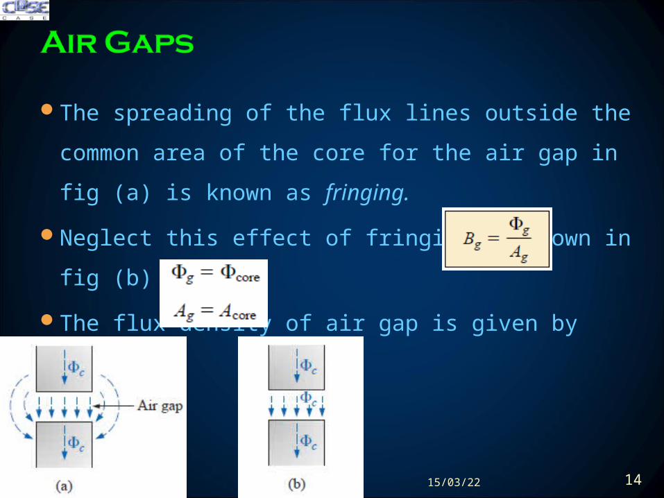
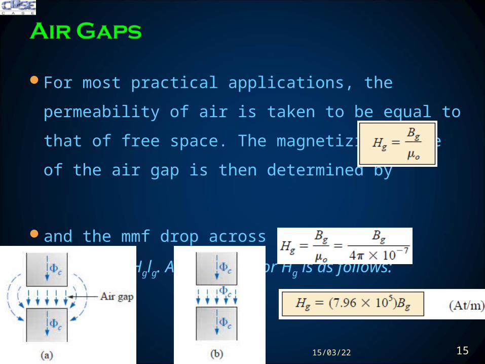
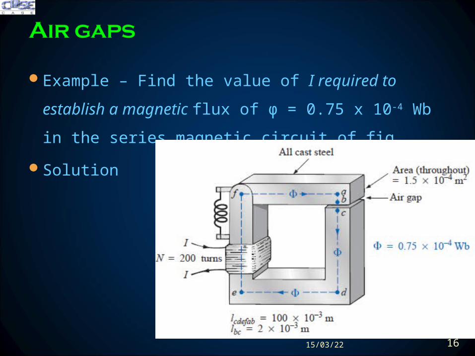
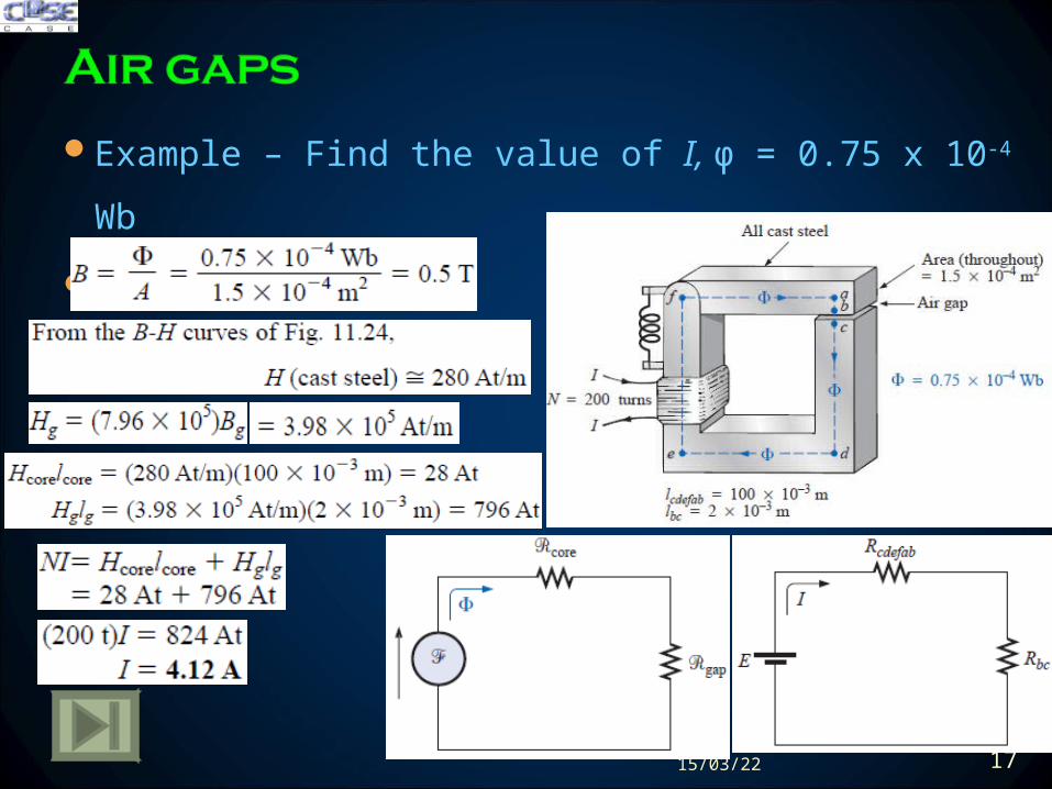
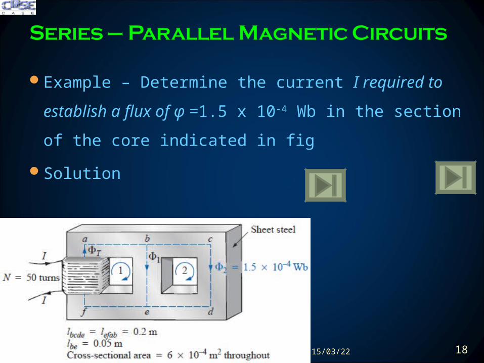
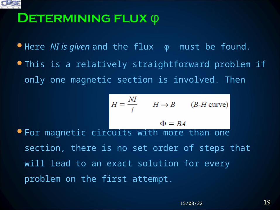
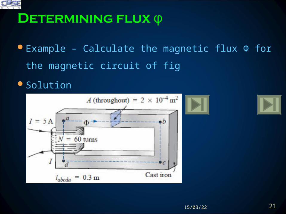
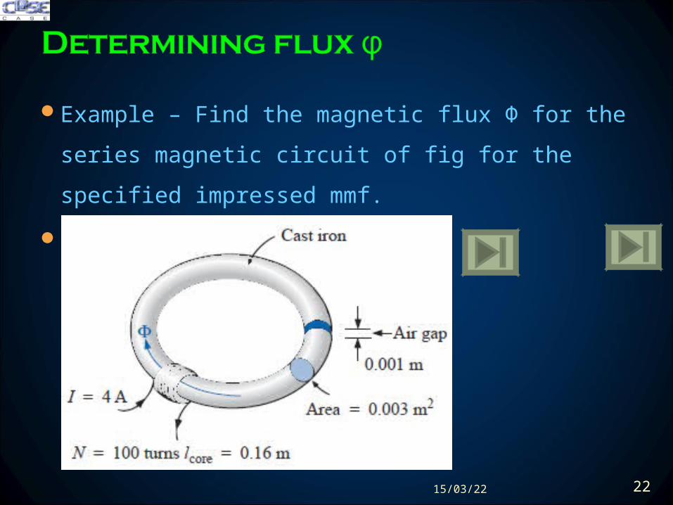

Example ndash Find the magnetic flux Φ
Solution
200423 24
Example ndash Find the magnetic flux Φ
Solution
200423 25
Recording System
The basic recording process is same as in computer hard
disks
0003 m2
A
1048576
200423 26
Speakers and Microphones
Electromagnetic effects used as moving force in speaker design
As the current peaks and returns to the valleys of the sound
pattern the strength of the electromagnet varies in exactly the
same manner This causes the cone of the speaker to vibrate at a
frequency directly proportional to the pulsating input
200423 27
Speakers and Microphones
A second design used more frequently in more expensive speaker
system using permanent magnet High peaking currents at the input
produce a strong flux pattern in the voice coil causing it to be drawn
well into flux pattern of permanent magnet
200423 28
Speakers and Microphones
Dynamic microphones such as above also employ
electromagnetic effects The sound to be reproduced at a higher
audio level causes the core and attached moving coil to move
within the magnetic field of the permanent magnet
Through Faradayrsquos law (e = N dΦdt) a voltage is induced
across the movable coil proportional to the speed with which it is
moving through the magnetic field The resulting induced
voltage pattern can then be amplified and reproduced at a much
higher audio level through the use of speakers
200423 29
Computer Hard Disks
The computer hard disk stores data on a magnetic coating applied to the
surface of circular platters that spin like a record The platters are
constructed on a base of aluminium or glass (both nonferromagnetic)
which makes them rigidmdashhence the term hard disk
The magnetic coating on the platters is called the media and is of either
the oxide or the thin-film variety
200423 30
Computer Hard Disks
The information on a disk is stored around the disk in circular paths called
tracks or cylinders
In its simplest form the writeread head of a hard disk (or floppy disk) is a
U-shaped electromagnet with an air gap that rides just above the surface
of the disk
200423 31
Computer Hard Disks
As the disk rotates information in the form of a voltage with changing
polarities is applied to the winding of the electromagnet
If we energize a positive voltage level with a 1 level (of binary arithmetic)
and a negative voltage level with a 0 level the resulting magnetic flux
pattern will have the direction shown in the core
200423 32
Computer Hard Disks
When the flux pattern encounters the air gap of the core it jumps to the
magnetic material (since magnetic flux always seeks the path of least
reluctance and air has a high reluctance) and establishes a flux pattern
as shown on the disk until it reaches the other end of the core air gap
where it returns to the electromagnet and completes the path
200423 33
Computer Hard Disks
As the head moves to the next bit sector it leaves behind the
magnetic flux pattern just established from the left to the right
200423 34
Computer Hard Disks
Data reading is done by a significant change in flux occurs when the
head passes over the transition region causing a measurable voltage to
be generated across the terminals of the pickup coil as dictated by
Faradayrsquos law
200423 35
Hall Effect Sensors
The Hall effect sensor is a semiconductor device that generates an
output voltage when exposed to a magnetic field
If a magnetic field is applied as perpendicular to the direction of the
current a voltage VH will be generated between the two terminals
200423 36
Hall Effect Sensors
The force causes the electrons to accumulate in the bottom region of
the semiconductor (connected to the negative terminal of the voltage
VH) leaving a net positive charge in the upper region of the material
(connected to the positive terminal of VH)
The stronger the current or strength of the magnetic field the greater
the induced voltage VH
200423 37
Hall Effect Sensors
The most widespread use of hall effect is as a trigger for an alarm
system in large department stores where theft is often a difficult
problem
A magnetic strip attached to the merchandise sounds an alarm when a
customer passes through the exit gates without paying for the product
The sensor control current and monitoring system are housed in the
exit fence and react to the presence of the magnetic field as the product
leaves the store
When the product is paid for the cashier removes the strip or
demagnetizes the strip by applying a magnetizing force that reduces the
residual magnetism in the strip to essentially zero200423 38
Magnetic Reed Switch
200423 39
Magnetic Resonance Image (MRI or NMR vs CAT Scans)
The three major components of an MRI system are a huge
magnet that can weigh up to 100 tons a table for transporting
the patient into the circular hole in the magnet and a control
200423 40
Magnetic Resonance Image (MRI or NMR vs CAT Scans)
A strong magnetic field that causes the nuclei of certain atoms in the
body to line up
Radio waves of different frequencies are then applied to the patient in
the region of interest and if the frequency of the wave matches the
natural frequency of the atom the nuclei will be set into a state of
resonance and will absorb energy from the applied signal
200423 41
Magnetic Resonance Image (MRI or NMR vs CAT Scans)
When the signal is removed the nuclei release the acquired energy in
the form of weak but detectable signals The strength and duration of
the energy emission vary from one tissue of the body to another The
weak signals are then amplified digitized and translated to provide a
cross-sectional image
200423 42
Review
Amperersquos Circuital Law ndash (Applying KVL)
The Flux Φ ndash (Applying KCL)
Series Magnetic Circuits
Air Gaps
Series-Parallel Magnetic Circuits
Determining Flux Φ
Applications
200423 44
200423 45
200423 46
- TODAYrsquoS LECTURE CONTENTS
- Amperersquos Circuital Law ndash (KVL)
- The Flux Φ ndash (KCL)
- Series Magnetic Circuits
- Series Magnetic Circuits
- Slide 7
- Slide 8
- Slide 9
- Slide 10
- Slide 11
- Slide 12
- Slide 13
- Air Gaps
- Slide 15
- Air gaps
- Slide 17
- Series ndash Parallel Magnetic Circuits
- Determining flux φ
- Slide 20
- Slide 21
- Slide 22
- Slide 23
- Slide 24
- Slide 25
- Applications ndash Magnetic Circuits
- Slide 27
- Slide 28
- Slide 29
- Slide 30
- Slide 31
- Slide 32
- Slide 33
- Slide 34
- Slide 35
- Slide 36
- Slide 37
- Slide 38
- Slide 39
- Slide 40
- Slide 41
- Slide 42
- Summary Conclusion
- Slide 44
- Hysteresis
- Slide 46
-
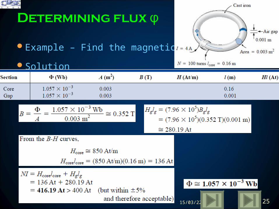
Example ndash Find the magnetic flux Φ
Solution
200423 25
Recording System
The basic recording process is same as in computer hard
disks
0003 m2
A
1048576
200423 26
Speakers and Microphones
Electromagnetic effects used as moving force in speaker design
As the current peaks and returns to the valleys of the sound
pattern the strength of the electromagnet varies in exactly the
same manner This causes the cone of the speaker to vibrate at a
frequency directly proportional to the pulsating input
200423 27
Speakers and Microphones
A second design used more frequently in more expensive speaker
system using permanent magnet High peaking currents at the input
produce a strong flux pattern in the voice coil causing it to be drawn
well into flux pattern of permanent magnet
200423 28
Speakers and Microphones
Dynamic microphones such as above also employ
electromagnetic effects The sound to be reproduced at a higher
audio level causes the core and attached moving coil to move
within the magnetic field of the permanent magnet
Through Faradayrsquos law (e = N dΦdt) a voltage is induced
across the movable coil proportional to the speed with which it is
moving through the magnetic field The resulting induced
voltage pattern can then be amplified and reproduced at a much
higher audio level through the use of speakers
200423 29
Computer Hard Disks
The computer hard disk stores data on a magnetic coating applied to the
surface of circular platters that spin like a record The platters are
constructed on a base of aluminium or glass (both nonferromagnetic)
which makes them rigidmdashhence the term hard disk
The magnetic coating on the platters is called the media and is of either
the oxide or the thin-film variety
200423 30
Computer Hard Disks
The information on a disk is stored around the disk in circular paths called
tracks or cylinders
In its simplest form the writeread head of a hard disk (or floppy disk) is a
U-shaped electromagnet with an air gap that rides just above the surface
of the disk
200423 31
Computer Hard Disks
As the disk rotates information in the form of a voltage with changing
polarities is applied to the winding of the electromagnet
If we energize a positive voltage level with a 1 level (of binary arithmetic)
and a negative voltage level with a 0 level the resulting magnetic flux
pattern will have the direction shown in the core
200423 32
Computer Hard Disks
When the flux pattern encounters the air gap of the core it jumps to the
magnetic material (since magnetic flux always seeks the path of least
reluctance and air has a high reluctance) and establishes a flux pattern
as shown on the disk until it reaches the other end of the core air gap
where it returns to the electromagnet and completes the path
200423 33
Computer Hard Disks
As the head moves to the next bit sector it leaves behind the
magnetic flux pattern just established from the left to the right
200423 34
Computer Hard Disks
Data reading is done by a significant change in flux occurs when the
head passes over the transition region causing a measurable voltage to
be generated across the terminals of the pickup coil as dictated by
Faradayrsquos law
200423 35
Hall Effect Sensors
The Hall effect sensor is a semiconductor device that generates an
output voltage when exposed to a magnetic field
If a magnetic field is applied as perpendicular to the direction of the
current a voltage VH will be generated between the two terminals
200423 36
Hall Effect Sensors
The force causes the electrons to accumulate in the bottom region of
the semiconductor (connected to the negative terminal of the voltage
VH) leaving a net positive charge in the upper region of the material
(connected to the positive terminal of VH)
The stronger the current or strength of the magnetic field the greater
the induced voltage VH
200423 37
Hall Effect Sensors
The most widespread use of hall effect is as a trigger for an alarm
system in large department stores where theft is often a difficult
problem
A magnetic strip attached to the merchandise sounds an alarm when a
customer passes through the exit gates without paying for the product
The sensor control current and monitoring system are housed in the
exit fence and react to the presence of the magnetic field as the product
leaves the store
When the product is paid for the cashier removes the strip or
demagnetizes the strip by applying a magnetizing force that reduces the
residual magnetism in the strip to essentially zero200423 38
Magnetic Reed Switch
200423 39
Magnetic Resonance Image (MRI or NMR vs CAT Scans)
The three major components of an MRI system are a huge
magnet that can weigh up to 100 tons a table for transporting
the patient into the circular hole in the magnet and a control
200423 40
Magnetic Resonance Image (MRI or NMR vs CAT Scans)
A strong magnetic field that causes the nuclei of certain atoms in the
body to line up
Radio waves of different frequencies are then applied to the patient in
the region of interest and if the frequency of the wave matches the
natural frequency of the atom the nuclei will be set into a state of
resonance and will absorb energy from the applied signal
200423 41
Magnetic Resonance Image (MRI or NMR vs CAT Scans)
When the signal is removed the nuclei release the acquired energy in
the form of weak but detectable signals The strength and duration of
the energy emission vary from one tissue of the body to another The
weak signals are then amplified digitized and translated to provide a
cross-sectional image
200423 42
Review
Amperersquos Circuital Law ndash (Applying KVL)
The Flux Φ ndash (Applying KCL)
Series Magnetic Circuits
Air Gaps
Series-Parallel Magnetic Circuits
Determining Flux Φ
Applications
200423 44
200423 45
200423 46
- TODAYrsquoS LECTURE CONTENTS
- Amperersquos Circuital Law ndash (KVL)
- The Flux Φ ndash (KCL)
- Series Magnetic Circuits
- Series Magnetic Circuits
- Slide 7
- Slide 8
- Slide 9
- Slide 10
- Slide 11
- Slide 12
- Slide 13
- Air Gaps
- Slide 15
- Air gaps
- Slide 17
- Series ndash Parallel Magnetic Circuits
- Determining flux φ
- Slide 20
- Slide 21
- Slide 22
- Slide 23
- Slide 24
- Slide 25
- Applications ndash Magnetic Circuits
- Slide 27
- Slide 28
- Slide 29
- Slide 30
- Slide 31
- Slide 32
- Slide 33
- Slide 34
- Slide 35
- Slide 36
- Slide 37
- Slide 38
- Slide 39
- Slide 40
- Slide 41
- Slide 42
- Summary Conclusion
- Slide 44
- Hysteresis
- Slide 46
-
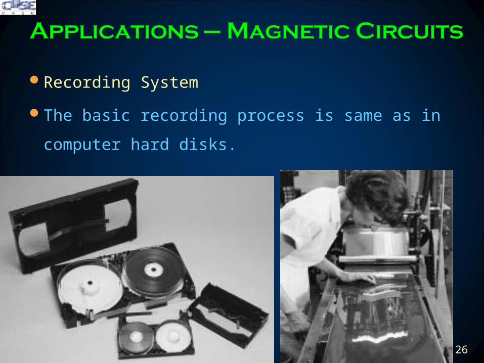
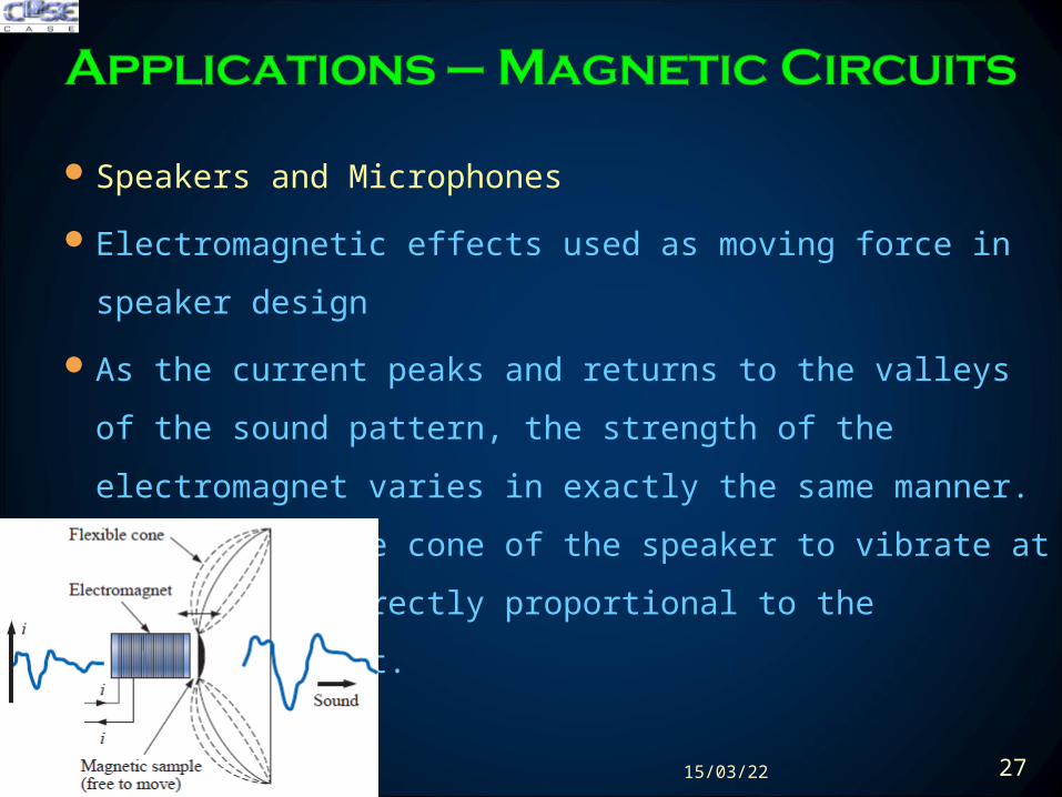
Speakers and Microphones
Electromagnetic effects used as moving force in speaker design
As the current peaks and returns to the valleys of the sound
pattern the strength of the electromagnet varies in exactly the
same manner This causes the cone of the speaker to vibrate at a
frequency directly proportional to the pulsating input
200423 27
Speakers and Microphones
A second design used more frequently in more expensive speaker
system using permanent magnet High peaking currents at the input
produce a strong flux pattern in the voice coil causing it to be drawn
well into flux pattern of permanent magnet
200423 28
Speakers and Microphones
Dynamic microphones such as above also employ
electromagnetic effects The sound to be reproduced at a higher
audio level causes the core and attached moving coil to move
within the magnetic field of the permanent magnet
Through Faradayrsquos law (e = N dΦdt) a voltage is induced
across the movable coil proportional to the speed with which it is
moving through the magnetic field The resulting induced
voltage pattern can then be amplified and reproduced at a much
higher audio level through the use of speakers
200423 29
Computer Hard Disks
The computer hard disk stores data on a magnetic coating applied to the
surface of circular platters that spin like a record The platters are
constructed on a base of aluminium or glass (both nonferromagnetic)
which makes them rigidmdashhence the term hard disk
The magnetic coating on the platters is called the media and is of either
the oxide or the thin-film variety
200423 30
Computer Hard Disks
The information on a disk is stored around the disk in circular paths called
tracks or cylinders
In its simplest form the writeread head of a hard disk (or floppy disk) is a
U-shaped electromagnet with an air gap that rides just above the surface
of the disk
200423 31
Computer Hard Disks
As the disk rotates information in the form of a voltage with changing
polarities is applied to the winding of the electromagnet
If we energize a positive voltage level with a 1 level (of binary arithmetic)
and a negative voltage level with a 0 level the resulting magnetic flux
pattern will have the direction shown in the core
200423 32
Computer Hard Disks
When the flux pattern encounters the air gap of the core it jumps to the
magnetic material (since magnetic flux always seeks the path of least
reluctance and air has a high reluctance) and establishes a flux pattern
as shown on the disk until it reaches the other end of the core air gap
where it returns to the electromagnet and completes the path
200423 33
Computer Hard Disks
As the head moves to the next bit sector it leaves behind the
magnetic flux pattern just established from the left to the right
200423 34
Computer Hard Disks
Data reading is done by a significant change in flux occurs when the
head passes over the transition region causing a measurable voltage to
be generated across the terminals of the pickup coil as dictated by
Faradayrsquos law
200423 35
Hall Effect Sensors
The Hall effect sensor is a semiconductor device that generates an
output voltage when exposed to a magnetic field
If a magnetic field is applied as perpendicular to the direction of the
current a voltage VH will be generated between the two terminals
200423 36
Hall Effect Sensors
The force causes the electrons to accumulate in the bottom region of
the semiconductor (connected to the negative terminal of the voltage
VH) leaving a net positive charge in the upper region of the material
(connected to the positive terminal of VH)
The stronger the current or strength of the magnetic field the greater
the induced voltage VH
200423 37
Hall Effect Sensors
The most widespread use of hall effect is as a trigger for an alarm
system in large department stores where theft is often a difficult
problem
A magnetic strip attached to the merchandise sounds an alarm when a
customer passes through the exit gates without paying for the product
The sensor control current and monitoring system are housed in the
exit fence and react to the presence of the magnetic field as the product
leaves the store
When the product is paid for the cashier removes the strip or
demagnetizes the strip by applying a magnetizing force that reduces the
residual magnetism in the strip to essentially zero200423 38
Magnetic Reed Switch
200423 39
Magnetic Resonance Image (MRI or NMR vs CAT Scans)
The three major components of an MRI system are a huge
magnet that can weigh up to 100 tons a table for transporting
the patient into the circular hole in the magnet and a control
200423 40
Magnetic Resonance Image (MRI or NMR vs CAT Scans)
A strong magnetic field that causes the nuclei of certain atoms in the
body to line up
Radio waves of different frequencies are then applied to the patient in
the region of interest and if the frequency of the wave matches the
natural frequency of the atom the nuclei will be set into a state of
resonance and will absorb energy from the applied signal
200423 41
Magnetic Resonance Image (MRI or NMR vs CAT Scans)
When the signal is removed the nuclei release the acquired energy in
the form of weak but detectable signals The strength and duration of
the energy emission vary from one tissue of the body to another The
weak signals are then amplified digitized and translated to provide a
cross-sectional image
200423 42
Review
Amperersquos Circuital Law ndash (Applying KVL)
The Flux Φ ndash (Applying KCL)
Series Magnetic Circuits
Air Gaps
Series-Parallel Magnetic Circuits
Determining Flux Φ
Applications
200423 44
200423 45
200423 46
- TODAYrsquoS LECTURE CONTENTS
- Amperersquos Circuital Law ndash (KVL)
- The Flux Φ ndash (KCL)
- Series Magnetic Circuits
- Series Magnetic Circuits
- Slide 7
- Slide 8
- Slide 9
- Slide 10
- Slide 11
- Slide 12
- Slide 13
- Air Gaps
- Slide 15
- Air gaps
- Slide 17
- Series ndash Parallel Magnetic Circuits
- Determining flux φ
- Slide 20
- Slide 21
- Slide 22
- Slide 23
- Slide 24
- Slide 25
- Applications ndash Magnetic Circuits
- Slide 27
- Slide 28
- Slide 29
- Slide 30
- Slide 31
- Slide 32
- Slide 33
- Slide 34
- Slide 35
- Slide 36
- Slide 37
- Slide 38
- Slide 39
- Slide 40
- Slide 41
- Slide 42
- Summary Conclusion
- Slide 44
- Hysteresis
- Slide 46
-
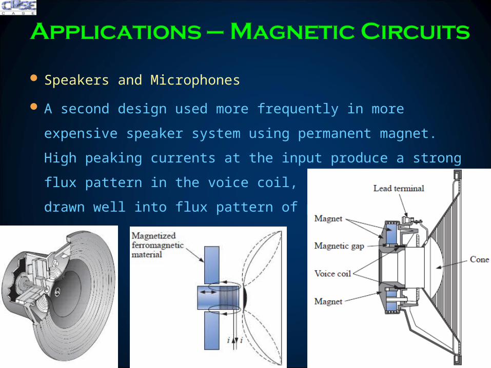
Speakers and Microphones
A second design used more frequently in more expensive speaker
system using permanent magnet High peaking currents at the input
produce a strong flux pattern in the voice coil causing it to be drawn
well into flux pattern of permanent magnet
200423 28
Speakers and Microphones
Dynamic microphones such as above also employ
electromagnetic effects The sound to be reproduced at a higher
audio level causes the core and attached moving coil to move
within the magnetic field of the permanent magnet
Through Faradayrsquos law (e = N dΦdt) a voltage is induced
across the movable coil proportional to the speed with which it is
moving through the magnetic field The resulting induced
voltage pattern can then be amplified and reproduced at a much
higher audio level through the use of speakers
200423 29
Computer Hard Disks
The computer hard disk stores data on a magnetic coating applied to the
surface of circular platters that spin like a record The platters are
constructed on a base of aluminium or glass (both nonferromagnetic)
which makes them rigidmdashhence the term hard disk
The magnetic coating on the platters is called the media and is of either
the oxide or the thin-film variety
200423 30
Computer Hard Disks
The information on a disk is stored around the disk in circular paths called
tracks or cylinders
In its simplest form the writeread head of a hard disk (or floppy disk) is a
U-shaped electromagnet with an air gap that rides just above the surface
of the disk
200423 31
Computer Hard Disks
As the disk rotates information in the form of a voltage with changing
polarities is applied to the winding of the electromagnet
If we energize a positive voltage level with a 1 level (of binary arithmetic)
and a negative voltage level with a 0 level the resulting magnetic flux
pattern will have the direction shown in the core
200423 32
Computer Hard Disks
When the flux pattern encounters the air gap of the core it jumps to the
magnetic material (since magnetic flux always seeks the path of least
reluctance and air has a high reluctance) and establishes a flux pattern
as shown on the disk until it reaches the other end of the core air gap
where it returns to the electromagnet and completes the path
200423 33
Computer Hard Disks
As the head moves to the next bit sector it leaves behind the
magnetic flux pattern just established from the left to the right
200423 34
Computer Hard Disks
Data reading is done by a significant change in flux occurs when the
head passes over the transition region causing a measurable voltage to
be generated across the terminals of the pickup coil as dictated by
Faradayrsquos law
200423 35
Hall Effect Sensors
The Hall effect sensor is a semiconductor device that generates an
output voltage when exposed to a magnetic field
If a magnetic field is applied as perpendicular to the direction of the
current a voltage VH will be generated between the two terminals
200423 36
Hall Effect Sensors
The force causes the electrons to accumulate in the bottom region of
the semiconductor (connected to the negative terminal of the voltage
VH) leaving a net positive charge in the upper region of the material
(connected to the positive terminal of VH)
The stronger the current or strength of the magnetic field the greater
the induced voltage VH
200423 37
Hall Effect Sensors
The most widespread use of hall effect is as a trigger for an alarm
system in large department stores where theft is often a difficult
problem
A magnetic strip attached to the merchandise sounds an alarm when a
customer passes through the exit gates without paying for the product
The sensor control current and monitoring system are housed in the
exit fence and react to the presence of the magnetic field as the product
leaves the store
When the product is paid for the cashier removes the strip or
demagnetizes the strip by applying a magnetizing force that reduces the
residual magnetism in the strip to essentially zero200423 38
Magnetic Reed Switch
200423 39
Magnetic Resonance Image (MRI or NMR vs CAT Scans)
The three major components of an MRI system are a huge
magnet that can weigh up to 100 tons a table for transporting
the patient into the circular hole in the magnet and a control
200423 40
Magnetic Resonance Image (MRI or NMR vs CAT Scans)
A strong magnetic field that causes the nuclei of certain atoms in the
body to line up
Radio waves of different frequencies are then applied to the patient in
the region of interest and if the frequency of the wave matches the
natural frequency of the atom the nuclei will be set into a state of
resonance and will absorb energy from the applied signal
200423 41
Magnetic Resonance Image (MRI or NMR vs CAT Scans)
When the signal is removed the nuclei release the acquired energy in
the form of weak but detectable signals The strength and duration of
the energy emission vary from one tissue of the body to another The
weak signals are then amplified digitized and translated to provide a
cross-sectional image
200423 42
Review
Amperersquos Circuital Law ndash (Applying KVL)
The Flux Φ ndash (Applying KCL)
Series Magnetic Circuits
Air Gaps
Series-Parallel Magnetic Circuits
Determining Flux Φ
Applications
200423 44
200423 45
200423 46
- TODAYrsquoS LECTURE CONTENTS
- Amperersquos Circuital Law ndash (KVL)
- The Flux Φ ndash (KCL)
- Series Magnetic Circuits
- Series Magnetic Circuits
- Slide 7
- Slide 8
- Slide 9
- Slide 10
- Slide 11
- Slide 12
- Slide 13
- Air Gaps
- Slide 15
- Air gaps
- Slide 17
- Series ndash Parallel Magnetic Circuits
- Determining flux φ
- Slide 20
- Slide 21
- Slide 22
- Slide 23
- Slide 24
- Slide 25
- Applications ndash Magnetic Circuits
- Slide 27
- Slide 28
- Slide 29
- Slide 30
- Slide 31
- Slide 32
- Slide 33
- Slide 34
- Slide 35
- Slide 36
- Slide 37
- Slide 38
- Slide 39
- Slide 40
- Slide 41
- Slide 42
- Summary Conclusion
- Slide 44
- Hysteresis
- Slide 46
-
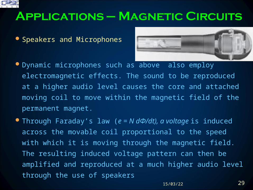
Speakers and Microphones
Dynamic microphones such as above also employ
electromagnetic effects The sound to be reproduced at a higher
audio level causes the core and attached moving coil to move
within the magnetic field of the permanent magnet
Through Faradayrsquos law (e = N dΦdt) a voltage is induced
across the movable coil proportional to the speed with which it is
moving through the magnetic field The resulting induced
voltage pattern can then be amplified and reproduced at a much
higher audio level through the use of speakers
200423 29
Computer Hard Disks
The computer hard disk stores data on a magnetic coating applied to the
surface of circular platters that spin like a record The platters are
constructed on a base of aluminium or glass (both nonferromagnetic)
which makes them rigidmdashhence the term hard disk
The magnetic coating on the platters is called the media and is of either
the oxide or the thin-film variety
200423 30
Computer Hard Disks
The information on a disk is stored around the disk in circular paths called
tracks or cylinders
In its simplest form the writeread head of a hard disk (or floppy disk) is a
U-shaped electromagnet with an air gap that rides just above the surface
of the disk
200423 31
Computer Hard Disks
As the disk rotates information in the form of a voltage with changing
polarities is applied to the winding of the electromagnet
If we energize a positive voltage level with a 1 level (of binary arithmetic)
and a negative voltage level with a 0 level the resulting magnetic flux
pattern will have the direction shown in the core
200423 32
Computer Hard Disks
When the flux pattern encounters the air gap of the core it jumps to the
magnetic material (since magnetic flux always seeks the path of least
reluctance and air has a high reluctance) and establishes a flux pattern
as shown on the disk until it reaches the other end of the core air gap
where it returns to the electromagnet and completes the path
200423 33
Computer Hard Disks
As the head moves to the next bit sector it leaves behind the
magnetic flux pattern just established from the left to the right
200423 34
Computer Hard Disks
Data reading is done by a significant change in flux occurs when the
head passes over the transition region causing a measurable voltage to
be generated across the terminals of the pickup coil as dictated by
Faradayrsquos law
200423 35
Hall Effect Sensors
The Hall effect sensor is a semiconductor device that generates an
output voltage when exposed to a magnetic field
If a magnetic field is applied as perpendicular to the direction of the
current a voltage VH will be generated between the two terminals
200423 36
Hall Effect Sensors
The force causes the electrons to accumulate in the bottom region of
the semiconductor (connected to the negative terminal of the voltage
VH) leaving a net positive charge in the upper region of the material
(connected to the positive terminal of VH)
The stronger the current or strength of the magnetic field the greater
the induced voltage VH
200423 37
Hall Effect Sensors
The most widespread use of hall effect is as a trigger for an alarm
system in large department stores where theft is often a difficult
problem
A magnetic strip attached to the merchandise sounds an alarm when a
customer passes through the exit gates without paying for the product
The sensor control current and monitoring system are housed in the
exit fence and react to the presence of the magnetic field as the product
leaves the store
When the product is paid for the cashier removes the strip or
demagnetizes the strip by applying a magnetizing force that reduces the
residual magnetism in the strip to essentially zero200423 38
Magnetic Reed Switch
200423 39
Magnetic Resonance Image (MRI or NMR vs CAT Scans)
The three major components of an MRI system are a huge
magnet that can weigh up to 100 tons a table for transporting
the patient into the circular hole in the magnet and a control
200423 40
Magnetic Resonance Image (MRI or NMR vs CAT Scans)
A strong magnetic field that causes the nuclei of certain atoms in the
body to line up
Radio waves of different frequencies are then applied to the patient in
the region of interest and if the frequency of the wave matches the
natural frequency of the atom the nuclei will be set into a state of
resonance and will absorb energy from the applied signal
200423 41
Magnetic Resonance Image (MRI or NMR vs CAT Scans)
When the signal is removed the nuclei release the acquired energy in
the form of weak but detectable signals The strength and duration of
the energy emission vary from one tissue of the body to another The
weak signals are then amplified digitized and translated to provide a
cross-sectional image
200423 42
Review
Amperersquos Circuital Law ndash (Applying KVL)
The Flux Φ ndash (Applying KCL)
Series Magnetic Circuits
Air Gaps
Series-Parallel Magnetic Circuits
Determining Flux Φ
Applications
200423 44
200423 45
200423 46
- TODAYrsquoS LECTURE CONTENTS
- Amperersquos Circuital Law ndash (KVL)
- The Flux Φ ndash (KCL)
- Series Magnetic Circuits
- Series Magnetic Circuits
- Slide 7
- Slide 8
- Slide 9
- Slide 10
- Slide 11
- Slide 12
- Slide 13
- Air Gaps
- Slide 15
- Air gaps
- Slide 17
- Series ndash Parallel Magnetic Circuits
- Determining flux φ
- Slide 20
- Slide 21
- Slide 22
- Slide 23
- Slide 24
- Slide 25
- Applications ndash Magnetic Circuits
- Slide 27
- Slide 28
- Slide 29
- Slide 30
- Slide 31
- Slide 32
- Slide 33
- Slide 34
- Slide 35
- Slide 36
- Slide 37
- Slide 38
- Slide 39
- Slide 40
- Slide 41
- Slide 42
- Summary Conclusion
- Slide 44
- Hysteresis
- Slide 46
-
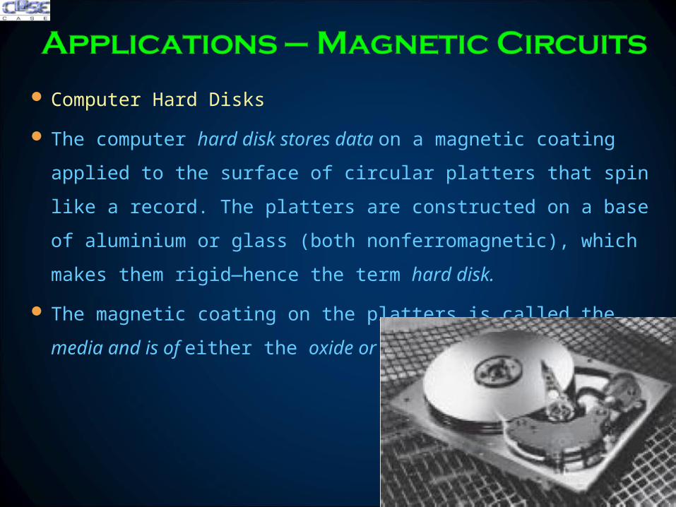
Computer Hard Disks
The computer hard disk stores data on a magnetic coating applied to the
surface of circular platters that spin like a record The platters are
constructed on a base of aluminium or glass (both nonferromagnetic)
which makes them rigidmdashhence the term hard disk
The magnetic coating on the platters is called the media and is of either
the oxide or the thin-film variety
200423 30
Computer Hard Disks
The information on a disk is stored around the disk in circular paths called
tracks or cylinders
In its simplest form the writeread head of a hard disk (or floppy disk) is a
U-shaped electromagnet with an air gap that rides just above the surface
of the disk
200423 31
Computer Hard Disks
As the disk rotates information in the form of a voltage with changing
polarities is applied to the winding of the electromagnet
If we energize a positive voltage level with a 1 level (of binary arithmetic)
and a negative voltage level with a 0 level the resulting magnetic flux
pattern will have the direction shown in the core
200423 32
Computer Hard Disks
When the flux pattern encounters the air gap of the core it jumps to the
magnetic material (since magnetic flux always seeks the path of least
reluctance and air has a high reluctance) and establishes a flux pattern
as shown on the disk until it reaches the other end of the core air gap
where it returns to the electromagnet and completes the path
200423 33
Computer Hard Disks
As the head moves to the next bit sector it leaves behind the
magnetic flux pattern just established from the left to the right
200423 34
Computer Hard Disks
Data reading is done by a significant change in flux occurs when the
head passes over the transition region causing a measurable voltage to
be generated across the terminals of the pickup coil as dictated by
Faradayrsquos law
200423 35
Hall Effect Sensors
The Hall effect sensor is a semiconductor device that generates an
output voltage when exposed to a magnetic field
If a magnetic field is applied as perpendicular to the direction of the
current a voltage VH will be generated between the two terminals
200423 36
Hall Effect Sensors
The force causes the electrons to accumulate in the bottom region of
the semiconductor (connected to the negative terminal of the voltage
VH) leaving a net positive charge in the upper region of the material
(connected to the positive terminal of VH)
The stronger the current or strength of the magnetic field the greater
the induced voltage VH
200423 37
Hall Effect Sensors
The most widespread use of hall effect is as a trigger for an alarm
system in large department stores where theft is often a difficult
problem
A magnetic strip attached to the merchandise sounds an alarm when a
customer passes through the exit gates without paying for the product
The sensor control current and monitoring system are housed in the
exit fence and react to the presence of the magnetic field as the product
leaves the store
When the product is paid for the cashier removes the strip or
demagnetizes the strip by applying a magnetizing force that reduces the
residual magnetism in the strip to essentially zero200423 38
Magnetic Reed Switch
200423 39
Magnetic Resonance Image (MRI or NMR vs CAT Scans)
The three major components of an MRI system are a huge
magnet that can weigh up to 100 tons a table for transporting
the patient into the circular hole in the magnet and a control
200423 40
Magnetic Resonance Image (MRI or NMR vs CAT Scans)
A strong magnetic field that causes the nuclei of certain atoms in the
body to line up
Radio waves of different frequencies are then applied to the patient in
the region of interest and if the frequency of the wave matches the
natural frequency of the atom the nuclei will be set into a state of
resonance and will absorb energy from the applied signal
200423 41
Magnetic Resonance Image (MRI or NMR vs CAT Scans)
When the signal is removed the nuclei release the acquired energy in
the form of weak but detectable signals The strength and duration of
the energy emission vary from one tissue of the body to another The
weak signals are then amplified digitized and translated to provide a
cross-sectional image
200423 42
Review
Amperersquos Circuital Law ndash (Applying KVL)
The Flux Φ ndash (Applying KCL)
Series Magnetic Circuits
Air Gaps
Series-Parallel Magnetic Circuits
Determining Flux Φ
Applications
200423 44
200423 45
200423 46
- TODAYrsquoS LECTURE CONTENTS
- Amperersquos Circuital Law ndash (KVL)
- The Flux Φ ndash (KCL)
- Series Magnetic Circuits
- Series Magnetic Circuits
- Slide 7
- Slide 8
- Slide 9
- Slide 10
- Slide 11
- Slide 12
- Slide 13
- Air Gaps
- Slide 15
- Air gaps
- Slide 17
- Series ndash Parallel Magnetic Circuits
- Determining flux φ
- Slide 20
- Slide 21
- Slide 22
- Slide 23
- Slide 24
- Slide 25
- Applications ndash Magnetic Circuits
- Slide 27
- Slide 28
- Slide 29
- Slide 30
- Slide 31
- Slide 32
- Slide 33
- Slide 34
- Slide 35
- Slide 36
- Slide 37
- Slide 38
- Slide 39
- Slide 40
- Slide 41
- Slide 42
- Summary Conclusion
- Slide 44
- Hysteresis
- Slide 46
-
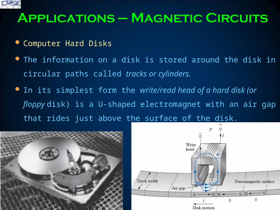
Computer Hard Disks
The information on a disk is stored around the disk in circular paths called
tracks or cylinders
In its simplest form the writeread head of a hard disk (or floppy disk) is a
U-shaped electromagnet with an air gap that rides just above the surface
of the disk
200423 31
Computer Hard Disks
As the disk rotates information in the form of a voltage with changing
polarities is applied to the winding of the electromagnet
If we energize a positive voltage level with a 1 level (of binary arithmetic)
and a negative voltage level with a 0 level the resulting magnetic flux
pattern will have the direction shown in the core
200423 32
Computer Hard Disks
When the flux pattern encounters the air gap of the core it jumps to the
magnetic material (since magnetic flux always seeks the path of least
reluctance and air has a high reluctance) and establishes a flux pattern
as shown on the disk until it reaches the other end of the core air gap
where it returns to the electromagnet and completes the path
200423 33
Computer Hard Disks
As the head moves to the next bit sector it leaves behind the
magnetic flux pattern just established from the left to the right
200423 34
Computer Hard Disks
Data reading is done by a significant change in flux occurs when the
head passes over the transition region causing a measurable voltage to
be generated across the terminals of the pickup coil as dictated by
Faradayrsquos law
200423 35
Hall Effect Sensors
The Hall effect sensor is a semiconductor device that generates an
output voltage when exposed to a magnetic field
If a magnetic field is applied as perpendicular to the direction of the
current a voltage VH will be generated between the two terminals
200423 36
Hall Effect Sensors
The force causes the electrons to accumulate in the bottom region of
the semiconductor (connected to the negative terminal of the voltage
VH) leaving a net positive charge in the upper region of the material
(connected to the positive terminal of VH)
The stronger the current or strength of the magnetic field the greater
the induced voltage VH
200423 37
Hall Effect Sensors
The most widespread use of hall effect is as a trigger for an alarm
system in large department stores where theft is often a difficult
problem
A magnetic strip attached to the merchandise sounds an alarm when a
customer passes through the exit gates without paying for the product
The sensor control current and monitoring system are housed in the
exit fence and react to the presence of the magnetic field as the product
leaves the store
When the product is paid for the cashier removes the strip or
demagnetizes the strip by applying a magnetizing force that reduces the
residual magnetism in the strip to essentially zero200423 38
Magnetic Reed Switch
200423 39
Magnetic Resonance Image (MRI or NMR vs CAT Scans)
The three major components of an MRI system are a huge
magnet that can weigh up to 100 tons a table for transporting
the patient into the circular hole in the magnet and a control
200423 40
Magnetic Resonance Image (MRI or NMR vs CAT Scans)
A strong magnetic field that causes the nuclei of certain atoms in the
body to line up
Radio waves of different frequencies are then applied to the patient in
the region of interest and if the frequency of the wave matches the
natural frequency of the atom the nuclei will be set into a state of
resonance and will absorb energy from the applied signal
200423 41
Magnetic Resonance Image (MRI or NMR vs CAT Scans)
When the signal is removed the nuclei release the acquired energy in
the form of weak but detectable signals The strength and duration of
the energy emission vary from one tissue of the body to another The
weak signals are then amplified digitized and translated to provide a
cross-sectional image
200423 42
Review
Amperersquos Circuital Law ndash (Applying KVL)
The Flux Φ ndash (Applying KCL)
Series Magnetic Circuits
Air Gaps
Series-Parallel Magnetic Circuits
Determining Flux Φ
Applications
200423 44
200423 45
200423 46
- TODAYrsquoS LECTURE CONTENTS
- Amperersquos Circuital Law ndash (KVL)
- The Flux Φ ndash (KCL)
- Series Magnetic Circuits
- Series Magnetic Circuits
- Slide 7
- Slide 8
- Slide 9
- Slide 10
- Slide 11
- Slide 12
- Slide 13
- Air Gaps
- Slide 15
- Air gaps
- Slide 17
- Series ndash Parallel Magnetic Circuits
- Determining flux φ
- Slide 20
- Slide 21
- Slide 22
- Slide 23
- Slide 24
- Slide 25
- Applications ndash Magnetic Circuits
- Slide 27
- Slide 28
- Slide 29
- Slide 30
- Slide 31
- Slide 32
- Slide 33
- Slide 34
- Slide 35
- Slide 36
- Slide 37
- Slide 38
- Slide 39
- Slide 40
- Slide 41
- Slide 42
- Summary Conclusion
- Slide 44
- Hysteresis
- Slide 46
-
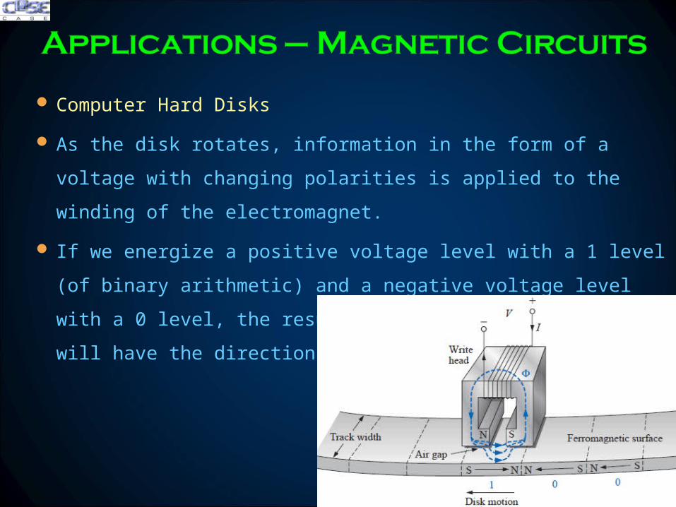
Computer Hard Disks
As the head moves to the next bit sector it leaves behind the
magnetic flux pattern just established from the left to the right
200423 34
Computer Hard Disks
Data reading is done by a significant change in flux occurs when the
head passes over the transition region causing a measurable voltage to
be generated across the terminals of the pickup coil as dictated by
Faradayrsquos law
200423 35
Hall Effect Sensors
The Hall effect sensor is a semiconductor device that generates an
output voltage when exposed to a magnetic field
If a magnetic field is applied as perpendicular to the direction of the
current a voltage VH will be generated between the two terminals
200423 36
Hall Effect Sensors
The force causes the electrons to accumulate in the bottom region of
the semiconductor (connected to the negative terminal of the voltage
VH) leaving a net positive charge in the upper region of the material
(connected to the positive terminal of VH)
The stronger the current or strength of the magnetic field the greater
the induced voltage VH
200423 37
Hall Effect Sensors
The most widespread use of hall effect is as a trigger for an alarm
system in large department stores where theft is often a difficult
problem
A magnetic strip attached to the merchandise sounds an alarm when a
customer passes through the exit gates without paying for the product
The sensor control current and monitoring system are housed in the
exit fence and react to the presence of the magnetic field as the product
leaves the store
When the product is paid for the cashier removes the strip or
demagnetizes the strip by applying a magnetizing force that reduces the
residual magnetism in the strip to essentially zero200423 38
Magnetic Reed Switch
200423 39
Magnetic Resonance Image (MRI or NMR vs CAT Scans)
The three major components of an MRI system are a huge
magnet that can weigh up to 100 tons a table for transporting
the patient into the circular hole in the magnet and a control
200423 40
Magnetic Resonance Image (MRI or NMR vs CAT Scans)
A strong magnetic field that causes the nuclei of certain atoms in the
body to line up
Radio waves of different frequencies are then applied to the patient in
the region of interest and if the frequency of the wave matches the
natural frequency of the atom the nuclei will be set into a state of
resonance and will absorb energy from the applied signal
200423 41
Magnetic Resonance Image (MRI or NMR vs CAT Scans)
When the signal is removed the nuclei release the acquired energy in
the form of weak but detectable signals The strength and duration of
the energy emission vary from one tissue of the body to another The
weak signals are then amplified digitized and translated to provide a
cross-sectional image
200423 42
Review
Amperersquos Circuital Law ndash (Applying KVL)
The Flux Φ ndash (Applying KCL)
Series Magnetic Circuits
Air Gaps
Series-Parallel Magnetic Circuits
Determining Flux Φ
Applications
200423 44
200423 45
200423 46
- TODAYrsquoS LECTURE CONTENTS
- Amperersquos Circuital Law ndash (KVL)
- The Flux Φ ndash (KCL)
- Series Magnetic Circuits
- Series Magnetic Circuits
- Slide 7
- Slide 8
- Slide 9
- Slide 10
- Slide 11
- Slide 12
- Slide 13
- Air Gaps
- Slide 15
- Air gaps
- Slide 17
- Series ndash Parallel Magnetic Circuits
- Determining flux φ
- Slide 20
- Slide 21
- Slide 22
- Slide 23
- Slide 24
- Slide 25
- Applications ndash Magnetic Circuits
- Slide 27
- Slide 28
- Slide 29
- Slide 30
- Slide 31
- Slide 32
- Slide 33
- Slide 34
- Slide 35
- Slide 36
- Slide 37
- Slide 38
- Slide 39
- Slide 40
- Slide 41
- Slide 42
- Summary Conclusion
- Slide 44
- Hysteresis
- Slide 46
-
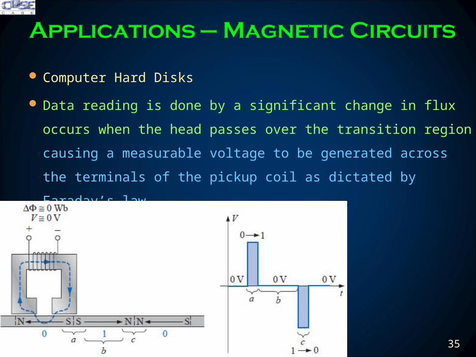
Computer Hard Disks
Data reading is done by a significant change in flux occurs when the
head passes over the transition region causing a measurable voltage to
be generated across the terminals of the pickup coil as dictated by
Faradayrsquos law
200423 35
Hall Effect Sensors
The Hall effect sensor is a semiconductor device that generates an
output voltage when exposed to a magnetic field
If a magnetic field is applied as perpendicular to the direction of the
current a voltage VH will be generated between the two terminals
200423 36
Hall Effect Sensors
The force causes the electrons to accumulate in the bottom region of
the semiconductor (connected to the negative terminal of the voltage
VH) leaving a net positive charge in the upper region of the material
(connected to the positive terminal of VH)
The stronger the current or strength of the magnetic field the greater
the induced voltage VH
200423 37
Hall Effect Sensors
The most widespread use of hall effect is as a trigger for an alarm
system in large department stores where theft is often a difficult
problem
A magnetic strip attached to the merchandise sounds an alarm when a
customer passes through the exit gates without paying for the product
The sensor control current and monitoring system are housed in the
exit fence and react to the presence of the magnetic field as the product
leaves the store
When the product is paid for the cashier removes the strip or
demagnetizes the strip by applying a magnetizing force that reduces the
residual magnetism in the strip to essentially zero200423 38
Magnetic Reed Switch
200423 39
Magnetic Resonance Image (MRI or NMR vs CAT Scans)
The three major components of an MRI system are a huge
magnet that can weigh up to 100 tons a table for transporting
the patient into the circular hole in the magnet and a control
200423 40
Magnetic Resonance Image (MRI or NMR vs CAT Scans)
A strong magnetic field that causes the nuclei of certain atoms in the
body to line up
Radio waves of different frequencies are then applied to the patient in
the region of interest and if the frequency of the wave matches the
natural frequency of the atom the nuclei will be set into a state of
resonance and will absorb energy from the applied signal
200423 41
Magnetic Resonance Image (MRI or NMR vs CAT Scans)
When the signal is removed the nuclei release the acquired energy in
the form of weak but detectable signals The strength and duration of
the energy emission vary from one tissue of the body to another The
weak signals are then amplified digitized and translated to provide a
cross-sectional image
200423 42
Review
Amperersquos Circuital Law ndash (Applying KVL)
The Flux Φ ndash (Applying KCL)
Series Magnetic Circuits
Air Gaps
Series-Parallel Magnetic Circuits
Determining Flux Φ
Applications
200423 44
200423 45
200423 46
- TODAYrsquoS LECTURE CONTENTS
- Amperersquos Circuital Law ndash (KVL)
- The Flux Φ ndash (KCL)
- Series Magnetic Circuits
- Series Magnetic Circuits
- Slide 7
- Slide 8
- Slide 9
- Slide 10
- Slide 11
- Slide 12
- Slide 13
- Air Gaps
- Slide 15
- Air gaps
- Slide 17
- Series ndash Parallel Magnetic Circuits
- Determining flux φ
- Slide 20
- Slide 21
- Slide 22
- Slide 23
- Slide 24
- Slide 25
- Applications ndash Magnetic Circuits
- Slide 27
- Slide 28
- Slide 29
- Slide 30
- Slide 31
- Slide 32
- Slide 33
- Slide 34
- Slide 35
- Slide 36
- Slide 37
- Slide 38
- Slide 39
- Slide 40
- Slide 41
- Slide 42
- Summary Conclusion
- Slide 44
- Hysteresis
- Slide 46
-
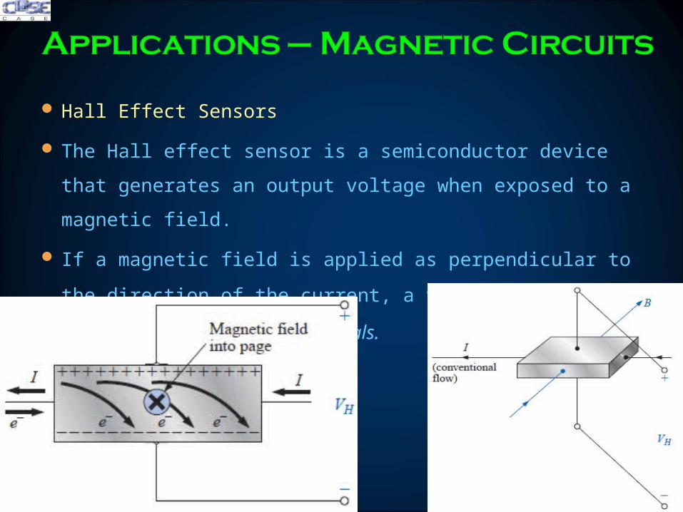
Hall Effect Sensors
The Hall effect sensor is a semiconductor device that generates an
output voltage when exposed to a magnetic field
If a magnetic field is applied as perpendicular to the direction of the
current a voltage VH will be generated between the two terminals
200423 36
Hall Effect Sensors
The force causes the electrons to accumulate in the bottom region of
the semiconductor (connected to the negative terminal of the voltage
VH) leaving a net positive charge in the upper region of the material
(connected to the positive terminal of VH)
The stronger the current or strength of the magnetic field the greater
the induced voltage VH
200423 37
Hall Effect Sensors
The most widespread use of hall effect is as a trigger for an alarm
system in large department stores where theft is often a difficult
problem
A magnetic strip attached to the merchandise sounds an alarm when a
customer passes through the exit gates without paying for the product
The sensor control current and monitoring system are housed in the
exit fence and react to the presence of the magnetic field as the product
leaves the store
When the product is paid for the cashier removes the strip or
demagnetizes the strip by applying a magnetizing force that reduces the
residual magnetism in the strip to essentially zero200423 38
Magnetic Reed Switch
200423 39
Magnetic Resonance Image (MRI or NMR vs CAT Scans)
The three major components of an MRI system are a huge
magnet that can weigh up to 100 tons a table for transporting
the patient into the circular hole in the magnet and a control
200423 40
Magnetic Resonance Image (MRI or NMR vs CAT Scans)
A strong magnetic field that causes the nuclei of certain atoms in the
body to line up
Radio waves of different frequencies are then applied to the patient in
the region of interest and if the frequency of the wave matches the
natural frequency of the atom the nuclei will be set into a state of
resonance and will absorb energy from the applied signal
200423 41
Magnetic Resonance Image (MRI or NMR vs CAT Scans)
When the signal is removed the nuclei release the acquired energy in
the form of weak but detectable signals The strength and duration of
the energy emission vary from one tissue of the body to another The
weak signals are then amplified digitized and translated to provide a
cross-sectional image
200423 42
Review
Amperersquos Circuital Law ndash (Applying KVL)
The Flux Φ ndash (Applying KCL)
Series Magnetic Circuits
Air Gaps
Series-Parallel Magnetic Circuits
Determining Flux Φ
Applications
200423 44
200423 45
200423 46
- TODAYrsquoS LECTURE CONTENTS
- Amperersquos Circuital Law ndash (KVL)
- The Flux Φ ndash (KCL)
- Series Magnetic Circuits
- Series Magnetic Circuits
- Slide 7
- Slide 8
- Slide 9
- Slide 10
- Slide 11
- Slide 12
- Slide 13
- Air Gaps
- Slide 15
- Air gaps
- Slide 17
- Series ndash Parallel Magnetic Circuits
- Determining flux φ
- Slide 20
- Slide 21
- Slide 22
- Slide 23
- Slide 24
- Slide 25
- Applications ndash Magnetic Circuits
- Slide 27
- Slide 28
- Slide 29
- Slide 30
- Slide 31
- Slide 32
- Slide 33
- Slide 34
- Slide 35
- Slide 36
- Slide 37
- Slide 38
- Slide 39
- Slide 40
- Slide 41
- Slide 42
- Summary Conclusion
- Slide 44
- Hysteresis
- Slide 46
-
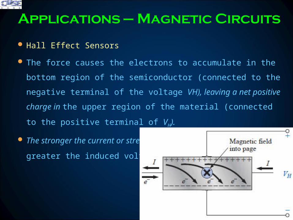
Hall Effect Sensors
The force causes the electrons to accumulate in the bottom region of
the semiconductor (connected to the negative terminal of the voltage
VH) leaving a net positive charge in the upper region of the material
(connected to the positive terminal of VH)
The stronger the current or strength of the magnetic field the greater
the induced voltage VH
200423 37
Hall Effect Sensors
The most widespread use of hall effect is as a trigger for an alarm
system in large department stores where theft is often a difficult
problem
A magnetic strip attached to the merchandise sounds an alarm when a
customer passes through the exit gates without paying for the product
The sensor control current and monitoring system are housed in the
exit fence and react to the presence of the magnetic field as the product
leaves the store
When the product is paid for the cashier removes the strip or
demagnetizes the strip by applying a magnetizing force that reduces the
residual magnetism in the strip to essentially zero200423 38
Magnetic Reed Switch
200423 39
Magnetic Resonance Image (MRI or NMR vs CAT Scans)
The three major components of an MRI system are a huge
magnet that can weigh up to 100 tons a table for transporting
the patient into the circular hole in the magnet and a control
200423 40
Magnetic Resonance Image (MRI or NMR vs CAT Scans)
A strong magnetic field that causes the nuclei of certain atoms in the
body to line up
Radio waves of different frequencies are then applied to the patient in
the region of interest and if the frequency of the wave matches the
natural frequency of the atom the nuclei will be set into a state of
resonance and will absorb energy from the applied signal
200423 41
Magnetic Resonance Image (MRI or NMR vs CAT Scans)
When the signal is removed the nuclei release the acquired energy in
the form of weak but detectable signals The strength and duration of
the energy emission vary from one tissue of the body to another The
weak signals are then amplified digitized and translated to provide a
cross-sectional image
200423 42
Review
Amperersquos Circuital Law ndash (Applying KVL)
The Flux Φ ndash (Applying KCL)
Series Magnetic Circuits
Air Gaps
Series-Parallel Magnetic Circuits
Determining Flux Φ
Applications
200423 44
200423 45
200423 46
- TODAYrsquoS LECTURE CONTENTS
- Amperersquos Circuital Law ndash (KVL)
- The Flux Φ ndash (KCL)
- Series Magnetic Circuits
- Series Magnetic Circuits
- Slide 7
- Slide 8
- Slide 9
- Slide 10
- Slide 11
- Slide 12
- Slide 13
- Air Gaps
- Slide 15
- Air gaps
- Slide 17
- Series ndash Parallel Magnetic Circuits
- Determining flux φ
- Slide 20
- Slide 21
- Slide 22
- Slide 23
- Slide 24
- Slide 25
- Applications ndash Magnetic Circuits
- Slide 27
- Slide 28
- Slide 29
- Slide 30
- Slide 31
- Slide 32
- Slide 33
- Slide 34
- Slide 35
- Slide 36
- Slide 37
- Slide 38
- Slide 39
- Slide 40
- Slide 41
- Slide 42
- Summary Conclusion
- Slide 44
- Hysteresis
- Slide 46
-
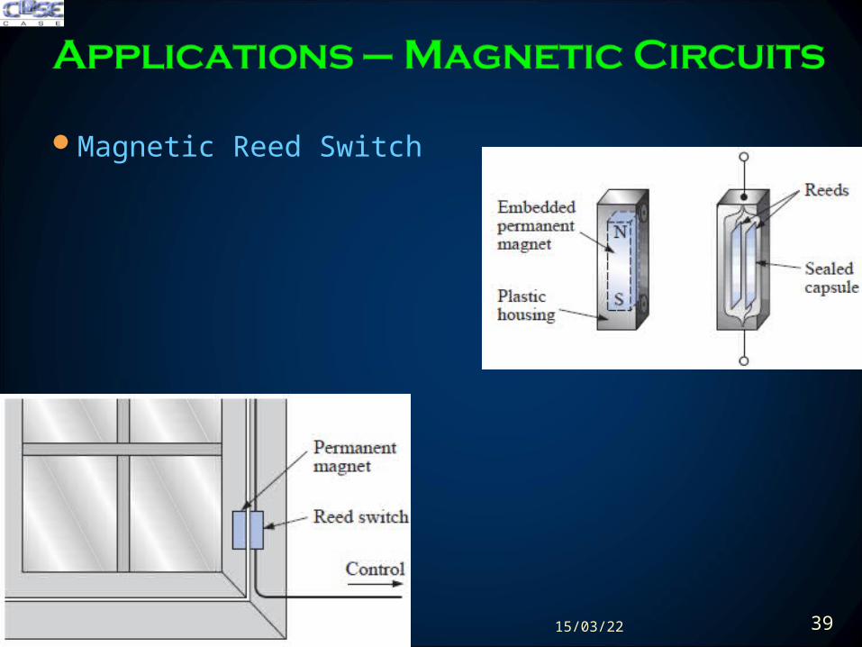

Magnetic Resonance Image (MRI or NMR vs CAT Scans)
The three major components of an MRI system are a huge
magnet that can weigh up to 100 tons a table for transporting
the patient into the circular hole in the magnet and a control
200423 40
Magnetic Resonance Image (MRI or NMR vs CAT Scans)
A strong magnetic field that causes the nuclei of certain atoms in the
body to line up
Radio waves of different frequencies are then applied to the patient in
the region of interest and if the frequency of the wave matches the
natural frequency of the atom the nuclei will be set into a state of
resonance and will absorb energy from the applied signal
200423 41
Magnetic Resonance Image (MRI or NMR vs CAT Scans)
When the signal is removed the nuclei release the acquired energy in
the form of weak but detectable signals The strength and duration of
the energy emission vary from one tissue of the body to another The
weak signals are then amplified digitized and translated to provide a
cross-sectional image
200423 42
Review
Amperersquos Circuital Law ndash (Applying KVL)
The Flux Φ ndash (Applying KCL)
Series Magnetic Circuits
Air Gaps
Series-Parallel Magnetic Circuits
Determining Flux Φ
Applications
200423 44
200423 45
200423 46
- TODAYrsquoS LECTURE CONTENTS
- Amperersquos Circuital Law ndash (KVL)
- The Flux Φ ndash (KCL)
- Series Magnetic Circuits
- Series Magnetic Circuits
- Slide 7
- Slide 8
- Slide 9
- Slide 10
- Slide 11
- Slide 12
- Slide 13
- Air Gaps
- Slide 15
- Air gaps
- Slide 17
- Series ndash Parallel Magnetic Circuits
- Determining flux φ
- Slide 20
- Slide 21
- Slide 22
- Slide 23
- Slide 24
- Slide 25
- Applications ndash Magnetic Circuits
- Slide 27
- Slide 28
- Slide 29
- Slide 30
- Slide 31
- Slide 32
- Slide 33
- Slide 34
- Slide 35
- Slide 36
- Slide 37
- Slide 38
- Slide 39
- Slide 40
- Slide 41
- Slide 42
- Summary Conclusion
- Slide 44
- Hysteresis
- Slide 46
-
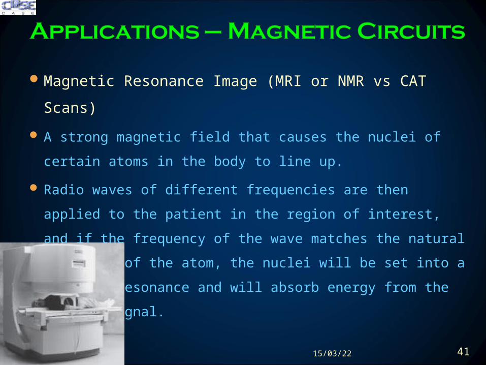
Magnetic Resonance Image (MRI or NMR vs CAT Scans)
A strong magnetic field that causes the nuclei of certain atoms in the
body to line up
Radio waves of different frequencies are then applied to the patient in
the region of interest and if the frequency of the wave matches the
natural frequency of the atom the nuclei will be set into a state of
resonance and will absorb energy from the applied signal
200423 41
Magnetic Resonance Image (MRI or NMR vs CAT Scans)
When the signal is removed the nuclei release the acquired energy in
the form of weak but detectable signals The strength and duration of
the energy emission vary from one tissue of the body to another The
weak signals are then amplified digitized and translated to provide a
cross-sectional image
200423 42
Review
Amperersquos Circuital Law ndash (Applying KVL)
The Flux Φ ndash (Applying KCL)
Series Magnetic Circuits
Air Gaps
Series-Parallel Magnetic Circuits
Determining Flux Φ
Applications
200423 44
200423 45
200423 46
- TODAYrsquoS LECTURE CONTENTS
- Amperersquos Circuital Law ndash (KVL)
- The Flux Φ ndash (KCL)
- Series Magnetic Circuits
- Series Magnetic Circuits
- Slide 7
- Slide 8
- Slide 9
- Slide 10
- Slide 11
- Slide 12
- Slide 13
- Air Gaps
- Slide 15
- Air gaps
- Slide 17
- Series ndash Parallel Magnetic Circuits
- Determining flux φ
- Slide 20
- Slide 21
- Slide 22
- Slide 23
- Slide 24
- Slide 25
- Applications ndash Magnetic Circuits
- Slide 27
- Slide 28
- Slide 29
- Slide 30
- Slide 31
- Slide 32
- Slide 33
- Slide 34
- Slide 35
- Slide 36
- Slide 37
- Slide 38
- Slide 39
- Slide 40
- Slide 41
- Slide 42
- Summary Conclusion
- Slide 44
- Hysteresis
- Slide 46
-
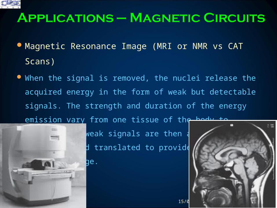
Magnetic Resonance Image (MRI or NMR vs CAT Scans)
When the signal is removed the nuclei release the acquired energy in
the form of weak but detectable signals The strength and duration of
the energy emission vary from one tissue of the body to another The
weak signals are then amplified digitized and translated to provide a
cross-sectional image
200423 42
Review
Amperersquos Circuital Law ndash (Applying KVL)
The Flux Φ ndash (Applying KCL)
Series Magnetic Circuits
Air Gaps
Series-Parallel Magnetic Circuits
Determining Flux Φ
Applications
200423 44
200423 45
200423 46
- TODAYrsquoS LECTURE CONTENTS
- Amperersquos Circuital Law ndash (KVL)
- The Flux Φ ndash (KCL)
- Series Magnetic Circuits
- Series Magnetic Circuits
- Slide 7
- Slide 8
- Slide 9
- Slide 10
- Slide 11
- Slide 12
- Slide 13
- Air Gaps
- Slide 15
- Air gaps
- Slide 17
- Series ndash Parallel Magnetic Circuits
- Determining flux φ
- Slide 20
- Slide 21
- Slide 22
- Slide 23
- Slide 24
- Slide 25
- Applications ndash Magnetic Circuits
- Slide 27
- Slide 28
- Slide 29
- Slide 30
- Slide 31
- Slide 32
- Slide 33
- Slide 34
- Slide 35
- Slide 36
- Slide 37
- Slide 38
- Slide 39
- Slide 40
- Slide 41
- Slide 42
- Summary Conclusion
- Slide 44
- Hysteresis
- Slide 46
-
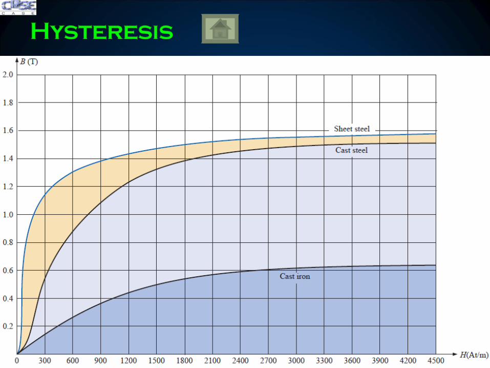
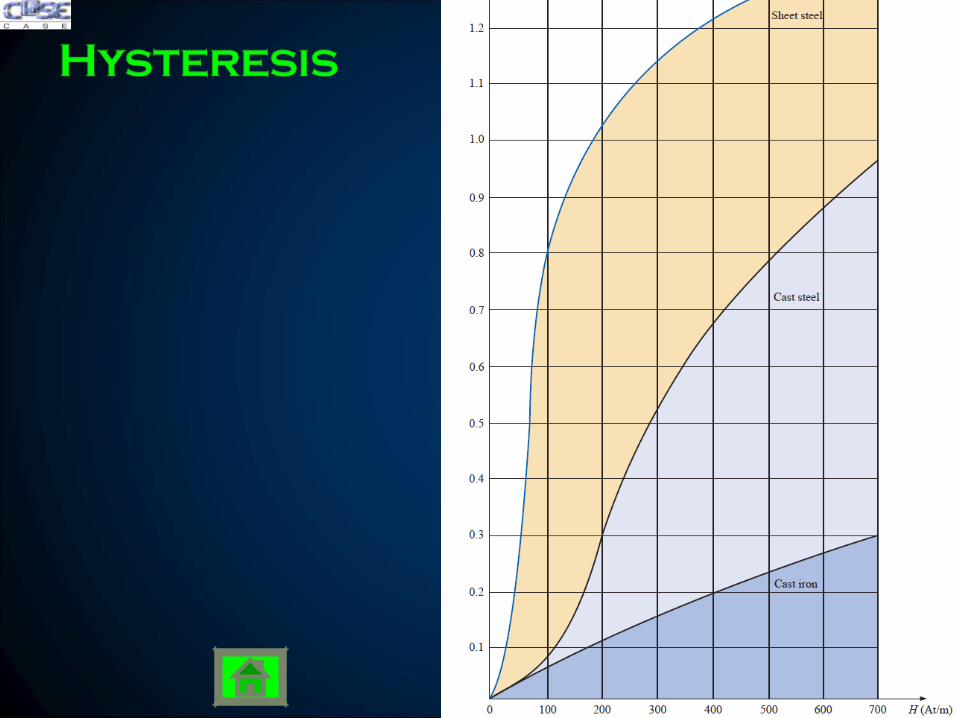