Chalcogenide IR-Glass Fiber (CIR Fiber) - Sintec … · Chalcogenide IR-Glass Fiber (CIR Fiber) ......
12
Sintec Optronics Technology Pte Ltd http://www.SintecOptronics.com http://www.SintecOptronics.com.sg 1 Chalcogenide IR-Glass Fiber (CIR Fiber) Chalcogenide Infra Red (CIR) glasses are the best As 2 S 3 -based material for fiber optics in the range of 1.5-6μm. CIR fibers transmit IR-radiation in the gap between silica fibers (0.2-2.4μm) and Polycrystalline Infra Red (PIR) fibers (4-18μm). CIR fiber is drawn in core/clad structure with double polymer coating and characterized by a low optical losses and high flexibility. The innovative glass purification process provides the attenuation spectra free from OH absorption band at 3μm and thus it enables CIR fiber to be used for Er:YAG laser power delivery. Features • high transmittance from 1.5μm up to 6μm • suitable for Er:YAG - laser power delivery • optical losses 0.2 dB/m at 2-4μm • double polymer coating for high flexibility • durable cables with SMA-connectors Applications • Flexible delivery for Er:YAG - laser • flexible IR-imaging systems • remote non-contact pyrometry in the 200-600K range • fiber probes for remote process IR - spectroscopy Fiber specification Transmission Range 1.5 - 6μm Core/Clad Structure As2S3/As-S Core/Clad Diameter 200-500/300-600μm Core Refractive Index 2.4 Effective NA 0.28 Protective Coating Double Polymer Jacket Ambient Temperature Range 270 - 370 K CIR Infrared Optical Fiber Standard Cables Chalcogenide Infra Red (CIR) (1.5 - 6μm) fiber is drawn in core/clad structure with double polymer coating and characterized by a low optical losses and high flexibility. Delivery is from stock or within few weeks ARO. All standard cables include PEEK-polymer protective jacket and SMA termination. Sintec Optronics Technology Pte Ltd 10 Bukit Batok Crescent #07-02 The Spire Singapore 658079 Tel: +65 63167112 Fax: +65 63167113
Transcript of Chalcogenide IR-Glass Fiber (CIR Fiber) - Sintec … · Chalcogenide IR-Glass Fiber (CIR Fiber) ......
Sintec Optronics Technology Pte Ltd
http://www.SintecOptronics.com http://www.SintecOptronics.com.sg 1
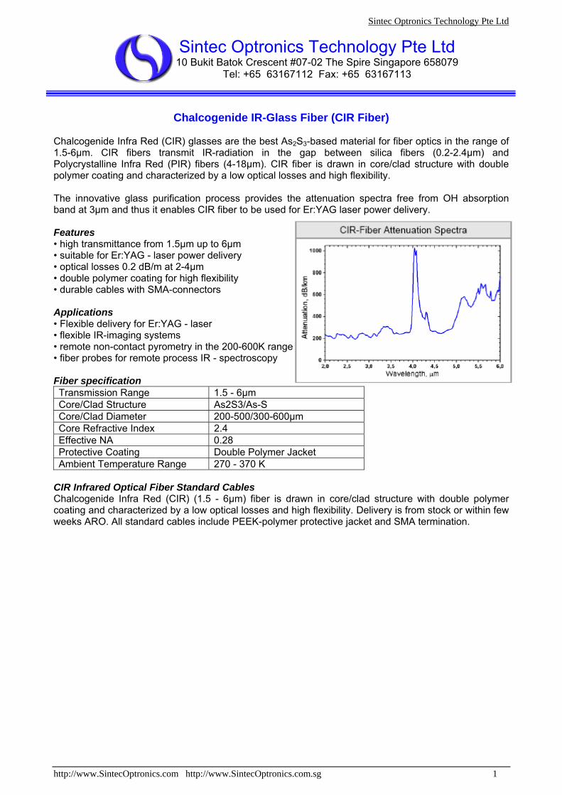
Chalcogenide IR-Glass Fiber (CIR Fiber) Chalcogenide Infra Red (CIR) glasses are the best As2S3-based material for fiber optics in the range of 1.5-6μm. CIR fibers transmit IR-radiation in the gap between silica fibers (0.2-2.4μm) and Polycrystalline Infra Red (PIR) fibers (4-18μm). CIR fiber is drawn in core/clad structure with double polymer coating and characterized by a low optical losses and high flexibility. The innovative glass purification process provides the attenuation spectra free from OH absorption band at 3μm and thus it enables CIR fiber to be used for Er:YAG laser power delivery. Features • high transmittance from 1.5μm up to 6μm • suitable for Er:YAG - laser power delivery • optical losses 0.2 dB/m at 2-4μm • double polymer coating for high flexibility • durable cables with SMA-connectors Applications • Flexible delivery for Er:YAG - laser • flexible IR-imaging systems • remote non-contact pyrometry in the 200-600K range • fiber probes for remote process IR - spectroscopy Fiber specification Transmission Range 1.5 - 6μm Core/Clad Structure As2S3/As-S Core/Clad Diameter 200-500/300-600μm Core Refractive Index 2.4 Effective NA 0.28 Protective Coating Double Polymer Jacket Ambient Temperature Range 270 - 370 K
CIR Infrared Optical Fiber Standard Cables Chalcogenide Infra Red (CIR) (1.5 - 6μm) fiber is drawn in core/clad structure with double polymer coating and characterized by a low optical losses and high flexibility. Delivery is from stock or within few weeks ARO. All standard cables include PEEK-polymer protective jacket and SMA termination.
Sintec Optronics Technology Pte Ltd 10 Bukit Batok Crescent #07-02 The Spire Singapore 658079
Tel: +65 63167112 Fax: +65 63167113
Sintec Optronics Technology Pte Ltd
http://www.SintecOptronics.com http://www.SintecOptronics.com.sg 2
Polycrystalline Infra Red Fibers (PIR – Fibers)
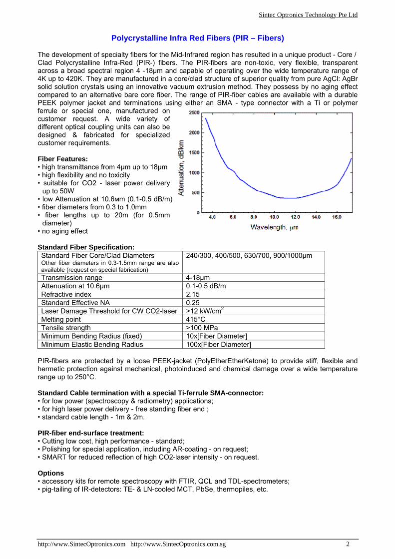
The development of specialty fibers for the Mid-Infrared region has resulted in a unique product - Core / Clad Polycrystalline Infra-Red (PIR-) fibers. The PIR-fibers are non-toxic, very flexible, transparent across a broad spectral region 4 -18μm and capable of operating over the wide temperature range of 4K up to 420K. They are manufactured in a core/clad structure of superior quality from pure AgCl: AgBr solid solution crystals using an innovative vacuum extrusion method. They possess by no aging effect compared to an alternative bare core fiber. The range of PIR-fiber cables are available with a durable PEEK polymer jacket and terminations using either an SMA - type connector with a Ti or polymer ferrule or special one, manufactured on customer request. A wide variety of different optical coupling units can also be designed & fabricated for specialized customer requirements. Fiber Features: • high transmittance from 4μm up to 18μm • high flexibility and no toxicity • suitable for CO2 - laser power delivery
up to 50W • low Attenuation at 10.6мm (0.1-0.5 dB/m) • fiber diameters from 0.3 to 1.0mm • fiber lengths up to 20m (for 0.5mm
diameter) • no aging effect Standard Fiber Specification: Standard Fiber Core/Clad Diameters Other fiber diameters in 0.3-1.5mm range are also available (request on special fabrication)
240/300, 400/500, 630/700, 900/1000μm
Transmission range 4-18μm Attenuation at 10.6μm 0.1-0.5 dB/m Refractive index 2.15 Standard Effective NA 0.25 Laser Damage Threshold for CW CO2-laser >12 kW/cm2 Melting point 415°C Tensile strength >100 MPa Minimum Bending Radius (fixed) 10x[Fiber Diameter] Minimum Elastic Bending Radius 100x[Fiber Diameter]
PIR-fibers are protected by a loose PEEK-jacket (PolyEtherEtherKetone) to provide stiff, flexible and hermetic protection against mechanical, photoinduced and chemical damage over a wide temperature range up to 250°C. Standard Cable termination with a special Ti-ferrule SMA-connector: • for low power (spectroscopy & radiometry) applications; • for high laser power delivery - free standing fiber end ; • standard cable length - 1m & 2m. PIR-fiber end-surface treatment: • Cutting low cost, high performance - standard; • Polishing for special application, including AR-coating - on request; • SMART for reduced reflection of high CO2-laser intensity - on request. Options • accessory kits for remote spectroscopy with FTIR, QCL and TDL-spectrometers; • pig-tailing of IR-detectors: TE- & LN-cooled MCT, PbSe, thermopiles, etc.
Sintec Optronics Technology Pte Ltd
http://www.SintecOptronics.com http://www.SintecOptronics.com.sg 3
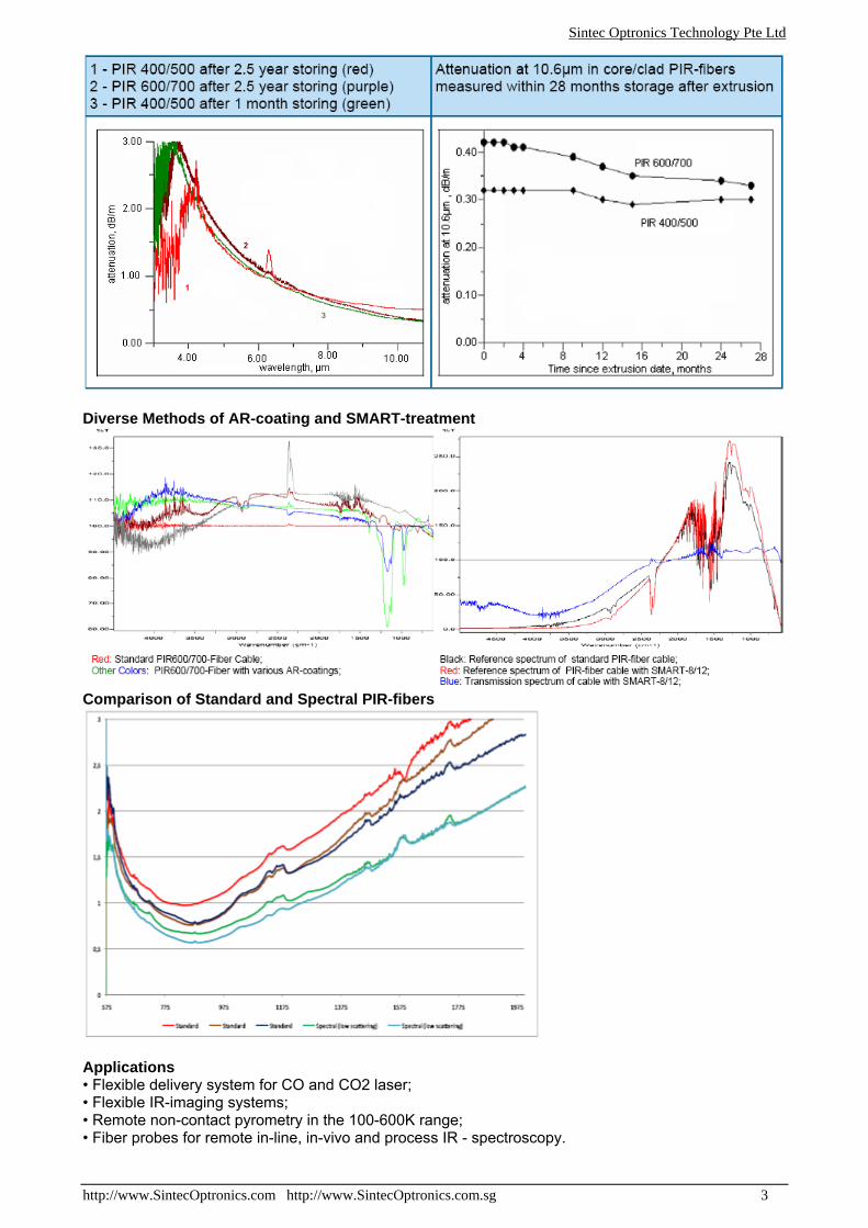
Diverse Methods of AR-coating and SMART-treatment
Comparison of Standard and Spectral PIR-fibers
Applications • Flexible delivery system for CO and CO2 laser; • Flexible IR-imaging systems; • Remote non-contact pyrometry in the 100-600K range; • Fiber probes for remote in-line, in-vivo and process IR - spectroscopy.
Sintec Optronics Technology Pte Ltd
http://www.SintecOptronics.com http://www.SintecOptronics.com.sg 4
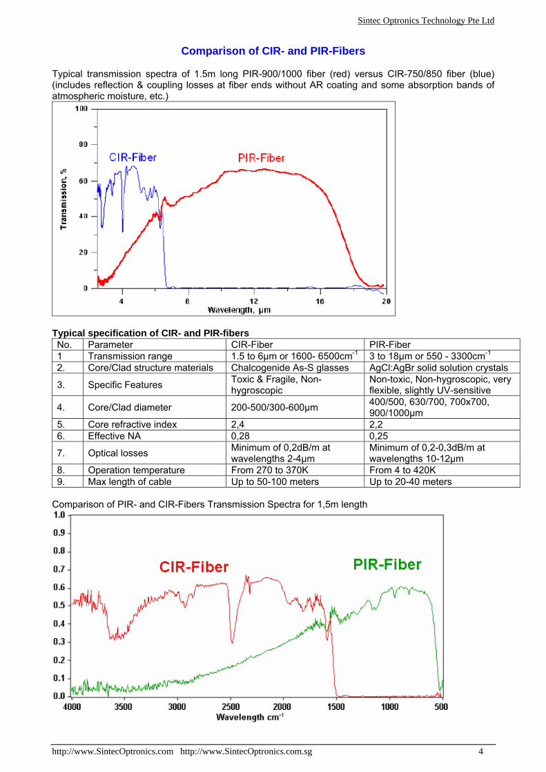
Comparison of CIR- and PIR-Fibers
Typical transmission spectra of 1.5m long PIR-900/1000 fiber (red) versus CIR-750/850 fiber (blue) (includes reflection & coupling losses at fiber ends without AR coating and some absorption bands of atmospheric moisture, etc.)
Typical specification of CIR- and PIR-fibers No. Parameter CIR-Fiber PIR-Fiber 1 Transmission range 1.5 to 6μm or 1600- 6500cm-1 3 to 18μm or 550 - 3300cm-1 2. Core/Clad structure materials Chalcogenide As-S glasses AgCl:AgBr solid solution crystals
3. Specific Features Toxic & Fragile, Non-hygroscopic
Non-toxic, Non-hygroscopic, very flexible, slightly UV-sensitive
4. Core/Clad diameter 200-500/300-600μm 400/500, 630/700, 700x700, 900/1000μm
5. Core refractive index 2,4 2,2 6. Effective NA 0,28 0,25
7. Optical losses Minimum of 0,2dB/m at wavelengths 2-4μm
Minimum of 0,2-0,3dB/m at wavelengths 10-12μm
8. Operation temperature From 270 to 370K From 4 to 420K 9. Max length of cable Up to 50-100 meters Up to 20-40 meters
Comparison of PIR- and CIR-Fibers Transmission Spectra for 1,5m length
Sintec Optronics Technology Pte Ltd
http://www.SintecOptronics.com http://www.SintecOptronics.com.sg 5
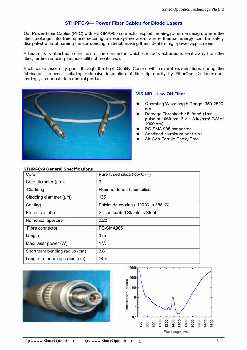
STHPFC-9— Power Fiber Cables for Diode Lasers
Our Power Fiber Cables (PFC) with PC-SMA905 connector exploit the air-gap-ferrule design, where the fiber prolongs into free space securing an epoxy-free area, where thermal energy can be safely dissipated without burning the surrounding material, making them ideal for high-power applications. A heat-sink is attached to the rear of the connector, which conducts extraneous heat away from the fiber, further reducing the possibility of breakdown. Each cable assembly goes through the tight Quality Control with several examinations during the fabrication process, including extensive inspection of fiber tip quality by FiberCheck® technique, leading , as a result, to a special product.
VIS-NIR—Low OH Fiber
Operating Wavelength Range: 350-2500 nm
Damage Threshold: >5J/mm² (1ms pulse at 1060 nm, & > 1.3 kJ/mm² CW at 1060 nm)
PC-SMA 905 connector Anodized aluminum heat sink Air-Gap-Ferrule Epoxy Free
STHPFC-9 General Specifications Core
Core diameter (μm)
Pure fused silica (low OH-)
9
Cladding
Cladding diameter (μm)
Fluorine doped fused silica
135
Coating Polyimide coating (-190°C to 385: C)
Protective tube Silicon coated Stainless Steel
Numerical aperture 0.22
Fibre connector
Length
PC-SMA905
3 m
Max. laser power (W) 1 W
Short term bending radius (cm)
Long term bending radius (cm)
3.6
14.4

Sintec Optronics Technology Pte Ltd
http://www.SintecOptronics.com http://www.SintecOptronics.com.sg 6
PIR-fiber delivery set for CO2 laser
A medical laser delivery system is destinated for transmission energy of laser to a surgical site of a patient. Application
Used in: Stomatology, Urology, Proctology
1) Adjustable coupler to laser head
2) Hermetic unit
3) PIR-fiber cable Includes
4) Focusing handpiece
Total transmission (1.5 m length) >70%
Maximum input power 50 W CW Common features
Minimal bending radius 10 cm
Focusing handpiece diameter max 22 mm
Focusing handpiece length max 100 mm
Focal spot size 0.65-0.9 mm
Operating distance away from lens 20 mm
Focusing handpiece
Operating distance away from exit 3-4 mm
PIR-Fiber cable According to PIR-fiber specifications, in PEEK tubing and outer jacket, carrying cooling gas, Ti-SMA-connectors
Maximal laser beam diameter 8 mm
Diameter 30 mm
Length (with hermetic unit) 140 mm Coupler to laser head
Connecting dimensions Screw M30x1
Nipple dia 6 mm Hermetic unit
Cooling gas pressure 0.1-0.15 atm
Sintec Optronics Technology Pte Ltd
http://www.SintecOptronics.com http://www.SintecOptronics.com.sg 7
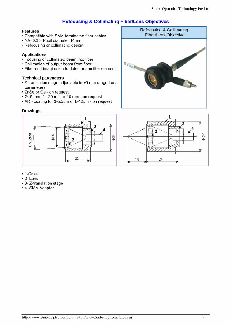
Refocusing & Collimating Fiber/Lens Objectives
Features • Compatible with SMA-terminated fiber cables • NA=0.35, Pupil diameter 14 mm • Refocusing or collimating design Applications • Focusing of collimated beam into fiber • Collimation of output beam from fiber • Fiber end imagination to detector / emitter element Technical parameters • Z-translation stage adjustable in ±5 mm range Lens
parameters • ZnSe or Ge - on request • Ø15 mm; f = 20 mm or 10 mm - on request • AR - coating for 3-5.5μm or 8-12μm - on request Drawings
• 1-Case • 2- Lens • 3- Z-translation stage • 4- SMA-Adaptor
Sintec Optronics Technology Pte Ltd
http://www.SintecOptronics.com http://www.SintecOptronics.com.sg 8
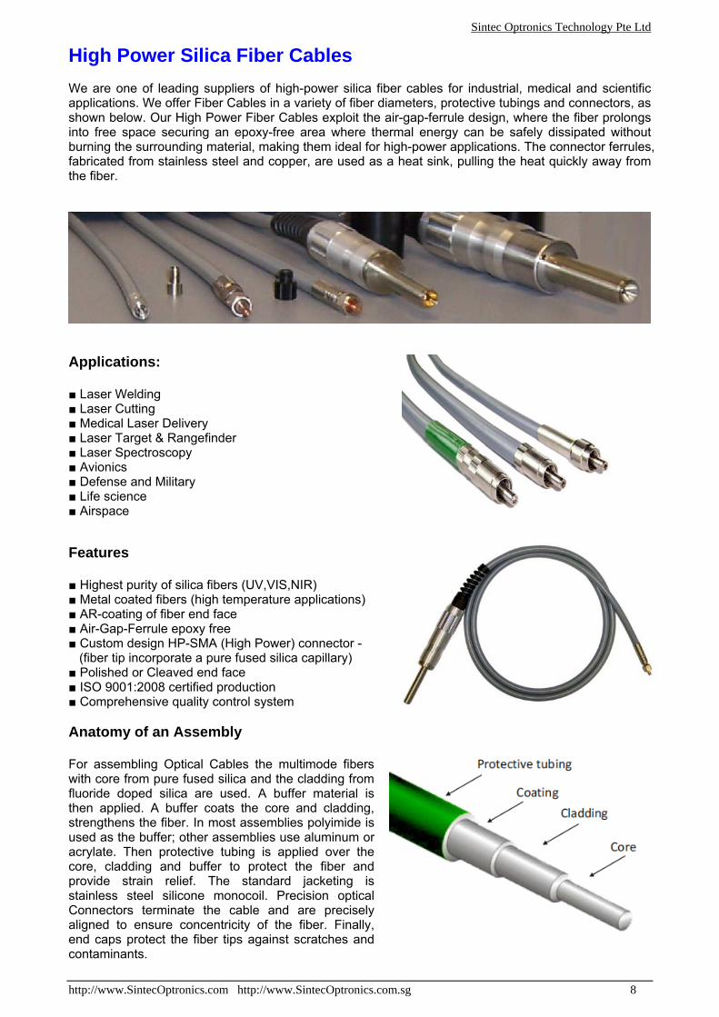
High Power Silica Fiber Cables We are one of leading suppliers of high-power silica fiber cables for industrial, medical and scientific applications. We offer Fiber Cables in a variety of fiber diameters, protective tubings and connectors, as shown below. Our High Power Fiber Cables exploit the air-gap-ferrule design, where the fiber prolongs into free space securing an epoxy-free area where thermal energy can be safely dissipated without burning the surrounding material, making them ideal for high-power applications. The connector ferrules, fabricated from stainless steel and copper, are used as a heat sink, pulling the heat quickly away from the fiber.
Applications: ■ Laser Welding ■ Laser Cutting ■ Medical Laser Delivery ■ Laser Target & Rangefinder ■ Laser Spectroscopy ■ Avionics ■ Defense and Military ■ Life science ■ Airspace
Features ■ Highest purity of silica fibers (UV,VIS,NIR) ■ Metal coated fibers (high temperature applications) ■ AR-coating of fiber end face ■ Air-Gap-Ferrule epoxy free ■ Custom design HP-SMA (High Power) connector - (fiber tip incorporate a pure fused silica capillary) ■ Polished or Cleaved end face ■ ISO 9001:2008 certified production ■ Comprehensive quality control system Anatomy of an Assembly For assembling Optical Cables the multimode fibers with core from pure fused silica and the cladding from fluoride doped silica are used. A buffer material is then applied. A buffer coats the core and cladding, strengthens the fiber. In most assemblies polyimide is used as the buffer; other assemblies use aluminum or acrylate. Then protective tubing is applied over the core, cladding and buffer to protect the fiber and provide strain relief. The standard jacketing is stainless steel silicone monocoil. Precision optical Connectors terminate the cable and are precisely aligned to ensure concentricity of the fiber. Finally, end caps protect the fiber tips against scratches and contaminants.
Sintec Optronics Technology Pte Ltd
http://www.SintecOptronics.com http://www.SintecOptronics.com.sg 9
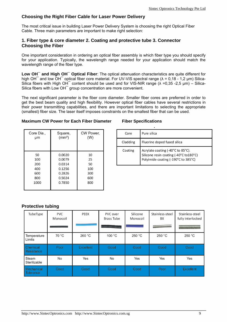
Choosing the Right Fiber Cable for Laser Power Delivery The most critical issue in building Laser Power Delivery System is choosing the right Optical Fiber Cable. Three main parameters are important to make right selection: 1. Fiber type & core diameter 2. Coating and protective tube 3. Connector Choosing the Fiber One important consideration in ordering an optical fiber assembly is which fiber type you should specify for your application. Typically, the wavelength range needed for your application should match the wavelength range of the fiber type. Low OH¯ and High OH¯ Optical Fiber: The optical attenuation characteristics are quite different for high OH¯ and low OH¯ optical fiber core material. For UV-VIS spectral range (λ = 0,18 - 1,2 μm) Silica-Silica fibers with High OH¯ content should be used and for VIS-NIR range (λ =0,35 -2,5 μm) – Silica-Silica fibers with Low OH¯ group concentration are more convenient. The next significant parameter is the fiber core diameter. Smaller fiber cores are preferred in order to get the best beam quality and high flexibility. However optical fiber cables have several restrictions in their power transmitting capabilities, and there are important limitations to selecting the appropriate (smallest) fiber size. The laser itself imposes constraints on the smallest fiber that can be used. Maximum CW Power for Each Fiber Diameter Fiber Specifications
Protective tubing
Sintec Optronics Technology Pte Ltd
http://www.SintecOptronics.com http://www.SintecOptronics.com.sg 10
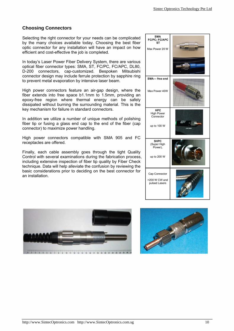
Choosing Connectors Selecting the right connector for your needs can be complicated by the many choices available today. Choosing the best fiber optic connector for any installation will have an impact on how efficient and cost-effective the job is completed. In today’s Laser Power Fiber Delivery System, there are various optical fiber connector types: SMA, ST, FC/PC, FC/APC, DL80, D-200 connectors, cap-customized. Bespoken Mitsubishi connector design may include ferrule protection by sapphire ring to prevent metal evaporation by intensive laser beam. High power connectors feature an air-gap design, where the fiber extends into free space b1.1mm to 1.5mm, providing an epoxy-free region where thermal energy can be safely dissipated without burning the surrounding material. This is the key mechanism for failure in standard connectors. In addition we utilize a number of unique methods of polishing fiber tip or fusing a glass end cap to the end of the fiber (cap connector) to maximize power handling. High power connectors compatible with SMA 905 and FC receptacles are offered. Finally, each cable assembly goes through the tight Quality Control with several examinations during the fabrication process, including extensive inspection of fiber tip quality by Fiber Check technique. Data will help alleviate the confusion by reviewing the basic considerations prior to deciding on the best connector for an installation.
Sintec Optronics Technology Pte Ltd
http://www.SintecOptronics.com http://www.SintecOptronics.com.sg 11
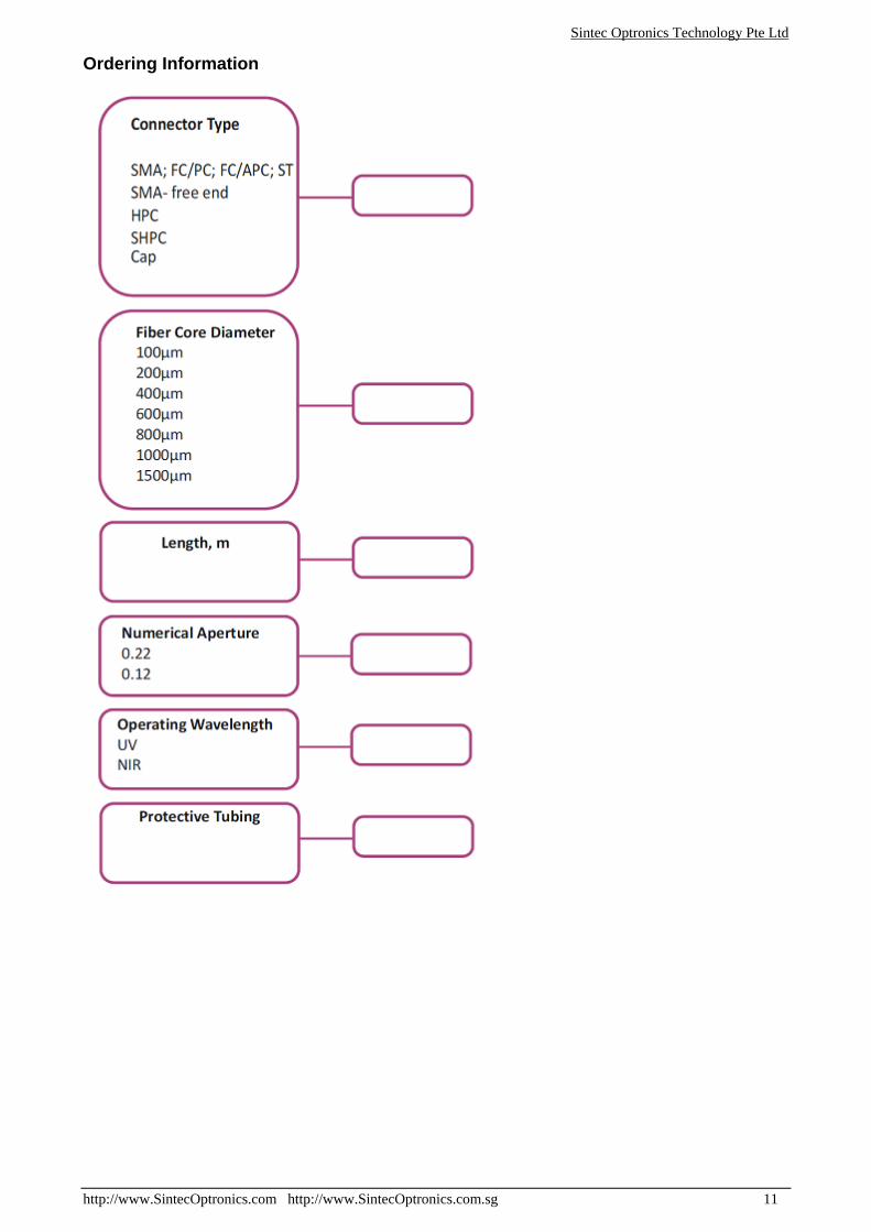
Ordering Information
Sintec Optronics Technology Pte Ltd
http://www.SintecOptronics.com http://www.SintecOptronics.com.sg 12
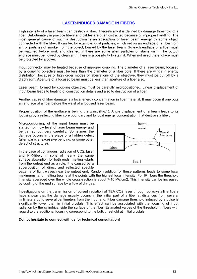
LASER-INDUCED DAMAGE IN FIBERS High intensity of a laser beam can destroy a fiber. Theoretically it is defined by damage threshold of a fiber. Unfortunately in practice fibers and cables are often distracted because of improper handling. The most general cause of such a destruction is an absorption of laser beam energy by some object connected with the fiber. It can be, for example, dust particles, which set on an endface of a fiber from air, or particles of smoke' from the object, burned by the laser beam. So each endface of a fiber must be watched before work and cleaned, if there are some alien particles or stains on it. The output endface must be flowed by clean air, if there is a possibility to stain it. When not used the endface must be protected by a cover. Input connector may be heated because of improper coupling. The diameter of a laser beam, focused by a coupling objective must be less than the diameter of a fiber core. If there are wings in energy distribution, because of high order modes or aberrations of the objective, they must be cut off by a diaphragm. Aperture of a focused beam must be less than aperture of a fiber also. Laser beam, formed by coupling objective, must be carefully micropositioned. Linear displacement of input beam leads to heating of construction details and also to destruction of a fiber. Another cause of fiber damage is a local energy concentration in fiber material. It may occur if one puts an endface of a fiber before the waist of a focused laser beam. Proper position of the endface is behind the waist (Fig.1). Angle displacement of a beam leads to its focusing by a reflecting fiber core boundary and to local energy concentration that destroys a fiber. Micropositioning, of the input beam must be started from low level of laser beam energy and be carried out very carefully. Sometimes the damage occurs in the place of a hidden defect (alien particle, excessive bending, or some other defect of structure). In the case of continuous radiation of CO2, laser and PIR-fiber, in spite of nearly the same surface absorption for both ends, melting -starts from the output end as a rule. It is caused by a superposition of direct and reflected speckle patterns of light waves near the output end. Random addition of these patterns leads to some local maximums, and melting begins at the points with the highest local intensity. For IR fibers the threshold intensity averaged over the whole cross-section is about 7-10 kW/cm2. This intensity can be increased by cooling of the end surface by a flow of dry gas. Investigations on the transmission of pulsed radiation of TEA CO2 laser through polycrystalline fibers have shown that the damage usually occurs in the initial part of a fiber at distances from several millimeters up to several centimeters from the input end. Fiber damage threshold induced by a pulse is significantly lower than in initial crystals. This effect can be associated with the focusing of input radiation by the cylindrical side the surface of the fiber. Estimated values of the threshold in fibers with regard to the additional focusing correspond to the bulk threshold at initial crystals. Do not hesitate to connect with us for technical consultation!