CH2:Intel 8086 MICROPROCESSOR ARCHITECTURE
20
CH2:Intel 8086 MICROPROCESSOR ARCHITECTURE Dr. Jamal A. Hameed COMP_ARCT1 1 Tikrit University The academic year 2019-2020 College of Petroleum Process Eng. Petroleum and Control Eng. Dept. Course:Computer Architecture1
Transcript of CH2:Intel 8086 MICROPROCESSOR ARCHITECTURE
CH2:Intel 8086 MICROPROCESSOR ARCHITECTURE
Dr. Jamal A. Hameed
COMP_ARCT1
1
Tikrit University The academic year 2019-2020
College of Petroleum Process Eng. Petroleum and Control Eng. Dept.
Course:Computer Architecture1
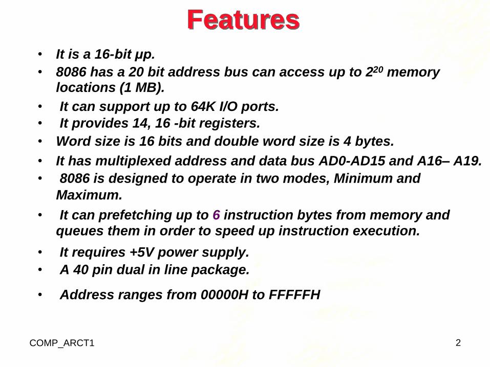
• It is a 16-bit μp.
• 8086 has a 20 bit address bus can access up to 2 20 memory
Features
locations (1 MB).
• It can support up to 64K I/O ports.
• It provides 14, 16 -bit registers.
• Word size is 16 bits and double word size is 4 bytes.
• It has multiplexed address and data bus AD0-AD15 and A16– A19.
• 8086 is designed to operate in two modes, Minimum and
Maximum.
• It can prefetching up to 6 instruction bytes from memory and queues them in order to speed up instruction execution.
• It requires +5V power supply.
• A 40 pin dual in line package.
• Address ranges from 00000H to FFFFFH
COMP_ARCT1 2
3
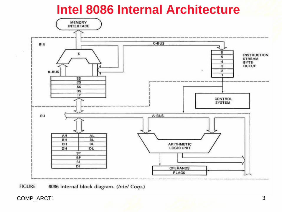
Intel 8086 Internal Architecture
COMP_ARCT1
Internal architecture of 8086
• 8086 has two blocks BIU and EU.
• The BIU handles all transactions of data and addresses on the buses for EU.
• The BIU performs all bus operations such as instruction fetching, reading and writing operands for memory and calculating the addresses of the memory operands. The
instruction bytes are transferred to the instruction queue.
• EU executes instructions from the instruction system
byte queue.
• BIU contains Instruction queue, Segment registers,
COMP_ARCT1
Instruction pointer, Address adder.
• EU contains Control circuitry, Instruction decoder, ALU,
Pointer and Index register, Flag register.
4
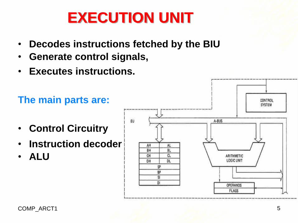
EXECUTION UNIT
• Decodes instructions fetched by the BIU
• Generate control signals,
• Executes instructions.
The main parts are:
• Control Circuitry
• Instruction decoder
• ALU
COMP_ARCT1 5
Destination Index
Source Index
Base Pointer
Stack Pointer
Data
Count
Base
Accumulator
16 bits
8 bits 8 bits
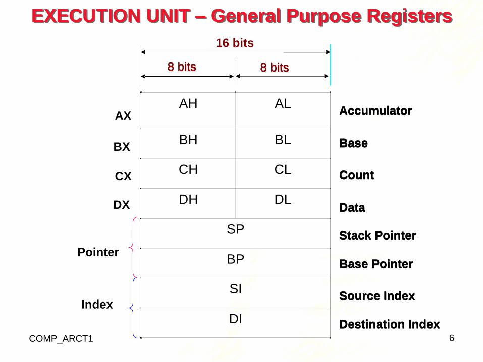
EXECUTION UNIT – General Purpose Registers
8 bits 8 bits
Accumulator
Base
Count
Data
Stack Pointer
Pointer
Base Pointer
Index Source Index
Destination Index
COMP_ARCT1 6
AH AL
BH BL
CH CL
DH DL
SP
BP
SI
DI
AX
BX
CX
DX
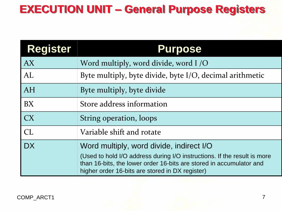
EXECUTION UNIT – General Purpose Registers
COMP_ARCT1 7
Register Purpose
AX Word multiply, word divide, word I /O
AL Byte multiply, byte divide, byte I/O, decimal arithmetic
AH Byte multiply, byte divide
BX Store address information
CX String operation, loops
CL Variable shift and rotate
DX Word multiply, word divide, indirect I/O
(Used to hold I/O address during I/O instructions. If the result is more
than 16-bits, the lower order 16-bits are stored in accumulator and
higher order 16-bits are stored in DX register)

Pointer And Index Registers
• used to keep offset addresses.
• Used in various forms of memory addressing.
• In the case of SP and BP the default reference to form a physical address is the Stack Segment (SS-will be
discussed under the BIU)
• The index registers (SI & DI) and the BX generally default to the Data segment register (DS).
SP: Stack pointer
– Used with SS to access the stack segment
BP: Base Pointer
– Primarily used to access data on the stack
– Can be used to access data in other segments
COMP_ARCT1 8
• SI: Source Index register
– is required for some string operations
– When string operations are performed, the SI register points to memory locations in the data segment which is
addressed by the DS register. Thus, SI is associated with the DS in string operations.
• DI: Destination Index register
– is also required for some string operations.
– When string operations are performed, the DI register points to memory locations in the data segment which is addressed by the ES register. Thus, DI is associated
with the ES in string operations.
• The SI and the DI registers may also be used to access data stored in arraysبييييييييييييييييييييييييييييييييييييييييييييييي
COMP_ARCT1 9
Over flow
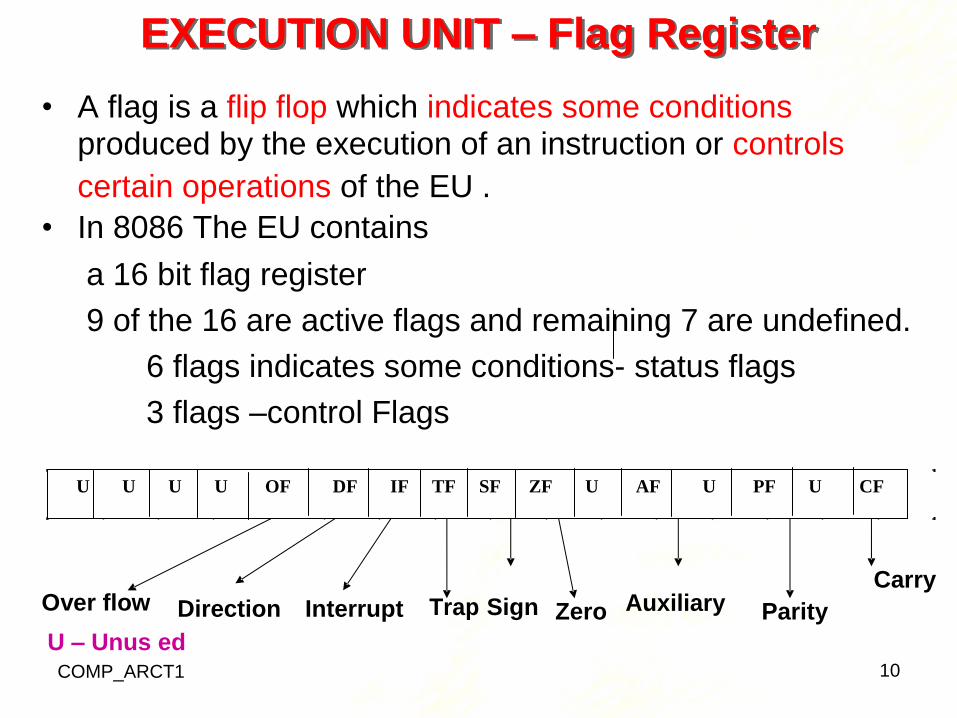
EXECUTION UNIT – Flag Register
• A flag is a flip flop which indicates some conditions produced by the execution of an instruction or controls
certain operations of the EU .
• In 8086 The EU contains
a 16 bit flag register
9 of the 16 are active flags and remaining 7 are undefined.
6 flags indicates some conditions- status flags
3 flags –control Flags
Direction Interrupt
U – Unus ed
Trap Sign Zero
Auxiliary Parity
Carry
COMP_ARCT1 10
U U U U OF DF IF TF SF ZF U AF U PF U CF
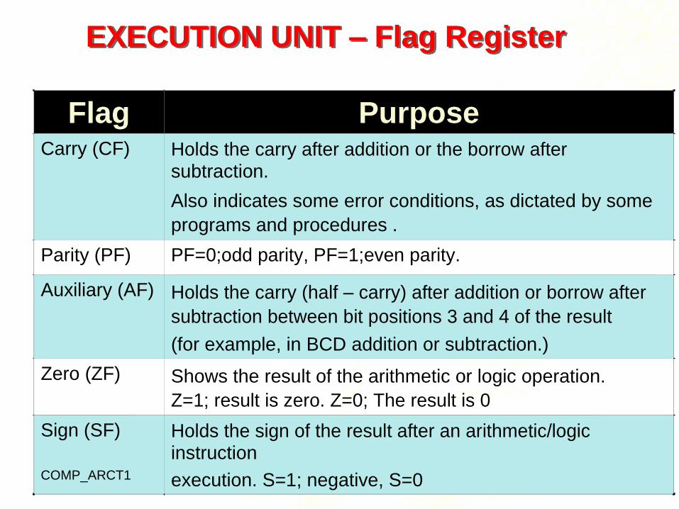
EXECUTION UNIT – Flag Register
11
Flag Purpose
Carry (CF) Holds the carry after addition or the borrow after
subtraction.
Also indicates some error conditions, as dictated by some
programs and procedures .
Parity (PF) PF=0;odd parity, PF=1;even parity.
Auxiliary (AF) Holds the carry (half – carry) after addition or borrow after
subtraction between bit positions 3 and 4 of the result
(for example, in BCD addition or subtraction.)
Zero (ZF) Shows the result of the arithmetic or logic operation.
Z=1; result is zero. Z=0; The result is 0
Sign (SF)
COMP_ARCT1
Holds the sign of the result after an arithmetic/logic
instruction
execution. S=1; negative, S=0
COMP_ARCT1 12
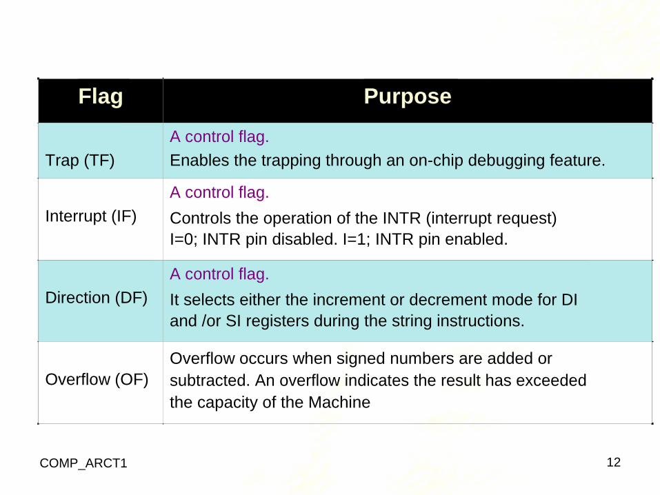
Flag Purpose
Trap (TF)
A control flag.
Enables the trapping through an on-chip debugging feature.
Interrupt (IF)
A control flag.
Controls the operation of the INTR (interrupt request)
I=0; INTR pin disabled. I=1; INTR pin enabled.
Direction (DF)
A control flag.
It selects either the increment or decrement mode for DI
and /or SI registers during the string instructions.
Overflow (OF)
Overflow occurs when signed numbers are added or
subtracted. An overflow indicates the result has exceeded
the capacity of the Machine
Execution unit – Flag Register
• Six of the flags are status indicators reflecting properties of the last arithmetic or logical instruction.
• For example, if register AL = 7Fh and the instruction ADD AL,1 is executed then the following happen
COMP_ARCT1
13
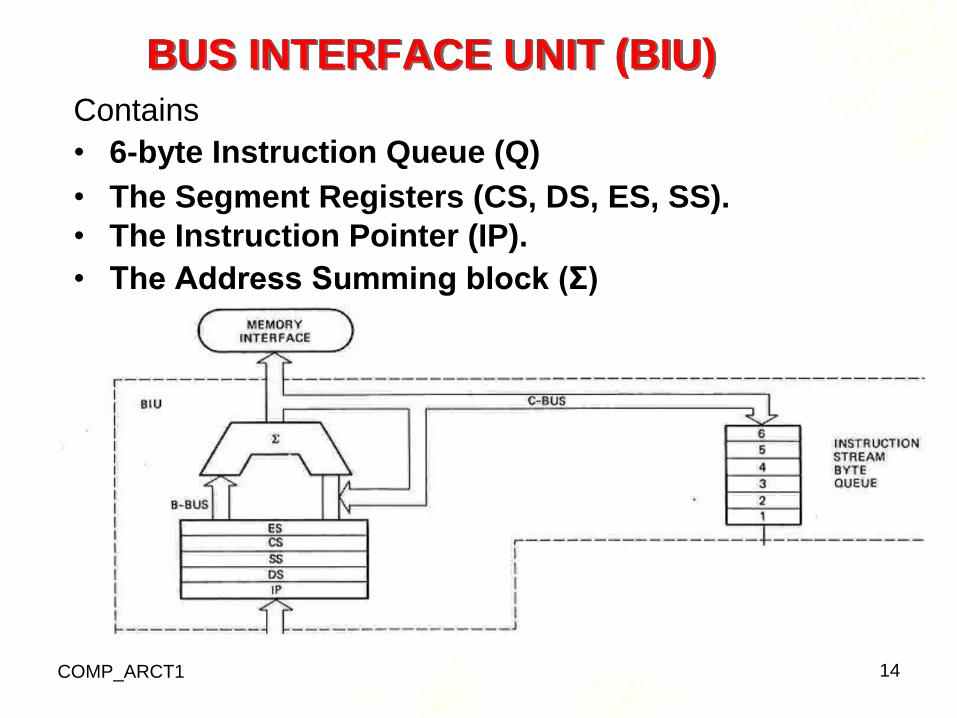
BUS INTERFACE UNIT (BIU)
Contains
• 6-byte Instruction Queue (Q)
• The Segment Registers (CS, DS, ES, SS).
• The Instruction Pointer (IP).
• The Address Summing block (Σ)
COMP_ARCT1 14
THE QUEUE (Q)
• The BIU uses a mechanism known as an instruction stream queue to implement a pipeline architecture.
• This queue permits pre-fetch of up to 6 bytes of instruction code. Whenever the queue of the BIU is not
full, it has room for at least two more bytes and at the same time the EU is not requesting it to read or write
operands from memory, the BIU is free to look ahead in the program by prefetching the next sequential
instruction.
COMP_ARCT1 15
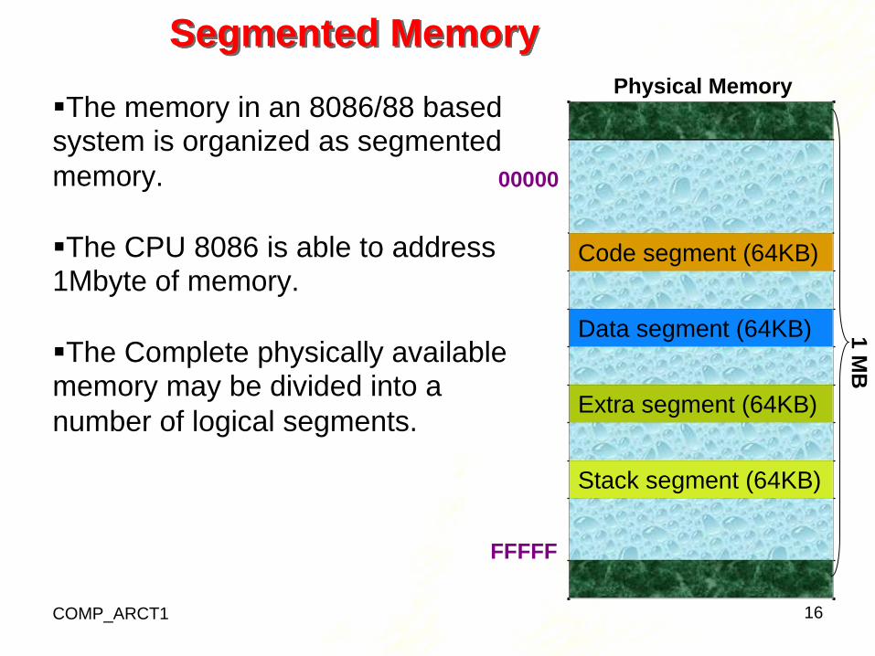
Segmented Memory
The memory in an 8086/88 based system is organized as segmented
Physical Memory
memory.
00000
The CPU 8086 is able to address 1Mbyte of memory.
The Complete physically available memory may be divided into a
number of logical segments.
FFFFF
COMP_ARCT1 16
Code segment (64KB)
Data segment (64KB)
Extra segment (64KB)
Stack segment (64KB)
1 M
B
• The size of each segment is 64 KB
• A segment may be located any where in the memory
• Each of these segments can be used for a specific
function.
– Code segment is used for storing the instructions.
– The stack segment is used as a stack and it is used to store the return addresses.
– The data and extra segments are used for storing data byte.
• The 4 segments are Code, Data, Extra and Stack segments.
• A Segment is a 64kbyte block of memory.
• The 16 bit contents of the segment registers in the BIU actually point to the starting location of a particular
segment.
• Segments may be overlapped or non-overlapped COMP_ARCT1 17
18
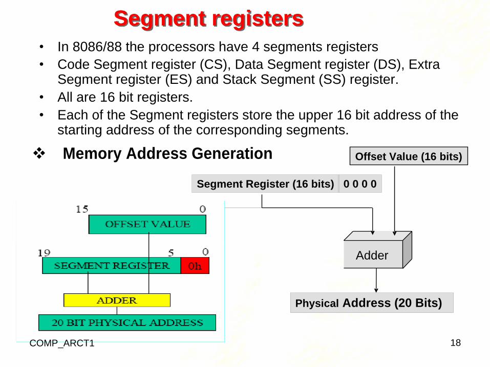
Segment Register (16 bits) 0 0 0 0
Physical Address (20 Bits)
Segment registers
• In 8086/88 the processors have 4 segments registers
• Code Segment register (CS), Data Segment register (DS), Extra Segment register (ES) and Stack Segment (SS) register.
• All are 16 bit registers.
• Each of the Segment registers store the upper 16 bit address of the starting address of the corresponding segments.
Memory Address Generation Offset Value (16 bits)
Adder
COMP_ARCT1
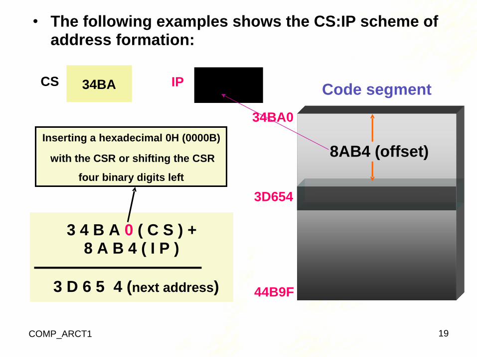
• The following examples shows the CS:IP scheme of address formation:
34BA 8AB4 Code segment
34BA0
Inserting a hexadecimal 0H (0000B)
with the CSR or shifting the CSR 8AB4 (offset)
four binary digits left
3D654
3 4 B A 0 ( C S ) + 8 A B 4 ( I P )
3 D 6 5 4 (next address) 44B9F
COMP_ARCT1 19
CS IP
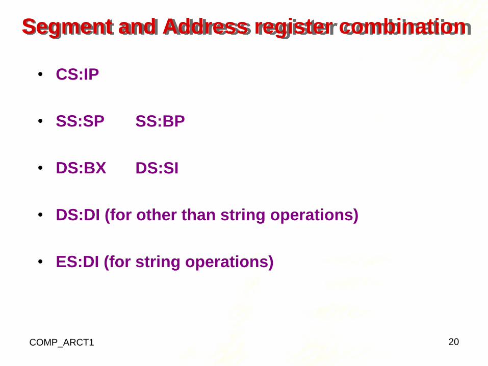
Segment and Address register combination
• CS:IP
• SS:SP
• DS:BX
SS:BP
DS:SI
• DS:DI (for other than string operations)
• ES:DI (for string operations)
COMP_ARCT1 20