CEEN 3304 T3 Flexural Analysis and Design of Beamsusers.tamuk.edu/kfgfa00/CEEN 3304/Lectures/CEEN...
25
1 Page 1 CEEN 3304 Concrete Design Flexural Analysis and Design of Beams Francisco Aguíñiga Assistant Professor Civil and Architectural Engineering Program Texas A&M University – Kingsville Page 2 Stress distributions
Transcript of CEEN 3304 T3 Flexural Analysis and Design of Beamsusers.tamuk.edu/kfgfa00/CEEN 3304/Lectures/CEEN...
1
Page 1
CEEN 3304 Concrete Design
Flexural Analysis and Design of Beams
Francisco AguíñigaAssistant Professor
Civil and Architectural Engineering ProgramTexas A&M University – Kingsville
Page 2
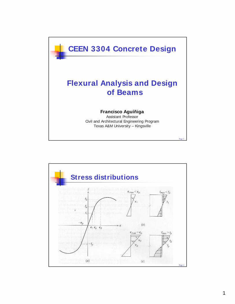
Stress distributions
2
Page 3
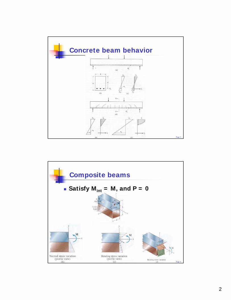
Concrete beam behavior
Page 4
Composite beams
Satisfy Mint = M, and P = 0
3
Page 5
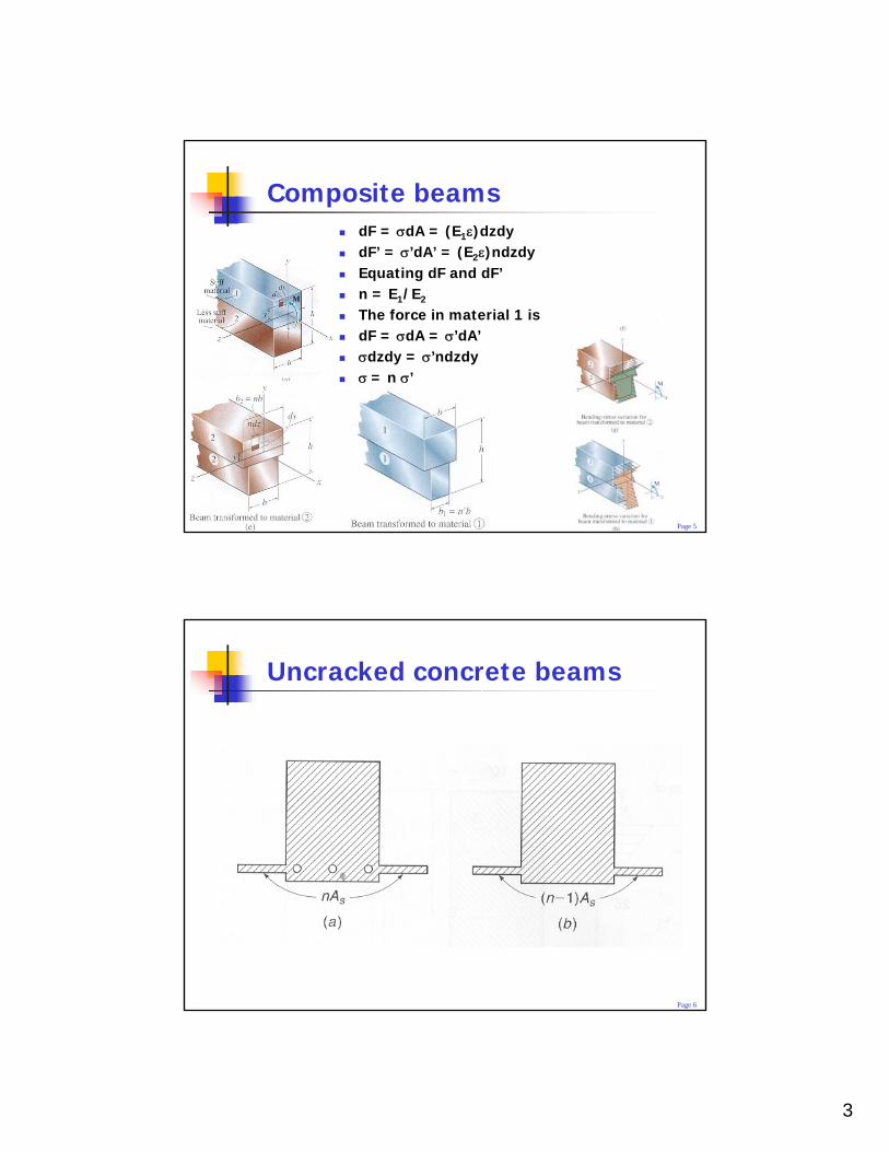
Composite beamsdF = σdA = (E1ε)dzdydF’ = σ’dA’ = (E2ε)ndzdyEquating dF and dF’n = E1/E2
The force in material 1 isdF = σdA = σ’dA’σdzdy = σ’ndzdyσ = n σ’
Page 6
Uncracked concrete beams
4
Page 7
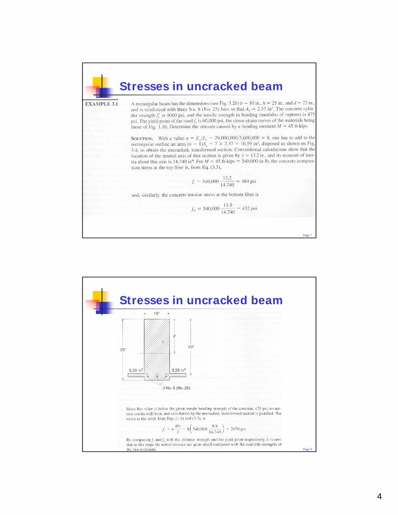
Stresses in uncracked beam
Page 8
Stresses in uncracked beam
5
Page 9
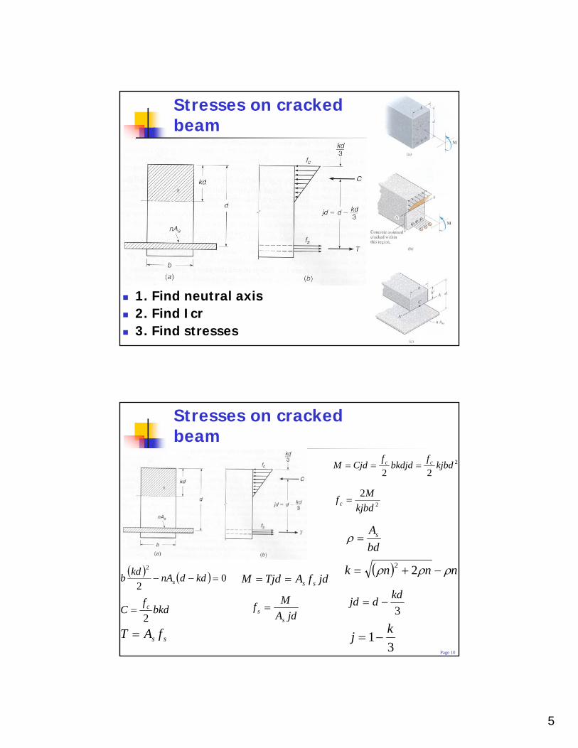
Stresses on cracked beam
1. Find neutral axis2. Find Icr3. Find stresses
Page 10
Stresses on cracked beam
( ) ( ) 02
2
=−− kddnAkdb s
bkdf
C c
2=
ss fAT =
jdfATjdM ss==
jdAMfs
s =
2
22kjbd
fbkdjd
fCjdM cc ===
2
2kjbd
Mfc =
bdAs=ρ
( ) nnnk ρρρ −+= 22
3kddjd −=
31 kj −=
6
Page 11
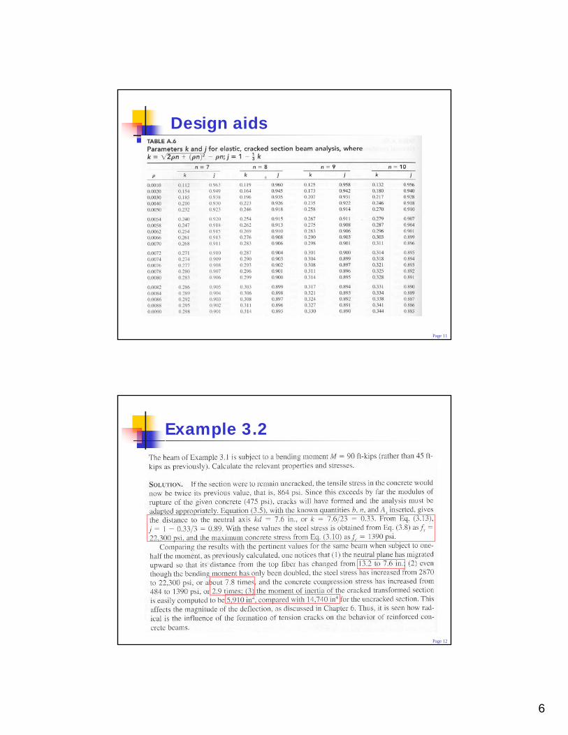
Design aids
Page 12
Example 3.2
7
Page 13
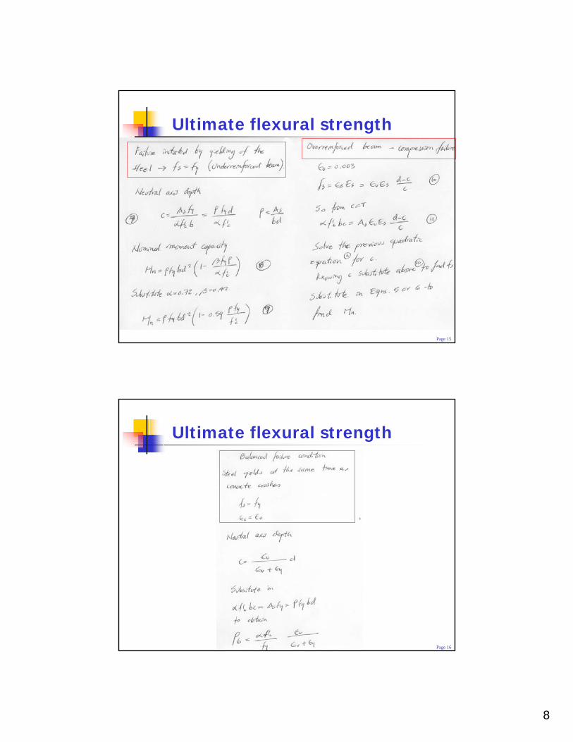
Ultimate flexural strength
Steel fails when fs = fy
Concrete fails when εc = εu = 0.003Knowing c need to know: C and β
Page 14
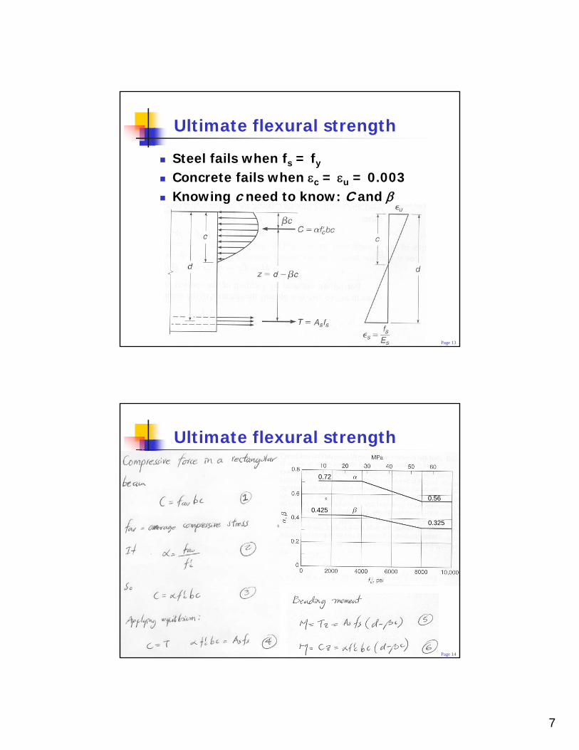
Ultimate flexural strength
0.72
0.425
0.325
0.56
8
Page 15
Ultimate flexural strength
Page 16
Ultimate flexural strength
9
Page 17
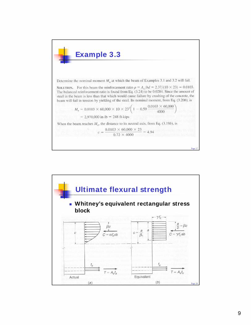
Example 3.3
Page 18
Ultimate flexural strength
Whitney’s equivalent rectangular stress block
10
Page 19
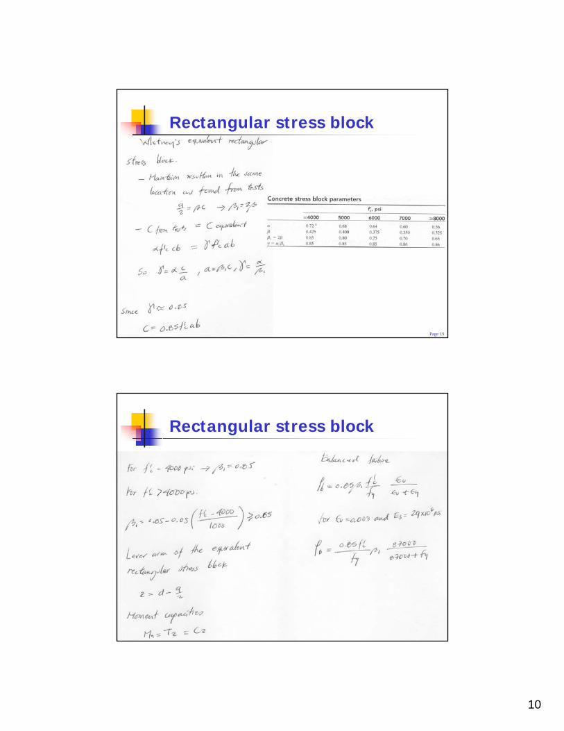
Rectangular stress block
Page 20
Rectangular stress block
11
Page 21
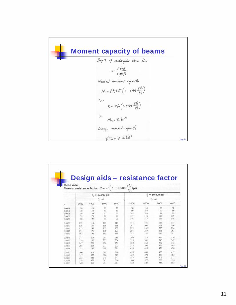
Moment capacity of beams
Page 22
Design aids – resistance factor
12
Page 23
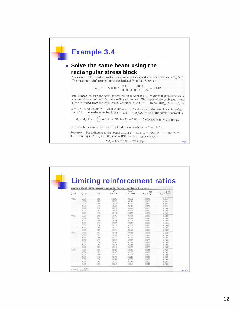
Example 3.4
Solve the same beam using the rectangular stress block
Page 24
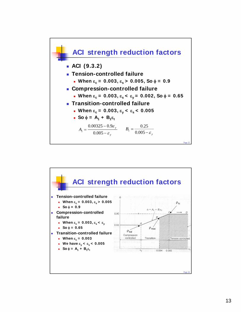
Limiting reinforcement ratios
13
Page 25
ACI strength reduction factors
ACI (9.3.2)Tension-controlled failure
When εc = 0.003, εs > 0.005, So φ = 0.9
Compression-controlled failureWhen εc = 0.003, εs < εy = 0.002, So φ = 0.65
Transition-controlled failureWhen εc = 0.003, εy < εs < 0.005So φ = A1 + B1εt
y
yAε
ε−
−=
005.09.000325.0
1y
Bε−
=005.0
25.01
Page 26
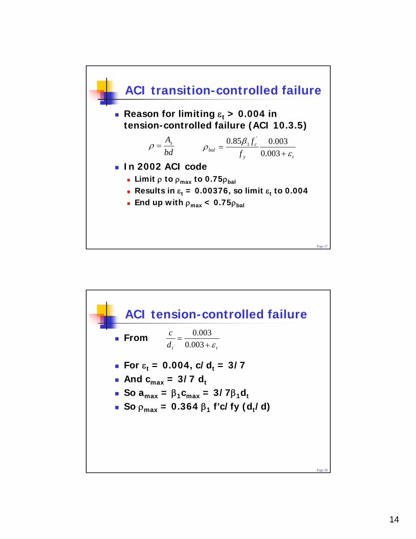
ACI strength reduction factors
Tension-controlled failureWhen εc = 0.003, εs > 0.005So φ = 0.9
Compression-controlled failure
When εc = 0.003, εs < εy
So φ = 0.65Transition-controlled failure
When εc = 0.003We have εy < εs < 0.005So φ = A1 + B1εt
ρmax
ρtc
ρbal
14
Page 27
ACI transition-controlled failure
Reason for limiting εt > 0.004 in tension-controlled failure (ACI 10.3.5)
In 2002 ACI codeLimit ρ to ρmax to 0.75ρbal
Results in εt = 0.00376, so limit εt to 0.004End up with ρmax < 0.75ρbal
bdAs=ρ
ty
cbal f
fε
βρ
+=
003.0003.085.0 '
1
Page 28
ACI tension-controlled failure
From
For εt = 0.004, c/dt = 3/7And cmax = 3/7 dt
So amax = β1cmax = 3/7β1dt
So ρmax = 0.364 β1 f’c/fy (dt/d)
ttdc
ε+=
003.0003.0
15
Page 29
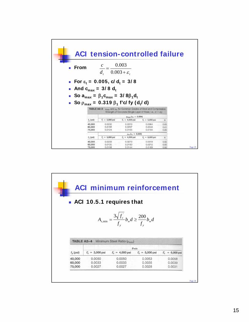
ACI tension-controlled failure
From
For εt = 0.005, c/dt = 3/8And cmax = 3/8 dt
So amax = β1cmax = 3/8β1dt
So ρmax = 0.319 β1 f’c/fy (dt/d)
ttdc
ε+=
003.0003.0
Page 30
ACI minimum reinforcement
ACI 10.5.1 requires that
dbf
dbff
A wy
wy
cs
2003 '
min, ≥=
16
Page 31
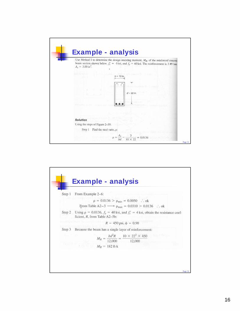
Example - analysis
Page 32
Example - analysis
17
Page 33
Design of R/C beams
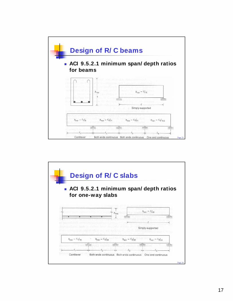
ACI 9.5.2.1 minimum span/depth ratios for beams
Page 34
Design of R/C slabs
ACI 9.5.2.1 minimum span/depth ratios for one-way slabs
18
Page 35
Design of R/C beams
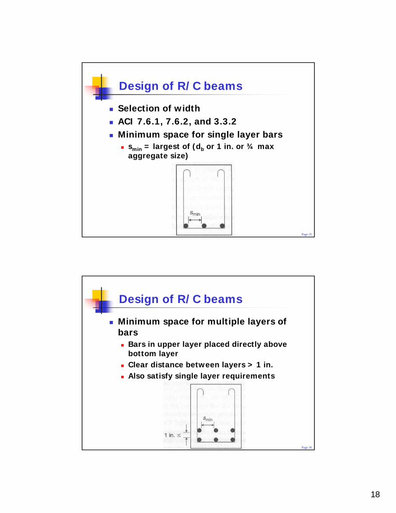
Selection of widthACI 7.6.1, 7.6.2, and 3.3.2Minimum space for single layer bars
smin = largest of (db or 1 in. or ¾ max aggregate size)
Page 36
Design of R/C beams
Minimum space for multiple layers of bars
Bars in upper layer placed directly above bottom layerClear distance between layers > 1 in.Also satisfy single layer requirements
19
Page 37
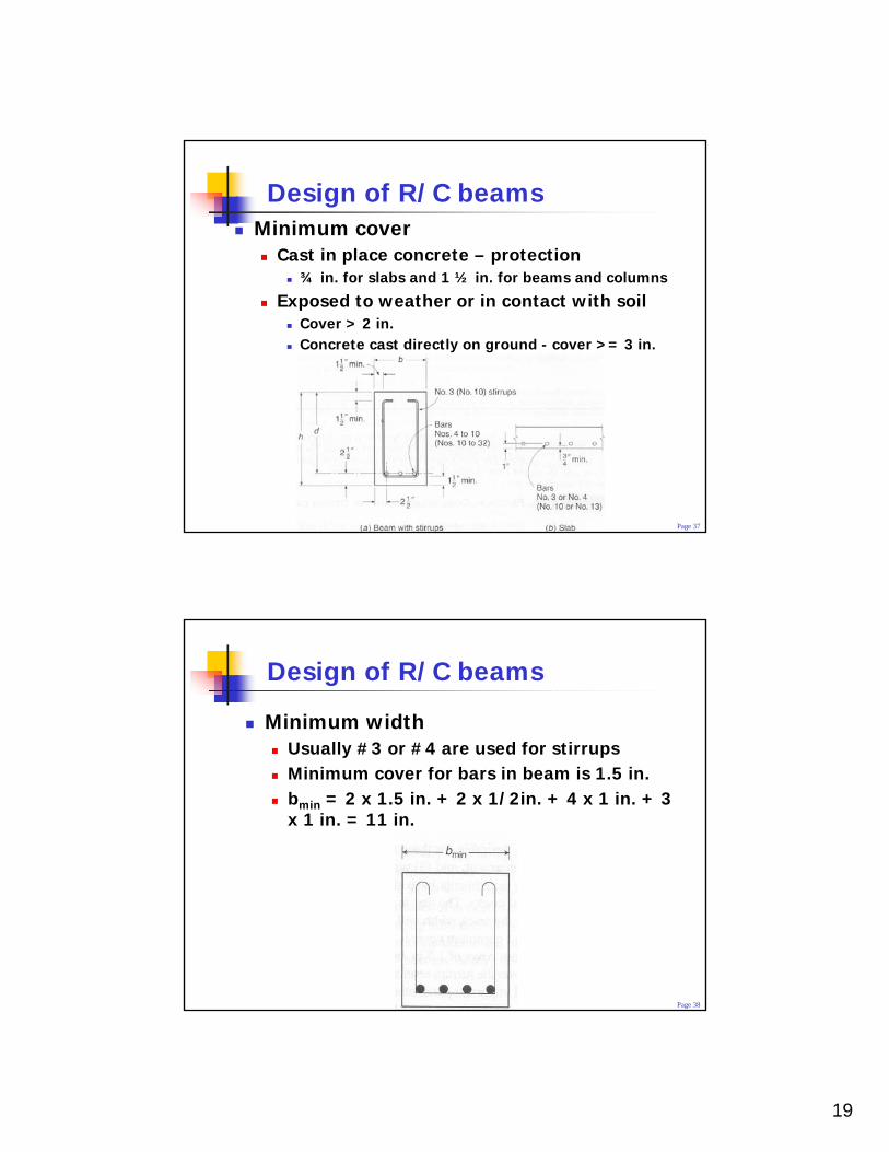
Design of R/C beamsMinimum cover
Cast in place concrete – protection¾ in. for slabs and 1 ½ in. for beams and columns
Exposed to weather or in contact with soilCover > 2 in.Concrete cast directly on ground - cover >= 3 in.
Page 38
Design of R/C beams
Minimum widthUsually #3 or #4 are used for stirrupsMinimum cover for bars in beam is 1.5 in.bmin = 2 x 1.5 in. + 2 x 1/2in. + 4 x 1 in. + 3 x 1 in. = 11 in.
20
Page 39
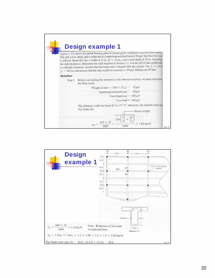
Design example 1
Page 40
Design example 1
21
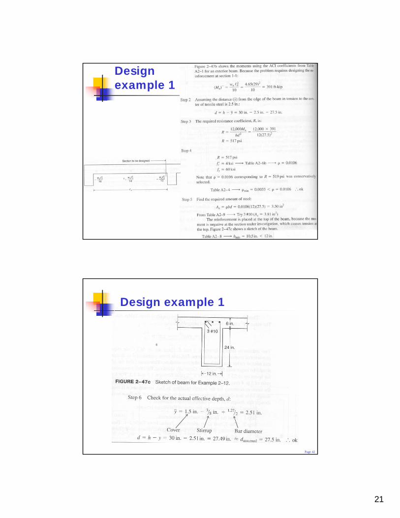
Page 41
Design example 1
Page 42
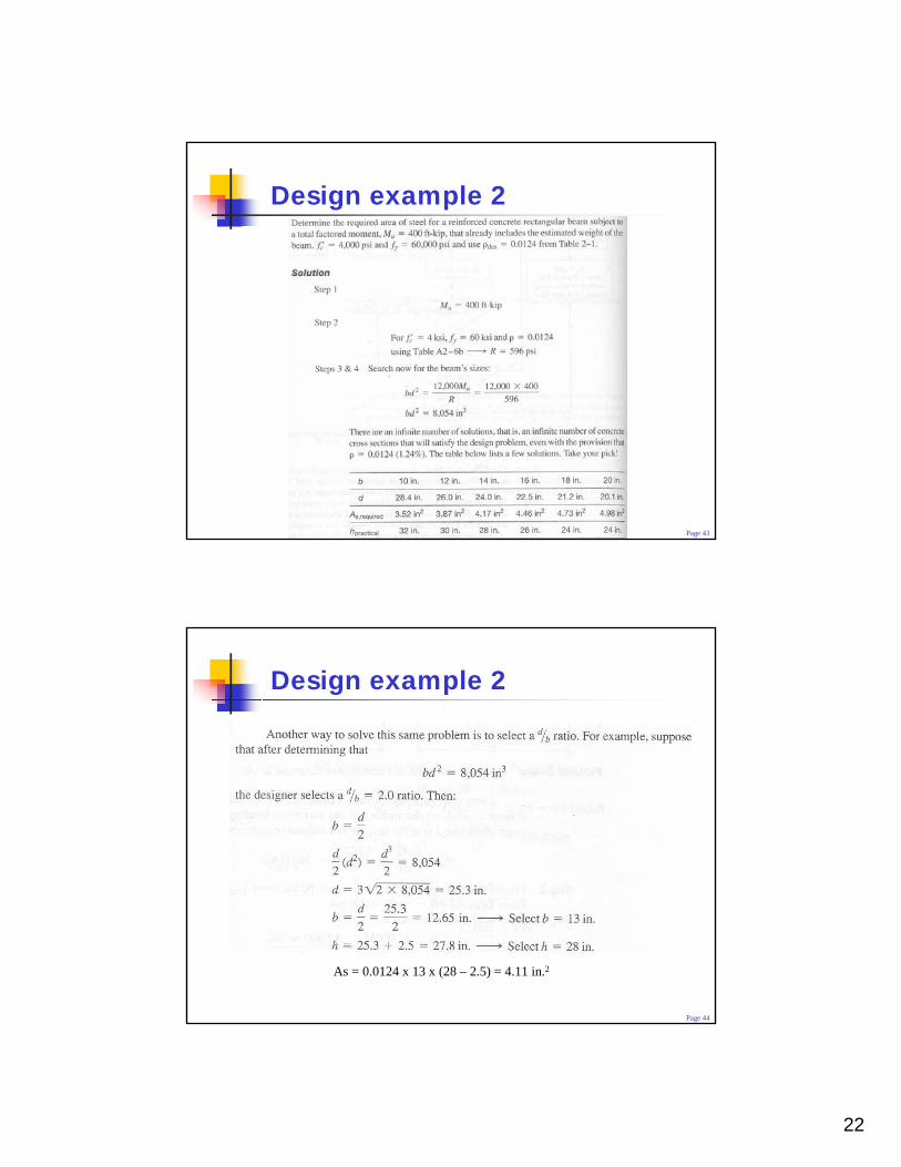
Design example 1
22
Page 43
Design example 2
Page 44
Design example 2
As = 0.0124 x 13 x (28 – 2.5) = 4.11 in.2
23
Page 45
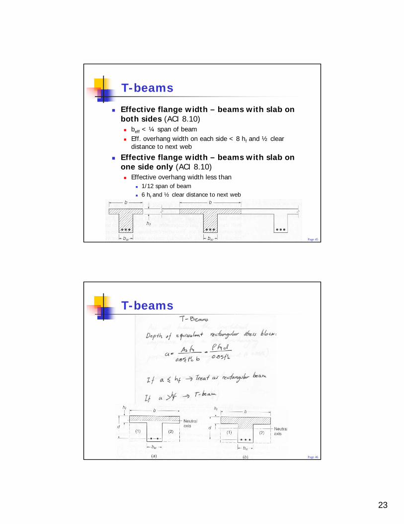
T-beams
Effective flange width – beams with slab on both sides (ACI 8.10)
beff < ¼ span of beamEff. overhang width on each side < 8 hf and ½ clear distance to next web
Effective flange width – beams with slab on one side only (ACI 8.10)
Effective overhang width less than1/12 span of beam6 hf and ½ clear distance to next web
Page 46
T-beams
24
Page 47
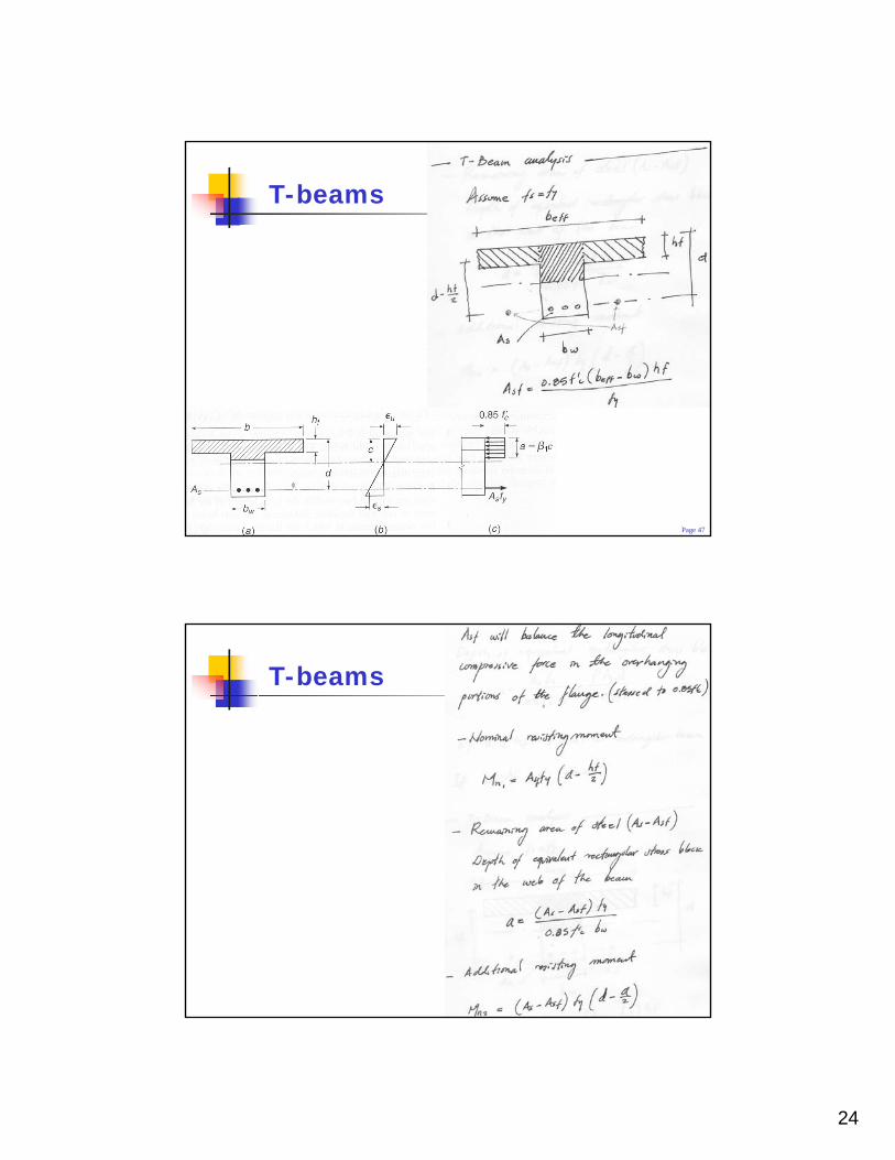
T-beams
Page 48
T-beams
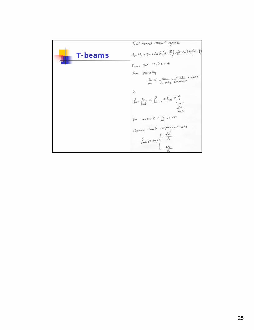
25
Page 49
T-beams