CE 303 homework probs - Adnan Menderes University · 6 (d) COMPRESSIBILITY AND CONSOLIDATION D1. A...
12
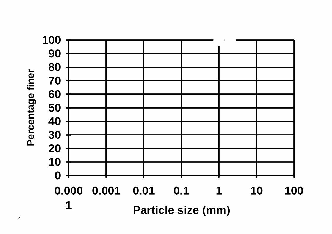
1 Adnan Menderes University Department of Civil Engineering CE 303 - Soil Mechanics PROBLEMS NOTE. Unless otherwise stated, take γ w = 10 kN/m 3 (a) BASIC PROPERTIES A1. A cubic meter of soil in its natural state weighs 17.75 kN; after being dried it weighs 15.08 kN. The specific gravity of the solids is 2.70. (a) Determine the water content, void ratio, porosity and degree of saturation for the soil as it existed in its natural state. (b) What would be the bulk unit weight and water content if the soil were fully saturated at the same void ratio as in its natural state ? A2. A sand with a minimum void ratio of 0.45 and a maximum void ratio of 0.97 has a relative density of 40 %. How much will a 3 m thick stratum of this sand settle if the sand is densified to a relative density of 65 %? Assume that the sand layer is compressed in the vertical direction only, with no lateral strain. A3. The results of sieve analysis on a soil sample are given below: Sieve size Percentage finer 19.1 mm 100 6.3 mm 94 2 mm 69 590 μm 32 210 μm 13 74 μm 2 (a) Plot the grain size distribution curve on the chart provided, marking the intermediate graduations. (b) Determine the percentages of gravel, sand and the fines in the sample. (c) Determine D 10 , D 30 , D 60 , C u , C c and comment on the gradation. A.4. The consistency limits for a given clay were determined to be LL = 55%, PL = 27%, SL = 20% (a) If the specific gravity of solid particles is 2.70, and a 100 cm 3 saturated sample of this soil at its natural water content of 30% is allowed to dry, what will be its volume at a water content of 15%? (b) What is the consistency of the soil in its natural state ? (c) Calculate the plasticity index of the soil. (d) Determine the liquidity index of the soil.
Transcript of CE 303 homework probs - Adnan Menderes University · 6 (d) COMPRESSIBILITY AND CONSOLIDATION D1. A...
1
Adnan Menderes University Department of Civil Engineering
CE 303 - Soil Mechanics PROBLEMS
NOTE. Unless otherwise stated, take γw = 10 kN/m3 (a) BASIC PROPERTIES A1. A cubic meter of soil in its natural state weighs 17.75 kN; after being dried it weighs 15.08 kN. The specific gravity of the solids is 2.70. (a) Determine the water content, void ratio, porosity and degree of saturation for the soil as it existed in its natural state. (b) What would be the bulk unit weight and water content if the soil were fully saturated at the same void ratio as in its natural state ? A2. A sand with a minimum void ratio of 0.45 and a maximum void ratio of 0.97 has a relative density of 40 %. How much will a 3 m thick stratum of this sand settle if the sand is densified to a relative density of 65 %? Assume that the sand layer is compressed in the vertical direction only, with no lateral strain. A3. The results of sieve analysis on a soil sample are given below: Sieve size Percentage finer 19.1 mm 100 6.3 mm 94 2 mm 69 590 μm 32 210 μm 13 74 μm 2 (a) Plot the grain size distribution curve on the chart provided, marking the intermediate graduations. (b) Determine the percentages of gravel, sand and the fines in the sample. (c) Determine D10, D30, D60, Cu, Cc and comment on the gradation. A.4. The consistency limits for a given clay were determined to be LL = 55%, PL = 27%, SL = 20% (a) If the specific gravity of solid particles is 2.70, and a 100 cm3 saturated sample of this soil at its natural water content of 30% is allowed to dry, what will be its volume at a water content of 15%? (b) What is the consistency of the soil in its natural state ? (c) Calculate the plasticity index of the soil. (d) Determine the liquidity index of the soil.
2Particle size (mm)
Perc
enta
ge fi
ner
0102030405060708090
100
0.0001
0.001 0.01 0.1 1 10 100

3
4
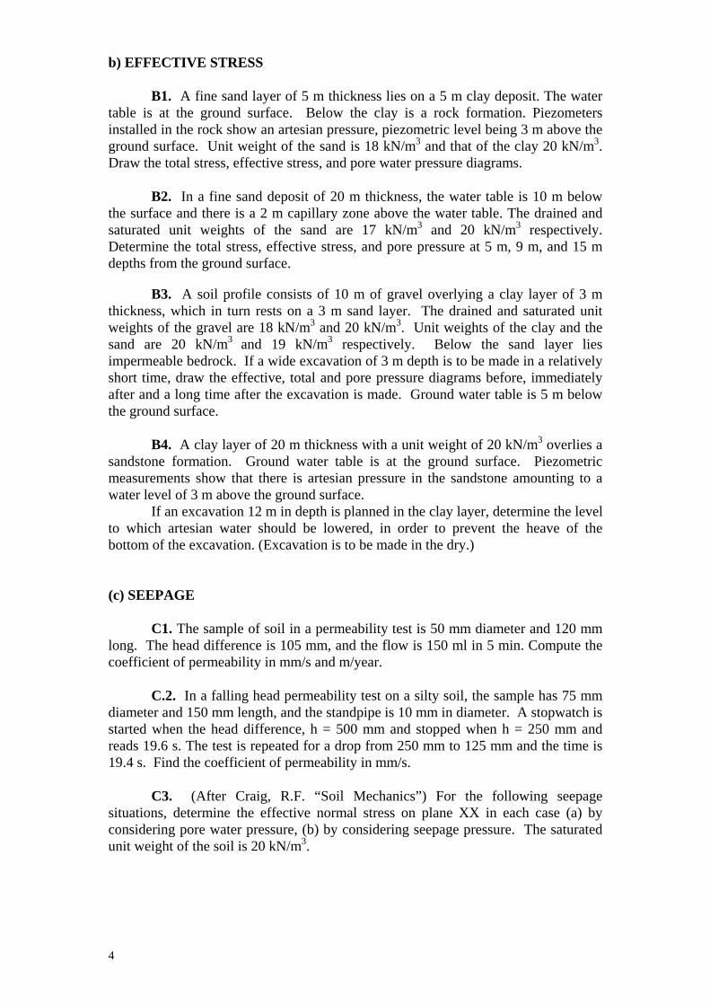
b) EFFECTIVE STRESS B1. A fine sand layer of 5 m thickness lies on a 5 m clay deposit. The water table is at the ground surface. Below the clay is a rock formation. Piezometers installed in the rock show an artesian pressure, piezometric level being 3 m above the ground surface. Unit weight of the sand is 18 kN/m3 and that of the clay 20 kN/m3. Draw the total stress, effective stress, and pore water pressure diagrams. B2. In a fine sand deposit of 20 m thickness, the water table is 10 m below the surface and there is a 2 m capillary zone above the water table. The drained and saturated unit weights of the sand are 17 kN/m3 and 20 kN/m3 respectively. Determine the total stress, effective stress, and pore pressure at 5 m, 9 m, and 15 m depths from the ground surface. B3. A soil profile consists of 10 m of gravel overlying a clay layer of 3 m thickness, which in turn rests on a 3 m sand layer. The drained and saturated unit weights of the gravel are 18 kN/m3 and 20 kN/m3. Unit weights of the clay and the sand are 20 kN/m3 and 19 kN/m3 respectively. Below the sand layer lies impermeable bedrock. If a wide excavation of 3 m depth is to be made in a relatively short time, draw the effective, total and pore pressure diagrams before, immediately after and a long time after the excavation is made. Ground water table is 5 m below the ground surface. B4. A clay layer of 20 m thickness with a unit weight of 20 kN/m3 overlies a sandstone formation. Ground water table is at the ground surface. Piezometric measurements show that there is artesian pressure in the sandstone amounting to a water level of 3 m above the ground surface. If an excavation 12 m in depth is planned in the clay layer, determine the level to which artesian water should be lowered, in order to prevent the heave of the bottom of the excavation. (Excavation is to be made in the dry.) (c) SEEPAGE C1. The sample of soil in a permeability test is 50 mm diameter and 120 mm long. The head difference is 105 mm, and the flow is 150 ml in 5 min. Compute the coefficient of permeability in mm/s and m/year. C.2. In a falling head permeability test on a silty soil, the sample has 75 mm diameter and 150 mm length, and the standpipe is 10 mm in diameter. A stopwatch is started when the head difference, h = 500 mm and stopped when h = 250 mm and reads 19.6 s. The test is repeated for a drop from 250 mm to 125 mm and the time is 19.4 s. Find the coefficient of permeability in mm/s. C3. (After Craig, R.F. “Soil Mechanics”) For the following seepage situations, determine the effective normal stress on plane XX in each case (a) by considering pore water pressure, (b) by considering seepage pressure. The saturated unit weight of the soil is 20 kN/m3.
5
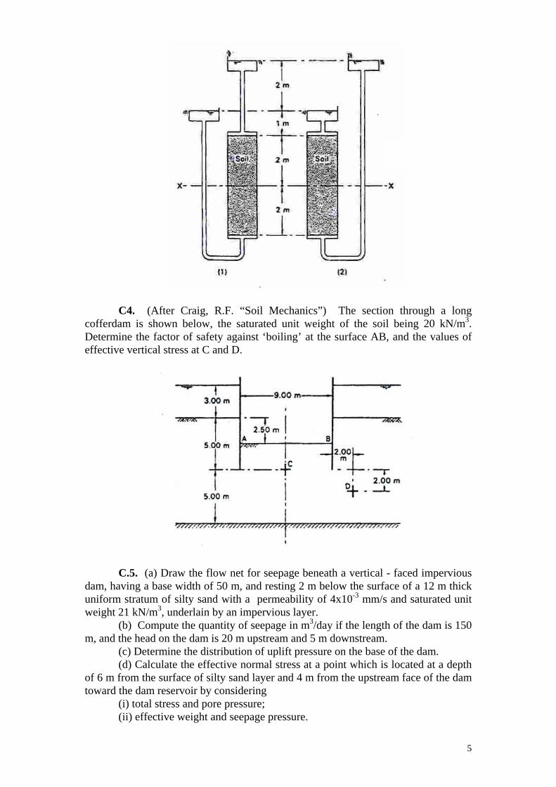
C4. (After Craig, R.F. “Soil Mechanics”) The section through a long cofferdam is shown below, the saturated unit weight of the soil being 20 kN/m3. Determine the factor of safety against ‘boiling’ at the surface AB, and the values of effective vertical stress at C and D.
C.5. (a) Draw the flow net for seepage beneath a vertical - faced impervious dam, having a base width of 50 m, and resting 2 m below the surface of a 12 m thick uniform stratum of silty sand with a permeability of 4x10⁻³ mm/s and saturated unit weight 21 kN/m3, underlain by an impervious layer. (b) Compute the quantity of seepage in m3/day if the length of the dam is 150 m, and the head on the dam is 20 m upstream and 5 m downstream. (c) Determine the distribution of uplift pressure on the base of the dam. (d) Calculate the effective normal stress at a point which is located at a depth of 6 m from the surface of silty sand layer and 4 m from the upstream face of the dam toward the dam reservoir by considering (i) total stress and pore pressure; (ii) effective weight and seepage pressure.
6
(d) COMPRESSIBILITY AND CONSOLIDATION D1. A normally consolidated clay has the following void ratio e versus effective stress σ′ relationship obtained in an oedometer test. (a) Plot the e - σ′ curve.
(b) Plot the e - log σ′ relationship and calculate the compression index.
Effective Stress σ′ (kN/m2) : 50 100 150 200 300 Void ratio, e : 0.97 0.91 0.85 0.81 0.75 D2. A 6-m deep layer of sand overlies a 4m thick clay layer. The clay layer is underlain by sandy gravel. The water table is at the ground surface and the saturated unit weight for both the sand and the clay is 19 kN/m3. A 3-m thick layer of fill (unit weight 20 kN/m3) is to be placed rapidly on the surface over an extensive area. Assume that the data given in Problem 1 corresponds to that of a representative sample from the clay, whose coefficient of consolidation is 2.4 m2/year. (a) Calculate the total and effective vertical stresses and the pore water pressure at the centre of the clay layer before the fill is placed, immediately after the fill is placed, and after the clay has consolidated under the vertical stress increment due to the fill. (b) Without subdividing the clay layer, calculate the final consolidation settlement due to the placement of the fill using (i)
Δ ΔHH
ee0 01
=+
;
(ii) coefficient of volume compressibility; (iii) compression index. (c) What is the degree of consolidation Uz at the centre of the clay layer when the pore water pressure at that depth is equal to 125 kN/m2? What is the effective stress at that depth at that time? (d) How long will it take to reach 50 % average degree of consolidation U? (e) What is the settlement at the end of 20 months? (f) What time is required for 40 mm settlement?
7
(e) SHEAR STRENGTH (For this section, take g = 9.81 m/s2) E1. Samples of compacted clean dry sand were tested in a 63 mm dia. shear box, and the following results obtained. Normal load (kgf) : 16 32 48 Peak shear load (N) : 133.4 287.4 417.7 Ultimate shear load (N) : 85.7 190.1 268.1 Determine the angle of shearing resistance of the sand (a) in the dense, and (b) in the loose state. E2. In a mixed series of unconsolidated - undrained and consolidated - undrained triaxial tests with pore pressure measurement on the unsaturated, stiff, fissured Ankara Clay (average degree of saturation = 97 %), the following results have been obtained at failure. Test no. 1 2 3 4 5 6 Pore pressure (kPa) -17 75 -17 -14 -2 -5 Cell pressure (kPa) 53 220 81 178 158 201 Deviator stress (σ1− σ3) (kPa)
234 210 374 378 450 462
Determine the shear strength parameters in terms of effective stress (a) by drawing the average tangent to the Mohr circles; (b) by calculation from the modified shear strength envelope. State which method is preferable for such variable test results, and why. E3. (a) By considering the torque on the curved (cylindrical) surface, and integrating the torque on ring-shaped elements on the two circular ends (neglecting the presence of the vane rod) of the sheared cylinder of soil, derive the following equation for the torque T required to shear a soft, saturated clay of shear strength cu, using a vane with rectangular blades of height h and diameter of circumscribing circle d.
T cd h d
u= +⎛
⎝⎜
⎞
⎠⎟π
2 3
2 6
(b) A vane 75 mm in diameter and 150 mm long was used to measure the undrained shear strength of a soft clay. A torque of 50 Nm was required to shear the soil. The vane was then rotated rapidly to remould the soil completely. The ultimate torque recorded was 19 Nm. Determine the undrained shear strength of the clay in the natural and remoulded states, and hence find the sensitivity of the clay. (c) If a 36 mm dia. undistributed specimen of the same clay as in Part (b) were tested in an unconfined compression test, what would be the axial load at failure, if the initial height is 72 mm and the specimen fails at an axial strain of 18 % ? E4. If a cylindrical specimen of saturated clay of initial height h0 and initial cross-sectional area A0 is subjected to an axial load under undrained conditions(either in the unconfined compression or in the triaxial compression test), it will undergo an axial shortening δh and its average cross-sectional area will increase to A, but its
8
volume will remain unchanged. By equating the initial volume of the specimen to its intermediate volume, prove the relationship
A Aoa
=−
⎛
⎝⎜
⎞
⎠⎟
11 ε
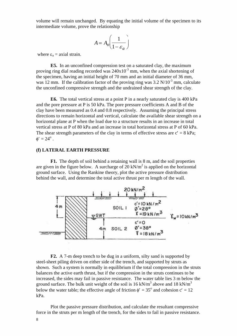
where εa = axial strain. E5. In an unconfined compression test on a saturated clay, the maximum proving ring dial reading recorded was 240x10-3 mm, when the axial shortening of the specimen, having an initial height of 70 mm and an initial diameter of 36 mm, was 12 mm. If the calibration factor of the proving ring was 3.2 N/10-3 mm, calculate the unconfined compressive strength and the undrained shear strength of the clay. E6. The total vertical stress at a point P in a nearly saturated clay is 400 kPa and the pore pressure at P is 50 kPa. The pore pressure coefficients A and B of the clay have been measured as 0.4 and 0.8 respectively. Assuming the principal stress directions to remain horizontal and vertical, calculate the available shear strength on a horizontal plane at P when the load due to a structure results in an increase in total vertical stress at P of 80 kPa and an increase in total horizontal stress at P of 60 kPa. The shear strength parameters of the clay in terms of effective stress are c′ = 8 kPa; φ′ = 24o . (f) LATERAL EARTH PRESSURE F1. The depth of soil behind a retaining wall is 8 m, and the soil properties are given in the figure below. A surcharge of 20 kN/m2 is applied on the horizontal ground surface. Using the Rankine theory, plot the active pressure distribution behind the wall, and determine the total active thrust per m length of the wall.
F2. A 7-m deep trench to be dug in a uniform, silty sand is supported by steel-sheet piling driven on either side of the trench, and supported by struts as shown. Such a system is normally in equilibrium if the total compression in the struts balances the active earth thrust, but if the compression in the struts continues to be increased, the sides may fail in passive resistance. The water table lies 3 m below the ground surface. The bulk unit weight of the soil is 16 kN/m3 above and 18 kN/m3 below the water table; the effective angle of friction φ′ = 35o and cohesion c′ = 12 kPa. Plot the passive pressure distribution, and calculate the resultant compressive force in the struts per m length of the trench, for the sides to fail in passive resistance.
9
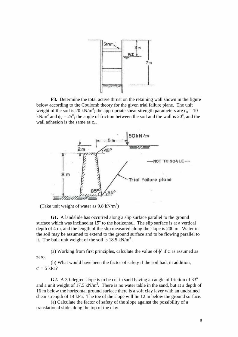
F3. Determine the total active thrust on the retaining wall shown in the figure below according to the Coulomb theory for the given trial failure plane. The unit weight of the soil is 20 kN/m3; the appropriate shear strength parameters are cu = 10 kN/m2 and φu = 25o; the angle of friction between the soil and the wall is 20o, and the wall adhesion is the same as cu. (Take unit weight of water as 9.8 kN/m3) G1. A landslide has occurred along a slip surface parallel to the ground surface which was inclined at 15o to the horizontal. The slip surface is at a vertical depth of 4 m, and the length of the slip measured along the slope is 200 m. Water in the soil may be assumed to extend to the ground surface and to be flowing parallel to it. The bulk unit weight of the soil is 18.5 kN/m3 . (a) Working from first principles, calculate the value of φ′ if c′ is assumed as zero. (b) What would have been the factor of safety if the soil had, in addition, c′ = 5 kPa? G2. A 30-degree slope is to be cut in sand having an angle of friction of 33o and a unit weight of 17.5 kN/m3. There is no water table in the sand, but at a depth of 16 m below the horizontal ground surface there is a soft clay layer with an undrained shear strength of 14 kPa. The toe of the slope will lie 12 m below the ground surface. (a) Calculate the factor of safety of the slope against the possibility of a translational slide along the top of the clay.
10
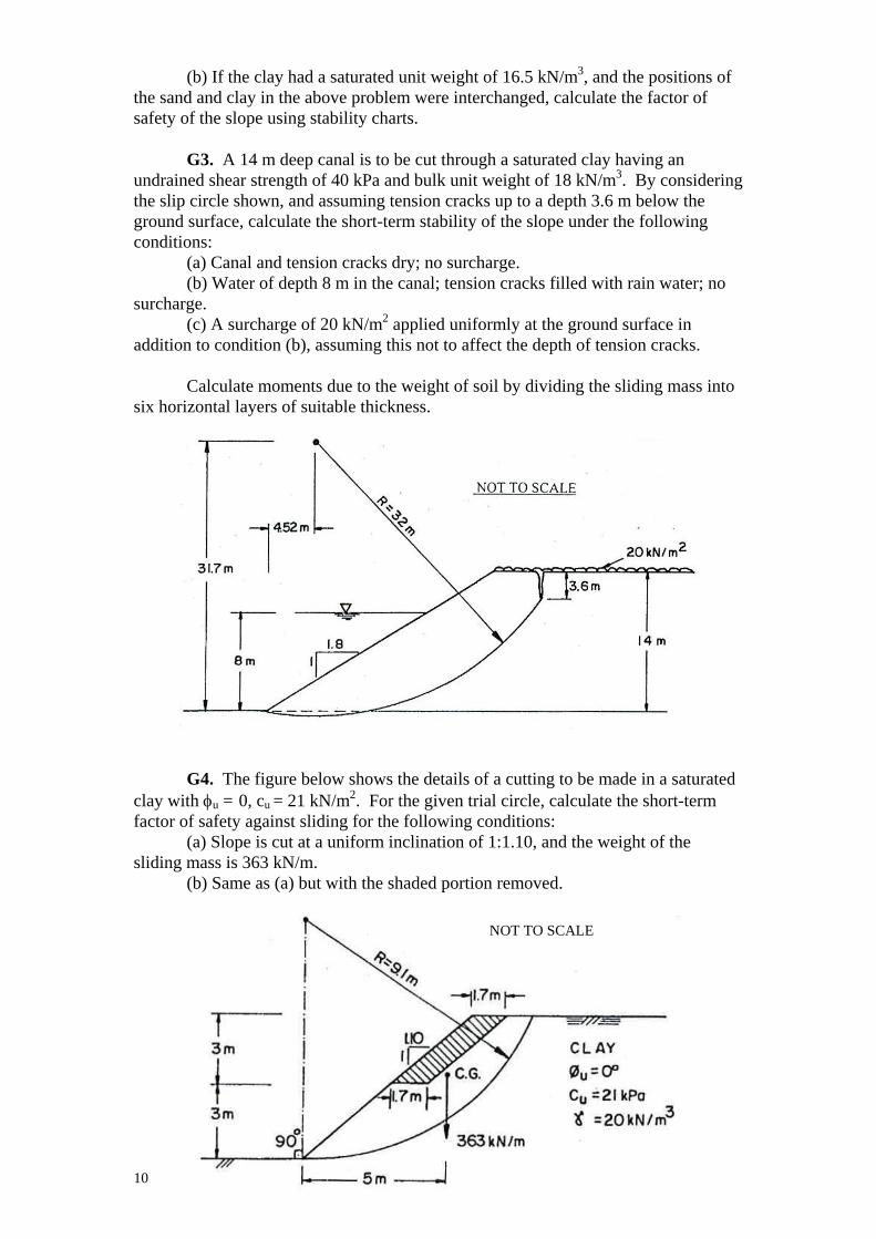
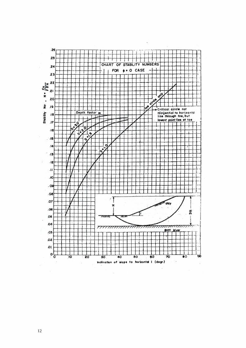
(b) If the clay had a saturated unit weight of 16.5 kN/m3, and the positions of the sand and clay in the above problem were interchanged, calculate the factor of safety of the slope using stability charts. G3. A 14 m deep canal is to be cut through a saturated clay having an undrained shear strength of 40 kPa and bulk unit weight of 18 kN/m3. By considering the slip circle shown, and assuming tension cracks up to a depth 3.6 m below the ground surface, calculate the short-term stability of the slope under the following conditions: (a) Canal and tension cracks dry; no surcharge. (b) Water of depth 8 m in the canal; tension cracks filled with rain water; no surcharge. (c) A surcharge of 20 kN/m2 applied uniformly at the ground surface in addition to condition (b), assuming this not to affect the depth of tension cracks. Calculate moments due to the weight of soil by dividing the sliding mass into six horizontal layers of suitable thickness.
G4. The figure below shows the details of a cutting to be made in a saturated clay with φu = 0, cu = 21 kN/m2. For the given trial circle, calculate the short-term factor of safety against sliding for the following conditions: (a) Slope is cut at a uniform inclination of 1:1.10, and the weight of the sliding mass is 363 kN/m. (b) Same as (a) but with the shaded portion removed.
NOT TO SCALE
11
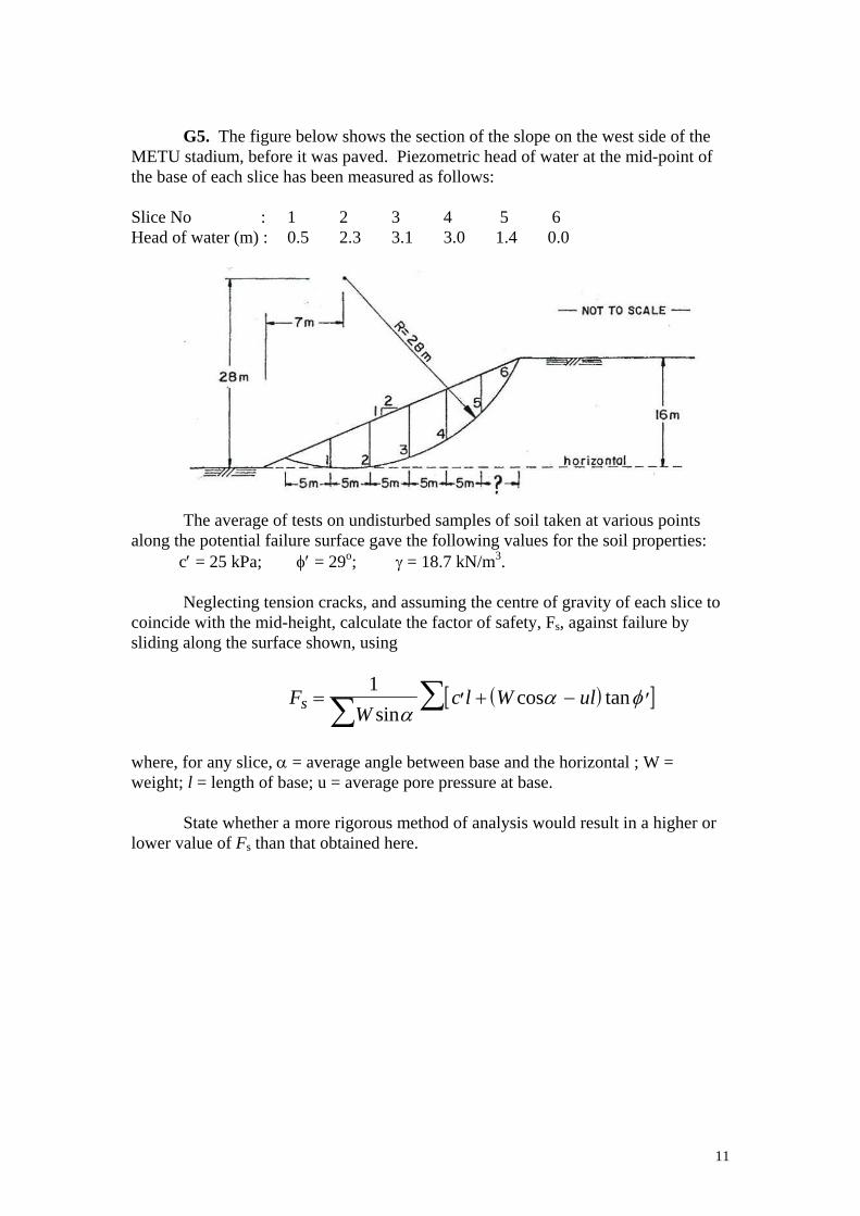
G5. The figure below shows the section of the slope on the west side of the METU stadium, before it was paved. Piezometric head of water at the mid-point of the base of each slice has been measured as follows: Slice No : 1 2 3 4 5 6 Head of water (m) : 0.5 2.3 3.1 3.0 1.4 0.0 The average of tests on undisturbed samples of soil taken at various points along the potential failure surface gave the following values for the soil properties: c′ = 25 kPa; φ′ = 29o; γ = 18.7 kN/m3. Neglecting tension cracks, and assuming the centre of gravity of each slice to coincide with the mid-height, calculate the factor of safety, Fs, against failure by sliding along the surface shown, using
( )[ ]FW
c l W uls = ′ + − ′∑ ∑1sin
cos tanα
α φ
where, for any slice, α = average angle between base and the horizontal ; W = weight; l = length of base; u = average pore pressure at base. State whether a more rigorous method of analysis would result in a higher or lower value of Fs than that obtained here.
12