C:Documents and SettingsBelloniDocumenti MP Filtri Mat.le ...
11
90 LMD 951
Transcript of C:Documents and SettingsBelloniDocumenti MP Filtri Mat.le ...
90
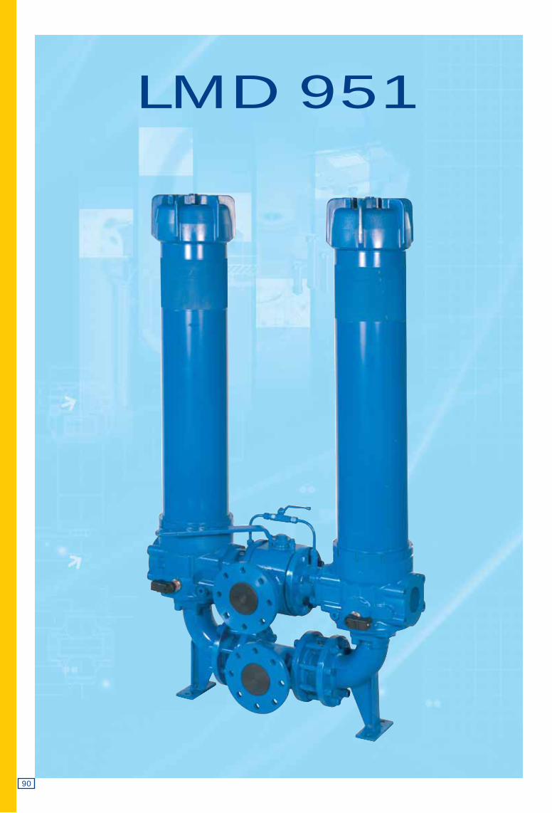
LMD 951
LMD 951
91
D.I. D.I.
D.I. D.I.
D.I. D.I.
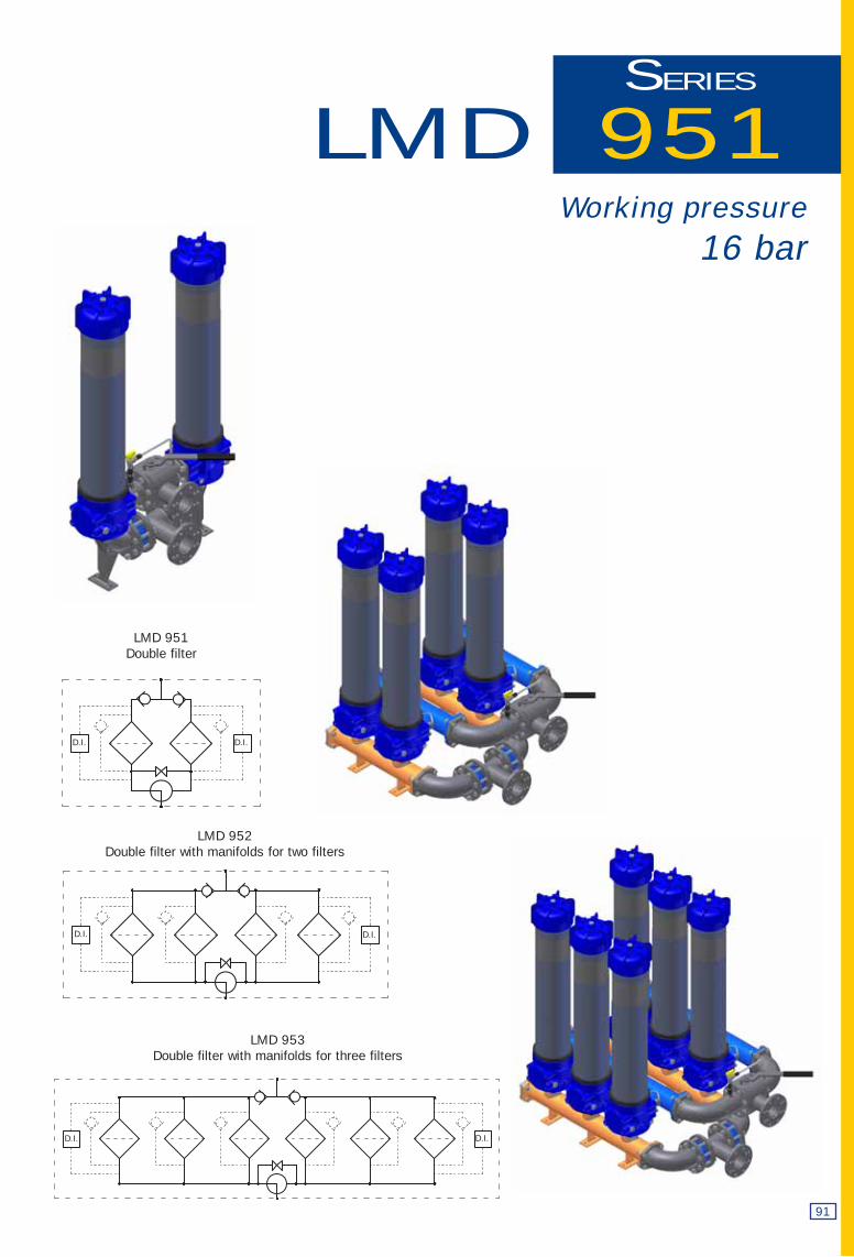
SERIES
LMD 953Double filter with manifolds for three filters
Working pressure16 bar
LMD 951Double filter
LMD 952Double filter with manifolds for two filters
0,9
1,2
0,6
0,3
0,00
0 240 480
800
720 960 1200
DN 80
DN 100
Δp
bar
92
5
6
4
3
2
1
0,00
LMP 951
Δp
bar
0 400 1200 1600 2000
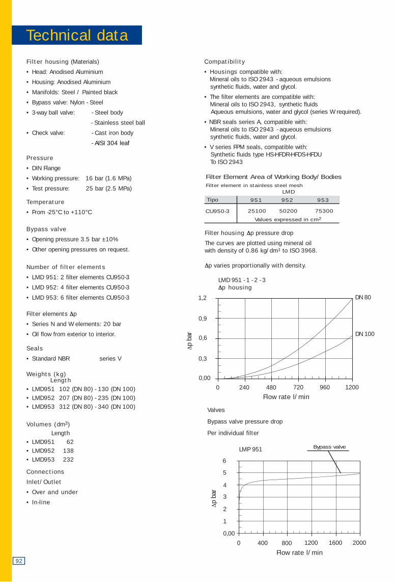
Filter housing (Materials)
• Head: Anodised Aluminium
• Housing: Anodised Aluminium
• Manifolds: Steel / Painted black
• Bypass valve: Nylon - Steel
• 3-way ball valve: - Steel body
- Stainless steel ball
• Check valve: - Cast iron body
- AISI 304 leaf
Pressure
• DIN Flange
• Working pressure: 16 bar (1.6 MPa)
• Test pressure: 25 bar (2.5 MPa)
Temperature
• From -25°C to +110°C
Bypass valve
• Opening pressure 3.5 bar ±10%
• Other opening pressures on request.
Number of filter elements
• LMD 951: 2 filter elements CU950-3
• LMD 952: 4 filter elements CU950-3
• LMD 953: 6 filter elements CU950-3
Filter elements Δp
• Series N and W elements: 20 bar
• Oil flow from exterior to interior.
Seals
• Standard NBR series V
Weights (kg)Length
• LMD951 102 (DN 80) - 130 (DN 100) • LMD952 207 (DN 80) - 235 (DN 100)• LMD953 312 (DN 80) - 340 (DN 100)
Volumes (dm3)Length
• LMD951 62 • LMD952 138 • LMD953 232
Connections
Inlet/Outlet
• Over and under
• In-line
Compatibility
• Housings compatible with:Mineral oils to ISO 2943 - aqueous emulsionssynthetic fluids, water and glycol.
• The filter elements are compatible with: Mineral oils to ISO 2943, synthetic fluidsAqueous emulsions, water and glycol (series W required).
• NBR seals series A, compatible with:Mineral oils to ISO 2943 - aqueous emulsionssynthetic fluids, water and glycol.
• V series FPM seals, compatible with:Synthetic fluids type HS-HFDR-HFDS-HFDUTo ISO 2943
Filter housing Δp pressure drop
The curves are plotted using mineral oil with density of 0.86 kg/dm3 to ISO 3968.
Δp varies proportionally with density.
25100 50200 75300
Filter Element Area of Working Body/BodiesFilter element in stainless steel mesh
951 952 953
CU950-3
Values expressed in cm2
LMD
Tipo
Technical data
LMD 951 - 1 - 2 - 3 Δp housing
Flow rate l/min
Flow rate l/min
Valves
Bypass valve pressure drop
Per individual filter
Bypass valve
3”
2,5 m/sec.
5 m/sec.
750
1500
4”
1200
2400
A
E
F
G
DINPN16
DN100
DINPN16
DN80
99
180
220
18
73
160
200
18
93
D
C
G
B
E
A
F
A
B
C
D
3” SAE
3000 psi/UNC
3” SAE
3000 psi/M
99
106,38
61,93
5/8” UNC
73
106,38
61,93
M16
4” SAE
3000 psi/UNC
4” SAE
3000 psi/M
99
130,18
77,77
5/8” UNC
73
130,18
77,77
M16
Filter Flow rate Filter Flange element l/min Type SAE 3000
type Series N
A03 625
A06 650
A10 700LMD 951 3”
A16 760
A25 780
M25 830
A03 720
A06 750
A10 800LMD 952 3”
A16 800
A25 820
M25 850
A03 780
A06 800
A10 800LMD 953 3”
A16 850
A25 850
M25 880
A03 780
A06 820
A10 900LMD 951 4”
A16 1000
A25 1050
M25 1150
A03 950
A06 980
A10 1050LMD 952 4”
A16 1100
A25 1100
M25 1180
A03 1000
A06 1050
A10 1100LMD 953 4”
A16 1150
A25 1150
M25 1200
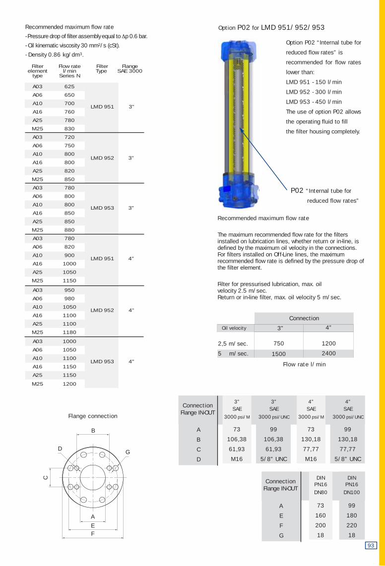
Flange connection
Connection
Oil velocity
Recommended maximum flow rate
The maximum recommended flow rate for the filters installed on lubrication lines, whether return or in-line, isdefined by the maximum oil velocity in the connections.For filters installed on Off-Line lines, the maximum recommended flow rate is defined by the pressure drop ofthe filter element.
Filter for pressurised lubrication, max. oil velocity 2.5 m/sec.Return or in-line filter, max. oil velocity 5 m/sec.
Recommended maximum flow rate
- Pressure drop of filter assembly equal to Δp 0.6 bar.
- Oil kinematic viscosity 30 mm2/s (cSt).
- Density 0.86 kg/dm3.
Option P02 for LMD 951/952/953
Option P02 “Internal tube for
reduced flow rates” is
recommended for flow rates
lower than:
LMD 951 - 150 l/min
LMD 952 - 300 l/min
LMD 953 - 450 l/min
The use of option P02 allows
the operating fluid to fill
the filter housing completely.
P02 “Internal tube for
reduced flow rates”
ConnectionFlange IN-OUT
ConnectionFlange IN-OUT
Flow rate l/min
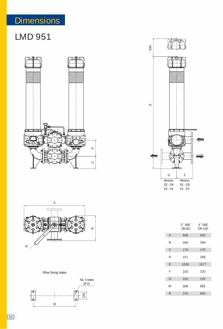
LMD 951
A
B
C
D
E
F
G
M
R
3” SAE 4” SAEDN 80 DN 100
838
346
170
221
1530
220
220
588
370
932
346
170
268
1577
220
220
682
650
94
DC
E93
0
100
M
A
B
R
G
Version:D2 - D4F2 - F4
F
Version:D1 - D3F1 - F3
Dimensions
Filter fixing holes
No. 4 holesØ 15
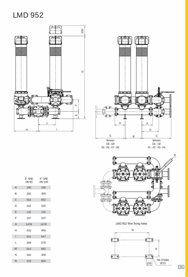
LMD 952
A
B
C
D
E
F
G
H
I
L
M
N
R
3” SAE 4” SAEDN 80 DN 100
190
300
552
332
132
207
1478
432
621
269
614
300
370
190
300
552
332
132
207
1478
456
647
278
662
300
650
95
R
M
100
N
G
FE
H D
B
L
I
930
A A
C
Version:D3 - D4
F5 - F5 - F7 - F8
C
Version:D1 - D2
F1 - F2 - F3 - F4
LMD 952 filter fixing holes
No. 8 holesØ 15
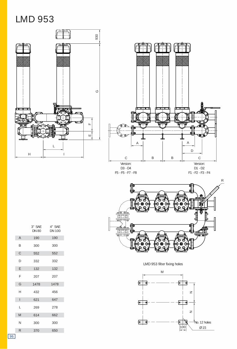
LMD 953
A
B
C
D
E
F
G
H
I
L
M
N
R
3” SAE 4” SAEDN 80 DN 100
190
300
552
332
132
207
1478
432
621
269
614
300
370
190
300
552
332
132
207
1478
456
647
278
662
300
650
96
I
R
H
LA A
D
BB
G
EF
930
M
100
NN
LMD 953 filter fixing holes
No. 12 holes
Ø 15
C
Version:D3 - D4
F5 - F5 - F7 - F8
C
Version:D1 - D2
F1 - F2 - F3 - F4
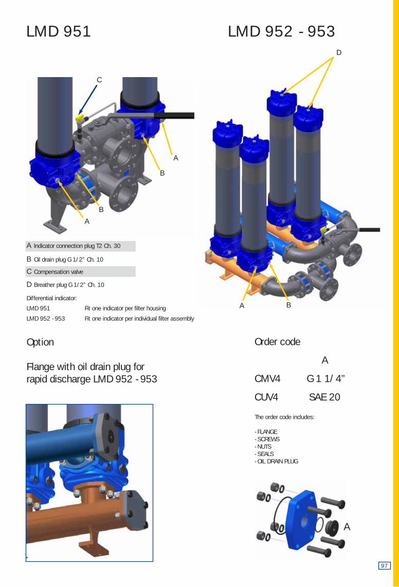
LMD 951 LMD 952 - 953
97
A
C
A
B
A
B
D
BA
Option
Flange with oil drain plug for rapid discharge LMD 952 - 953
The order code includes:
- FLANGE- SCREWS- NUTS- SEALS- OIL DRAIN PLUG
Order code
A
CMV4 G 1 1/4”
CUV4 SAE 20
A Indicator connection plug T2 Ch. 30
B Oil drain plug G 1/2” Ch. 10
C Compensation valve
D Breather plug G 1/2” Ch. 10
Differential indicator:
LMD 951 Fit one indicator per filter housing
LMD 952 - 953 Fit one indicator per individual filter assembly
98
1
1
2
1
6
4
1
16
48
16
16
16
1
2
2
UNI 5931 - M16 x 40 10.9
UNI 1751-B 16
UNI - EN 24032 - M16 10.9
UNI-EN 24014 - M16 x 120 - 10.9 UNI-EN 24014 - M16 x 130 10.9
7
4b
5e 5b 4a
4a
5c5b
3
34a
4b
5a
5b
6
2
1
7
5d
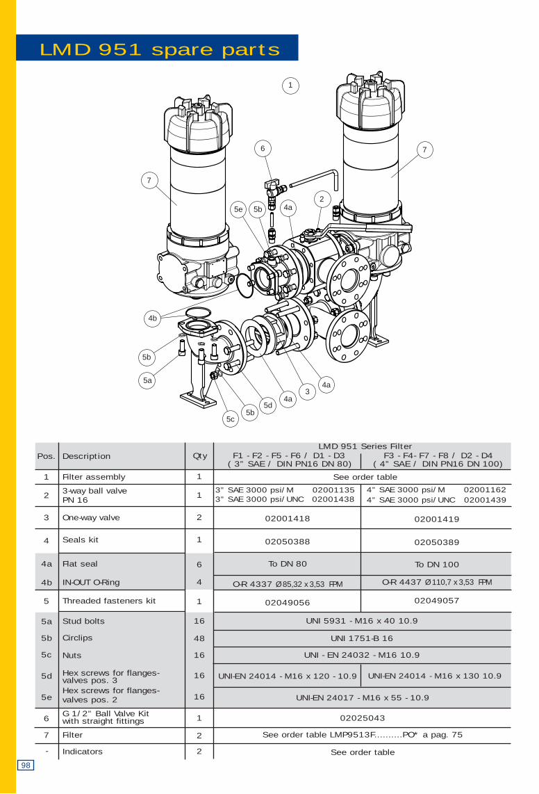
LMD 951 spare parts
Pos.
1
2
3
4
4a
4b
5
5a
5b
5c
5d
5e
6
7
-
QtyDescription
Filter assembly
3-way ball valve PN 16
One-way valve
Seals kit
Flat seal
IN-OUT O-Ring
Threaded fasteners kit
Stud bolts
Circlips
Nuts
Hex screws for flanges-valves pos. 3Hex screws for flanges-valves pos. 2
G 1/2” Ball Valve Kitwith straight fittings
Filter
Indicators
LMD 951 Series Filter F1 - F2 - F5 - F6 / D1 - D3 F3 - F4- F7 - F8 / D2 - D4
( 3” SAE / DIN PN16 DN 80) ( 4” SAE / DIN PN16 DN 100)
See order table
3” SAE 3000 psi/M 020011353” SAE 3000 psi/UNC 02001438
02001418
02050388
To DN 80
O-R 4337 Ø 85,32 x 3,53 FPM
02049056
UNI-EN 24017 - M16 x 55 - 10.9
02025043
See order table LMP9513F..........PO* a pag. 75
See order table
4” SAE 3000 psi/M 020011624” SAE 3000 psi/UNC 02001439
02001419
02050389
To DN 100
O-R 4437 Ø 110,7 x 3,53 FPM
02049057
99
1
1
2
6
1
16
48
32
16
16
1
2
2
UNI-EN 5931 - M16 x 55 10.9
UNI 1751-B 16
UNI-EN 24032 - M16 10.9
UNI-EN 24014 - M16 x 120 10.9UNI-EN 24014 - M16 x 110 10.9
71
4
2
6
7
5a
5b5e
5c5b
5b5c
5d
43
4
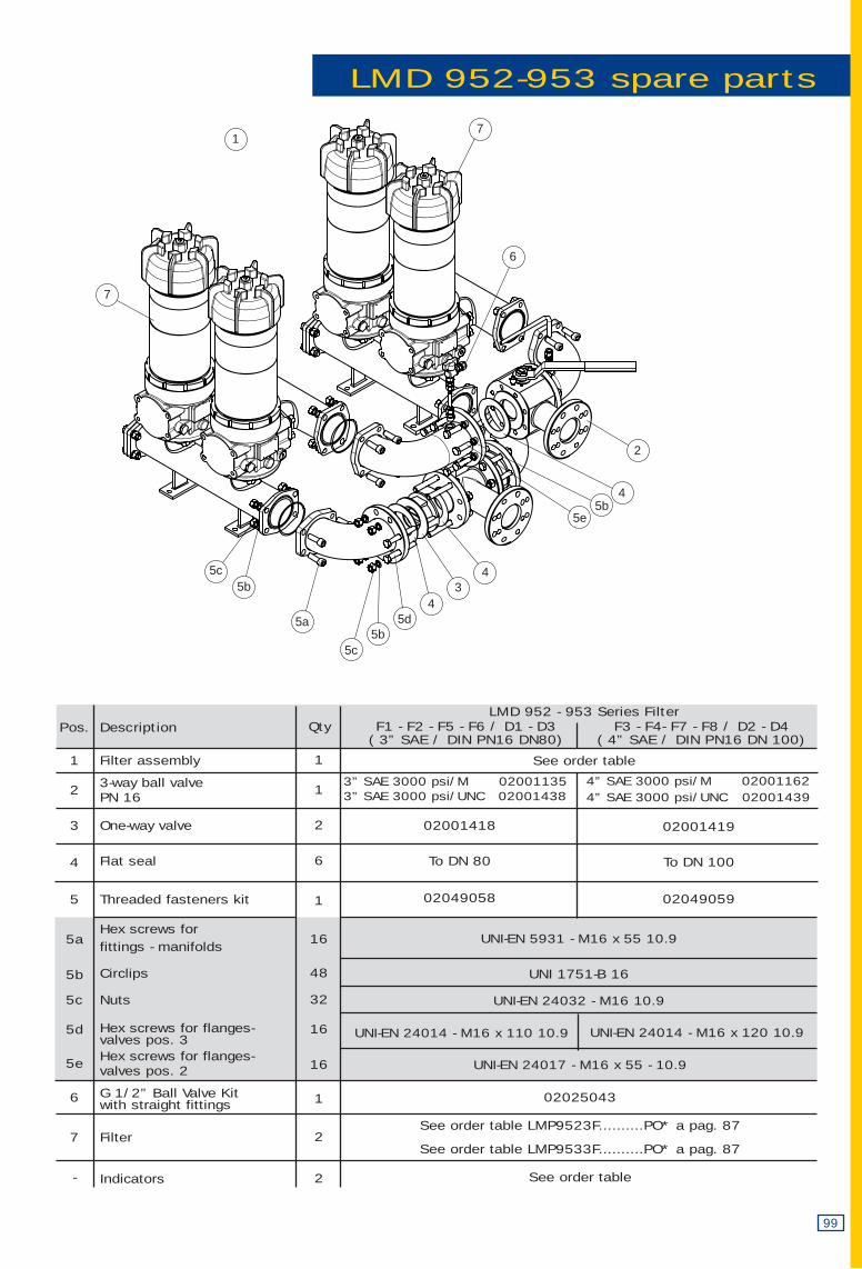
LMD 952-953 spare parts
Pos.
1
2
3
4
5
5a
5b
5c
5d
5e
6
7
-
QtyDescription
Filter assembly
3-way ball valve PN 16
One-way valve
Flat seal
Threaded fasteners kit
Hex screws for fittings - manifolds
Circlips
Nuts
Hex screws for flanges-valves pos. 3Hex screws for flanges-valves pos. 2
G 1/2” Ball Valve Kitwith straight fittings
Filter
Indicators
LMD 952 - 953 Series Filter F1 - F2 - F5 - F6 / D1 - D3 F3 - F4- F7 - F8 / D2 - D4
( 3” SAE / DIN PN16 DN80) ( 4” SAE / DIN PN16 DN 100)
See order table
3” SAE 3000 psi/M 020011353” SAE 3000 psi/UNC 02001438
02001418
To DN 80
02049058
UNI-EN 24017 - M16 x 55 - 10.9
02025043
See order table LMP9523F..........PO* a pag. 87
See order table LMP9533F..........PO* a pag. 87
See order table
4” SAE 3000 psi/M 020011624” SAE 3000 psi/UNC 02001439
02001419
To DN 100
02049059
LMD 1 2 3 4 5 6
2 6 4
7
CU 9507 8b
DIN PN 16 DN 80
DIN PN 16 DN 100
= D1 In-line connections
= D2 In-line connections
D1
D2
D3
D4
3” SAE 3000 psi/M
3” SAE 3000 psi/UNC
4” SAE 3000 psi/M
4” SAE 3000 psi/UNC
= F1 In-line connections
= F2 In-line connections
= F3 In-line connections
= F4 In-line connections
8 a
101
F1
F2
F3
F4
F5
F6
F7
F8
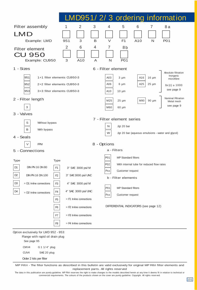
LMD951/2/3 ordering information
8 - Options
a - Filters
P01 MP Standard filters
P02 With internal tube for reduced flow rates
Pxx Customer request
b - Filter elements
P01 MP Standard filters
Pxx Customer request
1 - Sizes
951 1+1 filter elements CU950-3
952 2+2 filter elements CU950-3
953 3+3 filter elements CU950-3
2 - Filter length
3
3 - Valves
S Without by-pass
B With by-pass
4 - Seals
V FPM
5 - Connections
Type Type
Filter assembly
Example: LMD 951 3 B V F1 A10 N P01
Filter element
Example: CU950 3 A10 A N P01
6 - Filter element
A03 3 µm A16 16 µm
A06 6 µm A25 25 µm
A10 10 µm
M25 25 µm M90 90 µm
M60 60 µm
7 - Filter element series
N Δp 20 bar
W Δp 20 bar (aqueous emulsions - water and glycol)
Absolute filtrationInorganicmicrofibre
ßx (c) ≥ 1000
see page 9
Nominal FiltrationMetal mesh
see page 9
Option exclusively for LMD 952 - 953: Flange with rapid oil drain plug
See page 95
CMV4 G 1 1/4” plug
CUV4 SAE 20 plug
Order 2 kits per filter
The data in this publication are purely guideline. MP Filtri reserves the right to make changes to the models described herein at any time it deems fit in relation to technical orcommercial requirements. The colours of the products shown on the cover are purely guideline. Copyright. All rights reserved.
MP Filtri - The filter functions as described in this bulletin are valid exclusively for original MP Filtri filter elements andreplacement parts. All rights reserved
DIFFERENTIAL INDICATORS (see page 12)
![C:Documents and SettingsJohn A. BuckMy ... = (R +jωL)(G+jωC) = [20 +j(6 ×10 8)(0.4 ×10⁻⁶)][80 ×10−3 +j(6 ×10)(40 ×10−12)] = 2.8 +j3.5m−1 = ...](https://static.fdocument.org/doc/165x107/5af606157f8b9a190c8f1f6b/cdocuments-and-settingsjohn-a-buckmy-r-jlgjc-20-j6-10-804.jpg)