Capacitance Meter ( microfarad ) - Gentec - Accueil€¦ · • Battery charger 15VAC ... Fig. 8...
13
Capacitance Meter ( microfarad ) Model NCM-20 INSTRUCTION MANUAL
Transcript of Capacitance Meter ( microfarad ) - Gentec - Accueil€¦ · • Battery charger 15VAC ... Fig. 8...

Capacitance Meter ( microfarad )
Model NCM-20 INSTRUCTION MANUAL
Page 2 of 13
Capacitance Meter NCM-20
USER’S MANUAL
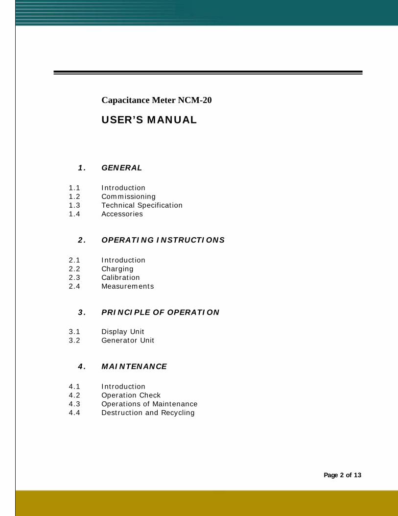
1. GENERAL
1.1 Introduction 1.2 Commissioning 1.3 Technical Specification 1.4 Accessories
2. OPERATING INSTRUCTIONS
2.1 Introduction 2.2 Charging 2.3 Calibration 2.4 Measurements
3. PRINCIPLE OF OPERATION
3.1 Display Unit 3.2 Generator Unit
4. MAINTENANCE
4.1 Introduction 4.2 Operation Check 4.3 Operations of Maintenance 4.4 Destruction and Recycling
Page 3 of 13
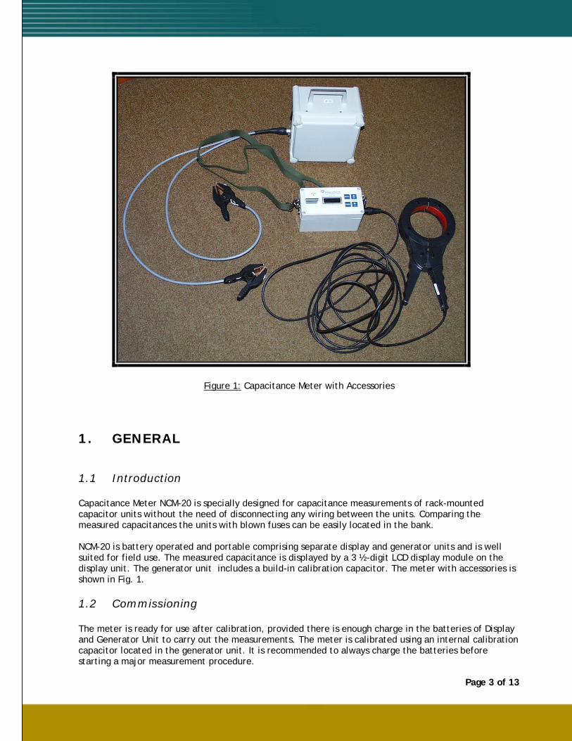
Figure 1: Capacitance Meter with Accessories
1. GENERAL
1.1 Introduction Capacitance Meter NCM-20 is specially designed for capacitance measurements of rack-mounted capacitor units without the need of disconnecting any wiring between the units. Comparing the measured capacitances the units with blown fuses can be easily located in the bank. NCM-20 is battery operated and portable comprising separate display and generator units and is well suited for field use. The measured capacitance is displayed by a 3 ½-digit LCD display module on the display unit. The generator unit includes a build-in calibration capacitor. The meter with accessories is shown in Fig. 1.
1.2 Commissioning
The meter is ready for use after calibration, provided there is enough charge in the batteries of Display and Generator Unit to carry out the measurements. The meter is calibrated using an internal calibration capacitor located in the generator unit. It is recommended to always charge the batteries before starting a major measurement procedure.
Page 4 of 13
1.3 Technical Specification
Connections:
1. Display Unit
• Battery charger 15VAC • Current clamp for measurement of a capacitor unit
2. Generator Unit
• Voltage clips for supplying the measurement voltage 111.86 Hz 1.4 VAC to the bank, 4-wire measurement principle is used
• Battery charger 15VAC • Supply capacity of the Generator Unit is 2000 μF
Measuring ranges:
Range Display 2000 μF 0 … 1999 μF 200 μF 0 … 199.9 μF 20 μF 0 … 19.99 μF
Measurement voltage: 111.86 Hz, 1.4 VAC
± 1% of reading ± 2 digits Operating temperature range: -10°C … +50°C
Maintenance-free sealed lead-acid battery, Generator Unit: 12V 1.2Ah Yuasa NP1.2-12, Display Unit: 6V 1Ah Yuasa NP1-6
appr. 8 h with fully charged batteries depending on bank size
Charging time: 10 … 16 h with discharged batteries
230VAC/15VAC 10.5VA, other primary voltages upon request Dimensions: Display unit: 170 x 80 x 115 mm Generator unit: 190 x 135 x 230 mm Casing: 450 x 350 x 250 mm
Weights: Display unit: 0.95 kg Generator unit: 2.36 kg Casing: 4 kg Current clamp: Chauvin-Arnoux B08-PI: 2 kg
Page 5 of 13
1.4 Accessories
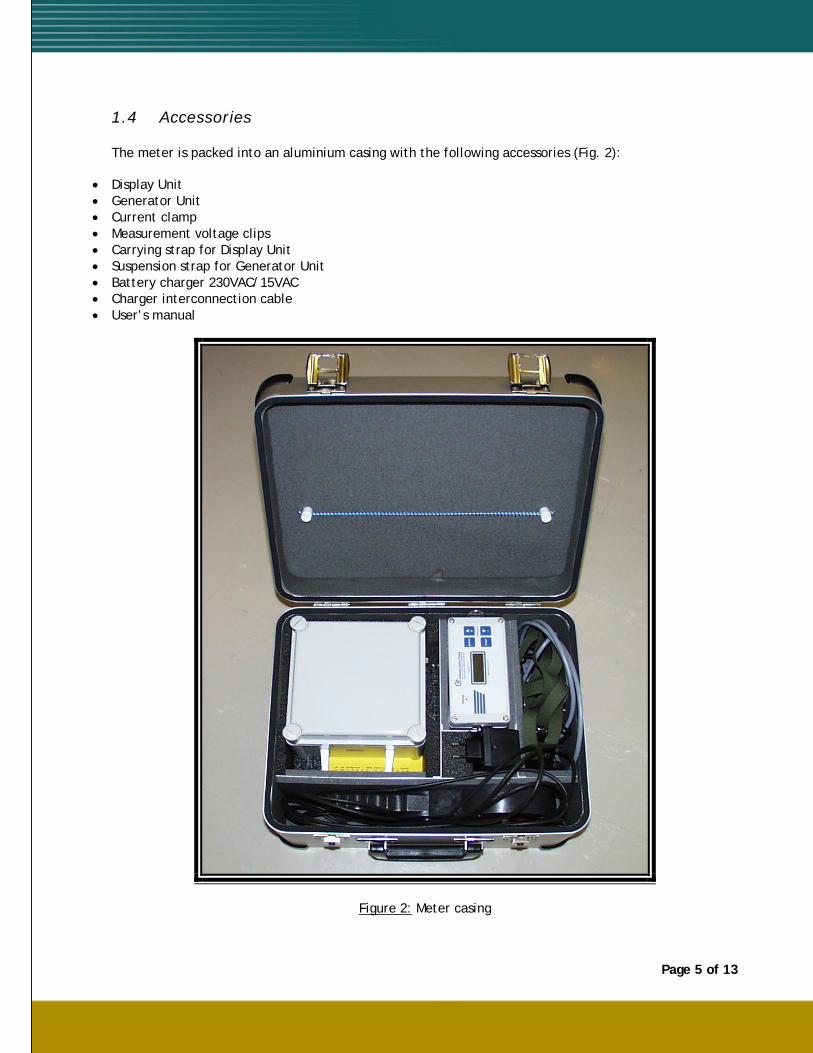
The meter is packed into an aluminium casing with the following accessories (Fig. 2):
• Display Unit • Generator Unit • Current clamp • Measurement voltage clips • Carrying strap for Display Unit • Suspension strap for Generator Unit • Battery charger 230VAC/15VAC • Charger interconnection cable • User’s manual
Figure 2: Meter casing
Page 6 of 13
range
power
charge
calibration
+
-
Capacitance Meter NCM-20
Display Unit
Capacitance [ µF ]
I27.6
1 2 3
7
4
8
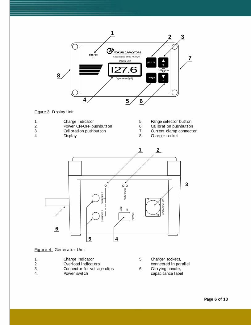
5 6 Figure 3: Display Unit
1. Charge indicator 5. Range selector button 2. Power ON-OFF pushbutton 6. Calibration pushbutton 3. Calibration pushbutton 7. Current clamp connector 4. Display 8. Charger socket
OV
ERLO
AD
VOLT
AG
E C
LIP
S
PO
WER
ON
OFF
CH
ARG
ER 1
CH
AR
GER
215
Vac
1 2
3
45
6
Figure 4: Generator Unit
1. Charge indicator 5. Charger sockets, 2. Overload indicators connected in parallel 3. Connector for voltage clips 6. Carrying handle, 4. Power switch capacitance label
Page 7 of 13
2. OPERATING INSTRUCTIONS
2.1 Introduction
The display and generator of the meter are implemented as separate battery-operated units which facilitates the easy use of the meter. The generator voltage clips are connected to the wiring of the capacitor bank and the generator can be placed to a suitable location using the suspension strap. The display unit can be hanged in the operator’s neck with the carrying strap provided enabling measurement actions at difficult locations, e.g. when using ladders.
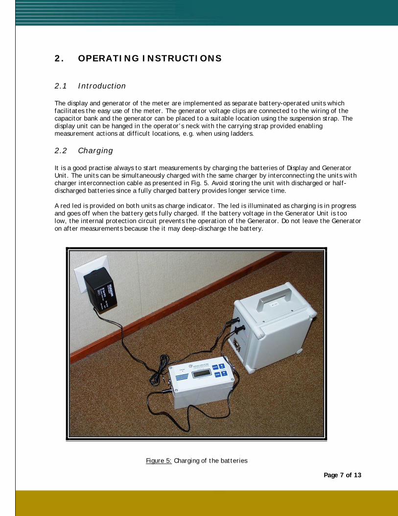
2.2 Charging
It is a good practise always to start measurements by charging the batteries of Display and Generator Unit. The units can be simultaneously charged with the same charger by interconnecting the units with charger interconnection cable as presented in Fig. 5. Avoid storing the unit with discharged or half-discharged batteries since a fully charged battery provides longer service time. A red led is provided on both units as charge indicator. The led is illuminated as charging is in progress and goes off when the battery gets fully charged. If the battery voltage in the Generator Unit is too low, the internal protection circuit prevents the operation of the Generator. Do not leave the Generator on after measurements because the it may deep-discharge the battery.
Figure 5: Charging of the batteries
Page 8 of 13
The charger can be also used separately with either of the units. There are two charger connector sockets on the side of the Generator Unit, one can be used for connection of the mains charger and the other for providing charge to the Display Unit using the interconnection cable provided.
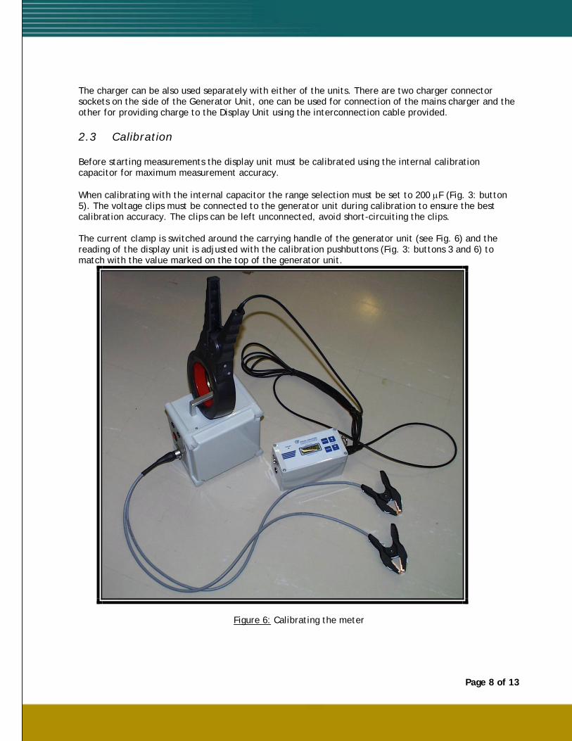
2.3 Calibration
Before starting measurements the display unit must be calibrated using the internal calibration capacitor for maximum measurement accuracy. When calibrating with the internal capacitor the range selection must be set to 200 μF (Fig. 3: button 5). The voltage clips must be connected to the generator unit during calibration to ensure the best calibration accuracy. The clips can be left unconnected, avoid short-circuiting the clips. The current clamp is switched around the carrying handle of the generator unit (see Fig. 6) and the reading of the display unit is adjusted with the calibration pushbuttons (Fig. 3: buttons 3 and 6) to match with the value marked on the top of the generator unit.
Figure 6: Calibrating the meter
Page 9 of 13
2.4 Measurements
The measurement is started by connecting the voltage clips of the generator to the wires connecting capacitor units in parallel.
Make sure that the capacitors to be measured are fully discharged before connecting the voltage clips as discharging the capacitor to the generator output may damage the
generator. Please refer to the Instruction Manual of the capacitor bank
Also avoid short-circuiting the clips as the internal protection fuse may blow. Make sure that both jaws of the clip make a good contact to the wires.
The generator should be connected to the center of the parallel-connected capacitor units so that the current supplied by the generator will be equally divided between all units in the bank to maximize accuracy. Now the generator and display units can be switched on (Fig. 3: button 2 and Fig. 4: switch 4). Check that the both overload leds at the side of the Generator Unit (Fig. 4: 2) are off, otherwise the generator may be overloaded or in short-circuit.
The generator and display units should be kept powered for appr. 15 minutes before starting the actual measurements to let the measurement voltage and display to stabilize. After the warmup the calibration procedure presented in section 2.3 should be carried out. When the meter is calibrated, the actual measurements can take place.
The capacitor unit is measured by selecting a proper measuring range (Fig. 3: 5) and placing the current clamp on the bushing of the capacitor unit and the value can be read out after some seconds as the reading is stabilized. The current clamp should be positioned as far as possible from wires to the lower part of the insulator as the current in wires can weaken the measuring accuracy.
Page 10 of 13
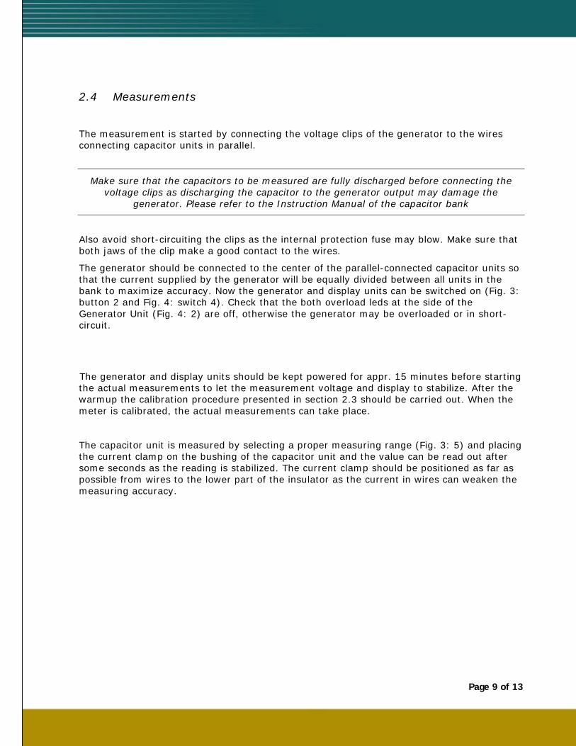
Fig. 7 shows a practical measurement action.
Fig. 7: Practical capacitor measurement
Page 11 of 13
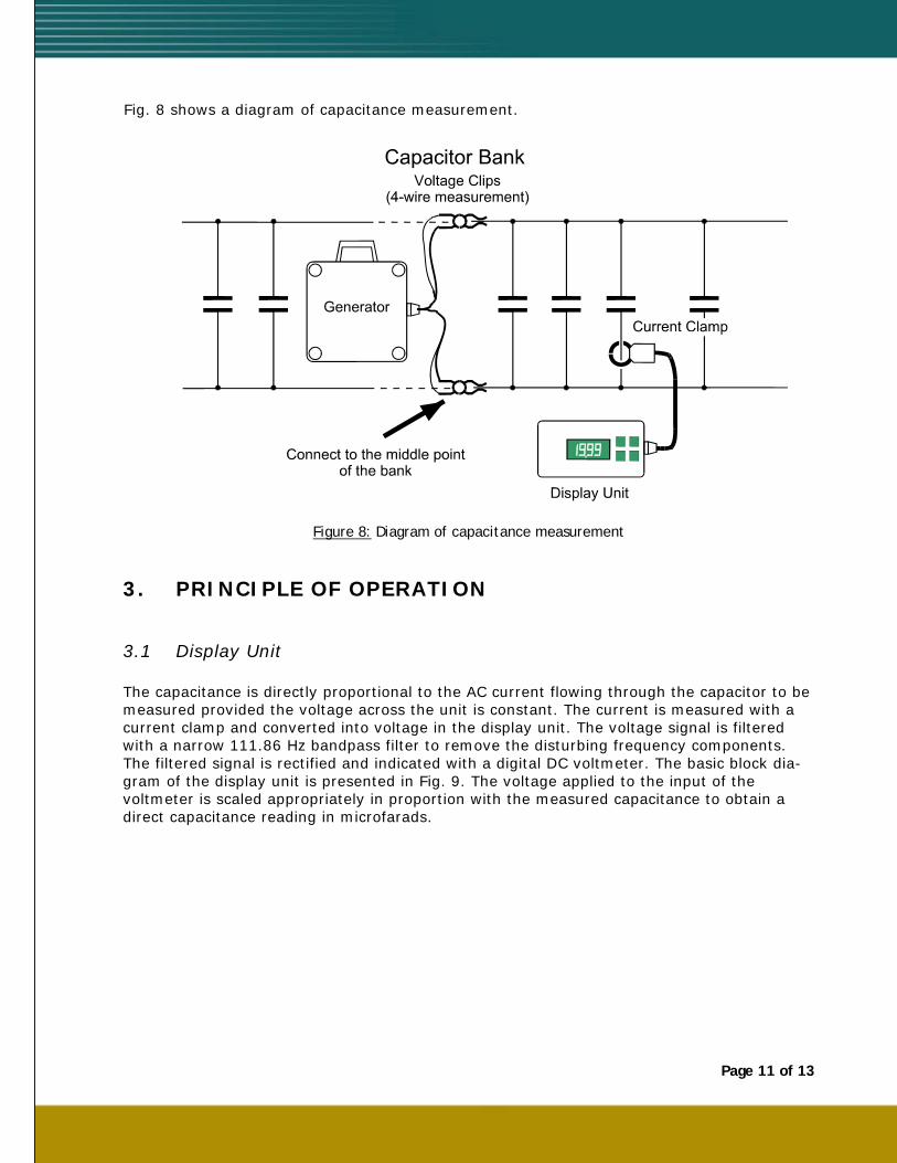
Fig. 8 shows a diagram of capacitance measurement.
Figure 8: Diagram of capacitance measurement
3. PRINCIPLE OF OPERATION
3.1 Display Unit
The capacitance is directly proportional to the AC current flowing through the capacitor to be measured provided the voltage across the unit is constant. The current is measured with a current clamp and converted into voltage in the display unit. The voltage signal is filtered with a narrow 111.86 Hz bandpass filter to remove the disturbing frequency components. The filtered signal is rectified and indicated with a digital DC voltmeter. The basic block dia-gram of the display unit is presented in Fig. 9. The voltage applied to the input of the voltmeter is scaled appropriately in proportion with the measured capacitance to obtain a direct capacitance reading in microfarads.
Page 12 of 13
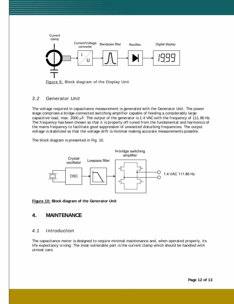
Figure 9: Block diagram of the Display Unit
3.2 Generator Unit
The voltage required in capacitance measurement is generated with the Generator Unit. The power stage comprises a bridge-connected switching amplifier capable of feeding a considerably large capacitive load, max. 2000 μF. The output of the generator is 1.4 VAC with the frequency of 111.86 Hz. The frequency has been chosen so that it is properly off-tuned from the fundamental and harmonics of the mains frequency to facilitate good suppression of unwanted disturbing frequencies. The output voltage is stabilized so that the voltage drift is minimal making accurate measurements possible. The block diagram is presented in Fig. 10.
Figure 10: Block diagram of the Generator Unit 4. MAINTENANCE
4.1 Introduction
The capacitance meter is designed to require minimal maintenance and, when operated properly, its life expectancy is long. The most vulnerable part is the current clamp which should be handled with utmost care.
4.2 Operation check
The operation of the meter can be checked with the following simple procedure:
1. Switch on the generator. Observe the two red indicator lights on the side panel (Fig. 4: 2). The other should light when switching the unit on and go out after a few seconds. If this happens, the generator is probably operational. Another method to check the operation of the generator is to measure the output voltage which should be around 1.4 … 1.5 VAC with the frequency of 111.86 Hz. The indicator lights can be on if the load is too high or in short-circuit. If the battery is discharged, the generator will not start, in this case charge the battery.
2. Switch on the display unit and clip the current clamp around the carrying handle of the generator as presented in section 2.3. The display should indicate a reading close to the capacitance of the calibration capacitor adjustable to the correct value with the calibration pushbuttons.
3. Switch off the generator. The display should decrease to zero. 4. If the display unit operates as described in 2. and 3., it is in working condition.
4.3 Operations of maintenance Generator Unit: If the output voltage of the unit is measured to be zero, the internal protection fuse is probably blown. Open the cover and check the fuse on the circuit board. Replace with a new one when required. The fuse rating is 6.3 x 32 mm 7 A, fast acting. Display Unit:
There are no user-maintainable parts in the unit. Current clamp (concerns model Midori CT-65): The air gaps of the current clamp must be held clean. Dust and foreign particles can cause erraneous readings. The gaps can be cleaned e.g. by drawing a piece of paper through the gaps. No abrasive material, e.g. sandpaper must not be used. The thin plates can bend easily and the clamp will not close properly. In this case the plates must be carefully realigned in order to close without using excessive force. Opening and closing can be facilitated by a squeeze of lubricating oil (CRC-56 or equivalent) between the plates. Check regularly the condition of all the cables of the meter. If the meter has got wet e.g. in field use, do not store it tightly closed but first let the moisture to evaporate. If the meter is to be stored for a long period of time, the batteries must be fully charged prior to storing.
4.4 Destruction and recycling
The cases of the Display and Generator units are made of ABS plastic and can be recycled or destructed in accordance with the local regulations.
The carrying case is made mostly of aluminium and can be recycled. The printed circuit boards contain no recyclable parts and must be disposed as electronics waste.
The batteries are to be treated as hazardous waste and must be disposed accordingly.