Bulk solid stability on inclined belt conveyorst.tribologia.org/plik/spm/spmom-11v46n4_071.pdf ·...
20
Bulk solid stability on inclined belt conveyors 71 SCIENTIFIC PROBLEMS OF MACHINES OPERATION AND MAINTENANCE 4 (168) 2011 STANISLAW F. ŚCIESZKA * , DANIEL ADAMECKI * Bulk solid stability on inclined belt conveyors Key words Belt conveyor, inclination angle, coefficient of wall friction, external friction. Slowa k luczowe Przenośnik taśmowy, kąt nachylenia, wspólczynnik tarcia zewnętrznego, tarcie powierzchniowe. Summary A new experimental methodology is described for combined measurements of both the static and kinetic friction between bulk solid and the conveyor belt. This area of investigation has been all too often neglected. The method of testing is based on the very well know principle of operation of the inclined plane. The tester was designed having in mind that tribological phenomena are influenced by various factors; therefore, these factors should be varied widely and independently, and they should be measured easily. In this, preliminary testing using two coals, two rubber belts and several different operational conditions were used, such as loads and moisture content. The experimental results confirm that both static and kinetic angles of friction between the belts surfaces and the coals tested are considerable higher than the presently recommended maximum inclination angle for belt conveyors. Bulk materials are not the same, and this is the reason why physical testing of a bulk solid is so important to proper design of conveying systems. * Silesian University of Technology, Faculty of Mining and Geology, Institute of Mining Mechanisation, Akademicka 2A Street, 44-100 Gliwice, Poland; [email protected].
Transcript of Bulk solid stability on inclined belt conveyorst.tribologia.org/plik/spm/spmom-11v46n4_071.pdf ·...
Bulk solid stability on inclined belt conveyors 71
SCIENTIFIC PROBLEMS OF MACHINES OPERATION AND MAINTENANCE
4 (168) 2011
STANISŁAW F. ŚCIESZKA*, DANIEL ADAMECKI *
Bulk solid stability on inclined belt conveyors
K e y w o r d s
Belt conveyor, inclination angle, coefficient of wall friction, external friction.
S ł o w a k l u c z o w e
Przenośnik taśmowy, kąt nachylenia, współczynnik tarcia zewnętrznego, tarcie powierzchniowe.
S u m m a r y
A new experimental methodology is described for combined measurements of both the static and kinetic friction between bulk solid and the conveyor belt. This area of investigation has been all too often neglected. The method of testing is based on the very well know principle of operation of the inclined plane. The tester was designed having in mind that tribological phenomena are influenced by various factors; therefore, these factors should be varied widely and independently, and they should be measured easily. In this, preliminary testing using two coals, two rubber belts and several different operational conditions were used, such as loads and moisture content. The experimental results confirm that both static and kinetic angles of friction between the belts surfaces and the coals tested are considerable higher than the presently recommended maximum inclination angle for belt conveyors. Bulk materials are not the same, and this is the reason why physical testing of a bulk solid is so important to proper design of conveying systems.
* Silesian University of Technology, Faculty of Mining and Geology, Institute of Mining
Mechanisation, Akademicka 2A Street, 44-100 Gliwice, Poland; [email protected].
S.F. Ścieszka, D. Adamecki 72
Introduction
The modern and future trend in surface and underground mining is to eliminate or combine functions and to increase continuity. In coal or soft ores continuous miners or longwall shearers break and excavate mechanically and thus eliminate drilling and blasting. The continuity in transportation is also advantageous [1]. As a consequence, the cyclic haulage and hoisting methods and equipment, such as truck (trailer), rail (train), and skip (cage) will receive increasing competition in the future from the belt conveyor. Conventional troughed belt conveyors, thanks to such advantages as low operating cost, good gradeability, high output and proven reliability are already the most widely used continuous haulage machines [1, 2, 3]. Their usage in in-plant movement of materials, long distance overland, and underground transportation is now widely established. Economic evaluations highlight the advantages of employing a speed greater than 6 m/s [2, 4]. The trend towards higher operating speed on inclined belt conveyors emphasises the importance of the interaction between the bulk solid and the belt during conveying, feeding, and discharge [4, 5]. The frictional interaction between the bulk solid and the belt is critical for the stability of the bulk solid on the conveyor belt during motion under various loading conditions and along a combination of horizontal and vertical curves, particularly, during starting and stopping of the conveyor [4, 5]. The bulk solid is subjected to horizontal acceleration as the result of the belt movement between the idlers (providing that the belt sag, ymax > 0) [5], which induces the reduction of both the normal interaction and surface friction between the bulk solid and the belt leading to slip during inclined conveying. If the belt speed is fast enough, then lift-off and fall-back may occur. Both slip and lift-off can increase spillage.
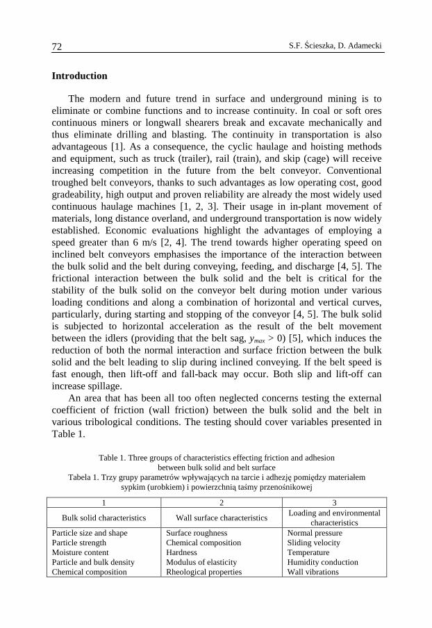
An area that has been all too often neglected concerns testing the external coefficient of friction (wall friction) between the bulk solid and the belt in various tribological conditions. The testing should cover variables presented in Table 1.
Table 1. Three groups of characteristics effecting friction and adhesion
between bulk solid and belt surface Tabela 1. Trzy grupy parametrów wpływających na tarcie i adhezję pomiędzy materiałem
sypkim (urobkiem) i powierzchnią taśmy przenośnikowej
1 2 3
Bulk solid characteristics Wall surface characteristics Loading and environmental
characteristics Particle size and shape Particle strength Moisture content Particle and bulk density Chemical composition
Surface roughness Chemical composition Hardness Modulus of elasticity Rheological properties
Normal pressure Sliding velocity Temperature Humidity conduction Wall vibrations
Bulk solid stability on inclined belt conveyors 73
Belt conveyors are frequently operated on an upward and downward incline. The angles of maximum inclination are recommended on the basis of wide previous experiences and vary for coal from 15° to 20° [6, 7, 8]. The recommended angles are far below the actual values of the angles of friction between belt surface and the conveyed bulk solid. The angles recommendation is rather conservative, and its procedure is lacking in well documented experimental results from a tribological investigations on the coefficient of static and kinetic friction between the specific bulk solid (e.g. coal with described essential characteristic – one coal is not all coal) and the carrying surface (e.g. rubber belt with essential material and surface characteristics). There were two objectives of this work: firstly, to develop a method of testing based on the very well-known principle of operation of the inclined plane, and, secondly, to supplement results published so far [7–10] using the method and apparatus.
Bulk solid and conveyor belt interaction
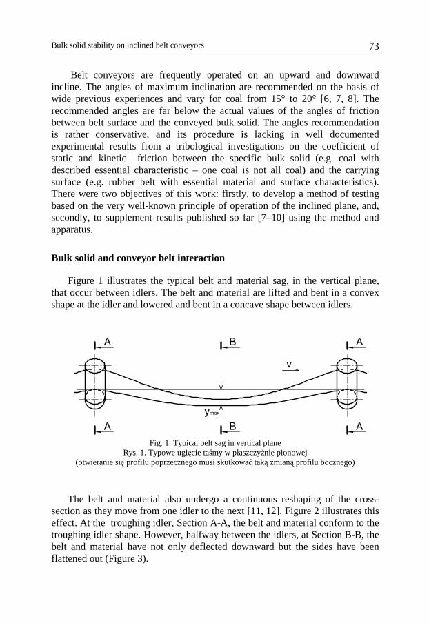
Figure 1 illustrates the typical belt and material sag, in the vertical plane, that occur between idlers. The belt and material are lifted and bent in a convex shape at the idler and lowered and bent in a concave shape between idlers.
Fig. 1. Typical belt sag in vertical plane
Rys. 1. Typowe ugięcie taśmy w płaszczyźnie pionowej (otwieranie się profilu poprzecznego musi skutkować taką zmianą profilu bocznego)
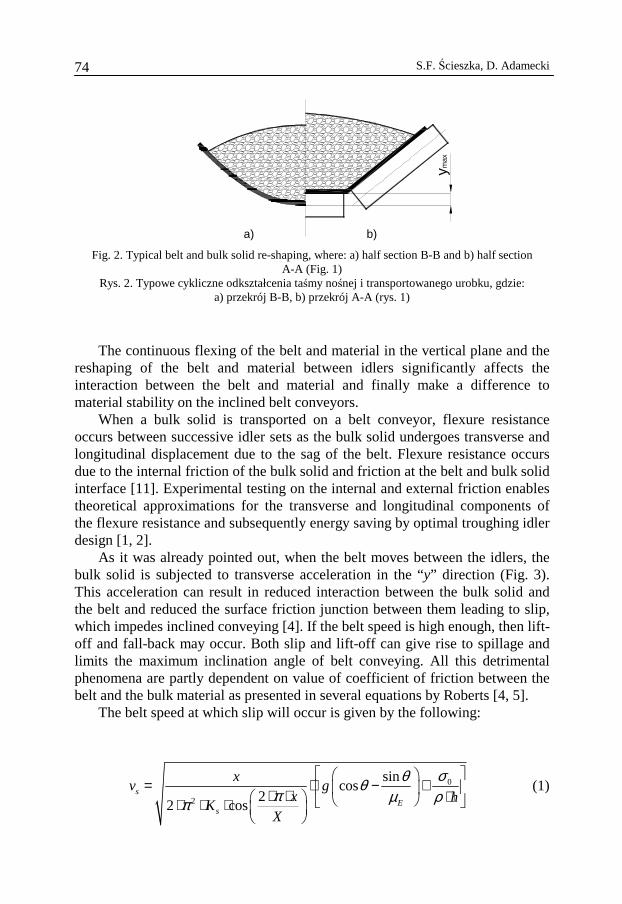
The belt and material also undergo a continuous reshaping of the cross-section as they move from one idler to the next [11, 12]. Figure 2 illustrates this effect. At the troughing idler, Section A-A, the belt and material conform to the troughing idler shape. However, halfway between the idlers, at Section B-B, the belt and material have not only deflected downward but the sides have been flattened out (Figure 3).
S.F. Ścieszka, D. Adamecki 74
ymax
a) b)
Fig. 2. Typical belt and bulk solid re-shaping, where: a) half section B-B and b) half section A-A (Fig. 1)
Rys. 2. Typowe cykliczne odkształcenia taśmy nośnej i transportowanego urobku, gdzie: a) przekrój B-B, b) przekrój A-A (rys. 1)
The continuous flexing of the belt and material in the vertical plane and the reshaping of the belt and material between idlers significantly affects the interaction between the belt and material and finally make a difference to material stability on the inclined belt conveyors.
When a bulk solid is transported on a belt conveyor, flexure resistance occurs between successive idler sets as the bulk solid undergoes transverse and longitudinal displacement due to the sag of the belt. Flexure resistance occurs due to the internal friction of the bulk solid and friction at the belt and bulk solid interface [11]. Experimental testing on the internal and external friction enables theoretical approximations for the transverse and longitudinal components of the flexure resistance and subsequently energy saving by optimal troughing idler design [1, 2].
As it was already pointed out, when the belt moves between the idlers, the bulk solid is subjected to transverse acceleration in the “y” direction (Fig. 3). This acceleration can result in reduced interaction between the bulk solid and the belt and reduced the surface friction junction between them leading to slip, which impedes inclined conveying [4]. If the belt speed is high enough, then lift-off and fall-back may occur. Both slip and lift-off can give rise to spillage and limits the maximum inclination angle of belt conveying. All this detrimental phenomena are partly dependent on value of coefficient of friction between the belt and the bulk material as presented in several equations by Roberts [4, 5].
The belt speed at which slip will occur is given by the following:
0
2
sincos
22 cos
sE
s
xv g
x hK
X
σθθπ µ ρπ
= ⋅ − + ⋅ ⋅ ⋅ ⋅ ⋅ ⋅
(1)
Bulk solid stability on inclined belt conveyors 75
y
x
C
BC
λ
β
z
a
c
b v
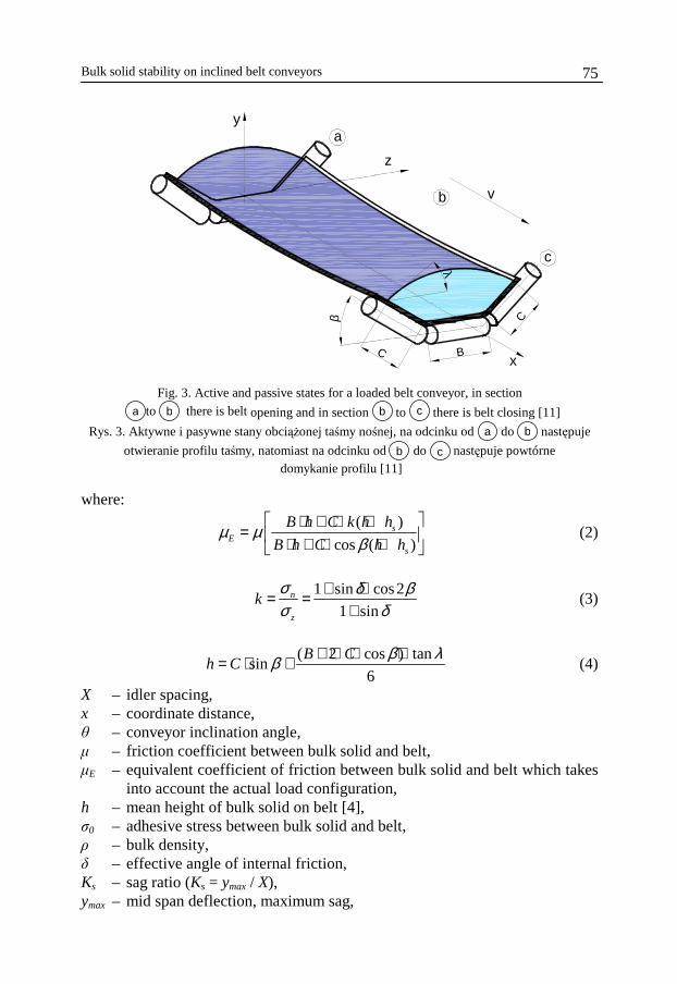
Fig. 3. Active and passive states for a loaded belt conveyor, in section
to there is belt opening and in section to there is belt closing [11]
Rys. 3. Aktywne i pasywne stany obciążonej taśmy nośnej, na odcinku od do następuje
otwieranie profilu taśmy, natomiast na odcinku od do następuje powtórne domykanie profilu [11]
where:
( )
cos ( )s
Es
B h C k h h
B h C h hµ µ
β ⋅ + ⋅ +
= ⋅ + ⋅ + (2)
1 sin cos2
1 sinn
z
kσ δ βσ δ
+ ⋅= =+
(3)
( 2 cos ) tan
sin6
B Ch C
β λβ + ⋅ ⋅ ⋅= ⋅ + (4)
X – idler spacing, x – coordinate distance, θ – conveyor inclination angle, µ – friction coefficient between bulk solid and belt, µE – equivalent coefficient of friction between bulk solid and belt which takes
into account the actual load configuration, h – mean height of bulk solid on belt [4], σ0 – adhesive stress between bulk solid and belt, ρ – bulk density, δ – effective angle of internal friction, Ks – sag ratio (Ks = ymax / X), ymax – mid span deflection, maximum sag,
b a
c b
b a
c b
S.F. Ścieszka, D. Adamecki 76
β – troughing angle (Figure 3), λ – surcharge angle (Figure 3), k – pressure ratio [4], g – acceleration of gravity, σn – normal stress to the surface, σz – stress on the vertical.
Slip commences when x = X/4 or x = 3X/4. Lift-off occurs when the normal pressure between the bulk solid and belt surface becomes zero. It as shown by Roberts [4, 5] that the belt velocity for lift-off to occur is given by the following:
0
2
cos2
2 cosL
s
xv g
x hK
X
σθπ ρπ
= ⋅ ⋅ + ⋅ ⋅ ⋅ ⋅ ⋅ ⋅
(5)
The minimum belt velocity for lift-off to take place corresponds to x = 0 or x = X. The adhesive stress between the bulk solid and the belt surface can be assume to be zero, so the equation can be simplified to the following form:
2max
cos cos
2 2Ls
x g x gv
K y
θ θπ π
⋅ ⋅ ⋅= = ⋅⋅ ⋅ ⋅
(6)
Equation (6) proves that the reduction of sag ratio increases the belt speed for slip and lift-off to occur. Equation (1) confirms that an increase of the equivalent coefficient of friction will increase the belt speed at which slip starts to occur.
Friction tests and testing techniques
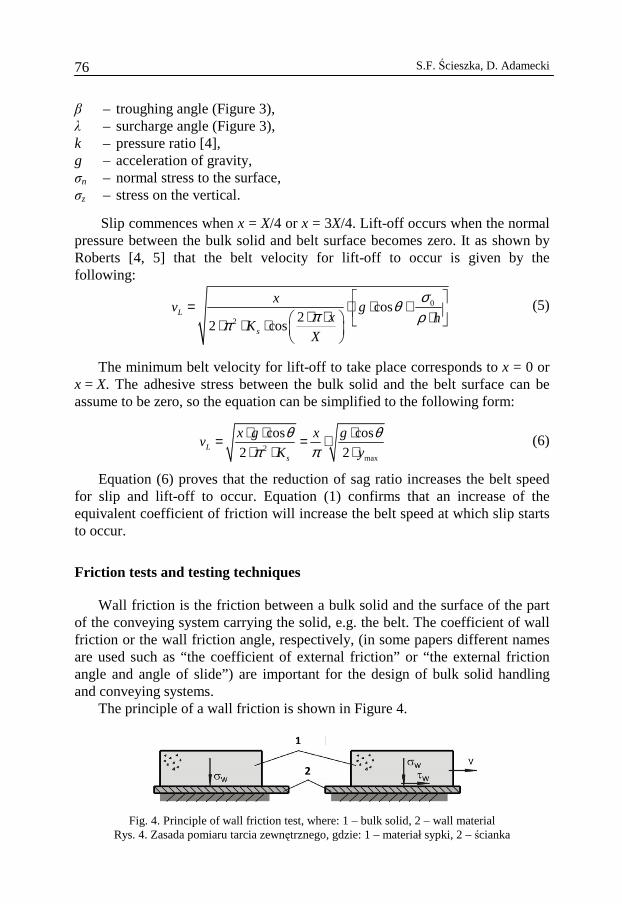
Wall friction is the friction between a bulk solid and the surface of the part of the conveying system carrying the solid, e.g. the belt. The coefficient of wall friction or the wall friction angle, respectively, (in some papers different names are used such as “the coefficient of external friction” or “the external friction angle and angle of slide”) are important for the design of bulk solid handling and conveying systems.
The principle of a wall friction is shown in Figure 4.
1
2
Fig. 4. Principle of wall friction test, where: 1 – bulk solid, 2 – wall material Rys. 4. Zasada pomiaru tarcia zewnętrznego, gdzie: 1 – materiał sypki, 2 – ścianka
Bulk solid stability on inclined belt conveyors 77
The coefficient of wall friction, µ, is the ratio of wall shear, τw, to wall normal stress, σw:
tanw
w
τµ ϕσ
= = (7)
The wall friction angle, ϕ, is the slope of a line running through the origin of the σw, τw, diagram and a point of the wall yield locus.
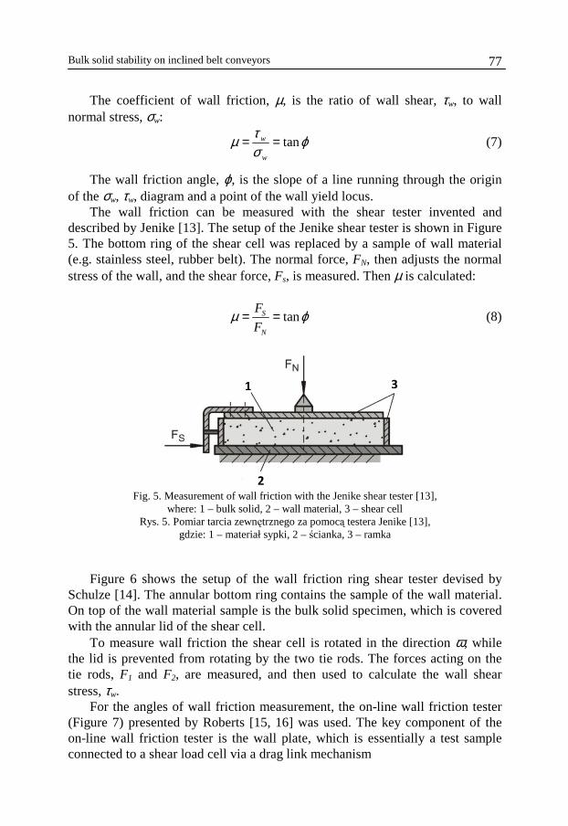
The wall friction can be measured with the shear tester invented and described by Jenike [13]. The setup of the Jenike shear tester is shown in Figure 5. The bottom ring of the shear cell was replaced by a sample of wall material (e.g. stainless steel, rubber belt). The normal force, FN, then adjusts the normal stress of the wall, and the shear force, Fs, is measured. Then µ is calculated:
tanS
N
F
Fµ ϕ= = (8)
1 3
2 Fig. 5. Measurement of wall friction with the Jenike shear tester [13],
where: 1 – bulk solid, 2 – wall material, 3 – shear cell Rys. 5. Pomiar tarcia zewnętrznego za pomocą testera Jenike [13],
gdzie: 1 – materiał sypki, 2 – ścianka, 3 – ramka
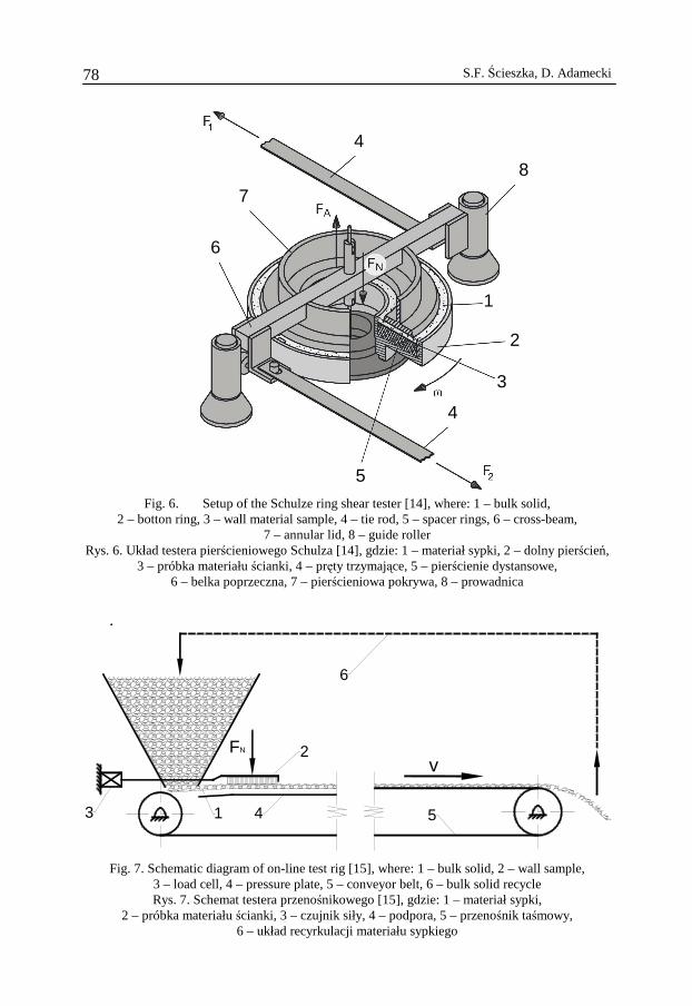
Figure 6 shows the setup of the wall friction ring shear tester devised by
Schulze [14]. The annular bottom ring contains the sample of the wall material. On top of the wall material sample is the bulk solid specimen, which is covered with the annular lid of the shear cell.
To measure wall friction the shear cell is rotated in the direction ω, while the lid is prevented from rotating by the two tie rods. The forces acting on the tie rods, F1 and F2, are measured, and then used to calculate the wall shear stress, τw.
For the angles of wall friction measurement, the on-line wall friction tester (Figure 7) presented by Roberts [15, 16] was used. The key component of the on-line wall friction tester is the wall plate, which is essentially a test sample connected to a shear load cell via a drag link mechanism
S.F. Ścieszka, D. Adamecki 78
1
2
3
4
5
6
7
4
8
Fig. 6. Setup of the Schulze ring shear tester [14], where: 1 – bulk solid,
2 – botton ring, 3 – wall material sample, 4 – tie rod, 5 – spacer rings, 6 – cross-beam, 7 – annular lid, 8 – guide roller
Rys. 6. Układ testera pierścieniowego Schulza [14], gdzie: 1 – materiał sypki, 2 – dolny pierścień, 3 – próbka materiału ścianki, 4 – pręty trzymające, 5 – pierścienie dystansowe,
6 – belka poprzeczna, 7 – pierścieniowa pokrywa, 8 – prowadnica
.
FN
v
6
4 53
2
1
Fig. 7. Schematic diagram of on-line test rig [15], where: 1 – bulk solid, 2 – wall sample, 3 – load cell, 4 – pressure plate, 5 – conveyor belt, 6 – bulk solid recycle Rys. 7. Schemat testera przenośnikowego [15], gdzie: 1 – materiał sypki,
2 – próbka materiału ścianki, 3 – czujnik siły, 4 – podpora, 5 – przenośnik taśmowy, 6 – układ recyrkulacji materiału sypkiego
Bulk solid stability on inclined belt conveyors 79
A test bulk solid of controlled depth is passed underneath the wall sample, and the friction force acting between the wall plate and bulk solid is sensed by the load cell. To adjust the normal stress normal load, FN, was applied to the top surface of the wall test sample. Several problems have been encountered with the on-line tester [15], such as low reliability, high cost of operation, bulk materials degradation, and dust generation. Tribological phenomena, i.e. the static and kinetic friction between bulk solid and belt are influenced by various factors. Therefore, in friction tests in the laboratory, these factors should be varied widely and independently, and they should be easy to measure. None of the above presented testers satisfied the requirements e.g., changing the bulk solid sample is very inconvenient in the on-line tested, and, in the Jenike tester, there is a very limited range of variation in sliding speeds. Therefore a new test-rig was designed and built.
Experimental details
Experimental apparatus and procedures
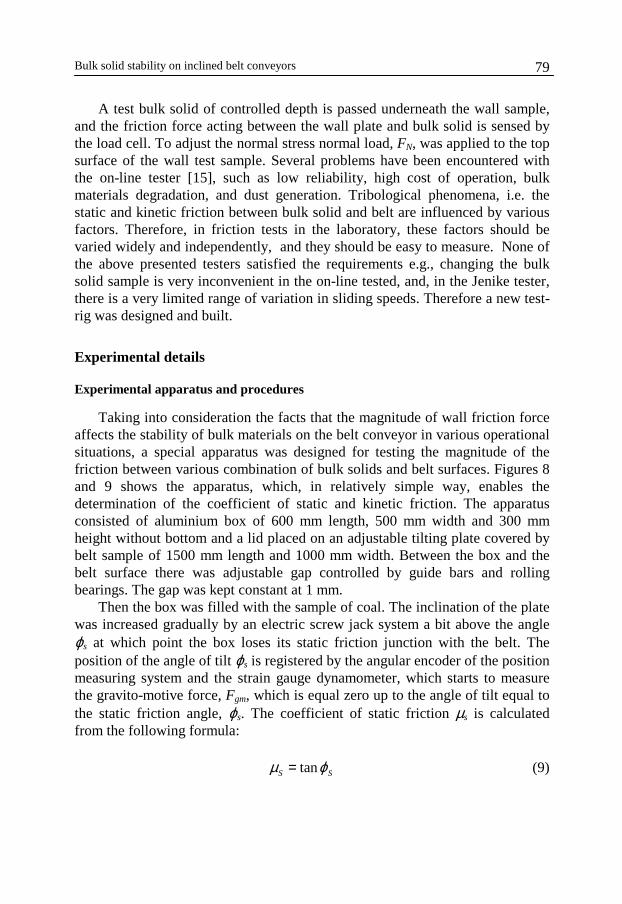
Taking into consideration the facts that the magnitude of wall friction force affects the stability of bulk materials on the belt conveyor in various operational situations, a special apparatus was designed for testing the magnitude of the friction between various combination of bulk solids and belt surfaces. Figures 8 and 9 shows the apparatus, which, in relatively simple way, enables the determination of the coefficient of static and kinetic friction. The apparatus consisted of aluminium box of 600 mm length, 500 mm width and 300 mm height without bottom and a lid placed on an adjustable tilting plate covered by belt sample of 1500 mm length and 1000 mm width. Between the box and the belt surface there was adjustable gap controlled by guide bars and rolling bearings. The gap was kept constant at 1 mm.
Then the box was filled with the sample of coal. The inclination of the plate was increased gradually by an electric screw jack system a bit above the angle ϕs at which point the box loses its static friction junction with the belt. The position of the angle of tilt ϕs is registered by the angular encoder of the position measuring system and the strain gauge dynamometer, which starts to measure the gravito-motive force, Fgm, which is equal zero up to the angle of tilt equal to the static friction angle, ϕs. The coefficient of static friction µs is calculated from the following formula:
tanS Sµ ϕ= (9)
S.F. Ścieszka, D. Adamecki 80
Stop
10
39
68 51
2
4
7
Fig. 8. Schematic diagram of the incline plane test rig, where: 1 – box (shear cell),
2 – adjustable tilting plate (inclined plane), 3 – conveyor belt (wall sample), 4 – electric screw jack system, 5 – dynamometer, 6 – encoder reading head, 7 – encoder magnetic rule,
8 – guide bars, 9 – angular encoder, 10 – controller. Rys. 8. Schemat stanowiska badawczego – równia pochyła, gdzie: 1 – ramka z materiałem sypkim,
2 – regulowana równia pochyła, 3 – wycinek taśmy przenośnikowej, 4 – podnośnik śrubowy, 5 – dynamometr, 6 – głowica odczytowa sensora położenia liniowego, 7 – taśma magnetyczna
sensora, 8 – sztywne prowadzenie ramki, 9 – inkrementalny sensor położenia kątowego, 10 – sterownik
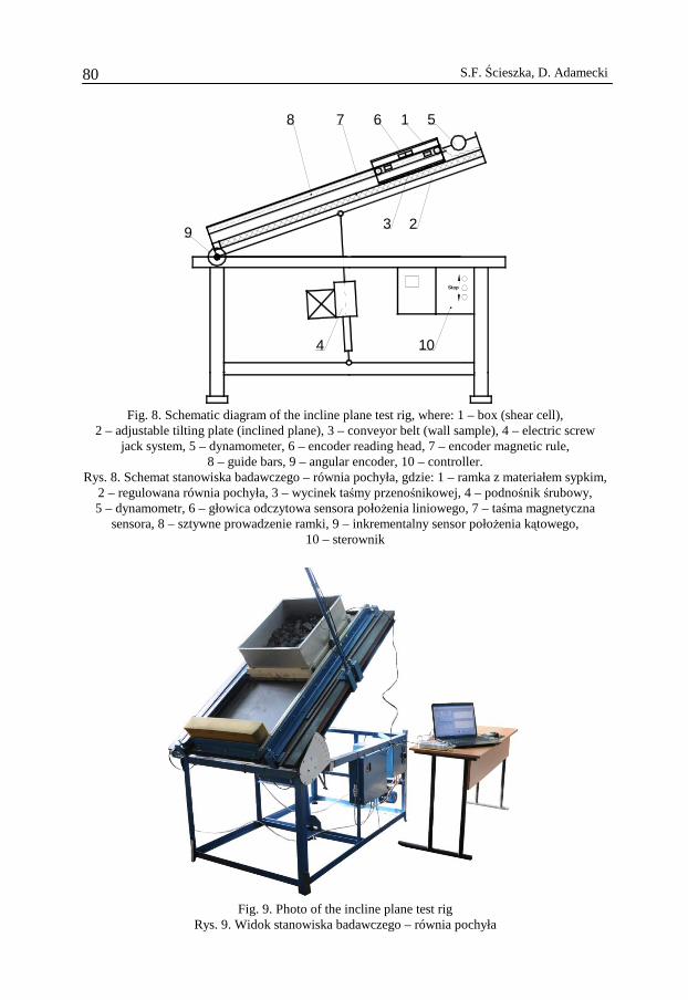
Fig. 9. Photo of the incline plane test rig
Rys. 9. Widok stanowiska badawczego – równia pochyła
Bulk solid stability on inclined belt conveyors 81
Tilting of the plate is stopped when ϕ reached the value ϕmax equal 34°, 36° or 38°. At the point of stoppage, ϕmax > ϕs and Fgm > 0 is always true. At this point the box is released from the strain gauge catch, and the box with the coal sample starts to skid along the belt. During the skid, the position of the box is read by the linear magnetic encoder and time is recorded. Then velocity, acceleration, friction force, and the kinetic coefficient of friction is calculated. The equations to calculate both coefficients of friction are as follow:
tancos
gm orn rS
n n
F Fm m
m m gµ ϕ
ϕ++= ⋅ −
⋅ ⋅ (10)
µs – coefficient of static friction, mn – mass of bulk solid sample, kg, mr – mass of box, kg, ϕ – angle of tilt, ϕs – angle of static friction (obtained from the linear equation y = Ax + B), Fgm – gravito-motive force, (for ϕ = ϕs, Fgm = 0), For – force of resistance to motion of the empty box, N.
maxmax max
tancos cos
n r ork
n n
m m Fa
m g m gµ ϕ
ϕ ϕ +
= ⋅ − − ⋅ ⋅ ⋅ (11)
µk – coefficient of kinetic friction, ϕmax – angle of tilt at which the box was released, a – acceleration of box with bulk solid skidding along the belt, m/s2.
Coal and rubber belt specimens
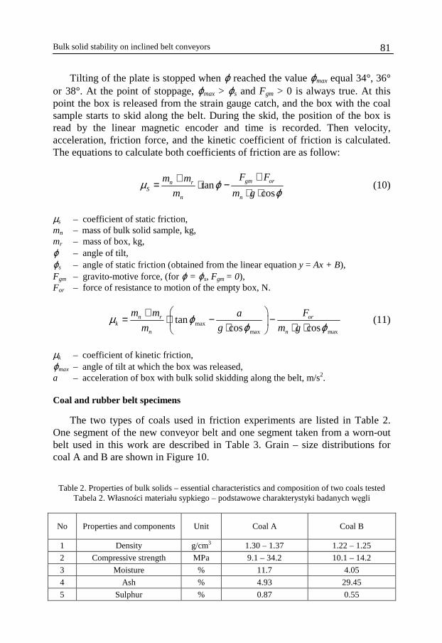
The two types of coals used in friction experiments are listed in Table 2. One segment of the new conveyor belt and one segment taken from a worn-out belt used in this work are described in Table 3. Grain – size distributions for coal A and B are shown in Figure 10.
Table 2. Properties of bulk solids – essential characteristics and composition of two coals tested
Tabela 2. Własności materiału sypkiego – podstawowe charakterystyki badanych węgli
No Properties and components Unit Coal A Coal B
1 Density g/cm3 1.30 – 1.37 1.22 – 1.25
2 Compressive strength MPa 9.1 – 34.2 10.1 – 14.2
3 Moisture % 11.7 4.05
4 Ash % 4.93 29.45
5 Sulphur % 0.87 0.55
S.F. Ścieszka, D. Adamecki 82
Table 3. Properties of conveyor belts – essential characteristics Tabela 3. Własności badanych taśm przenośnikowych
No Properties Unit Belt I new Belt II 1
type - Rubber with textile
reinforcement Rubber with textile
reinforcement 2 Shore hardness (A) - 72 63 3 Sa - Arithmetic Mean
Deviation of the Surface µm 1.36 8.61
4 Sz - Ten Point Height of the Surface
µm 56.7 73.7
5 St - Total height of the surface µm 66.4 146 6 Sdq - Root-Mean-Square
Slope of the Surface µm/µm 1.11 1.27
Fig. 10.Grain-size distributions for coal A and B
Rys. 10. Rozkład granulometryczny próbek węgli A i B
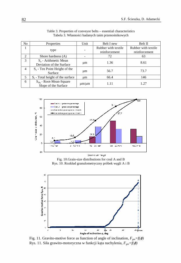
Fig. 11. Gravito-motive force as function of angle of inclination, Fgm=f(ϕ) Rys. 11. Siła grawito-motoryczna w funkcji kąta nachylenia, Fgm=f(ϕ)
Bulk solid stability on inclined belt conveyors 83
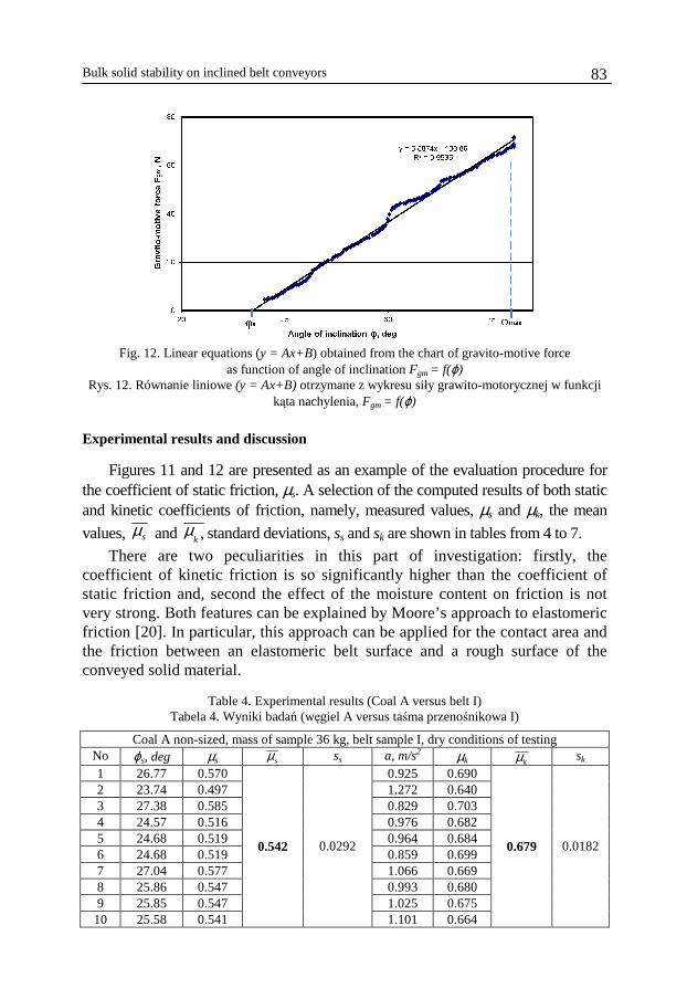
Fig. 12. Linear equations (y = Ax+B) obtained from the chart of gravito-motive force
as function of angle of inclination Fgm = f(ϕ) Rys. 12. Równanie liniowe (y = Ax+B) otrzymane z wykresu siły grawito-motorycznej w funkcji
kąta nachylenia, Fgm = f(ϕ)
Experimental results and discussion
Figures 11 and 12 are presented as an example of the evaluation procedure for the coefficient of static friction, µs. A selection of the computed results of both static and kinetic coefficients of friction, namely, measured values, µs and µk, the mean
values, sµ and ,kµ standard deviations, ss and sk are shown in tables from 4 to 7.
There are two peculiarities in this part of investigation: firstly, the coefficient of kinetic friction is so significantly higher than the coefficient of static friction and, second the effect of the moisture content on friction is not very strong. Both features can be explained by Moore’s approach to elastomeric friction [20]. In particular, this approach can be applied for the contact area and the friction between an elastomeric belt surface and a rough surface of the conveyed solid material.
Table 4. Experimental results (Coal A versus belt I)
Tabela 4. Wyniki badań (węgiel A versus taśma przenośnikowa I)
Coal A non-sized, mass of sample 36 kg, belt sample I, dry conditions of testing No ϕs, deg µs sµ ss a, m/s2 µk kµ sk 1 26.77 0.570 0.925 0.690 2 23.74 0.497 1.272 0.640 3 27.38 0.585 0.829 0.703 4 24.57 0.516 0.976 0.682 5 24.68 0.519 0.964 0.684 6 24.68 0.519 0.859 0.699 7 27.04 0.577 1.066 0.669 8 25.86 0.547 0.993 0.680 9 25.85 0.547 1.025 0.675 10 25.58 0.541
0.542 0.0292
1.101 0.664
0.679 0.0182
S.F. Ścieszka, D. Adamecki 84
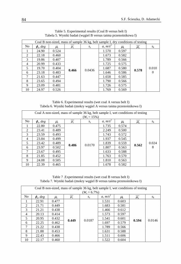
Table 5. Experimental results (Coal B versus belt I) Tabela 5. Wyniki badań (węgiel B versus taśma przenośnikowa I)
Coal B non-sized, mass of sample 36 kg, belt sample I, dry conditions of testing No ϕs, deg µs sµ ss a, m/s2 µk kµ sk 1 24.90 0.524 1.570 0.597 2 22.18 0.460 1.673 0.582 3 19.86 0.407 1.789 0.566 4 20.99 0.433 1.725 0.575 5 19.70 0.404 1.687 0.580 6 23.18 0.483 1.646 0.586 7 21.63 0.447 1.658 0.585 8 23.65 0.494 1.790 0.566 9 23.09 0.481 1.726 0.575 10 24.97 0.526
0.466 0.0436
1.769 0.569
0.578 0.010
0
Table 6. Experimental results (wet coal A versus belt I) Tabela 6. Wyniki badań (mokry węgiel A versus taśma przenośnikowa I)
Coal A non-sized, mass of sample 36 kg, belt sample I, wet conditions of testing (Wt = 15%)
No ϕs, deg µs sµ ss a, m/s2 µk kµ sk 1 22.80 0.475 1.735 0.574 2 23.41 0.489 2.249 0.500 3 23.59 0.493 1.743 0.572 4 23.84 0.499 1.937 0.545 5 23.42 0.489 1.839 0.559 6 23.97 0.502 1.807 0.563 7 23.67 0.495 1.633 0.588 8 21.85 0.452 1.763 0.570 9 24.08 0.505 1.810 0.563 10 22.39 0.465
0.486 0.0170
1.678 0.582
0.562 0.024
8
Table 7 .Experimental results (wet coal B versus belt I) Tabela 7. Wyniki badań (mokry węgiel B versus taśma przenośnikowa I)
Coal B non-sized, mass of sample 36 kg, belt sample I, wet conditions of testing (Wt = 6.7%)
No ϕs, deg µs sµ ss a, m/s2 µk kµ sk 1 22.91 0.477 1.531 0.603 2 21.71 0.449 1.683 0.581 3 21.21 0.438 1.466 0.612 4 20.13 0.414 1.573 0.597 5 20.95 0.432 1.541 0.601 6 22.25 0.462 1.697 0.579 7 21.22 0.438 1.789 0.566 8 21.88 0.453 1.631 0.588 9 22.43 0.466 1.511 0.606 10 22.17 0.460
0.449 0.0187
1.522 0.604
0.594 0.0146
Bulk solid stability on inclined belt conveyors 85
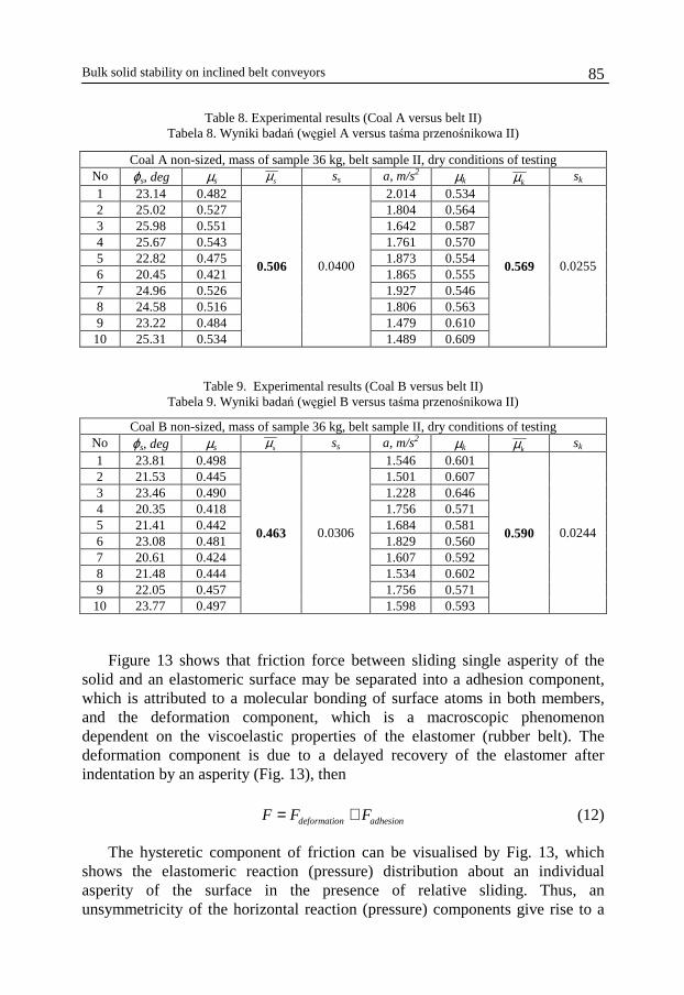
Table 8. Experimental results (Coal A versus belt II) Tabela 8. Wyniki badań (węgiel A versus taśma przenośnikowa II)
Coal A non-sized, mass of sample 36 kg, belt sample II, dry conditions of testing No ϕs, deg µs sµ ss a, m/s2 µk kµ sk 1 23.14 0.482 2.014 0.534 2 25.02 0.527 1.804 0.564 3 25.98 0.551 1.642 0.587 4 25.67 0.543 1.761 0.570 5 22.82 0.475 1.873 0.554 6 20.45 0.421 1.865 0.555 7 24.96 0.526 1.927 0.546 8 24.58 0.516 1.806 0.563 9 23.22 0.484 1.479 0.610 10 25.31 0.534
0.506 0.0400
1.489 0.609
0.569 0.0255
Table 9. Experimental results (Coal B versus belt II) Tabela 9. Wyniki badań (węgiel B versus taśma przenośnikowa II)
Coal B non-sized, mass of sample 36 kg, belt sample II, dry conditions of testing No ϕs, deg µs sµ ss a, m/s2 µk kµ sk 1 23.81 0.498 1.546 0.601 2 21.53 0.445 1.501 0.607 3 23.46 0.490 1.228 0.646 4 20.35 0.418 1.756 0.571 5 21.41 0.442 1.684 0.581 6 23.08 0.481 1.829 0.560 7 20.61 0.424 1.607 0.592 8 21.48 0.444 1.534 0.602 9 22.05 0.457 1.756 0.571 10 23.77 0.497
0.463 0.0306
1.598 0.593
0.590 0.0244
Figure 13 shows that friction force between sliding single asperity of the
solid and an elastomeric surface may be separated into a adhesion component, which is attributed to a molecular bonding of surface atoms in both members, and the deformation component, which is a macroscopic phenomenon dependent on the viscoelastic properties of the elastomer (rubber belt). The deformation component is due to a delayed recovery of the elastomer after indentation by an asperity (Fig. 13), then
deformation adhesionF F F= + (12)
The hysteretic component of friction can be visualised by Fig. 13, which shows the elastomeric reaction (pressure) distribution about an individual asperity of the surface in the presence of relative sliding. Thus, an unsymmetricity of the horizontal reaction (pressure) components give rise to a
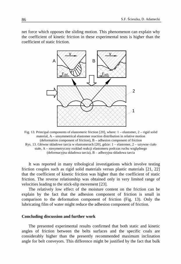
S.F. Ścieszka, D. Adamecki 86
net force which opposes the sliding motion. This phenomenon can explain why the coefficient of kinetic friction in these experimental tests is higher than the coefficient of static friction.
v
A B
v
Fdef. Fadh.
2
1
Fig. 13. Principal components of elastomeric friction [20], where: 1 – elastomer, 2 – rigid solid material, A – unsymmetrical elastomer reaction distribution in relative motion
(deformation component of friction), B – adhesion component of friction Rys. 13. Główne składowe tarcia w elastomerach [20], gdzie: 1 – elastomer, 2 – sztywne ciało
stałe, A – niesymetryczny rozkład reakcji elastomeru podczas ruchu względnego (deformacyjna składowa tarcia), B – adhezyjna składowa tarcia
It was reported in many tribological investigations which involve testing
friction couples such as rigid solid materials versus plastic materials [21, 22] that the coefficient of kinetic friction was higher than the coefficient of static friction. The reverse relationship was obtained only in very limited range of velocities leading to the stick-slip movement [23].
The relatively low effect of the moisture content on the friction can be explain by the fact that the adhesion component of friction is small in comparison to the deformation component of friction (Fig. 13). Only the lubricating film of water might reduce the adhesion component of friction.
Concluding discussion and further work
The presented experimental results confirmed that both static and kinetic angles of friction between the belts surfaces and the specific coals are considerably higher than the presently recommended maximum inclination angle for belt conveyors. This difference might be justified by the fact that bulk
Bulk solid stability on inclined belt conveyors 87
solid instability (e.g. its slip and spillage problems) on inclined belt conveyors depends on friction interactions which in turn are relative to dynamic phenomena, such as the belt vibration and flapping excited by belt sag and by idler eccentricity [17] during nominal working conditions, and the longitudinal stress wave movement launched along the belt on starting or stopping [18, 19] and by incorrect take up operation [19]. The investigation on belt vibration influence on bulk solid stability requires redesign of the existing rig used in the testing. The new rig with strictly controlled vibration of the belt is going to be used in the next step of testing.
Modification of the apparatus is necessary in order to simulate dynamic interaction between the belt and material and the dynamic agitation in the interface and to gain a more accurate friction characteristics representative of that observed practice. Further investigation into static and kinetic friction for a wider set of minerals and solid fuels in a wider range of conditions, including those with imposed vibrations, are needed. In particular, investigations on the influence of the angle of external friction on the maximum inclination angle of a conveyor are currently underway.
Industrial experience [5] and laboratory experiments [4] proved that, the longer the conveyor (time factor), the higher the conveyor speed (frequency factor), and the bigger the sag between the idlers (amplitude factor), the lower is the maximum angle of inclination. Additionally, as previously indicated, the angle is a functions of the external (wall) friction coefficient between the belt and the bulk material.
No two bulk materials are the same. No matter what type they are. This is the main reason why physical testing of a bulk solid is so important to proper design of bulk material handling systems. The cost of testing is a minor part of the overall cost of a material handling or conveying system. Having this data is one of the most important tools for trouble–shooting problems in the conveyor when raw materials change.
If an existing bulk solid conveying system works now, it should continue to work as long as the bulk solid stays the same and the conveyor does not suffer wear that changes its performance. But changes in the source of the coal (e.g. coal bed or colliery), or increased moisture, or changes in the process like increasing the speed of the belts can have consequences on the performance of a belt conveyor. When a bulk solid conveying system is being engineered, the bulk solids it will carry needs to be tested for frictional characteristics at the bulk solid and belt interface to achieve the overall performance required.
References
[1] Hartman H.L.: Introductory Mining Engineering, John Wiley & Sons, New York 1987. [2] Antoniak J.: Energy saving belt conveyors for surface a underground mining (in polish),
Wydawnictwo Politechniki Śląskiej, Gliwice 2010.
S.F. Ścieszka, D. Adamecki 88
[3] Gładysiewicz L.: Belt conveyors, theory and calculation (in polish), Wydawnictwo Politechniki Wrocławskiej, Wrocław 2003.
[4] Roberts A.W.: Bulk solid and conveyor belt interactions for efficient transportations without spillage, Bulk Solid Handling, vol. 18, no 1, 1998, pp. 49–57.
[5] Roberts A.W.: Bulk solid. An historical overview and current developments. Bulk Solid Handling, vol. 26, no 6, 2006, pp. 392–419.
[6] Kalman H., Rivkin M., Goder D.: The maximum inclination angle of a belt conveyor, Bulk Solid Handling, vol. 16, no 2, 1996, pp. 187–192.
[7] Conveyor Handbook, Fenner and Dunlop Publisher, Sydney, Australia 2009. [8] Belt Conveyor for Bulk Materials. CEMA. Publishing Co. Boston, USA 2006. [9] Kulinowski P., Kasza P., Zarzycki J., Furmanik K.: Tests of selected properties of excavated
materials having an influence on exploitation possibilities of a belt conveyor (in polish), Conference TUR, Cracow, 2007, pp. 541–552.
[10] Furmanik K.: The effect of frictional contact of transported material with the belt on operational capacity of belt conveyor (in polish), ZEM, vol. 42, 2007, pp. 7–21.
[11] Wheeler C., Roberts A.: Measurements of the main resistances of horizontal belt conveyors. Proc. International Conference. From Powder to Bulk, Institution of Mechanical Engineers. London, 2000, pp. 453–462.
[12] Trapp A.G. Energy saving troughing idler technology. Bulk Solid Handling, vol. 20, no 4, 2000, pp. 437–449.
[13] Jenike A.W.: Storage and flow of solids, Bulletin no 123, Engng. Exp. Station, University of Utah, Salt Lake City, 1964.
[14] Schulze D.: Powder and Bulk Solids – Behaviour, Characterization, Storage and flow. Springer. Berlin, 2008.
[15] Roberts A.W., Wiche S.J.: Prediction of lining wear life of bins and chutes in bulk solids handling operations, Tribology International, vol. 26, no 5, 1993.
[16] Pillai J.R., Bradley M., Berry R.: Comparison between the angles of wall friction measured on an on-line wall friction tester and the Jenike wall friction tester. Powder Technology, vol. 174, 2007, pp. 64–70.
[17] Harrison A.: Belt vibration and its influence on conveyor reliability, Bulk Solid Handling, vol. 14, 1994, pp. 723–727.
[18] Harrison A.: Modern belt take-ups and their dynamic motion. Bulk Solid Handling, vol. 12, no, 1992, pp. 581–584.
[19] Harrison A., Roberts A.W.: Technical requirements for operating conveyor belts at high speed, Bulk Solid Handling, vol. 4, no 1, 1984, pp. 99–104.
[20] Moore D.F.: The Friction and Lubrication of Elastomers, Pergamon Press, Oxford, 1972. [21] Ścieszka S.F.: A study of tribological phenomena in friction couple: brake composite
material – steel. ASLE Transaction, vol. 25, 1984, pp. 337–345. [22] Yamaguchi Y.: Tribology of Plastic Materials. Elsevier, Tokyo 1990. [23] Ścieszka S.F.: The importance of static friction characteristic of brake friction couple, and
methods of Testing, Tribotest, No 3, 1996, pp. 137–148.
Bulk solid stability on inclined belt conveyors 89
Stabilność strugi urobku na nachylonych przenośnikach taśmowych
S t r e s z c z e n i e
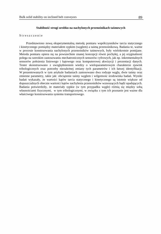
Przedstawiono nową eksperymentalną metodę pomiaru współczynników tarcia statycznego i kinetycznego pomiędzy materiałem sypkim (węglem) a taśmą przenośnikową. Badania te, ważne w procesie konstruowania nachylonych przenośników taśmowych, były wielokrotnie pomijane. Metoda pomiaru opiera się na powszechnie znanej koncepcji równi pochyłej, a jej oryginalność polega na szerokim zastosowaniu mechatronicznych sensorów cyfrowych, jak np. inkrementalnych sensorów położenia liniowego i kątowego oraz komputerowej akwizycji i prezentacji danych. Tester skonstruowano z uwzględnieniem wiedzy o wieloparametrowym charakterze zjawisk tribologicznych oraz potrzeby niezależnej zmiany tych parametrów i ich łatwej identyfikacji. W prezentowanych w tym artykule badaniach zastosowano dwa rodzaje węgla, dwie taśmy oraz zmienne parametry, takie jak: obciążenie taśmy węglem i wilgotność środowiska badań. Wyniki badań wykazały, że wartości kątów tarcia statycznego i kinetycznego są istotnie większe od dopuszczalnych obecnie wartości kątów nachylenia przenośników wznoszących bądź opadających. Badania potwierdziły, że materiały sypkie (w tym przypadku węgle) różnią się między sobą własnościami fizycznymi, w tym tribologicznymi, w związku z tym ich poznanie jest ważne dla właściwego konstruowania systemu transportowego.

S.F. Ścieszka, W. Grzegorzek, M. Żołnierz 90