Parallel Plate Particle Trapping with Application to Cantilevers
ARMTEC.COM
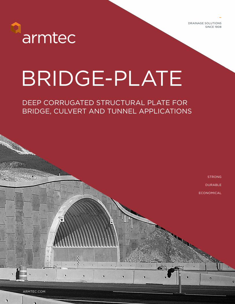
BRIDGE-PLATE
STRONG
DURABLE
ECONOMICAL
DEEP CORRUGATED STRUCTURAL PLATE FOR BRIDGE, CULVERT AND TUNNEL APPLICATIONS
–DRAINAGE SOLUTIONS
SINCE 1908
ARMTEC DRAINAGE SOLUTIONS | BRIDGE-PLATE PRODUCT GUIDE 32 VISIT ARMTEC.COM FOR MORE INFORMATION
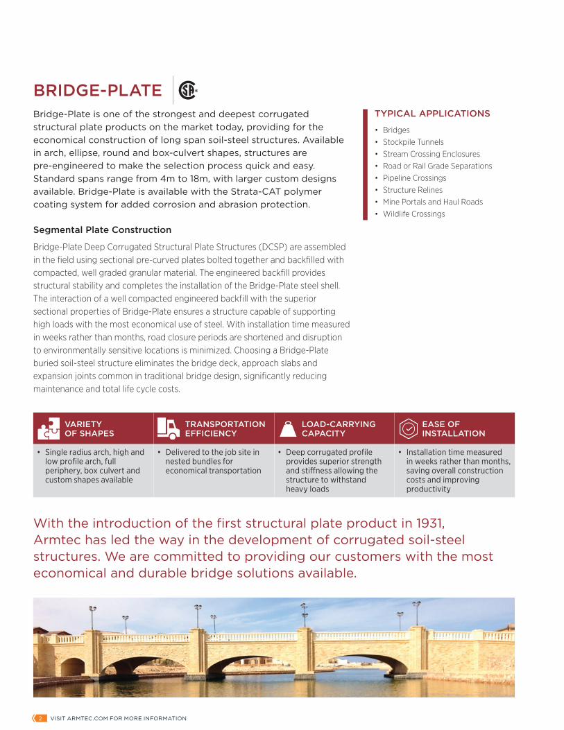
TYPICAL APPLICATIONS
• Bridges• Stockpile Tunnels• Stream Crossing Enclosures• Road or Rail Grade Separations• Pipeline Crossings• Structure Relines• Mine Portals and Haul Roads• Wildlife Crossings
BRIDGE-PLATEBridge-Plate is one of the strongest and deepest corrugated structural plate products on the market today, providing for the economical construction of long span soil-steel structures. Available in arch, ellipse, round and box-culvert shapes, structures are pre-engineered to make the selection process quick and easy. Standard spans range from 4m to 18m, with larger custom designs available. Bridge-Plate is available with the Strata-CAT polymer coating system for added corrosion and abrasion protection.
Segmental Plate Construction
Bridge-Plate Deep Corrugated Structural Plate Structures (DCSP) are assembled in the field using sectional pre-curved plates bolted together and backfilled with compacted, well graded granular material. The engineered backfill provides structural stability and completes the installation of the Bridge-Plate steel shell. The interaction of a well compacted engineered backfill with the superior sectional properties of Bridge-Plate ensures a structure capable of supporting high loads with the most economical use of steel. With installation time measured in weeks rather than months, road closure periods are shortened and disruption to environmentally sensitive locations is minimized. Choosing a Bridge-Plate buried soil-steel structure eliminates the bridge deck, approach slabs and expansion joints common in traditional bridge design, significantly reducing maintenance and total life cycle costs.
With the introduction of the first structural plate product in 1931, Armtec has led the way in the development of corrugated soil-steel structures. We are committed to providing our customers with the most economical and durable bridge solutions available.
VARIETY OF SHAPES
TRANSPORTATION EFFICIENCY
LOAD-CARRYING CAPACITY
EASE OF INSTALLATION
• Single radius arch, high and low profile arch, full periphery, box culvert and custom shapes available
• Delivered to the job site in nested bundles for economical transportation
• Deep corrugated profile provides superior strength and stiffness allowing the structure to withstand heavy loads
• Installation time measured in weeks rather than months, saving overall construction costs and improving productivity
ARMTEC DRAINAGE SOLUTIONS | BRIDGE-PLATE PRODUCT GUIDE 32 VISIT ARMTEC.COM FOR MORE INFORMATION
SHAPES
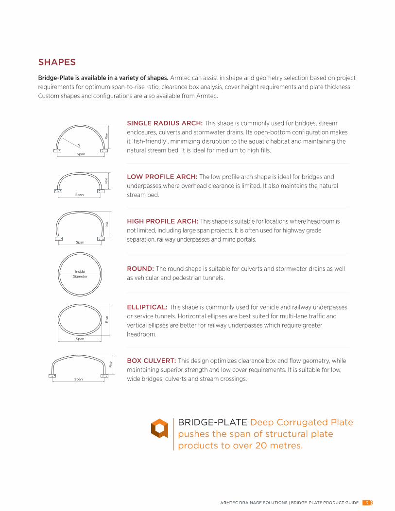
Bridge-Plate is available in a variety of shapes. Armtec can assist in shape and geometry selection based on project requirements for optimum span-to-rise ratio, clearance box analysis, cover height requirements and plate thickness. Custom shapes and configurations are also available from Armtec.
Ris
e
Span
Span
Span Span
Span
Span
Ris
e
InsideDiameter
R
Ris
e
Ris
e
Ris
e
Ris
e
Ris
e
Span
Span
Span Span
Span
Span
Ris
e
InsideDiameter
R
Ris
e
Ris
e
Ris
e
Ris
e
Ris
e
Span
Span
Span Span
Span
Span
Ris
e
InsideDiameter
R
Ris
e
Ris
e
Ris
e
Ris
e
Ris
e
Span
Span
Span Span
Span
Span
Ris
e
InsideDiameter
R
Ris
e
Ris
e
Ris
e
Ris
eRis
e
Span
Span
Span Span
Span
Span
Ris
e
InsideDiameter
R
Ris
e
Ris
e
Ris
e
Ris
e
SINGLE RADIUS ARCH: This shape is commonly used for bridges, stream enclosures, culverts and stormwater drains. Its open-bottom configuration makes it ‘fish-friendly’, minimizing disruption to the aquatic habitat and maintaining the natural stream bed. It is ideal for medium to high fills.
LOW PROFILE ARCH: The low profile arch shape is ideal for bridges and underpasses where overhead clearance is limited. It also maintains the natural stream bed.
HIGH PROFILE ARCH: This shape is suitable for locations where headroom is not limited, including large span projects. It is often used for highway grade separation, railway underpasses and mine portals.
ROUND: The round shape is suitable for culverts and stormwater drains as well as vehicular and pedestrian tunnels.
ELLIPTICAL: This shape is commonly used for vehicle and railway underpasses or service tunnels. Horizontal ellipses are best suited for multi-lane traffic and vertical ellipses are better for railway underpasses which require greater headroom.
BOX CULVERT: This design optimizes clearance box and flow geometry, while maintaining superior strength and low cover requirements. It is suitable for low, wide bridges, culverts and stream crossings.
BRIDGE-PLATE Deep Corrugated Plate pushes the span of structural plate products to over 20 metres.
Ris
e
Span
Span
Span Span
Span
Span
Ris
e
InsideDiameter
R
Ris
e
Ris
e
Ris
e
Ris
e
ARMTEC DRAINAGE SOLUTIONS | BRIDGE-PLATE PRODUCT GUIDE 54 VISIT ARMTEC.COM FOR MORE INFORMATION
BRIDGE-PLATE PROPERTIES
PLAN VIEW
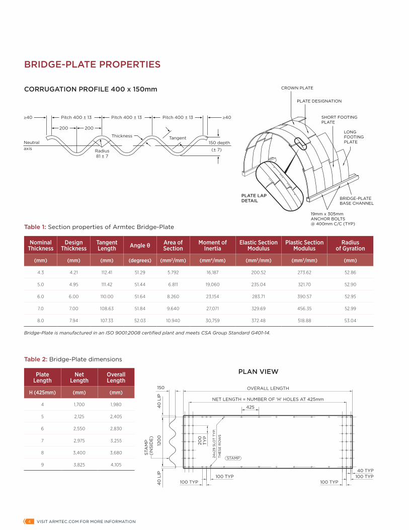
CORRUGATION PROFILE 400 x 150mm
Plate Length
Net Length
Overall Length
H (425mm) (mm) (mm)
4 1,700 1,980
5 2,125 2,405
6 2,550 2,830
7 2,975 3,255
8 3,400 3,680
9 3,825 4,105
Table 2: Bridge-Plate dimensions
PLATE DESIGNATION
19mm x 305mm ANCHOR BOLTS@ 400mm C/C (TYP)
BRIDGE-PLATEBASE CHANNEL
SHORT FOOTING PLATE
CROWN PLATE
LONG FOOTING PLATE
PLATE LAP DETAIL
Nominal Thickness
Design Thickness
Tangent Length Angle θ Area of
SectionMoment of
InertiaElastic Section
ModulusPlastic Section
ModulusRadius
of Gyration
(mm) (mm) (mm) (degrees) (mm2/mm) (mm4/mm) (mm3/mm) (mm3/mm) (mm)
4.3 4.21 112.41 51.29 5.792 16,187 200.52 273.62 52.86
5.0 4.95 111.42 51.44 6.811 19,060 235.04 321.70 52.90
6.0 6.00 110.00 51.64 8.260 23,154 283.71 390.57 52.95
7.0 7.00 108.63 51.84 9.640 27,071 329.69 456.35 52.99
8.0 7.94 107.33 52.03 10.940 30,759 372.48 518.88 53.04
Table 1: Section properties of Armtec Bridge-Plate
Bridge-Plate is manufactured in an ISO 9001:2008 certified plant and meets CSA Group Standard G401-14.
Rise
Span
SINGLE RADIUS ARCH
Span
Ris
e
R
ROUNDS
InsideDiameter
LOW-PROFILE ARCH
Ris
e
Span
Ris
e
Clearance Box
Span
HIGH-PROFILE ARCH
Rise
Span
BOX CULVERT
100 TYP40
LIP
STAMP
100 TYP
OVERALL LENGTH
NET LENGTH = NUMBER OF 'H' HOLES AT 425mm
24x2
9 S
LOT
TY
P.
TH
ES
E R
OW
S
200
TY
P
120
04
0 L
IP
STA
MP
(IN
SID
E)
150
100 TYP100 TYP40 TYP
425
PLAN AND SECTION VIEW
30
of Bolt
175
88 87
180
150
c
of Boltc
Span
Rise
Height of cover
≥40
Neutralaxis
≥40Pitch 400 ± 13
200 200
Pitch 400 ± 13
Radius81 ± 7
Thickness Tangent150 depth
Pitch 400 ± 13
(± 7)
ARMTEC DRAINAGE SOLUTIONS | BRIDGE-PLATE PRODUCT GUIDE 54 VISIT ARMTEC.COM FOR MORE INFORMATION
DESIGN STANDARD
Structural Design
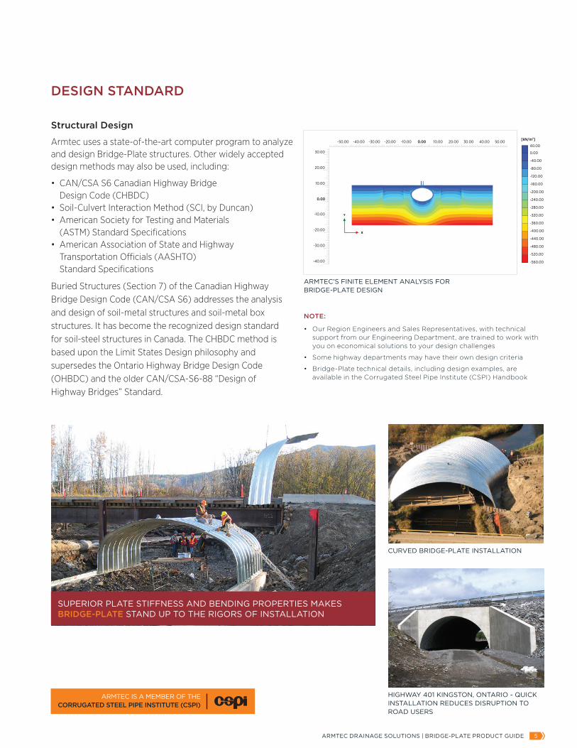
Armtec uses a state-of-the-art computer program to analyze and design Bridge-Plate structures. Other widely accepted design methods may also be used, including:
• CAN/CSA S6 Canadian Highway Bridge Design Code (CHBDC)• Soil-Culvert Interaction Method (SCI, by Duncan)• American Society for Testing and Materials (ASTM) Standard Specifications• American Association of State and Highway Transportation Officials (AASHTO) Standard Specifications
Buried Structures (Section 7) of the Canadian Highway Bridge Design Code (CAN/CSA S6) addresses the analysis and design of soil-metal structures and soil-metal box structures. It has become the recognized design standard for soil-steel structures in Canada. The CHBDC method is based upon the Limit States Design philosophy and supersedes the Ontario Highway Bridge Design Code (OHBDC) and the older CAN/CSA-S6-88 “Design of Highway Bridges” Standard.
HIGHWAY 401 KINGSTON, ONTARIO - QUICK INSTALLATION REDUCES DISRUPTION TO ROAD USERS
CURVED BRIDGE-PLATE INSTALLATION
NOTE:
• Our Region Engineers and Sales Representatives, with technical support from our Engineering Department, are trained to work with you on economical solutions to your design challenges
• Some highway departments may have their own design criteria
• Bridge-Plate technical details, including design examples, are available in the Corrugated Steel Pipe Institute (CSPI) Handbook
ARMTEC IS A MEMBER OF THE CORRUGATED STEEL PIPE INSTITUTE (CSPI)
SUPERIOR PLATE STIFFNESS AND BENDING PROPERTIES MAKES BRIDGE-PLATE STAND UP TO THE RIGORS OF INSTALLATION
[kN/m2]
-560.00
-520.00
-480.00
-440.00
-400.00
-360.00
-320.00
-280.00
-240.00
-200.00
-160.00
-120.00
-80.00
-40.00
0.00
40.00-50.00 -40.00 -30.00 -20.00 -10.00 0.00 10.00 20.00 30.00 40.00 50.00
-40.00
-30.00
-20.00
-10.00
0.00
10.00
20.00
30.00
ARMTEC’S FINITE ELEMENT ANALYSIS FORBRIDGE-PLATE DESIGN
ARMTEC DRAINAGE SOLUTIONS | BRIDGE-PLATE PRODUCT GUIDE 76 VISIT ARMTEC.COM FOR MORE INFORMATION
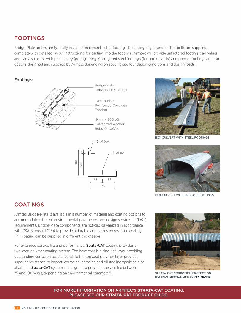
FOOTINGS
Bridge-Plate arches are typically installed on concrete strip footings. Receiving angles and anchor bolts are supplied, complete with detailed layout instructions, for casting into the footings. Armtec will provide unfactored footing load values and can also assist with preliminary footing sizing. Corrugated steel footings (for box culverts) and precast footings are also options designed and supplied by Armtec depending on specific site foundation conditions and design loads.
COATINGS
Armtec Bridge-Plate is available in a number of material and coating options to accommodate different environmental parameters and design service life (DSL) requirements. Bridge-Plate components are hot-dip galvanized in accordance with CSA Standard G164 to provide a durable and corrosion resistant coating. This coating can be supplied in different thicknesses.
For extended service life and performance, Strata-CAT coating provides a two-coat polymer coating system. The base coat is a zinc-rich layer providing outstanding corrosion resistance while the top coat polymer layer provides superior resistance to impact, corrosion, abrasion and diluted inorganic acid or alkali. The Strata-CAT system is designed to provide a service life between 75 and 100 years, depending on environmental parameters.
Rise
Span
SINGLE RADIUS ARCH
Span
Ris
e
R
ROUNDS
InsideDiameter
LOW-PROFILE ARCH
Ris
eSpan
Ris
e
Clearance Box
Span
HIGH-PROFILE ARCH
Rise
Span
BOX CULVERT
100 TYP40
LIP
STAMP
100 TYP
OVERALL LENGTH
NET LENGTH = NUMBER OF 'H' HOLES AT 425mm
24x2
9 S
LOT
TY
P.
TH
ES
E R
OW
S
200
TY
P
120
04
0 L
IP
STA
MP
(IN
SID
E)
150
100 TYP100 TYP40 TYP
425
PLAN AND SECTION VIEW
30
of Bolt
175
88 87
180
150
c
of Boltc
Span
Rise
Height of cover
Footings:
BOX CULVERT WITH STEEL FOOTINGS
BOX CULVERT WITH PRECAST FOOTINGS
STRATA-CAT CORROSION PROTECTION EXTENDS SERVICE LIFE TO 75+ YEARS
FOR MORE INFORMATION ON ARMTEC’S STRATA-CAT COATING, PLEASE SEE OUR STRATA-CAT PRODUCT GUIDE.
ARMTEC DRAINAGE SOLUTIONS | BRIDGE-PLATE PRODUCT GUIDE 76 VISIT ARMTEC.COM FOR MORE INFORMATION
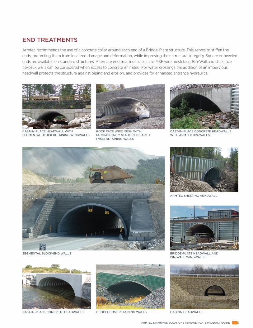
END TREATMENTS
Armtec recommends the use of a concrete collar around each end of a Bridge-Plate structure. This serves to stiffen the ends, protecting them from localized damage and deformation, while improving their structural integrity. Square or beveled ends are available on standard structures. Alternate end treatments, such as MSE wire mesh face, Bin-Wall and steel face tie-back walls can be considered when access to concrete is limited. For water crossings the addition of an impervious headwall protects the structure against piping and erosion, and provides for enhanced entrance hydraulics.
CAST-IN-PLACE CONCRETE HEADWALLS WITH ARMTEC BIN-WALLS
ROCK FACE WIRE MESH WITH MECHANICALLY STABILIZED EARTH (MSE) RETAINING WALLS
CAST-IN-PLACE HEADWALL WITH SEGMENTAL BLOCK RETAINING WINGWALLS
SEGMENTAL BLOCK-END WALLS
ARMTEC SHEETING HEADWALL
BRIDGE-PLATE HEADWALL AND BIN-WALL WINGWALLS
GABION HEADWALLSCAST-IN-PLACE CONCRETE HEADWALLS GEOCELL MSE RETAINING WALLS
FOR MORE INFORMATION ON ARMTEC’S STRATA-CAT COATING, PLEASE SEE OUR STRATA-CAT PRODUCT GUIDE.
ARMTEC DRAINAGE SOLUTIONS | BRIDGE-PLATE PRODUCT GUIDE 98 VISIT ARMTEC.COM FOR MORE INFORMATION
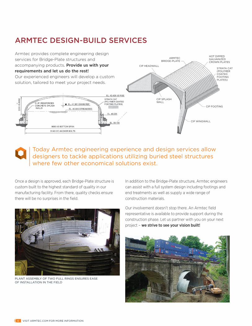
CIP HEADWALL
CIP SPLASH WALL
CIP WINGWALL
CIP FOOTING
HOT DIPPED GALVANIZED CROWN PLATES
STRATA CAT (POLYMER COATED FOOTING PLATES)
ARMTEC BRIDGE-PLATE
ARMTEC DESIGN-BUILD SERVICES
Armtec provides complete engineering design services for Bridge-Plate structures and accompanying products. Provide us with your requirements and let us do the rest! Our experienced engineers will develop a custom solution, tailored to meet your project needs.
In addition to the Bridge-Plate structure, Armtec engineers can assist with a full system design including footings and end treatments as well as supply a wide range of construction materials.
Our involvement doesn’t stop there. An Armtec field representative is available to provide support during the construction phase. Let us partner with you on your next project – we strive to see your vision built!
Once a design is approved, each Bridge-Plate structure is custom built to the highest standard of quality in our manufacturing facility. From there, quality checks ensure there will be no surprises in the field.
PLANT ASSEMBLY OF TWO FULL RINGS ENSURES EASE OF INSTALLATION IN THE FIELD
Today Armtec engineering experience and design services allow designers to tackle applications utilizing buried steel structures where few other economical solutions exist.
ARMTEC DRAINAGE SOLUTIONS | BRIDGE-PLATE PRODUCT GUIDE 98 VISIT ARMTEC.COM FOR MORE INFORMATION
BRIDGE-PLATE INSTALLATION TIME IS MEASURED IN WEEKS RATHER THAN MONTHS
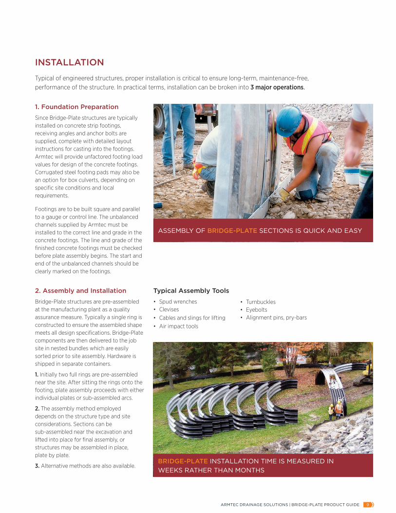
1. Foundation Preparation
Since Bridge-Plate structures are typically installed on concrete strip footings, receiving angles and anchor bolts are supplied, complete with detailed layout instructions for casting into the footings. Armtec will provide unfactored footing load values for design of the concrete footings. Corrugated steel footing pads may also be an option for box culverts, depending on specific site conditions and local requirements.
Footings are to be built square and parallel to a gauge or control line. The unbalanced channels supplied by Armtec must be installed to the correct line and grade in the concrete footings. The line and grade of the finished concrete footings must be checked before plate assembly begins. The start and end of the unbalanced channels should be clearly marked on the footings.
INSTALLATION
Typical of engineered structures, proper installation is critical to ensure long-term, maintenance-free, performance of the structure. In practical terms, installation can be broken into 3 major operations.
2. Assembly and Installation
Bridge-Plate structures are pre-assembled at the manufacturing plant as a quality assurance measure. Typically a single ring is constructed to ensure the assembled shape meets all design specifications. Bridge-Plate components are then delivered to the job site in nested bundles which are easily sorted prior to site assembly. Hardware is shipped in separate containers.
1. Initially two full rings are pre-assembled near the site. After sitting the rings onto the footing, plate assembly proceeds with either individual plates or sub-assembled arcs.
2. The assembly method employed depends on the structure type and site considerations. Sections can be sub-assembled near the excavation and lifted into place for final assembly, or structures may be assembled in place, plate by plate.
3. Alternative methods are also available.
Typical Assembly Tools
• Spud wrenches• Clevises• Cables and slings for lifting• Air impact tools
• Turnbuckles• Eyebolts• Alignment pins, pry-bars
ASSEMBLY OF BRIDGE-PLATE SECTIONS IS QUICK AND EASY
ARMTEC DRAINAGE SOLUTIONS | BRIDGE-PLATE PRODUCT GUIDE 1110 VISIT ARMTEC.COM FOR MORE INFORMATION
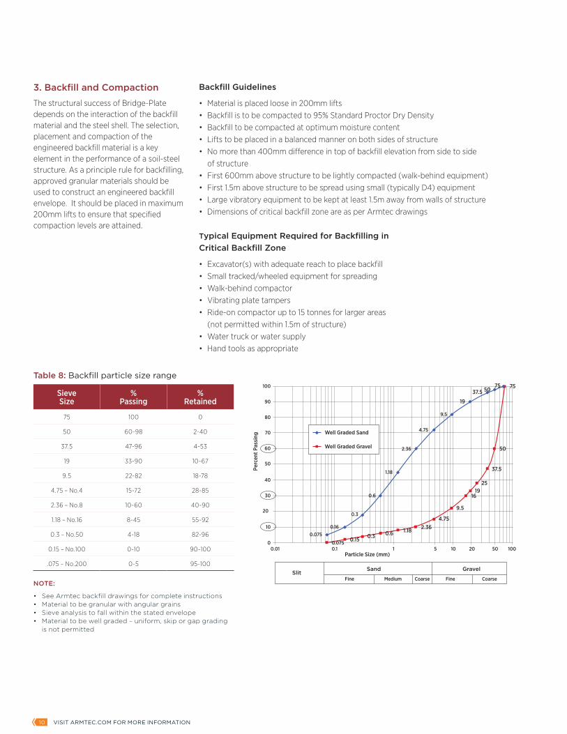
3. Backfill and Compaction
The structural success of Bridge-Plate depends on the interaction of the backfill material and the steel shell. The selection, placement and compaction of the engineered backfill material is a key element in the performance of a soil-steel structure. As a principle rule for backfilling, approved granular materials should be used to construct an engineered backfill envelope. It should be placed in maximum 200mm lifts to ensure that specified compaction levels are attained.
Backfill Guidelines
• Material is placed loose in 200mm lifts• Backfill is to be compacted to 95% Standard Proctor Dry Density• Backfill to be compacted at optimum moisture content• Lifts to be placed in a balanced manner on both sides of structure• No more than 400mm difference in top of backfill elevation from side to side of structure• First 600mm above structure to be lightly compacted (walk-behind equipment)• First 1.5m above structure to be spread using small (typically D4) equipment• Large vibratory equipment to be kept at least 1.5m away from walls of structure• Dimensions of critical backfill zone are as per Armtec drawings
Typical Equipment Required for Backfilling in Critical Backfill Zone
• Excavator(s) with adequate reach to place backfill• Small tracked/wheeled equipment for spreading• Walk-behind compactor• Vibrating plate tampers• Ride-on compactor up to 15 tonnes for larger areas (not permitted within 1.5m of structure)• Water truck or water supply• Hand tools as appropriate
NOTE:
• See Armtec backfill drawings for complete instructions• Material to be granular with angular grains• Sieve analysis to fall within the stated envelope• Material to be well graded – uniform, skip or gap grading is not permitted
Sieve Size
% Passing
% Retained
75 100 0
50 60-98 2-40
37.5 47-96 4-53
19 33-90 10-67
9.5 22-82 18-78
4.75 – No.4 15-72 28-85
2.36 – No.8 10-60 40-90
1.18 – No.16 8-45 55-92
0.3 – No.50 4-18 82-96
0.15 – No.100 0-10 90-100
.075 – No.200 0-5 95-100
Table 8: Backfill particle size range
SlitSand Gravel
Fine CoarseCoarseMediumFine
100
90
80
70
60
50
40
30
20
10
00.01
0.0750.16
0.1 1 105Particle Size (mm)
Perc
ent P
assi
ng
20 50 100
0.3
Well Graded Sand
Well Graded Gravel
0.6
1.18
2.36
4.75
9.5
19
37.5 5075 75
50
37.5
2519
16
9.5
4.752.361.180.60.30.15
0.075
ARMTEC DRAINAGE SOLUTIONS | BRIDGE-PLATE PRODUCT GUIDE 1110 VISIT ARMTEC.COM FOR MORE INFORMATION
Ris
e
Span
Span
Span
Clearance Box
Span
Span
Span
Ris
e
InsideDiameter
R
Ris
e
Ris
e
Ris
e
Ris
e HaunchRadius
Side Angle
CrownRadius
CrownAngle Leg Length
HaunchAngleR
S
R T
R B
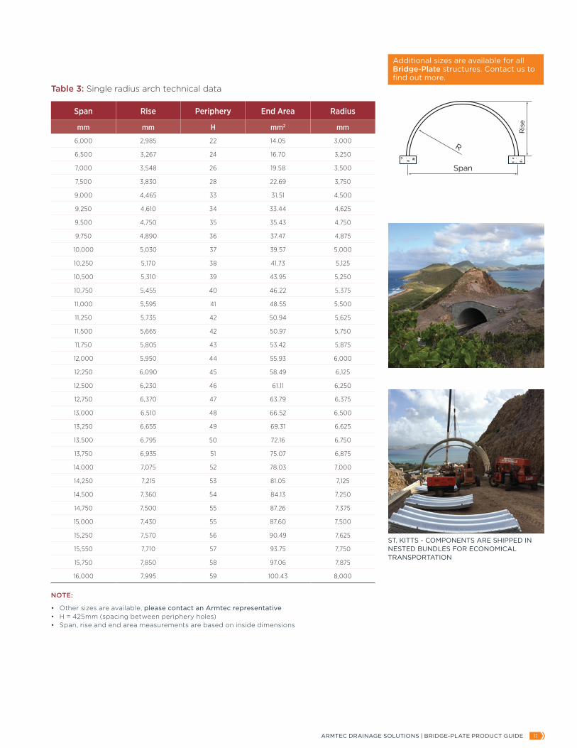
Span Rise Periphery End Area Radius
mm mm H mm2 mm
6,000 2,985 22 14.05 3,000
6,500 3,267 24 16.70 3,250
7,000 3,548 26 19.58 3,500
7,500 3,830 28 22.69 3,750
9,000 4,465 33 31.51 4,500
9,250 4,610 34 33.44 4,625
9,500 4,750 35 35.43 4,750
9,750 4,890 36 37.47 4,875
10,000 5,030 37 39.57 5,000
10,250 5,170 38 41.73 5,125
10,500 5,310 39 43.95 5,250
10,750 5,455 40 46.22 5,375
11,000 5,595 41 48.55 5,500
11,250 5,735 42 50.94 5,625
11,500 5,665 42 50.97 5,750
11,750 5,805 43 53.42 5,875
12,000 5,950 44 55.93 6,000
12,250 6,090 45 58.49 6,125
12,500 6,230 46 61.11 6,250
12,750 6,370 47 63.79 6,375
13,000 6,510 48 66.52 6,500
13,250 6,655 49 69.31 6,625
13,500 6,795 50 72.16 6,750
13,750 6,935 51 75.07 6,875
14,000 7,075 52 78.03 7,000
14,250 7,215 53 81.05 7,125
14,500 7,360 54 84.13 7,250
14,750 7,500 55 87.26 7,375
15,000 7,430 55 87.60 7,500
15,250 7,570 56 90.49 7,625
15,550 7,710 57 93.75 7,750
15,750 7,850 58 97.06 7,875
16,000 7,995 59 100.43 8,000
Table 3: Single radius arch technical data
NOTE:
• Other sizes are available, please contact an Armtec representative• H = 425mm (spacing between periphery holes)• Span, rise and end area measurements are based on inside dimensions
ST. KITTS - COMPONENTS ARE SHIPPED IN NESTED BUNDLES FOR ECONOMICAL TRANSPORTATION
Additional sizes are available for all Bridge-Plate structures. Contact us to find out more.
ARMTEC DRAINAGE SOLUTIONS | BRIDGE-PLATE PRODUCT GUIDE 1312 VISIT ARMTEC.COM FOR MORE INFORMATION
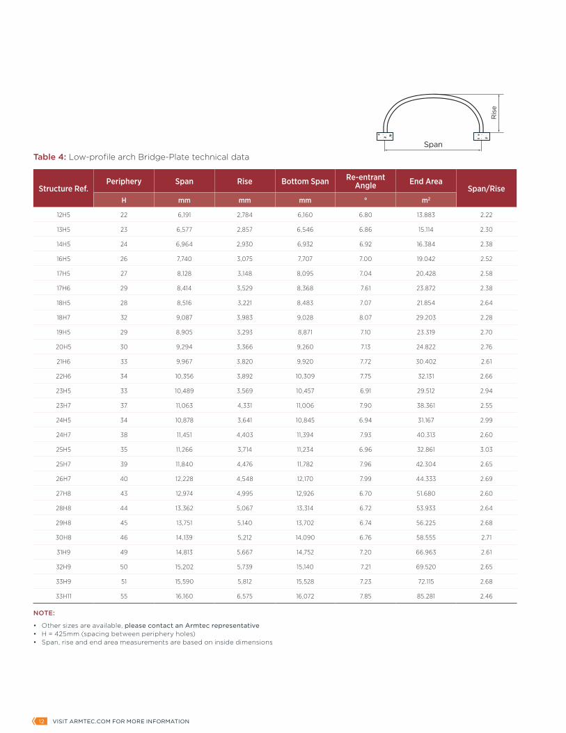
Structure Ref.Periphery Span Rise Bottom Span Re-entrant
Angle End AreaSpan/Rise
H mm mm mm ° m2
12H5 22 6,191 2,784 6,160 6.80 13.883 2.22
13H5 23 6,577 2,857 6,546 6.86 15.114 2.30
14H5 24 6,964 2,930 6,932 6.92 16.384 2.38
16H5 26 7,740 3,075 7,707 7.00 19.042 2.52
17H5 27 8,128 3,148 8,095 7.04 20.428 2.58
17H6 29 8,414 3,529 8,368 7.61 23.872 2.38
18H5 28 8,516 3,221 8,483 7.07 21.854 2.64
18H7 32 9,087 3,983 9,028 8.07 29.203 2.28
19H5 29 8,905 3,293 8,871 7.10 23.319 2.70
20H5 30 9,294 3,366 9,260 7.13 24.822 2.76
21H6 33 9,967 3,820 9,920 7.72 30.402 2.61
22H6 34 10,356 3,892 10,309 7.75 32.131 2.66
23H5 33 10,489 3,569 10,457 6.91 29.512 2.94
23H7 37 11,063 4,331 11,006 7.90 38.361 2.55
24H5 34 10,878 3,641 10,845 6.94 31.167 2.99
24H7 38 11,451 4,403 11,394 7.93 40.313 2.60
25H5 35 11,266 3,714 11,234 6.96 32.861 3.03
25H7 39 11,840 4,476 11,782 7.96 42.304 2.65
26H7 40 12,228 4,548 12,170 7.99 44.333 2.69
27H8 43 12,974 4,995 12,926 6.70 51.680 2.60
28H8 44 13,362 5,067 13,314 6.72 53.933 2.64
29H8 45 13,751 5,140 13,702 6.74 56.225 2.68
30H8 46 14,139 5,212 14,090 6.76 58.555 2.71
31H9 49 14,813 5,667 14,752 7.20 66.963 2.61
32H9 50 15,202 5,739 15,140 7.21 69.520 2.65
33H9 51 15,590 5,812 15,528 7.23 72.115 2.68
33H11 55 16,160 6,575 16,072 7.85 85.281 2.46
NOTE:
• Other sizes are available, please contact an Armtec representative• H = 425mm (spacing between periphery holes)• Span, rise and end area measurements are based on inside dimensions
Table 4: Low-profile arch Bridge-Plate technical data
Ris
e
Span
Span
Span
Clearance Box
Span
Span
Span
Ris
e
InsideDiameter
R
Ris
e
Ris
e
Ris
e
Ris
e HaunchRadius
Side Angle
CrownRadius
CrownAngle Leg Length
HaunchAngleR
S
R T
R B
ARMTEC DRAINAGE SOLUTIONS | BRIDGE-PLATE PRODUCT GUIDE 1312 VISIT ARMTEC.COM FOR MORE INFORMATION
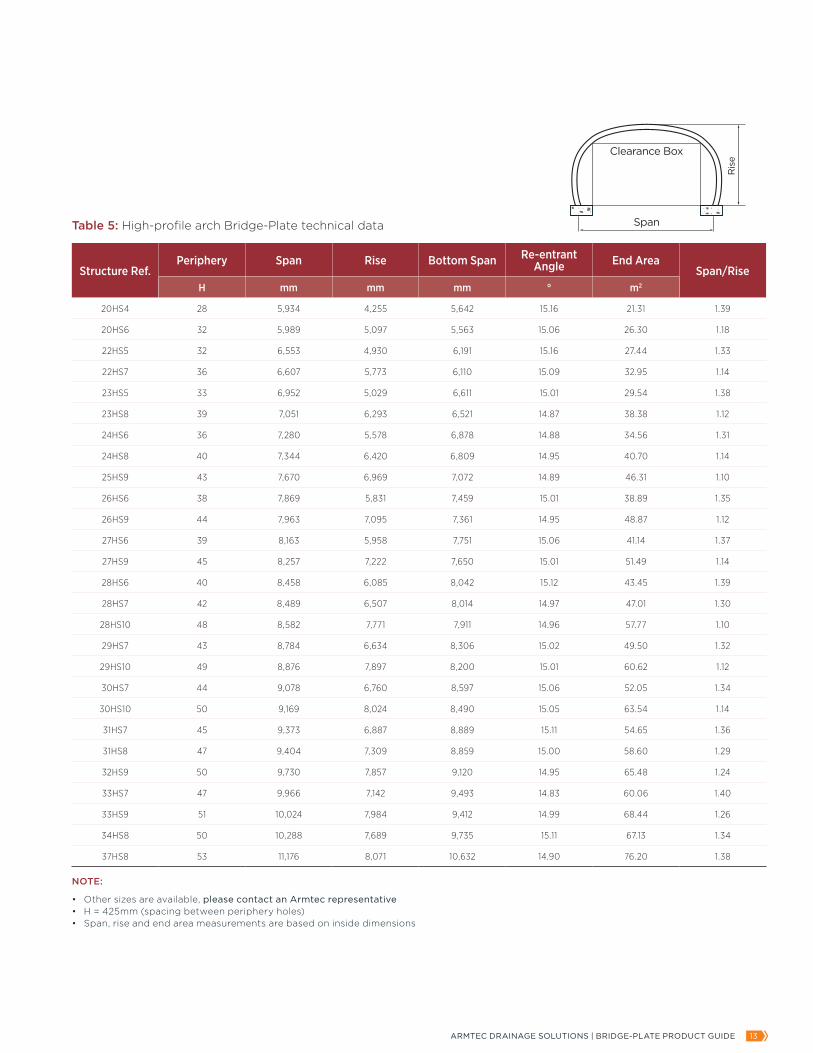
Structure Ref.Periphery Span Rise Bottom Span Re-entrant
Angle End AreaSpan/Rise
H mm mm mm ° m2
20HS4 28 5,934 4,255 5,642 15.16 21.31 1.39
20HS6 32 5,989 5,097 5,563 15.06 26.30 1.18
22HS5 32 6,553 4,930 6,191 15.16 27.44 1.33
22HS7 36 6,607 5,773 6,110 15.09 32.95 1.14
23HS5 33 6,952 5,029 6,611 15.01 29.54 1.38
23HS8 39 7,051 6,293 6,521 14.87 38.38 1.12
24HS6 36 7,280 5,578 6,878 14.88 34.56 1.31
24HS8 40 7,344 6,420 6,809 14.95 40.70 1.14
25HS9 43 7,670 6,969 7,072 14.89 46.31 1.10
26HS6 38 7,869 5,831 7,459 15.01 38.89 1.35
26HS9 44 7,963 7,095 7,361 14.95 48.87 1.12
27HS6 39 8,163 5,958 7,751 15.06 41.14 1.37
27HS9 45 8,257 7,222 7,650 15.01 51.49 1.14
28HS6 40 8,458 6,085 8,042 15.12 43.45 1.39
28HS7 42 8,489 6,507 8,014 14.97 47.01 1.30
28HS10 48 8,582 7,771 7,911 14.96 57.77 1.10
29HS7 43 8,784 6,634 8,306 15.02 49.50 1.32
29HS10 49 8,876 7,897 8,200 15.01 60.62 1.12
30HS7 44 9,078 6,760 8,597 15.06 52.05 1.34
30HS10 50 9,169 8,024 8,490 15.05 63.54 1.14
31HS7 45 9,373 6,887 8,889 15.11 54.65 1.36
31HS8 47 9,404 7,309 8,859 15.00 58.60 1.29
32HS9 50 9,730 7,857 9,120 14.95 65.48 1.24
33HS7 47 9,966 7,142 9,493 14.83 60.06 1.40
33HS9 51 10,024 7,984 9,412 14.99 68.44 1.26
34HS8 50 10,288 7,689 9,735 15.11 67.13 1.34
37HS8 53 11,176 8,071 10,632 14.90 76.20 1.38
NOTE:
• Other sizes are available, please contact an Armtec representative• H = 425mm (spacing between periphery holes)• Span, rise and end area measurements are based on inside dimensions
Table 5: High-profile arch Bridge-Plate technical data
Ris
e
Span
Span
Span
Clearance Box
Span
Span
Span
Ris
e
InsideDiameter
R
Ris
e
Ris
e
Ris
e
Ris
e HaunchRadius
Side Angle
CrownRadius
CrownAngle Leg Length
HaunchAngleR
S
R T
R B
ARMTEC DRAINAGE SOLUTIONS | BRIDGE-PLATE PRODUCT GUIDE 1514 VISIT ARMTEC.COM FOR MORE INFORMATION
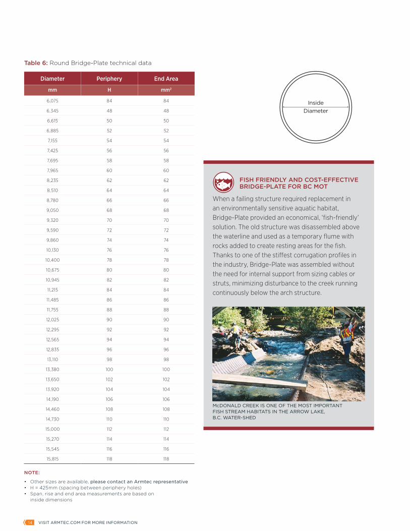
Diameter Periphery End Area
mm H mm2
6,075 84 84
6,345 48 48
6,615 50 50
6,885 52 52
7,155 54 54
7,425 56 56
7,695 58 58
7,965 60 60
8,235 62 62
8,510 64 64
8,780 66 66
9,050 68 68
9,320 70 70
9,590 72 72
9,860 74 74
10,130 76 76
10,400 78 78
10,675 80 80
10,945 82 82
11,215 84 84
11,485 86 86
11,755 88 88
12,025 90 90
12,295 92 92
12,565 94 94
12,835 96 96
13,110 98 98
13,380 100 100
13,650 102 102
13,920 104 104
14,190 106 106
14,460 108 108
14,730 110 110
15,000 112 112
15,270 114 114
15,545 116 116
15,815 118 118
Table 6: Round Bridge-Plate technical data
Ris
e
Span
Span
Span
Clearance Box
Span
Span
Span
Ris
e
InsideDiameter
R
Ris
e
Ris
e
Ris
e
Ris
e HaunchRadius
Side Angle
CrownRadius
CrownAngle Leg Length
HaunchAngleR
S
R T
R B
NOTE:
• Other sizes are available, please contact an Armtec representative• H = 425mm (spacing between periphery holes)• Span, rise and end area measurements are based on inside dimensions
FISH FRIENDLY
FISH FRIENDLY
FISH FRIENDLY AND COST-EFFECTIVE BRIDGE-PLATE FOR BC MOT
When a failing structure required replacement in an environmentally sensitive aquatic habitat, Bridge-Plate provided an economical, ‘fish-friendly’ solution. The old structure was disassembled above the waterline and used as a temporary flume with rocks added to create resting areas for the fish. Thanks to one of the stiffest corrugation profiles in the industry, Bridge-Plate was assembled without the need for internal support from sizing cables or struts, minimizing disturbance to the creek running continuously below the arch structure.
McDONALD CREEK IS ONE OF THE MOST IMPORTANT FISH STREAM HABITATS IN THE ARROW LAKE, B.C. WATER-SHED
ARMTEC DRAINAGE SOLUTIONS | BRIDGE-PLATE PRODUCT GUIDE 1514 VISIT ARMTEC.COM FOR MORE INFORMATION
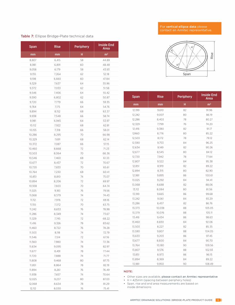
Span Rise Periphery Inside EndArea
mm mm H m2
12,199 9,610 82 91.96
12,242 9,007 80 86.19
12,286 8,403 78 80.27
12,329 7,799 76 74.20
12,416 9,380 82 91.17
12460 8,776 80 85.22
12,503 8,172 78 79.12
12,590 9,753 84 96.25
12,634 9,149 82 90.26
12,677 8,545 80 84.12
12,720 7,942 78 77.84
12,807 9,522 84 95.38
12,851 8,919 82 89.22
12,894 8,315 80 82.90
12,981 9,895 86 100.61
13,025 9,292 84 94.41
13,068 8,688 82 88.06
13,112 8,084 80 81.56
13,199 9,665 86 99.68
13,242 9,061 84 93.29
13,286 8,457 82 86.76
13,373 10,038 88 105.05
13,379 10,076 88 105.11
13,416 9,434 86 98.63
13,460 8,830 84 92.06
13,503 8,227 82 85.35
13,590 9,807 88 104.05
13,633 9,203 86 97.45
13,677 8,600 84 90.70
13,764 10,180 90 109.56
13,807 9,576 88 102.93
13,851 8,973 86 96.15
13,894 8,369 84 89.22
13,981 9,950 90 108.49
NOTE:
• Other sizes are available, please contact an Armtec representative• H = 425mm (spacing between periphery holes)• Span, rise and end area measurements are based on inside dimensions
Span Rise Periphery Inside EndArea
mm mm H m2
8,807 6,415 58 44.89
8,981 6,891 60 48.48
9,058 6,179 58 43.93
9,155 7,264 62 52.18
9,198 6,660 60 47.84
9,329 7,637 64 55.96
9,372 7,033 62 51.58
9,546 7,406 64 55.42
9,590 6,802 62 50.87
9,720 7,779 66 59.35
9,764 7,175 64 54.76
9,894 8,152 68 63.37
9,938 7,548 66 58.74
9,981 6,945 64 53.97
10,112 7,922 68 62.81
10,155 7,318 66 58.01
10,286 8,295 70 66.98
10,329 7,691 68 62.14
10,372 7,087 66 57.15
10,460 8,668 72 71.23
10,503 8,064 70 66.36
10,546 7,460 68 61.33
10,677 8,437 72 70.67
10,720 7,833 70 65.61
10,764 7,230 68 60.41
10,851 8,810 74 75.07
10,894 8,206 72 69.97
10,938 7,603 70 64.74
11,025 9,183 76 79.56
11,068 8,579 74 74.43
11,112 7,976 72 69.16
11,155 7,372 70 63.75
11,242 8,653 76 78.98
11,286 8,349 74 73.67
11,329 7,745 72 68.22
11,416 9,326 78 83.62
11,460 8,722 76 78.28
11,503 8,118 74 72.79
11,546 7,514 72 67.16
11,560 7,980 74 72.36
11,634 9,095 78 82.97
11,677 8,491 78 77.44
11,720 7,888 74 71.77
11,808 9,468 80 87.75
11,851 8,864 78 82.19
11,894 8,261 76 76.49
11,938 7,657 74 70.64
12,025 9,237 80 87.03
12,068 8,634 78 81.29
12,112 8,030 76 75.41
Table 7: Ellipse Bridge-Plate technical data
Ris
e
Span
Span
Span
Clearance Box
Span
Span
Span
Ris
e
InsideDiameter
R
Ris
e
Ris
e
Ris
e
Ris
e HaunchRadius
Side Angle
CrownRadius
CrownAngle Leg Length
HaunchAngleR
S
R T
R B
For vertical ellipse data please contact an Armtec representative.
ARMTEC DRAINAGE SOLUTIONS | BRIDGE-PLATE PRODUCT GUIDE 1716 VISIT ARMTEC.COM FOR MORE INFORMATION
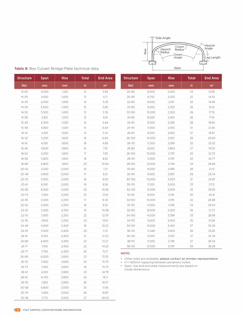
Structure Span Rise Total End Area
Ref. mm mm H m2
12-40 4,000 1,220 12 3.94
14-40 4,050 1,400 13 4.71
14-45 4,500 1,400 14 5.29
14-50 5,000 1,400 15 5.85
14-55 5,500 1,400 15 5.78
15-38 3,810 1,500 13 4.81
15-43 4,300 1,500 14 5.44
15-48 4,800 1,500 15 6.04
16-41 4,100 1,600 14 5.55
16-52 5,200 1,600 16 6.84
16-61 6,100 1,600 18 4.85
18-46 4,600 1,800 16 7.16
18-52 5,200 1,800 17 7.93
18-58 5,800 1,800 18 8.62
18-68 6,800 1,800 20 10.00
20-42 4,250 2,000 16 7.31
20-49 4,900 2,000 17 8.21
20-55 5,500 2,000 18 9.00
20-61 6,100 2,000 19 9.56
20-65 6,500 2,000 20 10.56
20-73 7,300 2,000 22 12.16
22-45 4,500 2,200 17 8.30
22-50 5,000 2,200 18 9.25
22-52 5,200 2,200 19 10.08
22-70 7,000 2,200 22 12.79
22-76 7,600 2,200 23 13.61
24-49 4,900 2,400 19 10.22
24-55 5,500 2,400 20 11.31
24-61 6,100 2,400 21 12.33
24-66 6,600 2,400 22 13.27
24-71 7,100 2,400 23 14.23
24-77 7,750 2,400 24 15.17
26-60 6,000 2,600 22 13.55
26-70 7,000 2,600 24 15.73
26-73 7,300 2,600 24 15.73
28-61 6,100 2,800 23 14.79
28-67 6,700 2,800 24 16.11
28-76 7,620 2,800 26 18.37
30-68 6,800 3,000 25 17.56
30-74 7,400 3,000 26 18.87
30-78 7,775 3,000 27 20.03
Structure Span Rise Total End Area
Ref. mm mm H m2
20-80 8,000 2,000 23 12.80
20-90 8,750 2,002 25 14.43
22-80 8,000 2,197 24 14.48
22-90 9,000 2,202 26 16.15
22-100 10,000 2,200 28 17.70
24-85 8,500 2,402 26 17.14
24-95 9,500 2,395 28 18.90
24-110 11,000 2,403 31 21.46
26-85 8,500 2,602 27 18.87
26-100 10,000 2,597 29 20.60
26-115 11,500 2,599 32 23.32
28-80 8,002 2,804 27 19.50
28-100 10,000 2,797 30 22.73
28-110 11,000 2,797 32 24.77
28-120 12,000 2,799 34 26.69
30-80 8,000 2,995 28 21.15
30-90 9,000 2,997 29 22.54
30-100 10,000 3,003 31 24.87
30-110 11,001 3,000 33 27.12
30-120 12,000 3,000 35 29.30
32-90 9,000 3,195 30 24.41
32-100 10,000 3,195 32 26.88
32-110 11,000 3,198 34 29.34
32-120 12,000 3,200 36 31.73
34-100 10,024 3,399 33 28.99
34-110 11,000 3,400 35 31.69
34-120 12,000 3,402 37 34.26
36-110 11,049 3,600 36 33.95
36-120 12,001 3,597 37 35.34
38-115 11,500 3,795 37 36.34
38-125 12,500 3,797 39 39.28
Table 8: Box Culvert Bridge-Plate technical data
NOTE:
• Other sizes are available, please contact an Armtec representative• H = 425mm (spacing between periphery holes)• Span, rise and end area measurements are based on inside dimensions
Ris
e
Span
Span
Span
Clearance Box
Span
Span
Span
Ris
e
InsideDiameter
R
Ris
e
Ris
e
Ris
e
Ris
e HaunchRadius
Side Angle
CrownRadius
CrownAngle Leg Length
HaunchAngleR
S
R T
R B
ARMTEC DRAINAGE SOLUTIONS | BRIDGE-PLATE PRODUCT GUIDE 1716 VISIT ARMTEC.COM FOR MORE INFORMATION
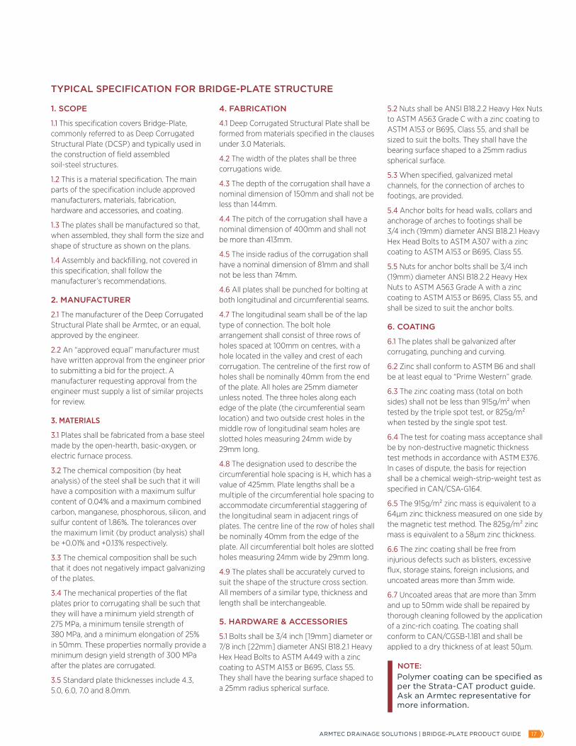
1. SCOPE
1.1 This specification covers Bridge-Plate, commonly referred to as Deep Corrugated Structural Plate (DCSP) and typically used in the construction of field assembled soil-steel structures.
1.2 This is a material specification. The main parts of the specification include approved manufacturers, materials, fabrication, hardware and accessories, and coating.
1.3 The plates shall be manufactured so that, when assembled, they shall form the size and shape of structure as shown on the plans.
1.4 Assembly and backfilling, not covered in this specification, shall follow the manufacturer’s recommendations.
2. MANUFACTURER
2.1 The manufacturer of the Deep Corrugated Structural Plate shall be Armtec, or an equal, approved by the engineer.
2.2 An “approved equal” manufacturer must have written approval from the engineer prior to submitting a bid for the project. A manufacturer requesting approval from the engineer must supply a list of similar projects for review.
3. MATERIALS
3.1 Plates shall be fabricated from a base steel made by the open-hearth, basic-oxygen, or electric furnace process.
3.2 The chemical composition (by heat analysis) of the steel shall be such that it will have a composition with a maximum sulfur content of 0.04% and a maximum combined carbon, manganese, phosphorous, silicon, and sulfur content of 1.86%. The tolerances over the maximum limit (by product analysis) shall be +0.01% and +0.13% respectively.
3.3 The chemical composition shall be such that it does not negatively impact galvanizing of the plates.
3.4 The mechanical properties of the flat plates prior to corrugating shall be such that they will have a minimum yield strength of 275 MPa, a minimum tensile strength of 380 MPa, and a minimum elongation of 25% in 50mm. These properties normally provide a minimum design yield strength of 300 MPa after the plates are corrugated.
3.5 Standard plate thicknesses include 4.3, 5.0, 6.0, 7.0 and 8.0mm.
4. FABRICATION
4.1 Deep Corrugated Structural Plate shall be formed from materials specified in the clauses under 3.0 Materials.
4.2 The width of the plates shall be three corrugations wide.
4.3 The depth of the corrugation shall have a nominal dimension of 150mm and shall not be less than 144mm.
4.4 The pitch of the corrugation shall have a nominal dimension of 400mm and shall not be more than 413mm.
4.5 The inside radius of the corrugation shall have a nominal dimension of 81mm and shall not be less than 74mm.
4.6 All plates shall be punched for bolting at both longitudinal and circumferential seams.
4.7 The longitudinal seam shall be of the lap type of connection. The bolt hole arrangement shall consist of three rows of holes spaced at 100mm on centres, with a hole located in the valley and crest of each corrugation. The centreline of the first row of holes shall be nominally 40mm from the end of the plate. All holes are 25mm diameter unless noted. The three holes along each edge of the plate (the circumferential seam location) and two outside crest holes in the middle row of longitudinal seam holes are slotted holes measuring 24mm wide by 29mm long.
4.8 The designation used to describe the circumferential hole spacing is H, which has a value of 425mm. Plate lengths shall be a multiple of the circumferential hole spacing to accommodate circumferential staggering of the longitudinal seam in adjacent rings of plates. The centre line of the row of holes shall be nominally 40mm from the edge of the plate. All circumferential bolt holes are slotted holes measuring 24mm wide by 29mm long.
4.9 The plates shall be accurately curved to suit the shape of the structure cross section. All members of a similar type, thickness and length shall be interchangeable.
5. HARDWARE & ACCESSORIES
5.1 Bolts shall be 3/4 inch [19mm] diameter or 7/8 inch [22mm] diameter ANSI B18.2.1 Heavy Hex Head Bolts to ASTM A449 with a zinc coating to ASTM A153 or B695, Class 55. They shall have the bearing surface shaped to a 25mm radius spherical surface.
5.2 Nuts shall be ANSI B18.2.2 Heavy Hex Nuts to ASTM A563 Grade C with a zinc coating to ASTM A153 or B695, Class 55, and shall be sized to suit the bolts. They shall have the bearing surface shaped to a 25mm radius spherical surface.
5.3 When specified, galvanized metal channels, for the connection of arches to footings, are provided.
5.4 Anchor bolts for head walls, collars and anchorage of arches to footings shall be 3/4 inch (19mm) diameter ANSI B18.2.1 Heavy Hex Head Bolts to ASTM A307 with a zinc coating to ASTM A153 or B695, Class 55.
5.5 Nuts for anchor bolts shall be 3/4 inch (19mm) diameter ANSI B18.2.2 Heavy Hex Nuts to ASTM A563 Grade A with a zinc coating to ASTM A153 or B695, Class 55, and shall be sized to suit the anchor bolts.
6. COATING
6.1 The plates shall be galvanized after corrugating, punching and curving.
6.2 Zinc shall conform to ASTM B6 and shall be at least equal to “Prime Western” grade.
6.3 The zinc coating mass (total on both sides) shall not be less than 915g/m² when tested by the triple spot test, or 825g/m² when tested by the single spot test.
6.4 The test for coating mass acceptance shall be by non-destructive magnetic thickness test methods in accordance with ASTM E376. In cases of dispute, the basis for rejection shall be a chemical weigh-strip-weight test as specified in CAN/CSA-G164.
6.5 The 915g/m² zinc mass is equivalent to a 64µm zinc thickness measured on one side by the magnetic test method. The 825g/m² zinc mass is equivalent to a 58µm zinc thickness.
6.6 The zinc coating shall be free from injurious defects such as blisters, excessive flux, storage stains, foreign inclusions, and uncoated areas more than 3mm wide.
6.7 Uncoated areas that are more than 3mm and up to 50mm wide shall be repaired by thorough cleaning followed by the application of a zinc-rich coating. The coating shall conform to CAN/CGSB-1.181 and shall be applied to a dry thickness of at least 50µm.
NOTE:Polymer coating can be specified as per the Strata-CAT product guide. Ask an Armtec representative for more information.
TYPICAL SPECIFICATION FOR BRIDGE-PLATE STRUCTURE
ARMTEC DRAINAGE SOLUTIONS | BRIDGE-PLATE PRODUCT GUIDE 1918 VISIT ARMTEC.COM FOR MORE INFORMATION
CONTACT INFORMATION:
Project Name and Location:
Contact and Company Name:
Email:
Telephone:
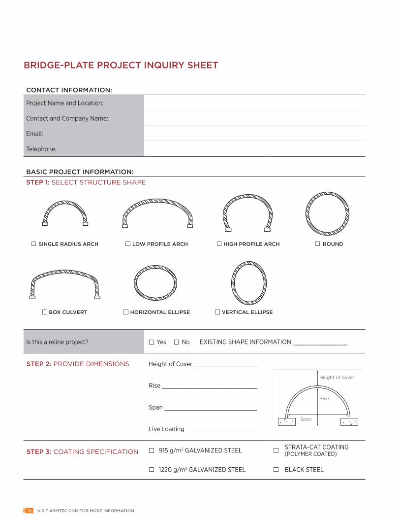
BASIC PROJECT INFORMATION:STEP 1: SELECT STRUCTURE SHAPE
Is this a reline project? Yes No EXISTING SHAPE INFORMATION __________________
STEP 2: PROVIDE DIMENSIONS Height of Cover ___________________
Rise ___________________________
Span __________________________
Live Loading ____________________
STEP 3: COATING SPECIFICATION 915 g/m2 GALVANIZED STEEL STRATA-CAT COATING (POLYMER COATED)
1220 g/m2 GALVANIZED STEEL BLACK STEEL
SINGLE RADIUS ARCH
BOX CULVERT HORIZONTAL ELLIPSE VERTICAL ELLIPSE
LOW PROFILE ARCH HIGH PROFILE ARCH ROUND
BRIDGE-PLATE PROJECT INQUIRY SHEET
Rise
Span
SINGLE RADIUS ARCH
Span
Ris
e
R
ROUNDS
InsideDiameter
LOW-PROFILE ARCH
Ris
e
Span
Ris
e
Clearance Box
Span
HIGH-PROFILE ARCH
Rise
Span
BOX CULVERT
100 TYP40
LIP
STAMP
100 TYP
OVERALL LENGTH
NET LENGTH = NUMBER OF 'H' HOLES AT 425mm
24x2
9 S
LOT
TY
P.
TH
ES
E R
OW
S
200
TY
P
120
04
0 L
IP
STA
MP
(IN
SID
E)
150
100 TYP100 TYP40 TYP
425
PLAN AND SECTION VIEW
30
of Bolt
175
88 87
180
150
c
of Boltc
Span
Rise
Height of cover
ARMTEC DRAINAGE SOLUTIONS | BRIDGE-PLATE PRODUCT GUIDE 1918 VISIT ARMTEC.COM FOR MORE INFORMATION
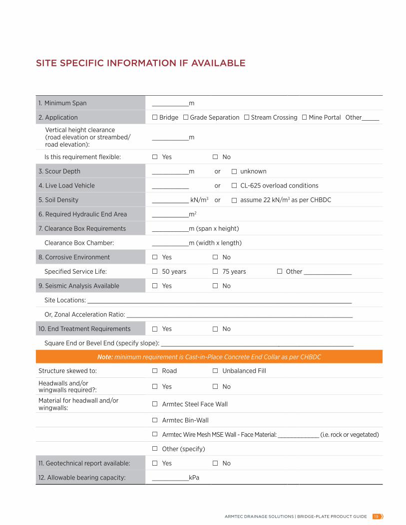
1. Minimum Span __________m
2. Application Bridge Grade Separation Stream Crossing Mine Portal Other_____
Vertical height clearance (road elevation or streambed/ road elevation):
__________m
Is this requirement flexible: Yes No
3. Scour Depth __________m or unknown
4. Live Load Vehicle __________ or CL-625 overload conditions
5. Soil Density __________ kN/m3 or assume 22 kN/m3 as per CHBDC
6. Required Hydraulic End Area __________m2
7. Clearance Box Requirements __________m (span x height)
Clearance Box Chamber: __________m (width x length)
8. Corrosive Environment Yes No
Specified Service Life: 50 years 75 years Other _____________
9. Seismic Analysis Available Yes No
Site Locations: _________________________________________________________________________
Or, Zonal Acceleration Ratio: ______________________________________________________________
10. End Treatment Requirements Yes No
Square End or Bevel End (specify slope): ______________________________________________________
Note: minimum requirement is Cast-in-Place Concrete End Collar as per CHBDC
Structure skewed to: Road Unbalanced Fill
Headwalls and/or wingwalls required?: Yes No
Material for headwall and/or wingwalls: Armtec Steel Face Wall
Armtec Bin-Wall
Armtec Wire Mesh MSE Wall - Face Material: ____________ (i.e. rock or vegetated)
Other (specify)
11. Geotechnical report available: Yes No
12. Allowable bearing capacity: __________kPa
SITE SPECIFIC INFORMATION IF AVAILABLE

–Armtec is a leading Canadian infrastructure and construction materials company combining creative engineered solutions, relevant advice, dedicated people, proven products and a national presence with a local focus on exceptional customer service.
1-877-5-ARMTEC | ARMTEC.COM
–Drawings and product details are for information and/or illustrative purposes only, and may vary. Please contact your local Armtec representative for the most current product information.–BRIDGE-PLATE / CATEGORY BROCHURE | 2016-09PROD-C01-G05_CB-2016-09-E
Find out how Bridge-Plate can be used on your next project.
Contact us today.