Breaking Invisible Specimens with Zero Force · PDF fileLoading through fabrication-induced...
20
Breaking Invisible Specimens with Zero Force Roberto Ballarini University of Minnesota Collaborators: Arthur Heuer, Hal Kahn Sponsors: NSF, DARPA, ARO, NASA Strength and Fracture Standards at the Micro and Nano Scales 1/27/08
Transcript of Breaking Invisible Specimens with Zero Force · PDF fileLoading through fabrication-induced...

Breaking Invisible Specimens with Zero Force
Roberto BallariniUniversity of Minnesota
Collaborators:
Arthur Heuer, Hal Kahn
Sponsors:
NSF, DARPA, ARO, NASA
Strength and FractureStandards at the Micro and
Nano Scales1/27/08
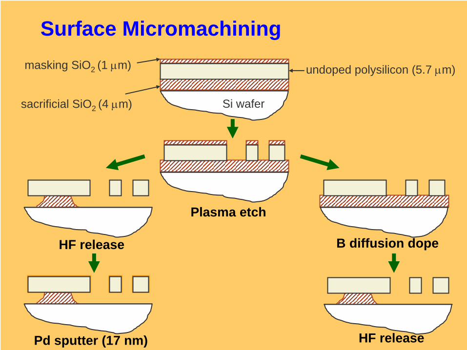
Surface Micromachining
Si wafersacrificial SiO2 (4 μm)
undoped polysilicon (5.7 μm)masking SiO2 (1 μm)
Plasma etch
Pd sputter (17 nm)
B diffusion dopeHF release
HF release
Two types of on-chip specimenshave been developed:
•Loading through electrostatic actuation•Loading through fabrication-induced residual stress
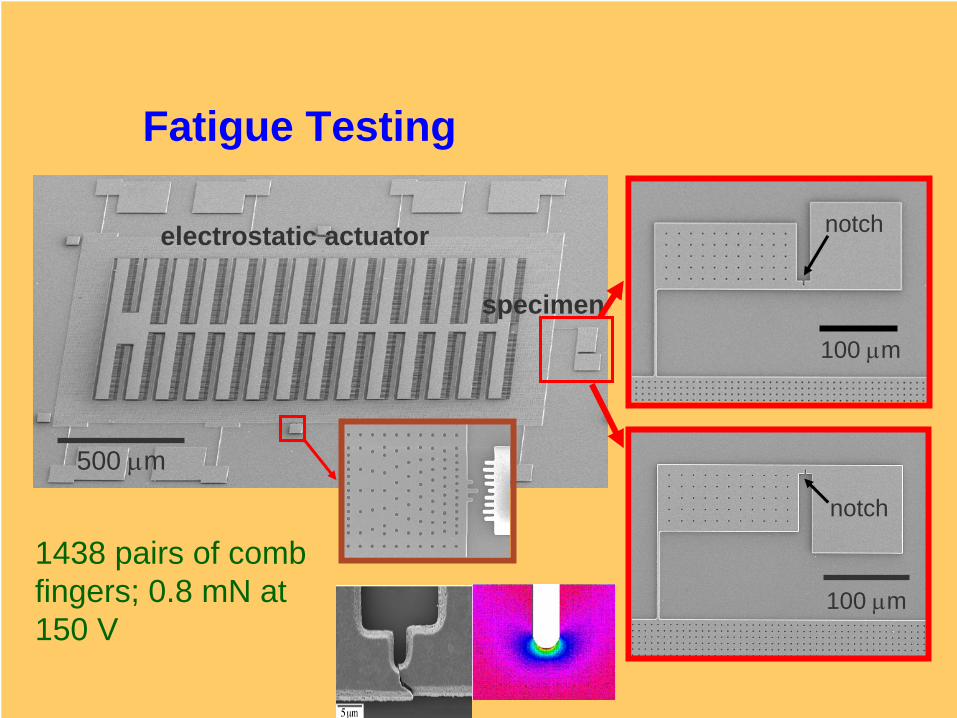
100 μm
100 μm
specimen
electrostatic actuator notch
notch
500 μm
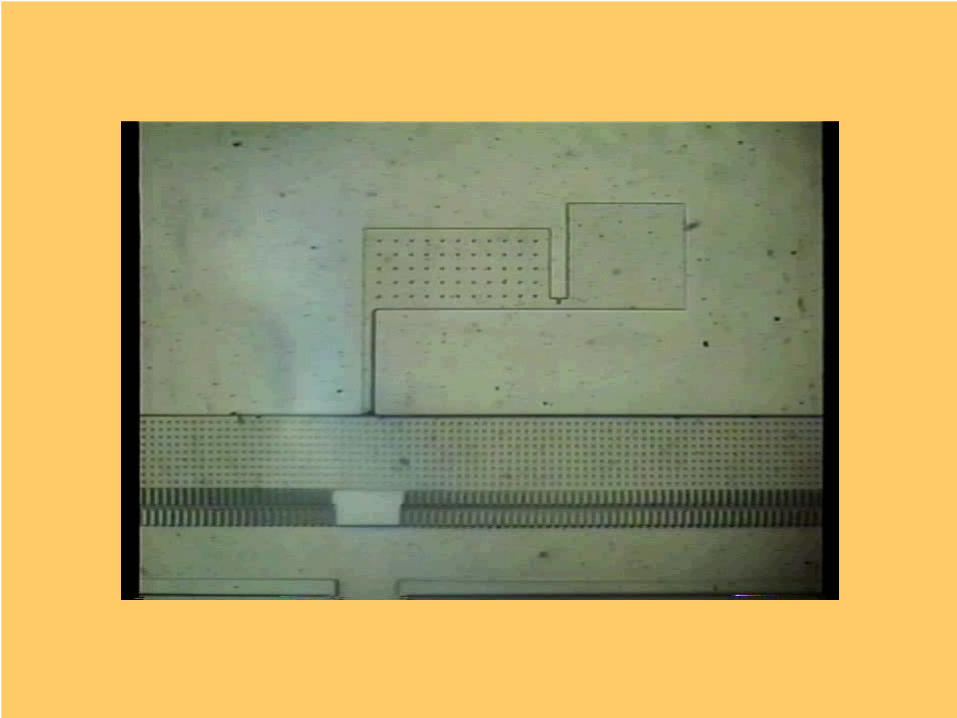
Fatigue Testing
1438 pairs of comb fingers; 0.8 mN at 150 V

ADVANTAGES OF THIS “ON-CHIP” SPECIMEN
•No need for external loading device.•Resonance loading can be used to study very high cycle fatigue.
•Uncracked ligament size of the same order as dimensions of typical MEMS components.
•Can adjust mean stress and alternating stress.
Stre
ss
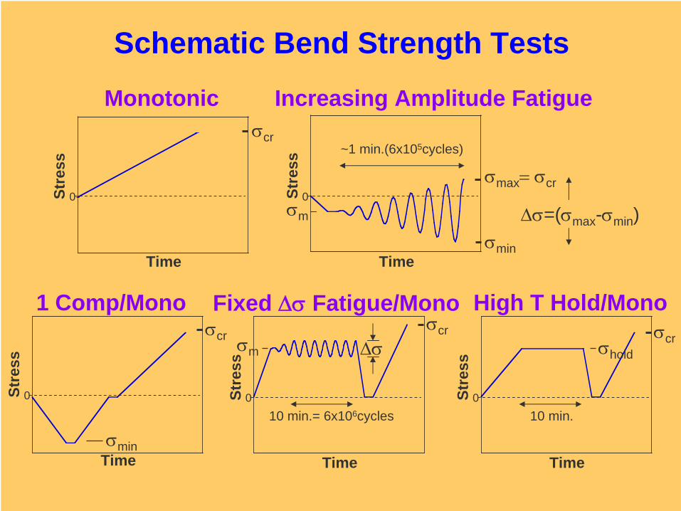
Schematic Bend Strength Tests
Monotonic Increasing Amplitude Fatigue
1 Comp/Mono Fixed Δσ
Fatigue/Mono High T Hold/Mono
Time
Stre
ss
0
σm Δσσcr
10 min.= 6x10⁶cycles
TimeSt
ress
0
σcrσhold
10 min.
Δσ=(σmax -σmin )
Time
Stre
ss
0σmax = σcr
σmin
σm
~1 min.(6x10⁵cycles)
Time
0
σcr
σmin
Time
Stre
ss
0
σcr
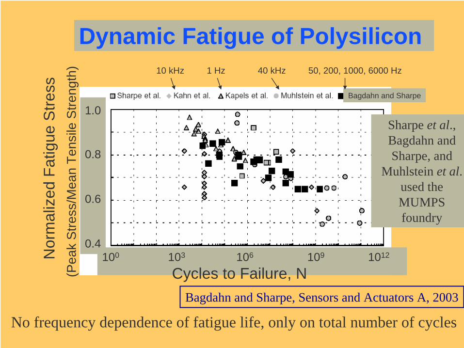
Dynamic Fatigue of Polysilicon
Bagdahn and Sharpe, Sensors and Actuators A, 2003
1.0
0.8
0.6
0.4
(Pea
k S
tress
/Mea
n Te
nsile
Stre
ngth
)
100 103 106 109 1012
Cycles to Failure, N
10 kHz 1 Hz 40 kHz 50, 200, 1000, 6000 Hz
Nor
mal
ized
Fat
igue
Stre
ss
Bagdahn and Sharpe
No frequency dependence of fatigue life, only on total number of cycles
Sharpe et al., Bagdahn and Sharpe, and
Muhlstein et al.used the MUMPSfoundry
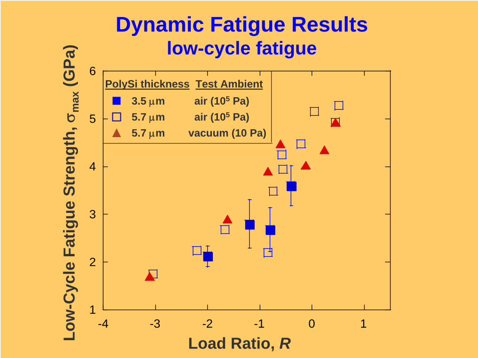
Dynamic Fatigue Resultslow-cycle fatigue
1
2
3
4
5
6
-4 -3 -2 -1 0 1
Load Ratio, RLow
-Cyc
le F
atig
ue S
tren
gth,
σm
ax(G
Pa)
PolySi thickness Test Ambient3.5 μm air (105 Pa)5.7 μm air (105 Pa)5.7 μm vacuum (10 Pa)
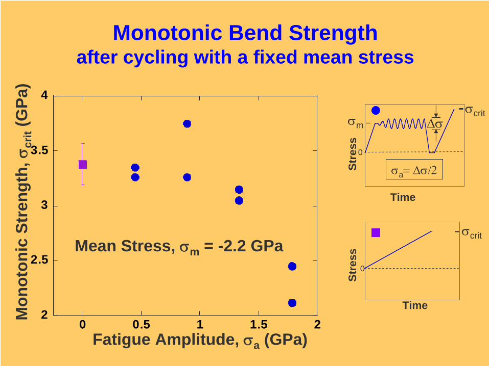
Monotonic Bend Strength after cycling with a fixed mean stress
Time
Stre
ss
0
σcrit
Time
Stre
ss
0
σm Δσσcrit
σa = Δσ/2
Mon
oton
ic S
tren
gth,
σcr
it(G
Pa)
Fatigue Amplitude, σa (GPa)
Mean Stress, σm = -2.2 GPa
2
2.5
3
3.5
4
0 0.5 1 1.5 2
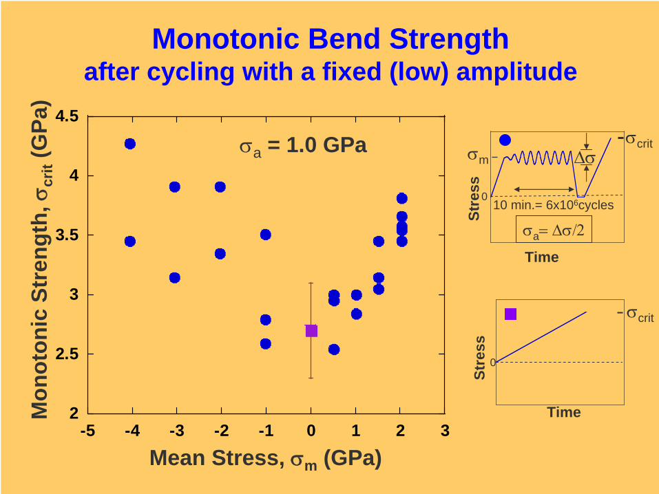
Monotonic Bend Strength after cycling with a fixed (low) amplitude
2
2.5
3
3.5
4
4.5
-5 -4 -3 -2 -1 0 1 2 3
Mean Stress, σm (GPa)
Mon
oton
ic S
tren
gth,
σcr
it(G
Pa)
σa = 1.0 GPa
Time
Stre
ss
0
σcrit
Time
Stre
ss
0
σm Δσσcrit
10 min.= 6x10⁶cycles
σa = Δσ/2
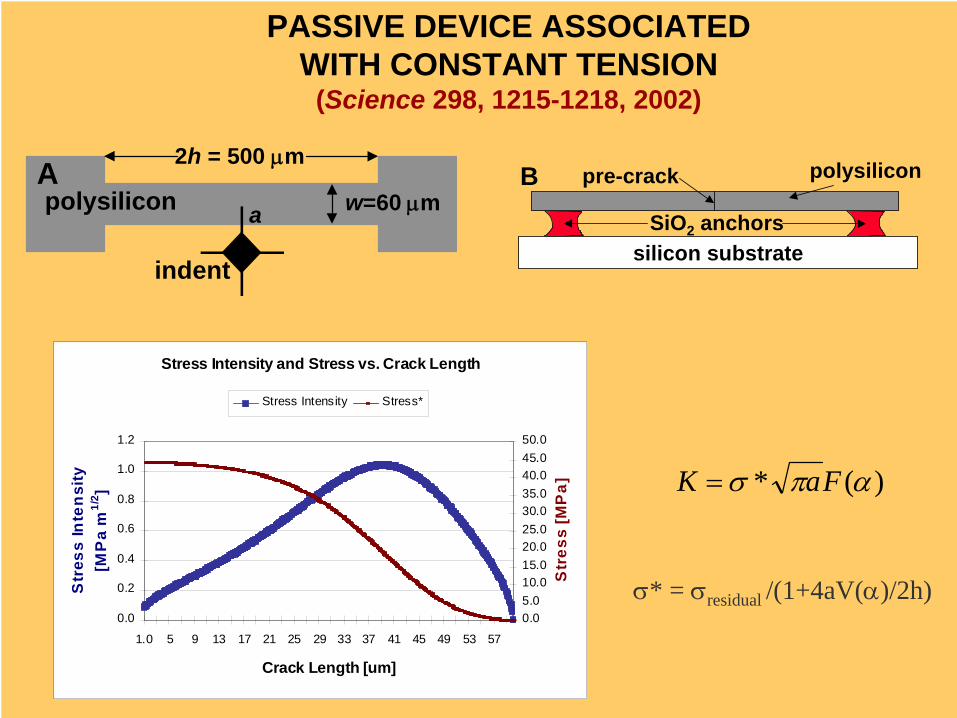
polysilicon
indent
2h = 500 μm
w=60 μmaA
silicon substrate
polysilicon
SiO2 anchors
B pre-crack
Stress Intensity and Stress vs. Crack Length
0.0
0.2
0.4
0.6
0.8
1.0
1.2
1.0 5 9 13 17 21 25 29 33 37 41 45 49 53 57
Crack Length [um]
Str
ess
Inte
nsi
ty
[MP
a m
1/2 ]
0.05.010.015.020.025.030.035.040.045.050.0
Str
ess
[MP
a]
Stress Intensity Stress*
)(* απσ FaK =
σ* = σresidual /(1+4aV(α)/2h)
PASSIVE DEVICE ASSOCIATEDWITH CONSTANT TENSION
(Science 298, 1215-1218, 2002)
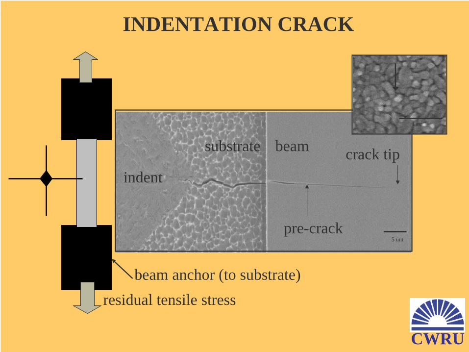
5 um
indent
substrate
pre-crack
beam
residual tensile stressbeam anchor (to substrate)
crack tip
1 um
INDENTATION CRACK
CWRU
0
0.2
0.4
0.6
0.8
1
1.2
1.4
1.6
0 5 10 15 20 25 30 35 40 45 50 55 60
Crack Length [μm]
Stre
ss In
tens
ity [M
Pa m
1/2 ]
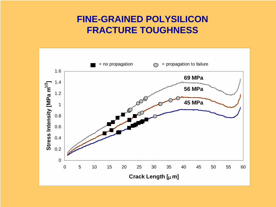
= no propagation = propagation to failure
45 MPa
56 MPa
69 MPa
FINE-GRAINED POLYSILICONFRACTURE TOUGHNESS
0
0.2
0.4
0.6
0.8
1
1.2
1.4
1.6
0 5 10 15 20 25 30 35 40 45 50 55 60
Crack Length [μm]
Stre
ss In
tens
ity [M
Pa m
1/2 ]
= no propagation = propagation to failure
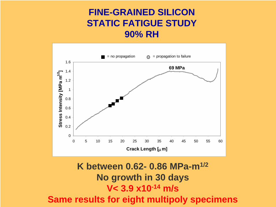
69 MPa
FINE-GRAINED SILICONSTATIC FATIGUE STUDY
90% RH
K between 0.62- 0.86 MPa-m1/2
No growth in 30 daysV< 3.9 x10⁻¹⁴ m/s
Same results for eight multipoly specimens
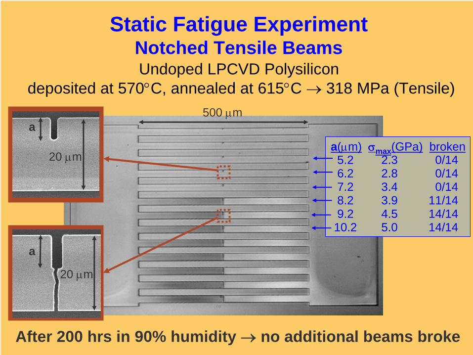
Static Fatigue ExperimentNotched Tensile BeamsUndoped LPCVD Polysilicon
deposited at 570°C, annealed at 615°C → 318 MPa (Tensile)500 μm
20 μm
a
20 μm
a
a(μm) σmax (GPa) broken5.2 2.3 0/146.2 2.8 0/147.2 3.4 0/148.2 3.9 11/149.2 4.5 14/1410.2 5.0 14/14
After 200 hrs in 90% humidity → no additional beams broke
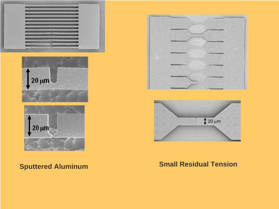
20 μm
Small Residual TensionSputtered Aluminum
Anchor
Anchor Anchor
Anchor
Anchor Anchor
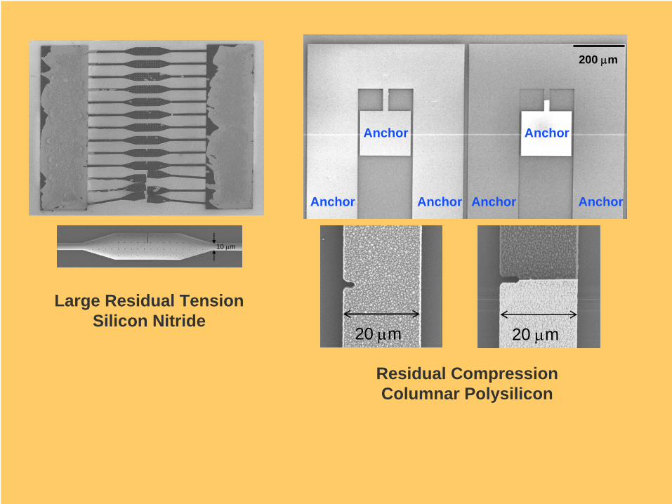
200 μm
20 μm 20 μm
10 μm
Large Residual TensionSilicon Nitride
Residual CompressionColumnar Polysilicon
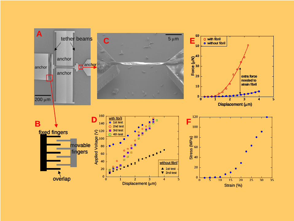
0
20
40
60
80
100
120
140
160
0 1 2 3 4 5
1st test2nd test3rd test4th test
with fibril
1st test2nd test
without fibril
Displacement (μm)
Appl
ied
Vol
tage
(V)
0
20
40
60
80
100
120
0 5 10 15 20 25 30 35
Strain (%)S
tress
(MP
a)
200 μm
5 μmA
B D
C
0
10
20
30
40
50
60
0 1 2 3 4 5
Displacement (μm)
Forc
e (μ
N)
extra force needed to strain fibril
with fibrilwithout fibril
0
10
20
30
40
50
60
0 1 2 3 4 5
Displacement (μm)
Forc
e (μ
N)
extra force needed to strain fibril
0
10
20
30
40
50
60
0 1 2 3 4 5
Displacement (μm)
Forc
e (μ
N)
extra force needed to strain fibril
with fibrilwithout fibril
F
E
fixed fingers
overlap
movablefingers
tether beams
anchor
anchoranchor anchor
0
20
40
60
80
100
120
140
160
0 1 2 3 4 5
1st test2nd test3rd test4th test
with fibril
1st test2nd test
without fibril
Displacement (μm)
Appl
ied
Vol
tage
(V)
0
20
40
60
80
100
120
0 5 10 15 20 25 30 35
Strain (%)S
tress
(MP
a)
200 μm
5 μmA
B D
C
0
10
20
30
40
50
60
0 1 2 3 4 5
Displacement (μm)
Forc
e (μ
N)
extra force needed to strain fibril
with fibrilwithout fibril
0
10
20
30
40
50
60
0 1 2 3 4 5
Displacement (μm)
Forc
e (μ
N)
extra force needed to strain fibril
0
10
20
30
40
50
60
0 1 2 3 4 5
Displacement (μm)
Forc
e (μ
N)
extra force needed to strain fibril
with fibrilwithout fibril
F
E
fixed fingers
overlap
movablefingers
fixed fingers
overlap
movablefingers
tether beams
anchor
anchoranchor anchor


![NaOCl [μM] - MDPI](https://static.fdocument.org/doc/165x107/62607d508c664043d559d161/naocl-m-mdpi.jpg)