
Benalmadena, Spain, 29 Oct - 4 Nov, 1992. Φ-Factory Design · "Frontiers of Particle Beams,...
21
Lecture given at the joint US-CERN School on Particle Accelerators "Frontiers of Particle Beams, Factories with e + e - Rings", Benalmadena, Spain, 29 Oct - 4 Nov, 1992. Φ-Factory Design C. Biscari INFN - Laboratori Nazionali di Frascati. C.P. 13 - 00044 Frascati (RM) - Italia Introduction The search for fundamental interaction laws stimulates continuously the accelerator community to push up the energy of accelerators. Recently the interest for high accuracy measurements in already explored energy regions put forward the requirement for a new generation of colliders, the e + e - factories, working at the energies of hadronic resonances and producing a very high rate of events with a luminosity increased by at least two orders of magnitude with respect to the present values. Such high luminosity poses interesting new problems to both the detector and accelerator physicists. The lowest energy factory is expected to work at the Φ resonance (~ 1 GeV) and is mainly dedicated to the investigation of CP violation. The construction of a collider in Φ energy range requires a relatively small investment, in terms of budget and man power, and can therefore be afforded by medium size laboratories. A strong advantage for this kind of project is the small size of the groups which allows the participation to all problems concerning the detector and the accelerator. The basic requirements of a Φ-Factory are: - Luminosity = 10 32 ÷ 10 33 cm -2 sec -1 at the c.m. energy of 1.02 GeV. This is a challenging request: the maximum luminosity in this energy range has been obtained by VEPP-2M 1 and is two orders of magnitude lower (L ~ 5 10 30 cm -2 sec -1 ). The maximum luminosity ever obtained is of the same order but has been obtained at an energy one order of magnitude larger (L ~ 1.8 10 32 cm -2 sec -1 at the energy of 5.3 GeV in CESR 2 ). - High average luminosity. The peak cross-section at the Φ resonance is: σ peak = 4.4 10 -30 cm 2
Transcript of Benalmadena, Spain, 29 Oct - 4 Nov, 1992. Φ-Factory Design · "Frontiers of Particle Beams,...
Lecture given at the joint US-CERN School on Particle Accelerators"Frontiers of Particle Beams, Factories with e+e- Rings",
Benalmadena, Spain, 29 Oct - 4 Nov, 1992.
Φ-Factory Design
C. Biscari
INFN - Laboratori Nazionali di Frascati. C.P. 13 - 00044 Frascati (RM) - Italia
Introduction
The search for fundamental interaction laws stimulates continuously the
accelerator community to push up the energy of accelerators. Recently the
interest for high accuracy measurements in already explored energy
regions put forward the requirement for a new generation of colliders, the
e+ e- factories, working at the energies of hadronic resonances and
producing a very high rate of events with a luminosity increased by at least
two orders of magnitude with respect to the present values. Such high
luminosity poses interesting new problems to both the detector and
accelerator physicists.
The lowest energy factory is expected to work at the Φ resonance
(~ 1 GeV) and is mainly dedicated to the investigation of CP violation. The
construction of a collider in Φ energy range requires a relatively small
investment, in terms of budget and man power, and can therefore be
afforded by medium size laboratories. A strong advantage for this kind of
project is the small size of the groups which allows the participation to all
problems concerning the detector and the accelerator.
The basic requirements of a Φ-Factory are:
- Luminosity = 1032 ÷ 1033 cm-2 sec-1 at the c.m. energy of 1.02 GeV. This
is a challenging request: the maximum luminosity in this energy range
has been obtained by VEPP-2M1 and is two orders of magnitude lower
(L ~ 5 1030 cm-2 sec-1). The maximum luminosity ever obtained is of the
same order but has been obtained at an energy one order of magnitude
larger (L ~ 1.8 1032 cm-2sec-1 at the energy of 5.3 GeV in CESR2).
- High average luminosity. The peak cross-section at the Φ resonance is:
σpeak = 4.4 10-30 cm2
2
The Φ production required for the precision experiments on CP viola-tion is at least 1010 events per year, which corresponds to L = 2.3 1032
cm-2 sec-1 with 107 seconds in a year; to obtain such a high average lu-minosity a very reliable storage ring is needed.
- Large free solid angle in the detector: the dream of the experimentalistsis a storage ring with a high luminosity and no machine componentsnear the luminosity source, which of course are conflicting require-ments. Coordinated designs of detector and accelerator are necessary.
Most of experimental proposals ask for symmetric energies: twobeams colliding at 510 MeV, with equal parameters (beam current, emit-tance, dimensions, energy spread). The possibility of using Linac againstring will not be treated in this lesson. A general overview will be given onthe Φ-Factory design strategy, on the main new items and on the existingprojects.
1 Basic design parameters
The single bunch luminosity for an electron-positron storage ring collideris given by the well known formula:
L = f N2
4π σx σy (1)
where f is the collision frequency, N is the number of electrons andpositrons per bunch (assumed to be the same) and σx and σy are the hori-zontal and vertical rms beam sizes at the interaction point (IP).
The luminosity is limited by the beam-beam interaction. When twobeams collide, one sees the other as a focusing lens, whose strength isgiven by a dimensionless parameter, the so called beam-beam tune shift
ξx = re N βx
2π γ σx (σx+σy) ξy = re N βy
2π γ σy (σx+σy) (2)
re being the classical electron radius, βx,y the betatron functions at the IP,and γ the particle energy in units of its rest mass. The value of ξ has anempirical limit that will be discussed later. In order to maximize theluminosity L it is convenient to have the beam-beam tune shifts maximum
3
and equal in the two planes; this is possible if the ratio between theemittances, the coupling factor κ, is equal to the ratio of the beam rmssizes at the IP. It follows that κ is also equal to the ratio of the betatronfunctions at the IP:
κ = εx
εy =
σxσy
= βxβy (3)
With ε = εx + εy , the beam-beam tune shift can be rewritten as:
ξ = re
2πγ Nε (4)
By introducing ξ in the luminosity expression, we set:
L = π f γ 2
re2 ξ2 ε (1 + κ)
βy = π f γ 2
re2 ξ2 ε (1 + κ)
κ βx (5)
This formula shows the relevant accelerator parameters to play with
in order to maximize the luminosity; a discussion on each of them follows
to illustrate the choices that can be made.
1.1 Linear tune shift parameter ξ
When two beams collide the electromagnetic interaction between particles
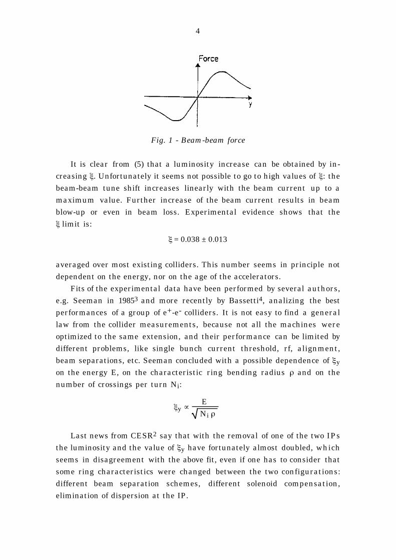
acts as a focusing lens producing a tune shift. The interaction force is lin-
ear only up to an extent of about one rms beam size and has its maximum
at 1.6 σ (see Fig. 1). The beam-beam tune shift linear part, given by (2), is
proportional to the beam density (strength of the interaction), to the beta-
tron function β (sensitivity to interaction) and inversely to γ (rigidity of the
beam). The focusing strength on a particle and therefore its tune shift
depend on the particle position inside the bunch: due to beam-beam
interaction a tune spread arises whose width is well represented by ξ,
because the maximum tune shift corresponds to particles which are
inside the core of the bunch distribution and therefore see the linear part of
the interaction force.
4
Fig. 1 - Beam-beam force
It is clear from (5) that a luminosity increase can be obtained by in-creasing ξ. Unfortunately it seems not possible to go to high values of ξ: thebeam-beam tune shift increases linearly with the beam current up to amaximum value. Further increase of the beam current results in beamblow-up or even in beam loss. Experimental evidence shows that theξ limit is:
ξ = 0.038 ± 0.013
averaged over most existing colliders. This number seems in principle notdependent on the energy, nor on the age of the accelerators.
Fits of the experimental data have been performed by several authors,e.g. Seeman in 19853 and more recently by Bassetti4, analizing the bestperformances of a group of e+-e- colliders. It is not easy to find a generallaw from the collider measurements, because not all the machines wereoptimized to the same extension, and their performance can be limited bydifferent problems, like single bunch current threshold, rf, alignment,beam separations, etc. Seeman concluded with a possible dependence of ξy
on the energy E, on the characteristic ring bending radius ρ and on thenumber of crossings per turn Ni:
ξy ∝ E
Ni ρ
Last news from CESR2 say that with the removal of one of the two IPsthe luminosity and the value of ξy have fortunately almost doubled, whichseems in disagreement with the above fit, even if one has to consider thatsome ring characteristics were changed between the two configurations:different beam separation schemes, different solenoid compensation,elimination of dispersion at the IP.
5
Bassetti has considered a larger number of colliders including old andlow energy accelerators, and new and high energy ones like LEP, andfound that the best fit for ξy is the following:
ξy ∝ 1
(ρ Ni ).4 (E
βx
εx ) .5 κ−1.7
It is interesting to note that the fit does not depend on the energy E,because even if E appears in the formula, being εx proportional to E2, the Edependence cancels out. The fit favours flat beams against round.
Anyway, when designing a new factory, a more or less conservativevalue for ξ must be assumed, so fixing N/ε.
ξ may change with the tune in a not easily predictable way: the ringlattice should therefore be widely flexible, in order to compensate for un-expected effects in the beam-beam interaction.
1.2 Low beta
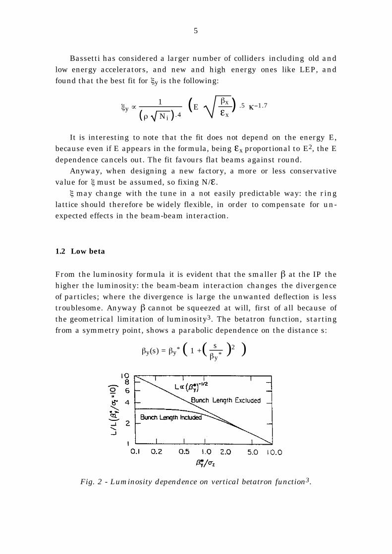
From the luminosity formula it is evident that the smaller β at the IP thehigher the luminosity: the beam-beam interaction changes the divergenceof particles; where the divergence is large the unwanted deflection is lesstroublesome. Anyway β cannot be squeezed at will, first of all because ofthe geometrical limitation of luminosity3. The betatron function, startingfrom a symmetry point, shows a parabolic dependence on the distance s:
βy(s) = βy* ( 1 +( sβy* )2 )
Fig. 2 - Luminosity dependence on vertical betatron function3.
6
The betatron function within the bunch increases rapidly, so that tokeep the advantage of having a low beta, βy* must be larger than the halfbunch length σz which is determined by the ring rf system, impedancesand single bunch instability thresholds.
Moreover low βy* implies high chromaticity with a corresponding re-duction of dynamic aperture and also strong focusing near the IP, wherenormally there is lack of free space because of detector requirements.
Reasonable values for both σz and βoy are in the order of few centime-ters.
1.3 Emittance
The equilibrium emittance is determined by the radiation process whichdepends mostly on the characteristic radius of the bending field, and onthe properties of the lattice.
To increase the luminosity one would like to have large emittance, butε cannot be made arbitrarily large because of the machine physical aper-ture necessary for a reasonable beam lifetime.
The dynamic aperture is also sensitive to ε: large emittance meansthat most particles perform betatron oscillations in the magnetic field re-gion where multipole components are more dangerous.
Furthermore, being ξ ∝ N/ε, increasing ε means increasing thebunch current, to which beam instabilities are related.
The relatively large value of the emittance (~ 1 mm mrad) can be ob-tained either with small bending radius dipoles or with wigglers which al-low also emittance tuning.
1.4 Coupling factor κ
The coupling factor can be chosen between 0 and 1, corresponding respec-tively to a very flat or to a round beam.
κ = 1 implies round beam at the IP: βx = βy , εx = εy, σx = σy
For the Φ-Factory, due to the relatively low energy of the beam, it ispossible, at least in principle, to focus a round beam to the low beta valueswith a solenoidal field, while in higher energy rings quadrupoles are nec-essary to obtain strong focusing and it is critical to focus in both planes atthe same point in the lattice.
7
With κ = 1 a factor 2 is directly gained on the luminosity (see formula5). Some beam-beam simulations claim that a higher ξ can be obtained5,6
but this has not yet been tested. There exists a very interesting proposal ofmaking round beams in VEPP-2M7, to check the physics of beam-beam in-teraction in this configuration.
Strong focusing in both planes tends to increase the maximum valueof the betatron functions near the IP. As a consequence, the chromaticitygrows up and the aperture requirements become more demanding in thehorizontal plane. Also the vertical aperture becomes critical due to the ver-tical emittance, with the obvious drawback on vacuum and complexity ofelement designs.
A low value of κ implies a flat beam, with a vertical emittance muchsmaller than the horizontal. Such a choice is convenient from the point ofview of apertures and chromaticity, because only one of the planes is criti-cal.
It implies also reduction of ion trapping, which is very important inmultibunch operation.
Accurate orbit correction to ensure the design coupling is necessary.
1.5 Collision frequency
There are two basic strategies to increase the collision frequency: to storethe beams in two rings in multibunch operation and intersect at one ormaximum two IPs, or alternatively to use very compact rings and only onebunch per beam.
The compact ring design maximum collision frequency is few tens ofMHz and therefore the single bunch luminosity:
Lo = L / nb
where nb is the number of bunches in each beam, must be pushed well be-yond the limit of existing machines, while in double ring multibunch op-eration the value of Lo is of the order of that achieved in operating ma-chines and it is the number of bunches that must be increased.
Both choices have their advantages and drawbacks, which will be dis-cussed later.
8
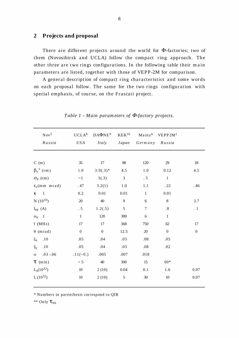
2 Projects and proposal
There are different projects around the world for Φ-factories; two ofthem (Novosibirsk and UCLA) follow the compact ring approach. Theother three are two rings configurations. In the following table their mainparameters are listed, together with those of VEPP-2M for comparison.
A general description of compact ring characteristics and some wordson each proposal follow. The same for the two rings configuration withspecial emphasis, of course, on the Frascati project.
Table 1 - Main parameters of Φ-factory projects.
Nov5 UCLA8 DAΦNE9 KEK10 Mainz6 VEPP2M1
Russia USA Italy Japan Germany Russia
C (m) 35 17 98 120 29 18
βy* (cm) 1.0 3.9(.3)* 4.5 1.0 0.12 4.5
σz (cm) ~1 3(.3) 3 . 5 1
εx(mm mrad) . 47 3.2(1) 1.0 1.1 . 22 . 46
κ 1 0.2 0.01 0.01 1 0.01
N (1010) 20 40 9 6 8 3.7
Itot (A) . 5 1.2(.5) 5 7 .8 . 1
nb 1 1 120 300 6 1
f (MHz) 17 17 368 750 62 17
θ (mrad) 0 0 12.5 20 0 0
ξx .10 .05 .04 .03 .08 .05
ξy .10 .05 .04 .03 .08 .02
α .03 -.06 .11(~0.) .005 .007 .018
τ (min) < 5 40 300 15 60*
Lo(1032) 10 2 (10) 0.04 0.1 1.6 0.07
L (1032) 10 2 (10) 5 30 10 0.07
* Numbers in parenthesis correspond to QIR
** Only τbb
9
3 Compact ring
The size of a Φ detector is of the order of 3 to 5 m; to fit it inside a ring aminimum circumference of ~ 20 m is needed, corresponding to a maxi-mum collision frequency of the order of 15 MHz. This relatively low valueof f implies that to obtain the desired luminosity οne or more of the follow-ing parameters must be pushed to critical values: low beta; emittance;bunch density; beam-beam tune shift.
The small bending radius can be obtained with superconductingdipoles, whose high nonlinearities can limit the dynamic aperture, al-ready critical due to the large emittance.
The large synchrotron radiation power density on the vacuum cham-ber walls must be faced with special design of the vacuum chamber (forexample the antichamber at the UCLA ring).
A fundamental problem of the compact ring is the high rate of particleloss due to single beam-beam bremsstrahlung which shortens the lifetimeto few minutes. Continuous filling of the ring is necessary.
3.1 Novosibirsk Φ - Factory
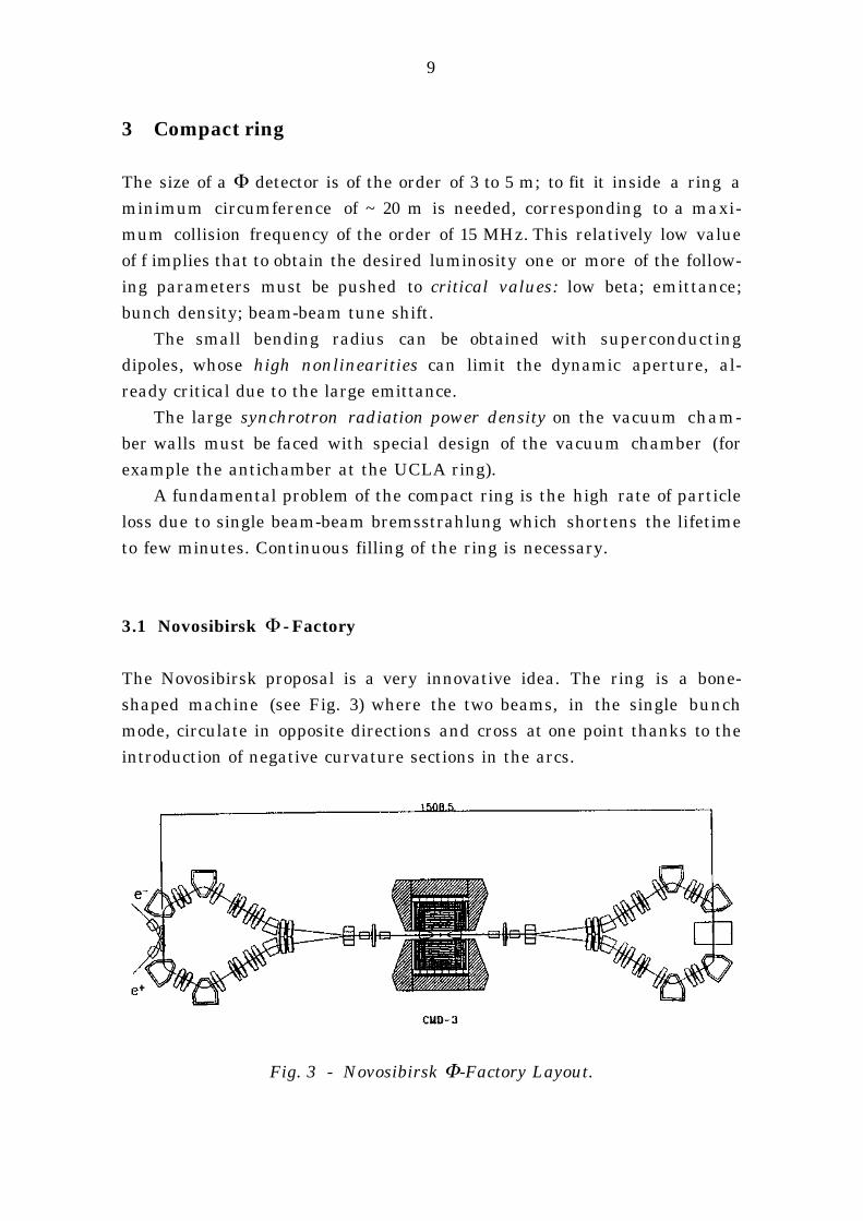
The Novosibirsk proposal is a very innovative idea. The ring is a bone-shaped machine (see Fig. 3) where the two beams, in the single bunchmode, circulate in opposite directions and cross at one point thanks to theintroduction of negative curvature sections in the arcs.
Fig. 3 - Novosibirsk Φ-Factory Layout.
10
Round beams are used: a sc solenoid (11 T) around the IP rotates the
transverse planes by π/2: the betatron oscillation normal modes are verti-
cal in one arc and horizontal in the other so that the emittances in the two
planes are the same. Beams are focused to very small beta values in both
planes by the same solenoid.
A very high value of ξ (> 0.1) is claimed to be obtainable.
The working point is placed on the main coupling resonance νx
- νy = 0. The tunes are shifted along the coupling resonance and do not
trespass on the 2-dimensional coupling sidebands.
SC dipoles (6.5 T) are used to obtain the small bending radius.
The beam lifetime of few minutes is considered satisfactory and man-
ageable with the injection chain, consisting of a full energy linac and a
positron cooling ring.
A later stage with 3 bunches per beam is envisaged, applying electro-
static beam separation at the IP sides to reach luminosities higher than
1033 cm-2 sec-1.
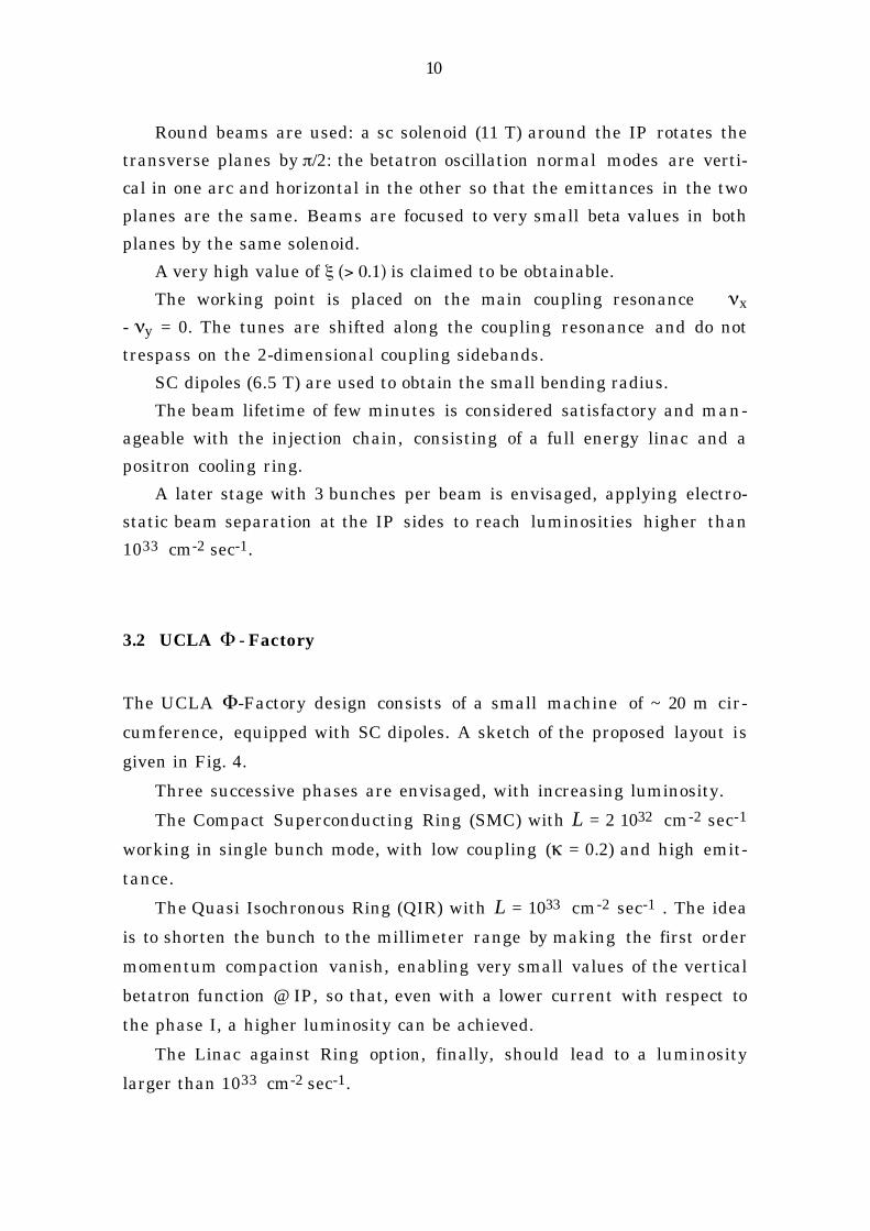
3.2 UCLA Φ - Factory
The UCLA Φ-Factory design consists of a small machine of ~ 20 m cir-
cumference, equipped with SC dipoles. A sketch of the proposed layout is
given in Fig. 4.
Three successive phases are envisaged, with increasing luminosity.
The Compact Superconducting Ring (SMC) with L = 2 1032 cm-2 sec-1
working in single bunch mode, with low coupling (κ = 0.2) and high emit-
tance.
The Quasi Isochronous Ring (QIR) with L = 1033 cm-2 sec-1 . The idea
is to shorten the bunch to the millimeter range by making the first order
momentum compaction vanish, enabling very small values of the vertical
betatron function @ IP, so that, even with a lower current with respect to
the phase I, a higher luminosity can be achieved.
The Linac against Ring option, finally, should lead to a luminosity
larger than 1033 cm-2 sec-1.
11
Fig. 4 - UCLA Φ-Factory layout.
4 Double ring-multibunch operation
The choice of increasing the collision frequency by storing many bunches
in two rings leads to a design based on conventional technology, as far as
the lattice is concerned.
The short distance between bunches obliges the beams to cross at an
angle in order to suppress parasitic crossings.
The key problem are multibunch instabilities which must be faced
with feedback systems specially designed, rf cavity design with HOM sup-
pression and low impedance in all vacuum chamber components.
The discussion of the main characteristics of this kind of project will
follow the DAΦNE criteria design. The KEK project will be shortly de-
scribed later, as it follows more or less the same criteria.
12
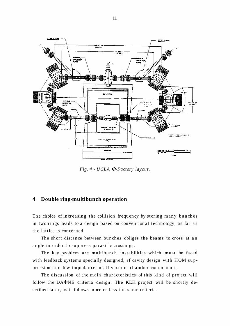
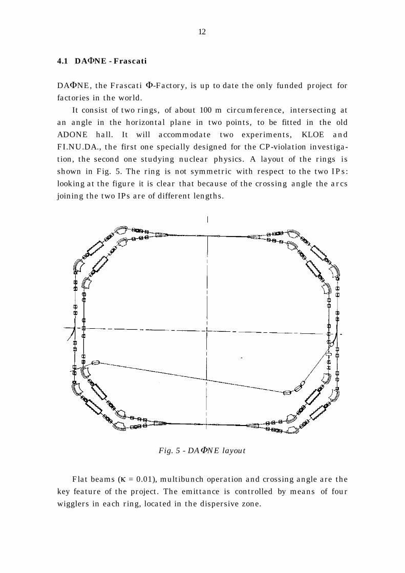
4.1 DAΦNE - Frascati
DAΦNE, the Frascati Φ-Factory, is up to date the only funded project forfactories in the world.
It consist of two rings, of about 100 m circumference, intersecting atan angle in the horizontal plane in two points, to be fitted in the oldADONE hall. It will accommodate two experiments, KLOE andFI.NU.DA., the first one specially designed for the CP-violation investiga-tion, the second one studying nuclear physics. A layout of the rings isshown in Fig. 5. The ring is not symmetric with respect to the two IPs:looking at the figure it is clear that because of the crossing angle the arcsjoining the two IPs are of different lengths.
Fig. 5 - DAΦNE layout
Flat beams (κ = 0.01), multibunch operation and crossing angle are thekey feature of the project. The emittance is controlled by means of fourwigglers in each ring, located in the dispersive zone.
13
Being the two experiment detectors equipped with strong solenoids
(0.6 T x 2.1 m @KLOE and 1.5 T x 2 m @ FI.NU.DA), the perturbation of the
machine optics obliges a coordinated design of the interaction region and
the detector.
The interaction regions in between the two splitting magnets which
separate the two beam trajectories, are shared by the two rings. The mag-
netic axis of their elements is the bisectrice of the nominal closed orbits of
the two rings. The two interaction regions are equivalent from the optics
point of view, i.e. with the same first order transfer matrix, so that the op-
tical functions and the beam separation are the same at the Interaction
Region ends. This solution simplifies injection, tuning and chromaticity
correction in the different modes of operation.
In the Interaction Regions the transverse coupling due to the detector
solenoid is corrected by two compensating solenoids at the detector ends
whose total field integral is opposite to the detector one. In both experi-
ments all or some of the low beta quadrupoles are immersed in the
solenoidal field. To eliminate the coupling effect quadrupoles should be ro-
tated following the angle given by:
θsol = ⌡⌠
Bz dz 2Bρ
This continuos rotation is not feasible with a real quadrupole, so each
quadrupole will be rotated by the average value of θsol along its length. To
eliminate the residual coupling four parameters are needed, and the rota-
tion angle of the three quadrupoles plus the field of the compensator
solenoid can be used to block-diagonalize the transfer matrix from the IP
to the split magnet.
4.1.1 Crossing angle
In multibunch configuration the reduced bunch to bunch distance forbids
head-on collisions and beams must cross with an angle. Crossing can be
in the horizontal or in the vertical plane. When beams collide with an an-
gle synchro-betatron coupling arises: this has been proved in Doris11 and
by beam-beam simulations12. This effect can be avoided with a crab
14
crossing scheme. The original idea was given by R. Palmer13 for linear
colliders and it has been later applied to ring colliders14. The principle is
the following: a transverse deflecting rf cavity, located π/2 in β-phase ad-
vance from the IP and with the zero-crossing of the electrical field syn-
chronous with the bunch center, gives to a particle an angular kick pro-
portional to its distance from the bunch center. This kick transforms into a
transverse displacement at the IP, thereby making the two bunches tilt
and collide head-on. Another cavity, π away from the first, restores the
original bunch orientation. This geometry allows a bunch spacing closer
than a normal head-on collision, and consequently a higher collision fre-
quency.
The required cavity voltage, assuming that the rms bunch length σz is
small compared to λrf/4, where λrf is the rf wavelength of the cavity, is:
Vrf = E
4πe θλrf
β* βc
being θ half the crossing angle, β* the betatron function at the IP, βc at the
cavity location, both in the crossing plane.
This scheme requires rf phase ϕ and amplitude stability:
∆ϕ << 4πσθλrf
∆VrfVrf
<< 1
Nβ σσz
being σ the rms bunch size at the IP in the crossing plane and Nβ the
number of turns in a betatron damping time. With a flat beam, since βx is
much larger than βy, the cavity amplitude Vrf is much lower and the tol-
erances much larger for the crossing in the horizontal plane. In fact tol-
erances are so large that for DAΦNE characteristic parameters a cavity is
not necessary.
The key parameter describing the effect of the crossing angle on beam
dynamics is what is called the badness factor a:
a = θ σLσx
15
It is a measure of the coupling between the radial and the longitudinal
phase spaces generated by the crossing angle. This coupling, experimen-
tally observed in DORIS I11, limits the maximum achievable tune shift
and, consequently the luminosity.
The simplest hypothesis one can make on the relation between a and ξ
is:
ξa = const
Suggestions on this value come both from observations at DORIS I and
computer simulations. At DORIS I the maximum value of the tune shift
ever obtained and the value of a were:
ξ = 0.01 , a = 0.5
In DAΦNE a ~ 14 θ, so that an angle of ~ 10 mrad seems safe from this
point of view. Simulations15 of particle tracking including beam-beam in-
teraction with crossing angle confirm that no synchro-betatron dangerous
coupling occurs up to an angle of ~ 100 mrad.
The effect of parasitic crossings must also be considered: when two
beams collide at an angle 2θ the first parasitic crossing (p.c.) occurs at dis-
tance l/2 (l is the spacing between bunches) from the IP, being the bunches
centers at a distance given by d = l θ.The tune shift due to the parasitic crossing is:
ξx = ro Nβx
2π γ d2 ξy = ro Nβy
2π γ d2
where βx, βy are the betatron functions at the p.c. From the consideration
that one beam could act as a scraper for the opposite beam particles pass-
ing inside its core, a criteria had arised16: the full separation should be at
least 7σ so that particles one wishes to keep in the beam stay out of the
opposite beam center.
To check this criteria simulations have been done with DAΦNE pa-
rameters17, using the approximation of weak-strong interactions.
16
Two different effects have shown:- Blow-up in the vertical emittance for particles inside the core which af-
fect the luminosity (σy increase).- Long vertical tails for particles which passes near the core of the oppo-
site bunch which can affect the beam lifetime.Both the effects depend on the current, on the beam separation, and on
the betatron functions at crossing, but we got no evidence of the scrapereffect. In fact a particle passing inside the opposite beam gets a tune shiftwhich affects its betatron motion, but not necessarily cuts it out, alsobecause a particle which sees the other bunch at one turn will probably notpass inside it again in the successive turns during a betatron dampingtime.
With DAΦNE design parameters 7σ at the p.c. is a safe number, butfor example with a higher current a separation of 7σ would affect beamlifetime.
4.1.2 Rf and feedback system
The rf system must face one of the most harmful problems in high currentstorage rings working in multibunch operation: the high order modes(HOMs) of the rf cavities induce coupling of the relative motion of the nb
bunches through the wake fields left behind in the cavity by the bunchesthemselves giving rise to multibunch instabilities. The instability growthrate must be kept below the radiation damping rate by a proper cavity de-sign and an appropriate feedback system.
The rf voltage necessary to compensate the energy losses due to syn-chrotron radiation and to HOMs is not very high (<< 1 MV): room temper-ature cavities are used. The choice of the frequency is usually related to theavailability of rf sources together with the bunch length requirements: 350,500 MHz are the most commonly used.
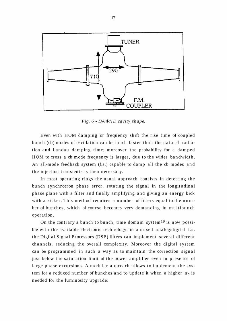
A large amount of R & D (Frascati, SLAC)18 is in progress to develop arf cavity having the lowest possible interaction with the beam spectrum.The research is essentially dedicated to two items:* Cavity shape optimization to reduce the number of "trapped" HOMs by
means of long tapered tubes (R/Q is reduced by an order of magnitude).Fig. 6 shows a sketch of the cavity shape model proposed for DAΦNE.
* HOM damping by coupling the more dangerous parasitic modes withloops or with waveguides propagating at their frequencies.
17
Fig. 6 - DAΦNE cavity shape.
Even with HOM damping or frequency shift the rise time of coupled
bunch (cb) modes of oscillation can be much faster than the natural radia-
tion and Landau damping time; moreover the probability for a damped
HOM to cross a cb mode frequency is larger, due to the wider bandwidth.
An all-mode feedback system (f.s.) capable to damp all the cb modes and
the injection transients is then necessary.
In most operating rings the usual approach consists in detecting the
bunch synchrotron phase error, rotating the signal in the longitudinal
phase plane with a filter and finally amplifying and giving an energy kick
with a kicker. This method requires a number of filters equal to the num-
ber of bunches, which of course becomes very demanding in multibunch
operation.
On the contrary a bunch to bunch, time domain system19 is now possi-
ble with the available electronic technology: in a mixed analog/digital f.s.
the Digital Signal Processors (DSP) filters can implement several different
channels, reducing the overall complexity. Moreover the digital system
can be programmed in such a way as to maintain the correction signal
just below the saturation limit of the power amplifier even in presence of
large phase excursions. A modular approach allows to implement the sys-
tem for a reduced number of bunches and to update it when a higher nb is
needed for the luminosity upgrade.
18
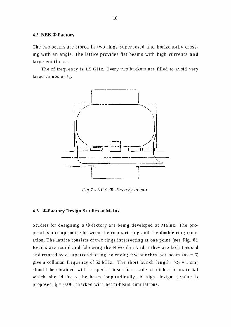
4.2 KEK Φ-Factory
The two beams are stored in two rings superposed and horizontally cross-
ing with an angle. The lattice provides flat beams with high currents and
large emittance.
The rf frequency is 1.5 GHz. Every two buckets are filled to avoid very
large values of εx.
Fig 7 - KEK Φ -Factory layout.
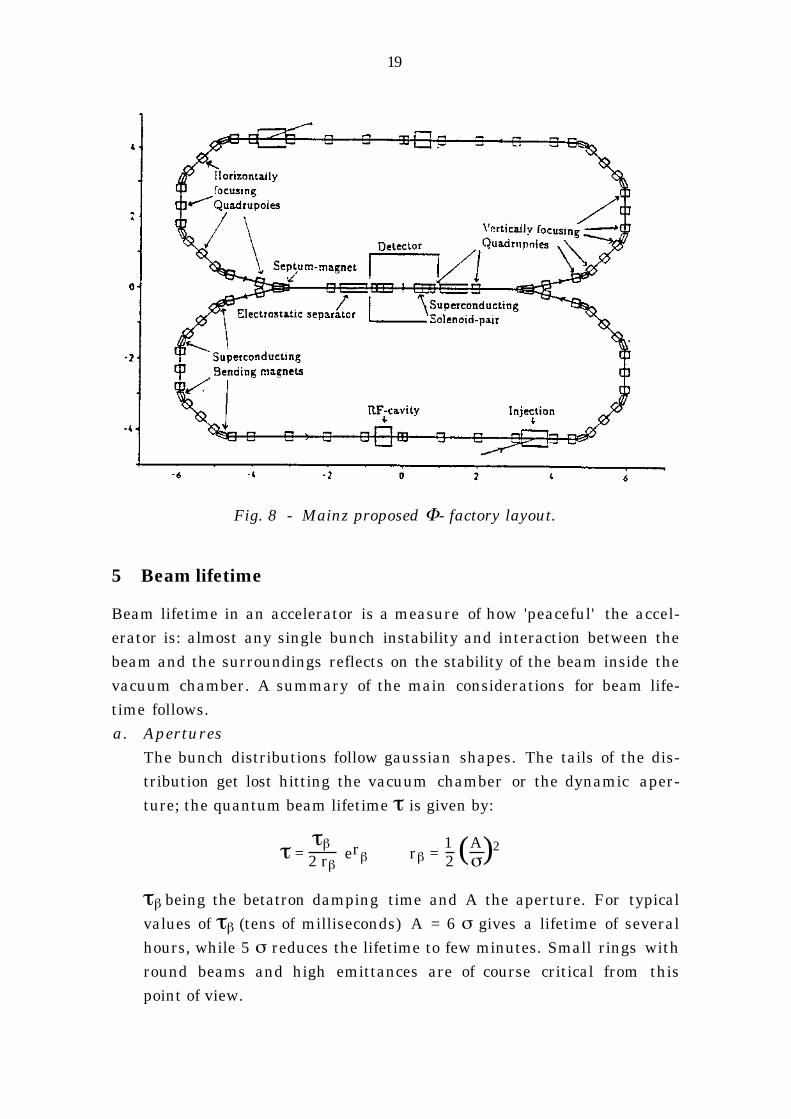
4.3 Φ-Factory Design Studies at Mainz
Studies for designing a Φ-factory are being developed at Mainz. The pro-
posal is a compromise between the compact ring and the double ring oper-
ation. The lattice consists of two rings intersecting at one point (see Fig. 8).
Beams are round and following the Novosibirsk idea they are both focused
and rotated by a superconducting solenoid; few bunches per beam (nb = 6)
give a collision frequency of 50 MHz. The short bunch length (σz = 1 cm)
should be obtained with a special insertion made of dielectric material
which should focus the beam longitudinally. A high design ξ value is
proposed: ξ = 0.08, checked with beam-beam simulations.
19
Fig. 8 - Mainz proposed Φ- factory layout.
5 Beam lifetime
Beam lifetime in an accelerator is a measure of how 'peaceful' the accel-erator is: almost any single bunch instability and interaction between thebeam and the surroundings reflects on the stability of the beam inside thevacuum chamber. A summary of the main considerations for beam life-time follows.a. Apertures
The bunch distributions follow gaussian shapes. The tails of the dis-tribution get lost hitting the vacuum chamber or the dynamic aper-ture; the quantum beam lifetime τ is given by:
τ = τβ2 rβ
erβ rβ = 12 (A
σ)2
τβ being the betatron damping time and A the aperture. For typicalvalues of τβ (tens of milliseconds) A = 6 σ gives a lifetime of severalhours, while 5 σ reduces the lifetime to few minutes. Small rings withround beams and high emittances are of course critical from thispoint of view.

20
b. Single bunch effects
- Touschek effect: when scattered particles inside the bunch get a
longitudinal momentum variation they can exceed the momen-
tum acceptance of the ring, or if the scattering occurs in a disper-
sive zone the induced horizontal oscillation can exceed the trans-
verse acceptance of the ring. This effect is very strong for low en-
ergy rings, especially for very flat beams because of its dependence
on the bunch density and is in fact the main limitation for
multibunch operation rings working with flat beams.
- Multiple Touschek effect: scattering between particles inside the
bunch transfers momentum between the planes to which can be
associated an increase in the transverse emittance which could
exceed the transverse acceptance, either physical or dynamic. I n
Φ-factories this effect is not of much concern because the emit-
tance is already large and its increment is only of few percent,
well contained in the ring acceptance.
c . Beam-gas interaction
The scattering between beam particles and residual gas molecules
can be elastic, producing betatron oscillations that can exceed the
transverse acceptance, or inelastic (bremsstrahlung), producing
energy oscillations exceeding the longitudinal acceptance.
Depends on vacuum and apertures: it is more demanding in small
rings because of the higher synchrotron radiation pressure.
d. Beam-beam bremsstrahlung
The beam-beam decay rate is proportional to L/(nb N). In single bunch
modes and at high luminosity the beam lifetime is reduced to few
minutes.
6 Injection
The total number of positrons required to obtain the quoted luminosity isvery high: 1011 ÷ 1012 for compact rings and ~ 1013 for double rings.Furthermore reliable operation asks for a short injection time, typicallyfew minutes for the double ring configuration, 1 minute for the compactring, to store the full current of both beams. It is clearly convenient toinject at full energy.
21
An accumulator, at the same energy of the main ring, is usually pro-posed to accumulate at lower frf to accept LINAC pulse. It is used also todamp the e+ emittance and energy spread to values acceptable by the mainring system and to equalize the two beam characteristics.
References
1. P.M. Ivanov et al, Luminosity and the Beam-Beam Effects on the Electron-PositronStorage Ring VEPP-2M with Superconducting Wiggler Magnet, Proceedings of the3rd Advanced ICFA Beam Dynamics Workshop, Novosibirsk, 1989, p. 26.
2. D.L. Rubin and L.A. Schick, Single Interaction Point of Operation of CESR, 1991Particle Accelerator Conference, San Francisco, USA, 1991, p.144.
3. J.T. Seeman, Observations of the Beam-beam Interaction, Nonlinear DynamicsAspects of Particle Accelerators, S. Margherita di Pula, Italy, 1985, Lecture Notes i nPhysics 247, p.121.
4. M. Bassetti, What are the Beam-beam limits in DAΦNE?, 1992, Unpublished.
5. L. Barkov et al., Novosibirsk Project of Φ-Meson Factory, Proceedings of Workshopon Physics and Detectors for DAΦNE - Frascati, April 9-12 1991, p.67.
6. A. Streun, Φ-Factory Studies at Mainz, Proceedings of Workshop on Physics andDetectors for DAΦNE - Frascati, April 9-12 1991, p.99.
7. A.N. Filippov et al., Proposal of the Round Beam Lattice for VEPP-2M Collider,Presented at the XVth International Conference on H.E.A., Hamburg, 1992.
8. C. Pellegrini, The UCLA Φ-Factory Project, Proceedings of Workshop on Physicsand Detectors for DAΦNE - Frascati, April 9-12 1991, p.83.
9. DAΦNE Project Team, DAΦNE Status Report, Proceedings of 3rd EPAC Conference -Berlin, 1992.
10. K. Hirata and K. Ohmi, Feasibility of a Φ-Factory in KEK, 1991 Particle AcceleratorConference, San Francisco, USA, 1991, p. 2847.
11. A. Piwinski, IEEE Trans. on Nucl. Scie. NS-24 , 1408 (1977).
12. A. Piwinski - "Synchro-betatron resonances" in Nonlinear Dynamics Aspects ofParticle Accelerators, S. Margherita di Pula, Italy, 1985, Lecture Notes in Physics247, p.104.
13. R.B. Palmer - SLAC - PUB - 4707 (1988).
14. K. Oide and Y. Yokoya, Phys. Rev. D40,315 (1989).
15. M. Bassetti and M.E. Biagini, private communication.
16. D.H. Rice, Beam-Beam Interaction: Experimental, AIP Conf. Proceedings 214,Berkeley 219 (1990).
17. M. Bassetti and C. Biscari, Beam-beam simulations with pc, unpublished.
18. P. Baldini et al. - DAΦNE Accelerating Cavity: R&D - Proceedings of 3rd EPACConference - Berlin, 24-28 March, 1992.
19. M. Bassetti et al - DAΦNE Longitudinal Feedback - Proceedings of 3rd EPACConference - Berlin, 24-28 March, 1992.