Battery Charger - · PDF fileSeries PB Construction 19“ Subrack 5000 -22000 Watt Types...
189
Catalogue Issue Battery Charger
Transcript of Battery Charger - · PDF fileSeries PB Construction 19“ Subrack 5000 -22000 Watt Types...
Catalogue
Issue 4
Battery Charger
vertrieb3
Schreibmaschinentext
vertrieb3
Schreibmaschinentext
vertrieb3
Schreibmaschinentext
vertrieb3
Schreibmaschinentext
vertrieb3
Schreibmaschinentext
vertrieb3
Schreibmaschinentext
vertrieb3
Schreibmaschinentext
List of Contents
Powertronic GmbH & Co. KG Phone: +49-(0)5223-18059-0 08/15 D-32278 Kirchlengern mail: [email protected]
Pages Series BP, Construction 19“ Cassette 150 – 350 Watt
Types / Dimensions / Technical Data 1-15
Series BP, Construction RM, Rail Mount 150 – 350 Watt
Types / Dimensions / Technical Data 16-38
Series BP, Construction CM, Chassis Mount 150 – 850 Watt
Types / Dimensions / Technical Data 39-69
Operating Principle 70-72 Operational Behavior 73-82 Series PB Construction 19“ Cassette 250 – 5000 Watt Types / Dimensions 83-108 Series PB Construction W, Wall Mount withTerminals 250 – 5000 Watt Types 109-120 Dimensions 121 Series PB 250-5000 Watt Technical Data 122-123 Fuses 124 Options 125-128 Series PB Construction 19“ Subrack 5000 -22000 Watt Types / Dimensions 129-145 Series PB Construction W, Mounting Plate with Terminals 6000 – 12000 Watt Types / Dimensions 146-156 Series PB 5000 -22000Watt Options electrical / mechanical 157-159 Series PSI 1200W Types / Dimensions / Technical Data 160-168 Series BC for use in Wind Turbines Types / Dimensions / Technical Data 169-186 This catalogue only serves for information, and hence, cannot constitute a component part of an offer or contract. In order to adapt the high quality of our products to technical progress, we reserve the right to change any and all specifications without prior notice. All data and illustrations are given without obligation.
Types BP300 – 19“ Cassette
Powertronic GmbH & Co. KG Phone: +49-(0)5223-18059 0 11/15 D-32278 Kirchlengern mail: [email protected]
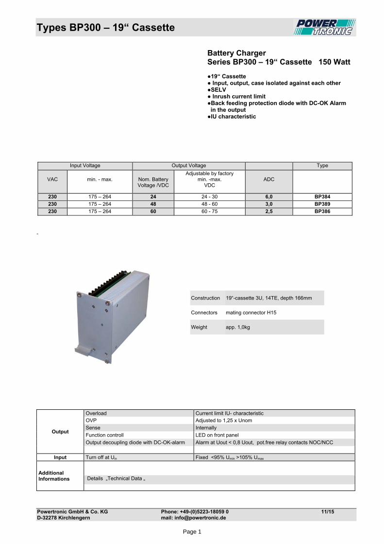
Battery Charger Series BP300 – 19“ Cassette 150 Watt 19“ Cassette Input, output, case isolated against each other SELV Inrush current limit Back feeding protection diode with DC-OK Alarm in the output IU characteristic
-
Construction 19“-cassette 3U, 14TE, depth 166mm
Connectors mating connector H15
Weight app. 1,0kg
Output
Overload Current limit IU- characteristic OVP Adjusted to 1,25 x Unom
Sense Internally
Function controll LED on front panel
Output decoupling diode with DC-OK-alarm Alarm at Uout < 0,8 Uout, pot.free relay contacts NOC/NCC
Input Turn off at Uin Fixed <95% Umin >105% Umax
Additional Informations
Details „Technical Data „
Input Voltage Output Voltage Type
VAC
min. - max.
Nom. Battery Voltage /VDC
Adjustable by factory min. -max.
VDC
ADC
230 175 – 264 24 24 - 30 6,0 BP384
230 175 – 264 48 48 - 60 3,0 BP389
230 175 – 264 60 60 - 75 2,5 BP386
Page 1
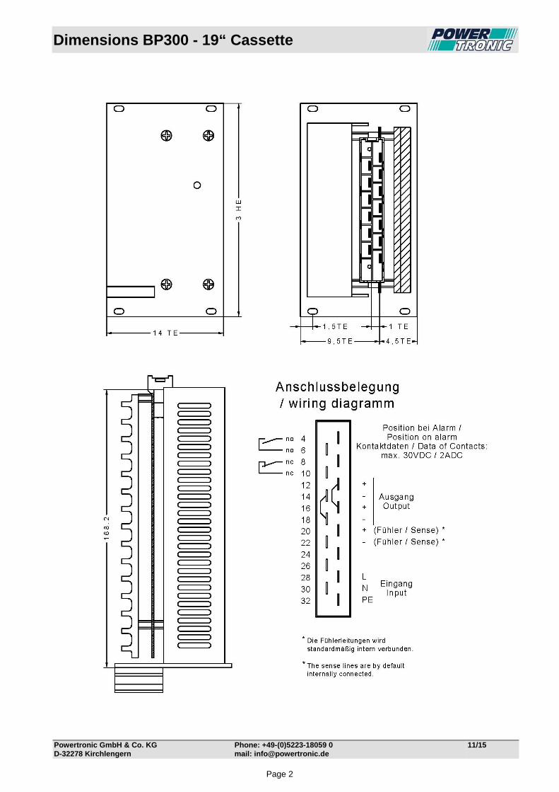
Dimensions BP300 - 19“ Cassette
Powertronic GmbH & Co. KG Phone: +49-(0)5223-18059 0 11/15 D-32278 Kirchlengern mail: [email protected]
Page 2
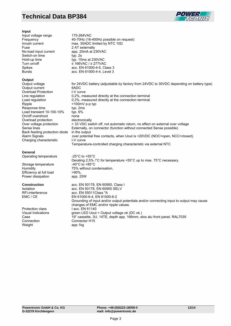
Technical Data BP384
Powertronic GmbH & Co. KG Phone: +49-(0)5223-18059-0 12/14 D-32278 Kirchlengern mail: [email protected]
Input Input voltage range 175-264VAC Frequency 40-70Hz (16-400Hz possible on request) Inrush current max. 35ADC limited by NTC 10Ω Fuse 2 AT externally No-load input current app. 20mA at 230VAC Switch-on time typ. 2s Hold-up time typ. 15ms at 230VAC Turn on/off ≤ 166VAC / ≥ 277VAC Spikes acc. EN 61000-4-5, Class 3 Bursts acc. EN 61000-4-4, Level 3 Output Output voltage for 24VDC battery (adjustable by factory from 24VDC to 30VDC depending on battery type) Output current 6ADC Overload Protection I-V curve Line regulation 0,2%, measured directly at the connection terminal Load regulation 0,3%, measured directly at the connection terminal Ripple <100mV p-p typ Response time typ. 2ms Load transient 10-100-10% typ. 6% On/off overshoot none Overload protection electronically Over voltage protection > 33 VDC switch off, not automatic return, no effect on external over voltage Sense lines Externally, on connector (function without connected Sense possible) Back feeding protection diode in the output Alarm Signals over potential free contacts, when Uout is <20VDC (NOC=open, NCC=closed). Charging characteristic I-V curve Temperature-controlled charging characteristic via external NTC General Operating temperature -25°C to +55°C Derating 2,5% /°C for temperature +55°C up to max. 75°C necessary. Storage temperature -40°C to +85°C Humidity 75% without condensation, Efficiency at full load ˃90%, Power dissipation app. 25W Construction acc. EN 50178, EN 60950, Class I Isolation acc. EN 50178, EN 60950 SELV RFI-interference acc. EN 55011Class "A EMC / CE EN 61000-6-4, EN 61000-6-2
Grounding of input and/or output potentials and/or connecting input to output may cause changes of EMC and/or ripple values.
Protection class I acc. EN 61140 Visual Indications green LED Uout = Output voltage ok (DC ok.) Case 19” cassette, 3U, 14TE, depth app. 166mm, elox alu front panel, RAL7035 Connection Connector H15 Weight app.1kg
Page 3

Technical Data BP389
Powertronic GmbH & Co. KG Phone: +49-(0)5223-18059-0 12/14 D-32278 Kirchlengern mail: [email protected]
Input Input voltage range 175-264VAC Frequency 40-70Hz (16-400Hz possible on request) Inrush current max. 35ADC limited by NTC 10Ω Fuse 2 AT externally No-load input current app. 20mA at 230VAC Switch-on time typ. 2s Hold-up time typ. 15ms at 230VAC Turn on/off ≤ 166VAC / ≥ 277VAC Spikes acc. EN 61000-4-5, Class 3 Bursts acc. EN 61000-4-4, Level 3 Output Output voltage for 48VDC battery (adjustable by factory from 48VDC to 60VDC depending on battery type) Output current 3ADC Overload Protection I-V curve Line regulation 0,2%, measured directly at the connection terminal Load regulation 0,3%, measured directly at the connection terminal Ripple <100mV p-p typ Response time typ. 2ms Load transient 10-100-10% typ. 6% On/off overshoot none Overload protection electronically Over voltage protection > 62VDC switch off, not automatic return, no effect on external over voltage Sense lines Externally, on connector (function without connected Sense possible) Back feeding protection diode in the output Alarm Signals over potential free contacts, when Uout is <40VDC (NOC=open, NCC=closed). Charging characteristic I-V curve Temperature-controlled charging characteristic via external NTC General Operating temperature -25°C to +55°C Derating 2,5% /°C for temperature +55°C up to max. 75°C necessary. Storage temperature -40°C to +85°C Humidity 75% without condensation, Efficiency at full load ˃90%, Power dissipation app. 25W Construction acc. EN 50178, EN 60950, Class I Isolation acc. EN 50178, EN 60950 SELV RFI-interference acc. EN 55011Class "A EMC / CE EN 61000-6-4, EN 61000-6-2
Grounding of input and/or output potentials and/or connecting input to output may cause changes of EMC and/or ripple values.
Protection class I acc. EN 61140 Visual Indications green LED Uout = Output voltage ok (DC ok.) Case 19” cassette, 3U, 14TE, depth app. 166mm, elox alu front panel, RAL7035 Connection Connector H15 Weight app. 1kg
Page 4

Technical Data BP386
Powertronic GmbH & Co. KG Phone: +49-(0)5223-18059-0 12/14 D-32278 Kirchlengern mail: [email protected]
Input Input voltage range 175-264VAC Frequency 40-70Hz (16-400Hz possible on request) Inrush current max. 35ADC limited by NTC 10Ω Fuse 2 AT externally No-load input current app. 20mA at 230VAC Switch-on time typ. 2s Hold-up time typ. 15ms at 230VAC Turn on/off ≤ 166VAC / ≥ 277VAC Spikes acc. EN 61000-4-5, Class 3 Bursts acc. EN 61000-4-4, Level 3 Output Output voltage for 60VDC battery (adjustable by factory from 60VDC to 75VDC depending on battery type) Output current 2,5ADC Overload Protection I-V curve Line regulation 0,2%, measured directly at the connection terminal Load regulation 0,3%, measured directly at the connection terminal Ripple <100mV p-p typ Response time typ. 2ms Load transient 10-100-10% typ. 6% On/off overshoot none Overload protection electronically Over voltage protection > 78VDC switch off, not automatic return, no effect on external over voltage Sense lines Externally, on connector (function without connected Sense possible) Back feeding protection diode in the output Alarm Signals over potential free contacts, when Uout is <50VDC (NOC=open, NCC=closed). Charging characteristic I-V curve Temperature-controlled charging characteristic via external NTC General Operating temperature -25°C to +55°C Derating 2,5% /°C for temperature +55°C up to max. 75°C necessary. Storage temperature -40°C to +85°C Humidity 75% without condensation, Efficiency at full load ˃90%, Power dissipation app. 25W Construction acc. EN 50178, EN 60950, Class I Isolation acc. EN 50178, EN 60950 SELV RFI-interference acc. EN 55011Class "A EMC / CE EN 61000-6-4, EN 61000-6-2
Grounding of input and/or output potentials and/or connecting input to output may cause changes of EMC and/or ripple values.
Protection class I acc. EN 61140 Visual Indications green LED Uout = Output voltage ok (DC ok.) Case 19” cassette, 3U, 14TE, depth app. 166mm, elox alu front panel, RAL7035 Connection Connector H15 Weight app. 1kg
Page 5
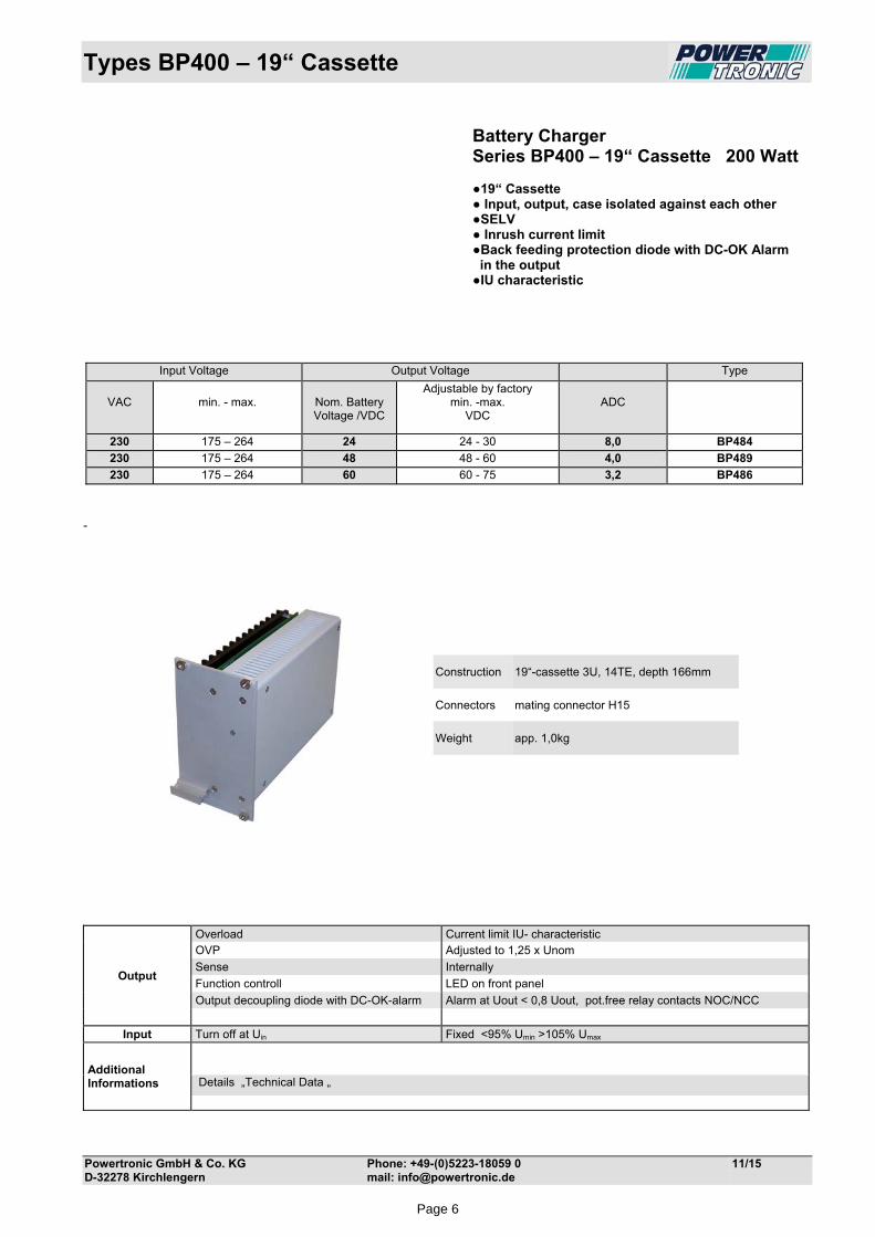
Types BP400 – 19“ Cassette
Powertronic GmbH & Co. KG Phone: +49-(0)5223-18059 0 11/15 D-32278 Kirchlengern mail: [email protected]
Battery Charger Series BP400 – 19“ Cassette 200 Watt 19“ Cassette Input, output, case isolated against each other SELV Inrush current limit Back feeding protection diode with DC-OK Alarm in the output IU characteristic
-
Construction 19“-cassette 3U, 14TE, depth 166mm
Connectors mating connector H15
Weight app. 1,0kg
Output
Overload Current limit IU- characteristic OVP Adjusted to 1,25 x Unom
Sense Internally
Function controll LED on front panel
Output decoupling diode with DC-OK-alarm Alarm at Uout < 0,8 Uout, pot.free relay contacts NOC/NCC
Input Turn off at Uin Fixed <95% Umin >105% Umax
Additional Informations
Details „Technical Data „
Input Voltage Output Voltage Type
VAC
min. - max.
Nom. Battery Voltage /VDC
Adjustable by factory min. -max.
VDC
ADC
230 175 – 264 24 24 - 30 8,0 BP484
230 175 – 264 48 48 - 60 4,0 BP489
230 175 – 264 60 60 - 75 3,2 BP486
Page 6
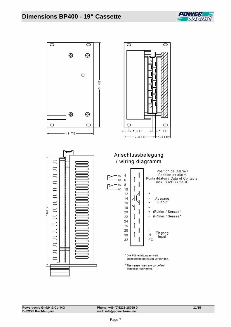
Dimensions BP400 - 19“ Cassette
Powertronic GmbH & Co. KG Phone: +49-(0)5223-18059 0 11/15 D-32278 Kirchlengern mail: [email protected]
Page 7

Technical Data BP484
Powertronic GmbH & Co. KG Phone: +49-(0)5223-18059-0 12/14 D-32278 Kirchlengern mail: [email protected]
Input Input voltage range 175-264VAC Frequency 40-70Hz (16-400Hz possible on request) Inrush current max. 35ADC limited by NTC 10Ω Fuse 2 AT externally No-load input current app. 20mA at 230VAC Switch-on time typ. 2s Hold-up time typ. 15ms at 230VAC Turn on/off ≤ 166VAC / ≥ 277VAC Spikes acc. EN 61000-4-5, Class 3 Bursts acc. EN 61000-4-4, Level 3 Output Output voltage for 24VDC battery (adjustable by factory from 24VDC to 30VDC depending on battery type) Output current 8ADC Overload Protection I-V curve Line regulation 0,2%, measured directly at the connection terminal Load regulation 0,3%, measured directly at the connection terminal Ripple <100mV p-p typ Response time typ. 2ms Load transient 10-100-10% typ. 6% On/off overshoot none Overload protection electronically Over voltage protection > 33 VDC switch off, not automatic return, no effect on external over voltage Sense lines Externally, on connector (function without connected Sense possible) Back feeding protection diode in the output Alarm Signals over potential free contacts, when Uout is <20VDC (NOC=open, NCC=closed). Charging characteristic I-V curve Temperature-controlled charging characteristic via external NTC General Operating temperature -25°C to +55°C Derating 2,5% /°C for temperature +55°C up to max. 75°C necessary. Storage temperature -40°C to +85°C Humidity 75% without condensation, Efficiency at full load ˃90%, Power dissipation app. 28W Construction acc. EN 50178, EN 60950, Class I Isolation acc. EN 50178, EN 60950 SELV RFI-interference acc. EN 55011Class "A EMC / CE EN 61000-6-4, EN 61000-6-2
Grounding of input and/or output potentials and/or connecting input to output may cause changes of EMC and/or ripple values.
Protection class I acc. EN 61140 Visual Indications green LED Uout = Output voltage ok (DC ok.) Case 19” cassette, 3U, 14TE, depth app. 166mm, elox alu front panel, RAL7035 Connection Connector H15 Weight app. 1kg
Page 8

Technical Data BP489
Powertronic GmbH & Co. KG Phone: +49-(0)5223-18059-0 12/14 D-32278 Kirchlengern mail: [email protected]
Input Input voltage range 175-264VAC Frequency 40-70Hz (16-400Hz possible on request) Inrush current max. 35ADC limited by NTC 10Ω Fuse 2 AT externally No-load input current app. 20mA at 230VAC Switch-on time typ. 2s Hold-up time typ. 15ms at 230VAC Turn on/off ≤ 166VAC / ≥ 277VAC Spikes acc. EN 61000-4-5, Class 3 Bursts acc. EN 61000-4-4, Level 3 Output Output voltage for 48VDC battery (adjustable by factory from 48VDC to 60VDC depending on battery type) Output current 4ADC Overload Protection I-V curve Line regulation 0,2%, measured directly at the connection terminal Load regulation 0,3%, measured directly at the connection terminal Ripple <100mV p-p typ Response time typ. 2ms Load transient 10-100-10% typ. 6% On/off overshoot none Overload protection electronically Over voltage protection > 62VDC switch off, not automatic return, no effect on external over voltage Sense lines Externally, on connector (function without connected Sense possible) Back feeding protection diode in the output Alarm Signals over potential free contacts, when Uout is <40VDC (NOC=open, NCC=closed). Charging characteristic I-V curve Temperature-controlled charging characteristic via external NTC General Operating temperature -25°C to +55°C Derating 2,5% /°C for temperature +55°C up to max. 75°C necessary. Storage temperature -40°C to +85°C Humidity 75% without condensation, Efficiency at full load ˃90%, Power dissipation app. 28W Construction acc. EN 50178, EN 60950, Class I Isolation acc. EN 50178, EN 60950 SELV RFI-interference acc. EN 55011Class "A EMC / CE EN 61000-6-4, EN 61000-6-2
Grounding of input and/or output potentials and/or connecting input to output may cause changes of EMC and/or ripple values.
Protection class I acc. EN 61140 Visual Indications green LED Uout = Output voltage ok (DC ok.) Case 19” cassette, 3U, 14TE, depth app. 166mm, elox alu front panel, RAL7035 Connection Connector H15 Weight app. 1kg
Page 9

Technical Data BP486
Powertronic GmbH & Co. KG Phone: +49-(0)5223-18059-0 12/14 D-32278 Kirchlengern mail: [email protected]
Input Input voltage range 175-264VAC Frequency 40-70Hz (16-400Hz possible on request) Inrush current max. 35ADC limited by NTC 10Ω Fuse 2 AT externally No-load input current app. 20mA at 230VAC Switch-on time typ. 2s Hold-up time typ. 15ms at 230VAC Turn on/off ≤ 166VAC / ≥ 277VAC Spikes acc. EN 61000-4-5, Class 3 Bursts acc. EN 61000-4-4, Level 3 Output Output voltage for 60VDC battery (adjustable by factory from 60VDC to 75VDC depending on battery type) Output current 3,2ADC Overload Protection I-V curve Line regulation 0,2%, measured directly at the connection terminal Load regulation 0,3%, measured directly at the connection terminal Ripple <100mV p-p typ Response time typ. 2ms Load transient 10-100-10% typ. 6% On/off overshoot none Overload protection electronically Over voltage protection > 78VDC switch off, not automatic return, no effect on external over voltage Sense lines Externally, on connector (function without connected Sense possible) Back feeding protection diode in the output Alarm Signals over potential free contacts, when Uout is <50VDC (NOC=open, NCC=closed). Charging characteristic I-V curve Temperature-controlled charging characteristic via external NTC General Operating temperature -25°C to +55°C Derating 2,5% /°C for temperature +55°C up to max. 75°C necessary. Storage temperature -40°C to +85°C Humidity 75% without condensation, Efficiency at full load ˃90%, Power dissipation app. 28W Construction acc. EN 50178, EN 60950, Class I Isolation acc. EN 50178, EN 60950 SELV RFI-interference acc. EN 55011Class "A EMC / CE EN 61000-6-4, EN 61000-6-2
Grounding of input and/or output potentials and/or connecting input to output may cause changes of EMC and/or ripple values.
Protection class I acc. EN 61140 Visual Indications green LED Uout = Output voltage ok (DC ok.) Case 19” cassette, 3U, 14TE, depth app. 166mm, elox alu front panel, RAL7035 Connection Connector H15 Weight app. 1kg
Page 10
Types BP500 – 19“ Cassette
Powertronic GmbH & Co. KG Phone: +49-(0)5223-18059 0 11/15 D-32278 Kirchlengern mail: [email protected]
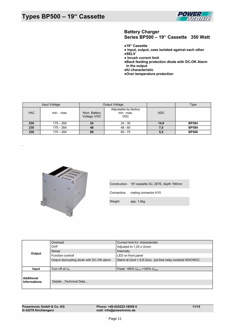
Battery Charger Series BP500 – 19“ Cassette 350 Watt 19“ Cassette Input, output, case isolated against each other SELV Inrush current limit Back feeding protection diode with DC-OK Alarm in the output IU characteristic Over temperature protection
-
Construction 19“-cassette 3U, 28TE, depth 166mm
Connectors mating connector H15
Weight app. 1,0kg
Output
Overload Current limit IU- characteristic OVP Adjusted to 1,25 x Unom
Sense Internally
Function controll LED on front panel
Output decoupling diode with DC-OK-alarm Alarm at Uout < 0,8 Uout, pot.free relay contacts NOC/NCC
Input Turn off at Uin Fixed <95% Umin >105% Umax
Additional Informations
Details „Technical Data „
Input Voltage Output Voltage Type
VAC
min. - max.
Nom. Battery Voltage /VDC
Adjustable by factory min. -max.
VDC
ADC
230 175 – 264 24 24 - 30 14,0 BP584
230 175 – 264 48 48 - 60 7,0 BP589
230 175 – 264 60 60 - 75 5,5 BP586
Page 11
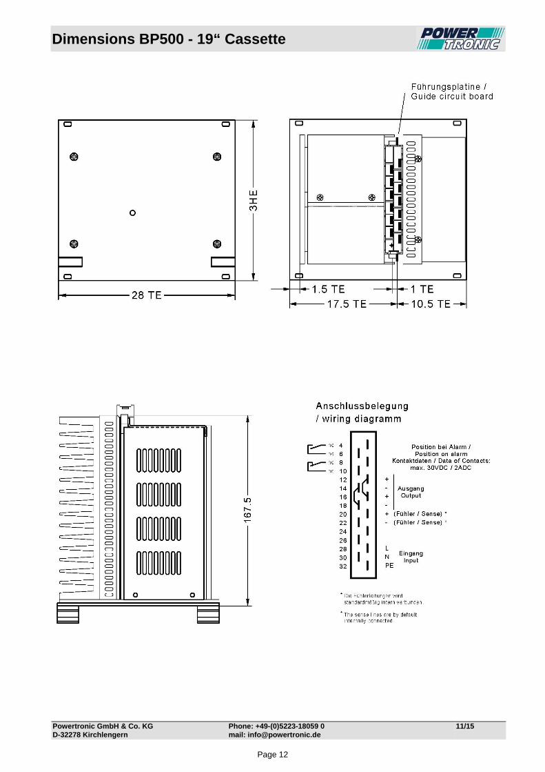
Dimensions BP500 - 19“ Cassette
Powertronic GmbH & Co. KG Phone: +49-(0)5223-18059 0 11/15 D-32278 Kirchlengern mail: [email protected]
Page 12
Technical Data BP584
Powertronic GmbH & Co. KG Phone: +49-(0)5223-18059-0 12/14 D-32278 Kirchlengern mail: [email protected]
Input Input voltage range 175-264VAC Frequency 40-70Hz (16-400Hz possible on request) Inrush current max. 35ADC limited by NTC 10Ω Fuse 6,3 AT externally No-load input current app. 25mA at 230VAC Switch-on time typ. 2s Hold-up time typ. 15ms at 230VAC Turn on/off ≤ 166VAC / ≥ 277VAC Spikes acc. EN 61000-4-5, Class 3 Bursts acc. EN 61000-4-4, Level 3 Output Output voltage for 24VDC battery (adjustable by factory from 24VDC to 30VDC depending on battery type) Output current 14ADC Overload Protection I-V curve Line regulation 0,2%, measured directly at the connection terminal Load regulation 0,3%, measured directly at the connection terminal Ripple <100mV p-p typ Response time typ. 2ms Load transient 10-100-10% typ. 6% On/off overshoot none Overload protection electronically Over voltage protection > 33 VDC switch off, not automatic return, no effect on external over voltage Sense lines Externally, on connector (function without connected Sense possible) Back feeding protection diode in the output Alarm Signals over potential free contacts, when Uout is <20VDC (NOC=open, NCC=closed). Charging characteristic I-V curve Temperature-controlled charging characteristic via external NTC General Operating temperature -25°C to +55°C Derating 2,5% /°C for temperature +55°C up to max. 75°C necessary. Over temperature protection unit switch off if internally temperature is too high, automatically switch on after cooling Storage temperature -40°C to +85°C Humidity 75% without condensation, Efficiency at full load ˃90%, Power dissipation app. 68W Over temperature protection shut off, at hot spot off about 100°C. Automatically restart after cooling down. Construction acc. EN 50178, EN 60950, Class I Isolation acc. EN 50178, EN 60950 SELV RFI-interference acc. EN 55011Class "A EMC / CE EN 61000-6-4, EN 61000-6-2
Grounding of input and/or output potentials and/or connecting input to output may cause changes of EMC and/or ripple values.
Protection class I acc. EN 61140 Visual Indications green LED Uout = Output voltage ok (DC ok.) Case 19” cassette, 3U, 28TE, depth app. 166mm, elox alu front panel, RAL7035 Connection Connector H15 Weight app. 1kg
Page 13

Technical Data BP589
Powertronic GmbH & Co. KG Phone: +49-(0)5223-18059-0 12/14 D-32278 Kirchlengern mail: [email protected]
Input Input voltage range 175-264VAC Frequency 40-70Hz (16-400Hz possible on request) Inrush current max. 35ADC limited by NTC 10Ω Fuse 6,3 AT externally No-load input current app. 25mA at 230VAC Switch-on time typ. 2s Hold-up time typ. 15ms at 230VAC Turn on/off ≤ 166VAC / ≥ 277VAC Spikes acc. EN 61000-4-5, Class 3 Bursts acc. EN 61000-4-4, Level 3 Output Output voltage for 48VDC battery (adjustable by factory from 48VDC to 60VDC depending on battery type) Output current 7ADC Overload Protection I-V curve Line regulation 0,2%, measured directly at the connection terminal Load regulation 0,3%, measured directly at the connection terminal Ripple <100mV p-p typ Response time typ. 2ms Load transient 10-100-10% typ. 6% On/off overshoot none Overload protection electronically Over voltage protection > 62VDC switch off, not automatic return, no effect on external over voltage Sense lines Externally, on connector (function without connected Sense possible) Back feeding protection diode in the output Alarm Signals over potential free contacts, when Uout is <40VDC (NOC=open, NCC=closed). Charging characteristic I-V curve Temperature-controlled charging characteristic via external NTC General Operating temperature -25°C to +55°C Derating 2,5% /°C for temperature +55°C up to max. 75°C necessary. Over temperature protection unit switch off if internally temperature is too high, automatically switch on after cooling Storage temperature -40°C to +85°C Humidity 75% without condensation, Efficiency at full load ˃90%, Power dissipation app. 68W Over temperature protection shut off, at hot spot off about 100°C. Automatically restart after cooling down. Construction acc. EN 50178, EN 60950, Class I Isolation acc. EN 50178, EN 60950 SELV RFI-interference acc. EN 55011Class "A EMC / CE EN 61000-6-4, EN 61000-6-2
Grounding of input and/or output potentials and/or connecting input to output may cause changes of EMC and/or ripple values.
Protection class I acc. EN 61140 Visual Indications green LED Uout = Output voltage ok (DC ok.) Case 19” cassette, 3U, 28TE, depth app. 166mm, elox alu front panel, RAL7035 Connection Connector H15 Weight app. 1kg
Page 14

Technical Data BP586
Powertronic GmbH & Co. KG Phone: +49-(0)5223-18059-0 12/14 D-32278 Kirchlengern mail: [email protected]
Input Input voltage range 175-264VAC Frequency 40-70Hz (16-400Hz possible on request) Inrush current max. 35ADC limited by NTC 10Ω Fuse 6,3 AT externally No-load input current app. 25mA at 230VAC Switch-on time typ. 2s Hold-up time typ. 15ms at 230VAC Turn on/off ≤ 166VAC / ≥ 277VAC Spikes acc. EN 61000-4-5, Class 3 Bursts acc. EN 61000-4-4, Level 3 Output Output voltage for 60VDC battery (adjustable by factory from 60VDC to 75VDC depending on battery type) Output current 5,5ADC Overload Protection I-V curve Line regulation 0,2%, measured directly at the connection terminal Load regulation 0,3%, measured directly at the connection terminal Ripple <100mV p-p typ Response time typ. 2ms Load transient 10-100-10% typ. 6% On/off overshoot none Overload protection electronically Over voltage protection > 78VDC switch off, not automatic return, no effect on external over voltage Sense lines Externally, on connector (function without connected Sense possible) Back feeding protection diode in the output Alarm Signals over potential free contacts, when Uout is <50VDC (NOC=open, NCC=closed). Charging characteristic I-V curve Temperature-controlled charging characteristic via external NTC General Operating temperature -25°C to +55°C Derating 2,5% /°C for temperature +55°C up to max. 75°C necessary. Over temperature protection unit switch off if internally temperature is too high, automatically switch on after cooling Storage temperature -40°C to +85°C Humidity 75% without condensation, Efficiency at full load ˃90%, Power dissipation app. 68W Over temperature protection shut off, at hot spot off about 100°C. Automatically restart after cooling down. Construction acc. EN 50178, EN 60950, Class I Isolation acc. EN 50178, EN 60950 SELV RFI-interference acc. EN 55011Class "A EMC / CE EN 61000-6-4, EN 61000-6-2
Grounding of input and/or output potentials and/or connecting input to output may cause changes of EMC and/or ripple values.
Protection class I acc. EN 61140 Visual Indications green LED Uout = Output voltage ok (DC ok.) Case 19” cassette, 3U, 28TE, depth app. 166mm, elox alu front panel, RAL7035 Connection Connector H15 Weight app. 1kg
Page 15
Types BP300RM – Rail Mount
Powertronic GmbH & Co. KG Phone: +49-(0)5223-18059 0 11/15 D-32278 Kirchlengern mail: [email protected]
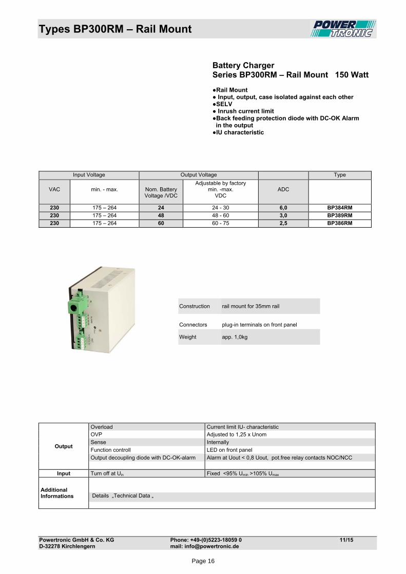
Battery Charger Series BP300RM – Rail Mount 150 Watt Rail Mount Input, output, case isolated against each other SELV Inrush current limit Back feeding protection diode with DC-OK Alarm in the output IU characteristic
Construction rail mount for 35mm rail
Connectors
plug-in terminals on front panel
Weight app. 1,0kg
Output
Overload Current limit IU- characteristic OVP Adjusted to 1,25 x Unom
Sense Internally
Function controll LED on front panel
Output decoupling diode with DC-OK-alarm Alarm at Uout < 0,8 Uout, pot.free relay contacts NOC/NCC
Input Turn off at Uin Fixed <95% Umin >105% Umax
Additional Informations
Details „Technical Data „
Input Voltage Output Voltage Type
VAC
min. - max.
Nom. Battery Voltage /VDC
Adjustable by factory min. -max.
VDC
ADC
230 175 – 264 24 24 - 30 6,0 BP384RM
230 175 – 264 48 48 - 60 3,0 BP389RM
230 175 – 264 60 60 - 75 2,5 BP386RM
Page 16
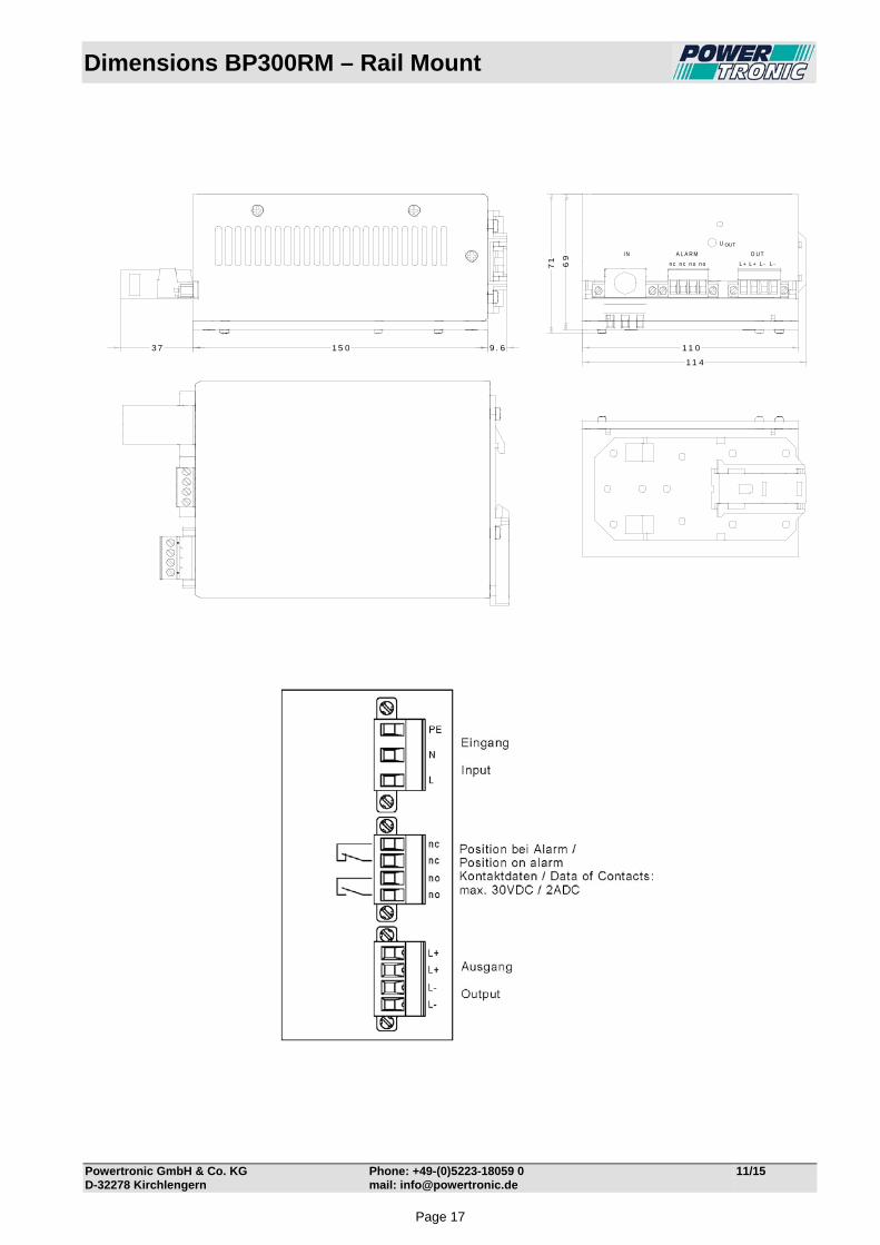
Dimensions BP300RM – Rail Mount
Powertronic GmbH & Co. KG Phone: +49-(0)5223-18059 0 11/15 D-32278 Kirchlengern mail: [email protected]
n c n c n o n o L + L + L - L -
I N A L A R M O U T
U OUT
1 1 0
1 1 4
1 5 0 9 . 63 7
69
71
Page 17

Technical Data BP384RM
Powertronic GmbH & Co. KG Phone: +49-(0)5223-18059-0 12/14 D-32278 Kirchlengern mail: [email protected]
Input Input voltage range 175-264VAC Frequency 40-70Hz (16-400Hz possible on request) Inrush current max. 35ADC limited by NTC 10Ω Fuse 2 AT externally No-load input current app. 20mA at 230VAC Switch-on time typ. 2s Hold-up time typ. 15ms at 230VAC Turn on/off ≤ 166VAC / ≥ 277VAC Spikes acc. EN 61000-4-5, Class 3 Bursts acc. EN 61000-4-4, Level 3 Output Output voltage for 24VDC battery (adjustable by factory from 24VDC to 30VDC depending on battery type) Output current 6ADC Overload Protection I-V curve Line regulation 0,2%, measured directly at the connection terminal Load regulation 0,3%, measured directly at the connection terminal Ripple <100mV p-p typ Response time typ. 2ms Load transient 10-100-10% typ. 6% On/off overshoot none Overload protection electronically Over voltage protection > 33 VDC switch off, not automatic return, no effect on external over voltage Sense lines connected externally Back feeding protection diode in the output Alarm Signals over potential free contacts, when Uout is <20VDC (NOC=open, NCC=closed). Charging characteristic I-V curve Temperature-controlled charging characteristic via external NTC General Operating temperature -25°C to +55°C Derating 2,5% /°C for temperature +55°C up to max. 75°C necessary. Storage temperature -40°C to +85°C Humidity 75% without condensation, Efficiency at full load ˃90%, Power dissipation app. 25W Construction acc. EN 50178, EN 60950, Class I Isolation acc. EN 50178, EN 60950 SELV RFI-interference acc. EN 55011Class "A EMC / CE EN 61000-6-4, EN 61000-6-2
Grounding of input and/or output potentials and/or connecting input to output may cause changes of EMC and/or ripple values.
Protection class I acc. EN 61140 Visual Indications green LED Uout = Output voltage ok (DC ok.) Case for rail mount, 35mm rail EN50022, Alu varnished, RAL7035 Connection plug-in terminals on front panel Weight app. 1kg
Page 18

Technical Data BP389RM
Powertronic GmbH & Co. KG Phone: +49-(0)5223-18059-0 12/14 D-32278 Kirchlengern mail: [email protected]
Input Input voltage range 175-264VAC Frequency 40-70Hz (16-400Hz possible on request) Inrush current max. 35ADC limited by NTC 10Ω Fuse 2 AT externally No-load input current app. 20mA at 230VAC Switch-on time typ. 2s Hold-up time typ. 15ms at 230VAC Turn on/off ≤ 166VAC / ≥ 277VAC Spikes acc. EN 61000-4-5, Class 3 Bursts acc. EN 61000-4-4, Level 3 Output Output voltage for 48VDC battery (adjustable by factory from 48VDC to 60VDC depending on battery type) Output current 3ADC Overload Protection I-V curve Line regulation 0,2%, measured directly at the connection terminal Load regulation 0,3%, measured directly at the connection terminal Ripple <100mV p-p typ Response time typ. 2ms Load transient 10-100-10% typ. 6% On/off overshoot none Overload protection electronically Over voltage protection > 62VDC switch off, not automatic return, no effect on external over voltage Back feeding protection diode in the output Alarm Signals over potential free contacts, when Uout is <40VDC (NOC=open, NCC=closed). Charging characteristic I-V curve Temperature-controlled charging characteristic via external NTC General Operating temperature -25°C to +55°C Derating 2,5% /°C for temperature +55°C up to max. 75°C necessary. Storage temperature -40°C to +85°C Humidity 75% without condensation, Efficiency at full load ˃90%, Power dissipation app. 25W Construction acc. EN 50178, EN 60950, Class I Isolation acc. EN 50178, EN 60950 SELV RFI-interference acc. EN 55011Class "A EMC / CE EN 61000-6-4, EN 61000-6-2
Grounding of input and/or output potentials and/or connecting input to output may cause changes of EMC and/or ripple values.
Protection class I acc. EN 61140 Visual Indications green LED Uout = Output voltage ok (DC ok.) Case for rail mount, 35mm rail EN50022, Alu varnished, RAL7035 Connection plug-in terminals on front panel Weight app. 1kg
Page 19

Technical Data BP386RM
Powertronic GmbH & Co. KG Phone: +49-(0)5223-18059-0 12/14 D-32278 Kirchlengern mail: [email protected]
Input Input voltage range 175-264VAC Frequency 40-70Hz (16-400Hz possible on request) Inrush current max. 35ADC limited by NTC 10Ω Fuse 2 AT externally No-load input current app. 20mA at 230VAC Switch-on time typ. 2s Hold-up time typ. 15ms at 230VAC Turn on/off ≤ 166VAC / ≥ 277VAC Spikes acc. EN 61000-4-5, Class 3 Bursts acc. EN 61000-4-4, Level 3 Output Output voltage for 60VDC battery (adjustable by factory from 60VDC to 75VDC depending on battery type) Output current 2,5ADC Overload Protection I-V curve Line regulation 0,2%, measured directly at the connection terminal Load regulation 0,3%, measured directly at the connection terminal Ripple <100mV p-p typ Response time typ. 2ms Load transient 10-100-10% typ. 6% On/off overshoot none Overload protection electronically Over voltage protection > 78VDC switch off, not automatic return, no effect on external over voltage Back feeding protection diode in the output Alarm Signals over potential free contacts, when Uout is <50VDC (NOC=open, NCC=closed). Charging characteristic I-V curve Temperature-controlled charging characteristic via external NTC General Operating temperature -25°C to +55°C Derating 2,5% /°C for temperature +55°C up to max. 75°C necessary. Storage temperature -40°C to +85°C Humidity 75% without condensation, Efficiency at full load ˃90%, Power dissipation app. 25W Construction acc. EN 50178, EN 60950, Class I Isolation acc. EN 50178, EN 60950 SELV RFI-interference acc. EN 55011Class "A EMC / CE EN 61000-6-4, EN 61000-6-2
Grounding of input and/or output potentials and/or connecting input to output may cause changes of EMC and/or ripple values.
Protection class I acc. EN 61140 Visual Indications green LED Uout = Output voltage ok (DC ok.) Case for rail mount, 35mm rail EN50022, Alu varnished, RAL7035 Connection plug-in terminals on front panel Weight app. 1kg
Page 20
Types BP400RM – Rail Mount
Powertronic GmbH & Co. KG Phone: +49-(0)5223-18059 0 11/15 D-32278 Kirchlengern mail: [email protected]
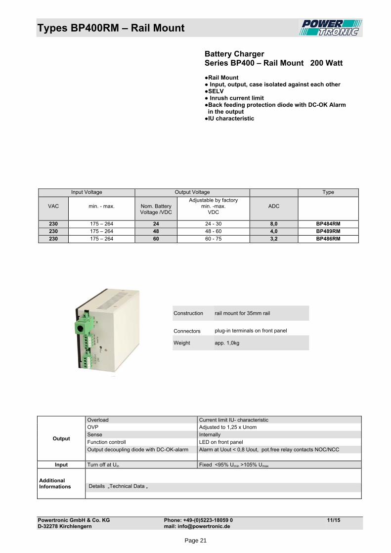
Battery Charger Series BP400 – Rail Mount 200 Watt Rail Mount Input, output, case isolated against each other SELV Inrush current limit Back feeding protection diode with DC-OK Alarm in the output IU characteristic
Output
Overload Current limit IU- characteristic OVP Adjusted to 1,25 x Unom
Sense Internally
Function controll LED on front panel
Output decoupling diode with DC-OK-alarm Alarm at Uout < 0,8 Uout, pot.free relay contacts NOC/NCC
Input Turn off at Uin Fixed <95% Umin >105% Umax
Additional Informations
Details „Technical Data „
Input Voltage Output Voltage Type
VAC
min. - max.
Nom. Battery Voltage /VDC
Adjustable by factory min. -max.
VDC
ADC
230 175 – 264 24 24 - 30 8,0 BP484RM
230 175 – 264 48 48 - 60 4,0 BP489RM
230 175 – 264 60 60 - 75 3,2 BP486RM
Construction rail mount for 35mm rail
Connectors
plug-in terminals on front panel
Weight app. 1,0kg
Page 21
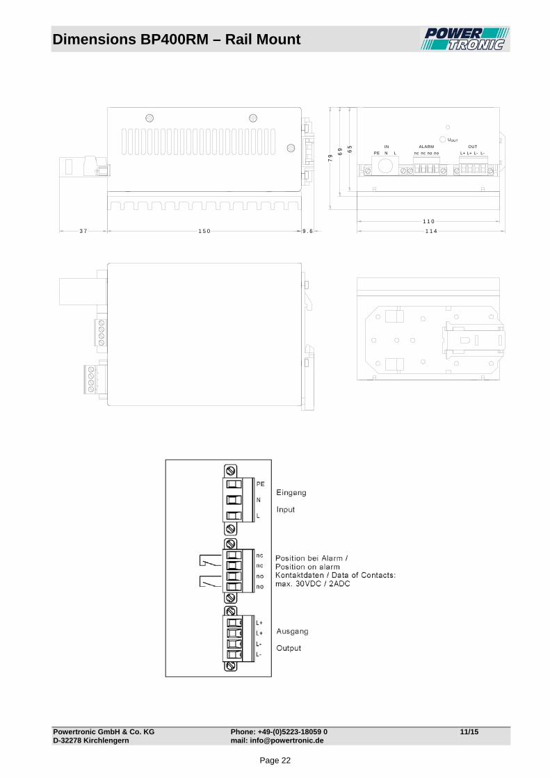
Dimensions BP400RM – Rail Mount
Powertronic GmbH & Co. KG Phone: +49-(0)5223-18059 0 11/15 D-32278 Kirchlengern mail: [email protected]
PE N L nc nc no no L+ L+ L- L-
IN ALARM OUT
UOUT
1 1 41 5 0 9 . 63 7
65
79
1 1 0
69
Page 22
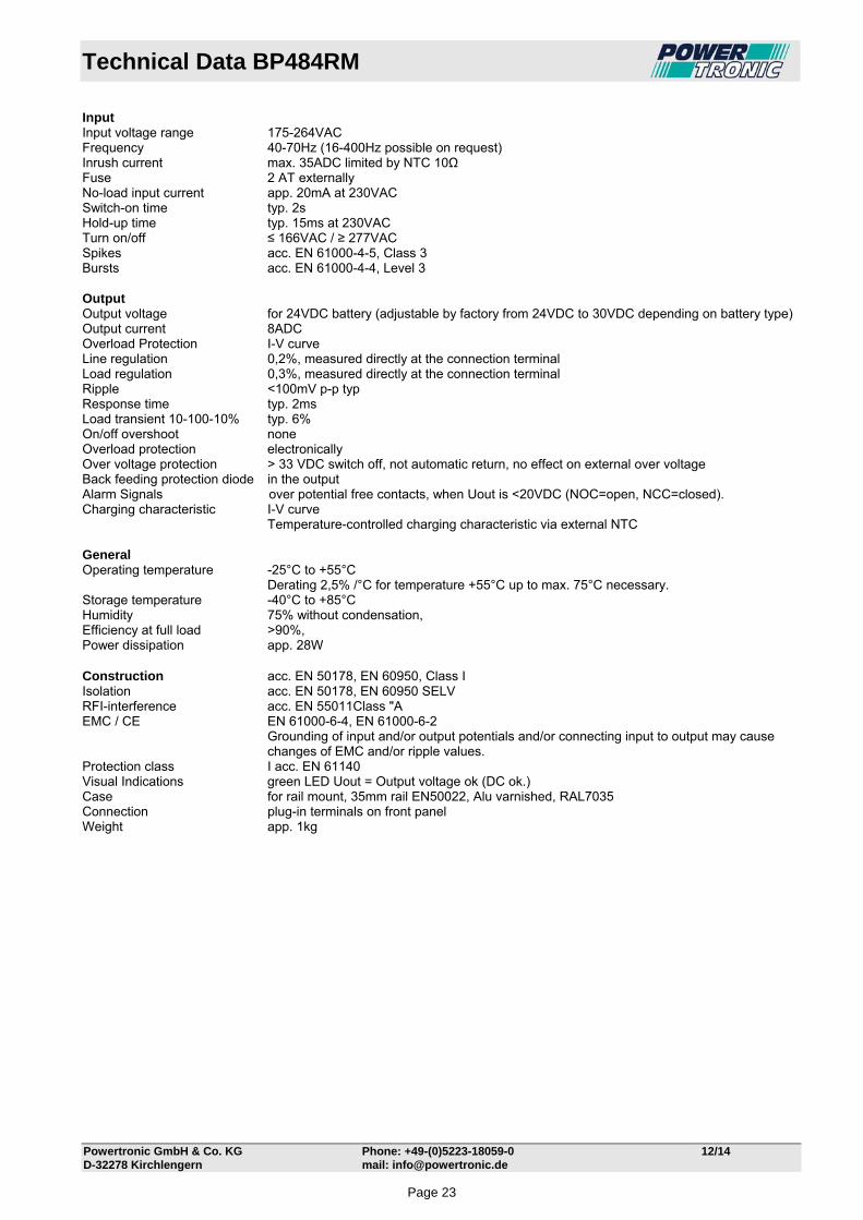
Technical Data BP484RM
Powertronic GmbH & Co. KG Phone: +49-(0)5223-18059-0 12/14 D-32278 Kirchlengern mail: [email protected]
Input Input voltage range 175-264VAC Frequency 40-70Hz (16-400Hz possible on request) Inrush current max. 35ADC limited by NTC 10Ω Fuse 2 AT externally No-load input current app. 20mA at 230VAC Switch-on time typ. 2s Hold-up time typ. 15ms at 230VAC Turn on/off ≤ 166VAC / ≥ 277VAC Spikes acc. EN 61000-4-5, Class 3 Bursts acc. EN 61000-4-4, Level 3 Output Output voltage for 24VDC battery (adjustable by factory from 24VDC to 30VDC depending on battery type) Output current 8ADC Overload Protection I-V curve Line regulation 0,2%, measured directly at the connection terminal Load regulation 0,3%, measured directly at the connection terminal Ripple <100mV p-p typ Response time typ. 2ms Load transient 10-100-10% typ. 6% On/off overshoot none Overload protection electronically Over voltage protection > 33 VDC switch off, not automatic return, no effect on external over voltage Back feeding protection diode in the output Alarm Signals over potential free contacts, when Uout is <20VDC (NOC=open, NCC=closed). Charging characteristic I-V curve Temperature-controlled charging characteristic via external NTC General Operating temperature -25°C to +55°C Derating 2,5% /°C for temperature +55°C up to max. 75°C necessary. Storage temperature -40°C to +85°C Humidity 75% without condensation, Efficiency at full load ˃90%, Power dissipation app. 28W Construction acc. EN 50178, EN 60950, Class I Isolation acc. EN 50178, EN 60950 SELV RFI-interference acc. EN 55011Class "A EMC / CE EN 61000-6-4, EN 61000-6-2
Grounding of input and/or output potentials and/or connecting input to output may cause changes of EMC and/or ripple values.
Protection class I acc. EN 61140 Visual Indications green LED Uout = Output voltage ok (DC ok.) Case for rail mount, 35mm rail EN50022, Alu varnished, RAL7035 Connection plug-in terminals on front panel Weight app. 1kg
Page 23

Technical Data BP489RM
Powertronic GmbH & Co. KG Phone: +49-(0)5223-18059-0 12/14 D-32278 Kirchlengern mail: [email protected]
Input Input voltage range 175-264VAC Frequency 40-70Hz (16-400Hz possible on request) Inrush current max. 35ADC limited by NTC 10Ω Fuse 2 AT externally No-load input current app. 20mA at 230VAC Switch-on time typ. 2s Hold-up time typ. 15ms at 230VAC Turn on/off ≤ 166VAC / ≥ 277VAC Spikes acc. EN 61000-4-5, Class 3 Bursts acc. EN 61000-4-4, Level 3 Output Output voltage for 48VDC battery (adjustable by factory from 48VDC to 60VDC depending on battery type) Output current 4ADC Overload Protection I-V curve Line regulation 0,2%, measured directly at the connection terminal Load regulation 0,3%, measured directly at the connection terminal Ripple <100mV p-p typ Response time typ. 2ms Load transient 10-100-10% typ. 6% On/off overshoot none Overload protection electronically Over voltage protection > 62VDC switch off, not automatic return, no effect on external over voltage Back feeding protection diode in the output Alarm Signals over potential free contacts, when Uout is <40VDC (NOC=open, NCC=closed). Charging characteristic I-V curve Temperature-controlled charging characteristic via external NTC General Operating temperature -25°C to +55°C Derating 2,5% /°C for temperature +55°C up to max. 75°C necessary. Storage temperature -40°C to +85°C Humidity 75% without condensation, Efficiency at full load ˃90%, Power dissipation app. 28W Construction acc. EN 50178, EN 60950, Class I Isolation acc. EN 50178, EN 60950 SELV RFI-interference acc. EN 55011Class "A EMC / CE EN 61000-6-4, EN 61000-6-2
Grounding of input and/or output potentials and/or connecting input to output may cause changes of EMC and/or ripple values.
Protection class I acc. EN 61140 Visual Indications green LED Uout = Output voltage ok (DC ok.) Case for rail mount, 35mm rail EN50022, Alu varnished, RAL7035 Connection plug-in terminals on front panel Weight app. 1kg
Page 24

Technical Data BP486RM
Powertronic GmbH & Co. KG Phone: +49-(0)5223-18059-0 12/14 D-32278 Kirchlengern mail: [email protected]
Input Input voltage range 175-264VAC Frequency 40-70Hz (16-400Hz possible on request) Inrush current max. 35ADC limited by NTC 10Ω Fuse 2 AT externally No-load input current app. 20mA at 230VAC Switch-on time typ. 2s Hold-up time typ. 15ms at 230VAC Turn on/off ≤ 166VAC / ≥ 277VAC Spikes acc. EN 61000-4-5, Class 3 Bursts acc. EN 61000-4-4, Level 3 Output Output voltage for 60VDC battery (adjustable by factory from 60VDC to 75VDC depending on battery type) Output current 3,2ADC Overload Protection I-V curve Line regulation 0,2%, measured directly at the connection terminal Load regulation 0,3%, measured directly at the connection terminal Ripple <100mV p-p typ Response time typ. 2ms Load transient 10-100-10% typ. 6% On/off overshoot none Overload protection electronically Over voltage protection > 78VDC switch off, not automatic return, no effect on external over voltage Back feeding protection diode in the output Alarm Signals over potential free contacts, when Uout is <50VDC (NOC=open, NCC=closed). Charging characteristic I-V curve Temperature-controlled charging characteristic via external NTC General Operating temperature -25°C to +55°C Derating 2,5% /°C for temperature +55°C up to max. 75°C necessary. Storage temperature -40°C to +85°C Humidity 75% without condensation, Efficiency at full load ˃90%, Power dissipation app. 28W Construction acc. EN 50178, EN 60950, Class I Isolation acc. EN 50178, EN 60950 SELV RFI-interference acc. EN 55011Class "A EMC / CE EN 61000-6-4, EN 61000-6-2
Grounding of input and/or output potentials and/or connecting input to output may cause changes of EMC and/or ripple values.
Protection class I acc. EN 61140 Visual Indications green LED Uout = Output voltage ok (DC ok.) Case for rail mount, 35mm rail EN50022, Alu varnished, RAL7035 Connection plug-in terminals on front panel Weight app. 1kg
Page 25
Types BP500RM – Rail Mount
Powertronic GmbH & Co. KG Phone: +49-(0)5223-18059 0 11/15 D-32278 Kirchlengern mail: [email protected]
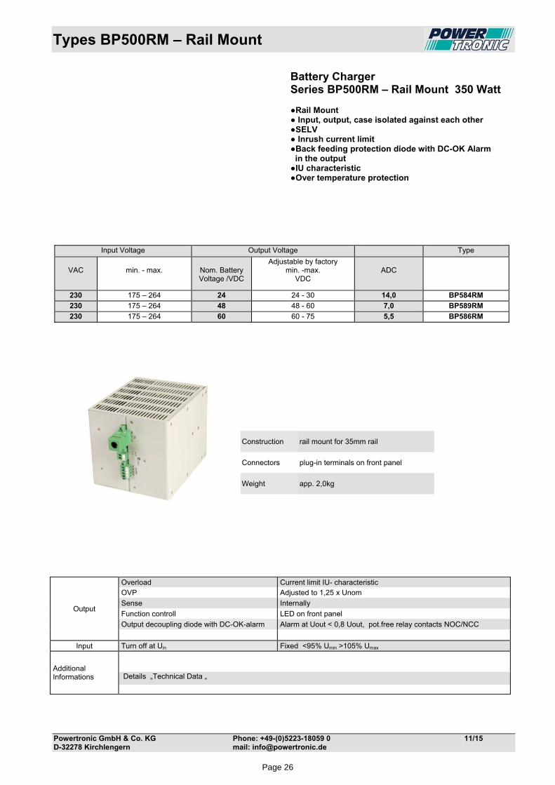
Battery Charger Series BP500RM – Rail Mount 350 Watt Rail Mount Input, output, case isolated against each other SELV Inrush current limit Back feeding protection diode with DC-OK Alarm in the output IU characteristic Over temperature protection
Construction rail mount for 35mm rail
Connectors plug-in terminals on front panel
Weight app. 2,0kg
Output
Overload Current limit IU- characteristic OVP Adjusted to 1,25 x Unom
Sense Internally
Function controll LED on front panel
Output decoupling diode with DC-OK-alarm Alarm at Uout < 0,8 Uout, pot.free relay contacts NOC/NCC
Input Turn off at Uin Fixed <95% Umin >105% Umax
Additional Informations
Details „Technical Data „
Input Voltage Output Voltage Type
VAC
min. - max.
Nom. Battery Voltage /VDC
Adjustable by factory min. -max.
VDC
ADC
230 175 – 264 24 24 - 30 14,0 BP584RM
230 175 – 264 48 48 - 60 7,0 BP589RM
230 175 – 264 60 60 - 75 5,5 BP586RM
Page 26
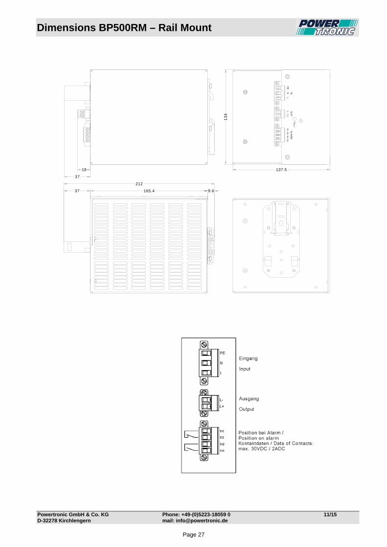
Dimensions BP500RM – Rail Mount
Powertronic GmbH & Co. KG Phone: +49-(0)5223-18059 0 11/15 D-32278 Kirchlengern mail: [email protected]
PE
NL
L-
L+
nc
nc
no
no
UO
UT
INO
UT
AL
AR
M
13
4
137.518
37
165.4 9.637
212
Page 27

Technical Data BP584RM
Powertronic GmbH & Co. KG Phone: +49-(0)5223-18059-0 12/14 D-32278 Kirchlengern mail: [email protected]
Input Input voltage range 175-264VAC Frequency 40-70Hz (16-400Hz possible on request) Inrush current max. 35ADC limited by NTC 10Ω Fuse 6,3 AT externally No-load input current app. 25mA at 230VAC Switch-on time typ. 2s Hold-up time typ. 15ms at 230VAC Turn on/off ≤ 166VAC / ≥ 277VAC Spikes acc. EN 61000-4-5, Class 3 Bursts acc. EN 61000-4-4, Level 3 Output Output voltage for 24VDC battery (adjustable by factory from 24VDC to 30VDC depending on battery type) Output current 14ADC Overload Protection I-V curve Line regulation 0,2%, measured directly at the connection terminal Load regulation 0,3%, measured directly at the connection terminal Ripple <100mV p-p typ Response time typ. 2ms Load transient 10-100-10% typ. 6% On/off overshoot none Overload protection electronically Over voltage protection > 33 VDC switch off, not automatic return, no effect on external over voltage Back feeding protection diode in the output Alarm Signals over potential free contacts, when Uout is <20VDC (NOC=open, NCC=closed). Charging characteristic I-V curve Temperature-controlled charging characteristic via external NTC General Operating temperature -25°C to +55°C Derating 2,5% /°C for temperature +55°C up to max. 75°C necessary. Over temperature protection unit switch off if internally temperature is too high, automatically switch on after cooling Storage temperature -40°C to +85°C Humidity 75% without condensation, Efficiency at full load ˃90%, Power dissipation app. 68W Over temperature protection shut off, at hot spot off about 100°C. Automatically restart after cooling down. Construction acc. EN 50178, EN 60950, Class I Isolation acc. EN 50178, EN 60950 SELV RFI-interference acc. EN 55011Class "A EMC / CE EN 61000-6-4, EN 61000-6-2
Grounding of input and/or output potentials and/or connecting input to output may cause changes of EMC and/or ripple values.
Protection class I acc. EN 61140 Visual Indications green LED Uout = Output voltage ok (DC ok.) Case for rail mount, 35mm rail EN50022, Alu varnished, RAL7035 Connection plug-in terminals on front panel Weight app. 2kg
Page 28

Technical Data BP589RM
Powertronic GmbH & Co. KG Phone: +49-(0)5223-18059-0 12/14 D-32278 Kirchlengern mail: [email protected]
Input Input voltage range 175-264VAC Frequency 40-70Hz (16-400Hz possible on request) Inrush current max. 35ADC limited by NTC 10Ω Fuse 6,3 AT externally No-load input current app. 25mA at 230VAC Switch-on time typ. 2s Hold-up time typ. 15ms at 230VAC Turn on/off ≤ 166VAC / ≥ 277VAC Spikes acc. EN 61000-4-5, Class 3 Bursts acc. EN 61000-4-4, Level 3 Output Output voltage for 48VDC battery (adjustable by factory from 48VDC to 60VDC depending on battery type) Output current 7ADC Overload Protection I-V curve Line regulation 0,2%, measured directly at the connection terminal Load regulation 0,3%, measured directly at the connection terminal Ripple <100mV p-p typ Response time typ. 2ms Load transient 10-100-10% typ. 6% On/off overshoot none Overload protection electronically Over voltage protection > 62VDC switch off, not automatic return, no effect on external over voltage Back feeding protection diode in the output Alarm Signals over potential free contacts, when Uout is <40VDC (NOC=open, NCC=closed). Charging characteristic I-V curve Temperature-controlled charging characteristic via external NTC General Operating temperature -25°C to +55°C Derating 2,5% /°C for temperature +55°C up to max. 75°C necessary. Over temperature protection unit switch off if internally temperature is too high, automatically switch on after cooling Storage temperature -40°C to +85°C Humidity 75% without condensation, Efficiency at full load ˃90%, Power dissipation app. 68W Over temperature protection shut off, at hot spot off about 100°C. Automatically restart after cooling down. Construction acc. EN 50178, EN 60950, Class I Isolation acc. EN 50178, EN 60950 SELV RFI-interference acc. EN 55011Class "A EMC / CE EN 61000-6-4, EN 61000-6-2
Grounding of input and/or output potentials and/or connecting input to output may cause changes of EMC and/or ripple values.
Protection class I acc. EN 61140 Visual Indications green LED Uout = Output voltage ok (DC ok.) Case for rail mount, 35mm rail EN50022, Alu varnished, RAL7035 Connection plug-in terminals on front panel Weight app. 2kg
Page 1Page 29

Technical Data BP586RM
Powertronic GmbH & Co. KG Phone: +49-(0)5223-18059-0 12/14 D-32278 Kirchlengern mail: [email protected]
Input Input voltage range 175-264VAC Frequency 40-70Hz (16-400Hz possible on request) Inrush current max. 35ADC limited by NTC 10Ω Fuse 6,3 AT externally No-load input current app. 25mA at 230VAC Switch-on time typ. 2s Hold-up time typ. 15ms at 230VAC Turn on/off ≤ 166VAC / ≥ 277VAC Spikes acc. EN 61000-4-5, Class 3 Bursts acc. EN 61000-4-4, Level 3 Output Output voltage for 60VDC battery (adjustable by factory from 60VDC to 75VDC depending on battery type) Output current 5,5ADC Overload Protection I-V curve Line regulation 0,2%, measured directly at the connection terminal Load regulation 0,3%, measured directly at the connection terminal Ripple <100mV p-p typ Response time typ. 2ms Load transient 10-100-10% typ. 6% On/off overshoot none Overload protection electronically Over voltage protection > 78VDC switch off, not automatic return, no effect on external over voltage Back feeding protection diode in the output Alarm Signals over potential free contacts, when Uout is <50VDC (NOC=open, NCC=closed). Charging characteristic I-V curve Temperature-controlled charging characteristic via external NTC General Operating temperature -25°C to +55°C Derating 2,5% /°C for temperature +55°C up to max. 75°C necessary. Over temperature protection unit switch off if internally temperature is too high, automatically switch on after cooling Storage temperature -40°C to +85°C Humidity 75% without condensation, Efficiency at full load ˃90%, Power dissipation app. 68W Over temperature protection shut off, at hot spot off about 100°C. Automatically restart after cooling down. Construction acc. EN 50178, EN 60950, Class I Isolation acc. EN 50178, EN 60950 SELV RFI-interference acc. EN 55011Class "A EMC / CE EN 61000-6-4, EN 61000-6-2
Grounding of input and/or output potentials and/or connecting input to output may cause changes of EMC and/or ripple values.
Protection class I acc. EN 61140 Visual Indications green LED Uout = Output voltage ok (DC ok.) Case for rail mount, 35mm rail EN50022, Alu varnished RAL7035 Connection plug-in terminals on front panel Weight app. 2kg
Page 2Page 30
Types BP1500RM – Rail Mount
Powertronic GmbH & Co. KG Phone: +49-(0)5223-18059 0 09/14 D-32278 Kirchlengern mail: [email protected]
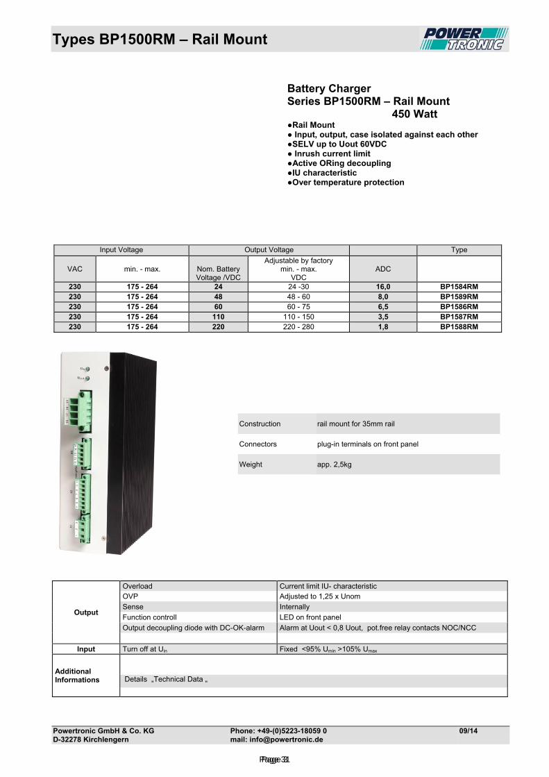
Battery Charger Series BP1500RM – Rail Mount 450 Watt Rail Mount Input, output, case isolated against each other SELV up to Uout 60VDC Inrush current limit Active ORing decoupling IU characteristic Over temperature protection
Construction rail mount for 35mm rail
Connectors plug-in terminals on front panel
Weight app. 2,5kg
Output
Overload Current limit IU- characteristic OVP Adjusted to 1,25 x Unom
Sense Internally
Function controll LED on front panel
Output decoupling diode with DC-OK-alarm Alarm at Uout < 0,8 Uout, pot.free relay contacts NOC/NCC
Input Turn off at Uin Fixed <95% Umin >105% Umax
Additional Informations
Details „Technical Data „
Input Voltage Output Voltage Type
VAC
min. - max.
Nom. Battery Voltage /VDC
Adjustable by factory min. - max.
VDC
ADC
230 175 - 264 24 24 -30 16,0 BP1584RM 230 175 - 264 48 48 - 60 8,0 BP1589RM 230 175 - 264 60 60 - 75 6,5 BP1586RM 230 175 - 264 110 110 - 150 3,5 BP1587RM 230 175 - 264 220 220 - 280 1,8 BP1588RM
Page 3Page 31
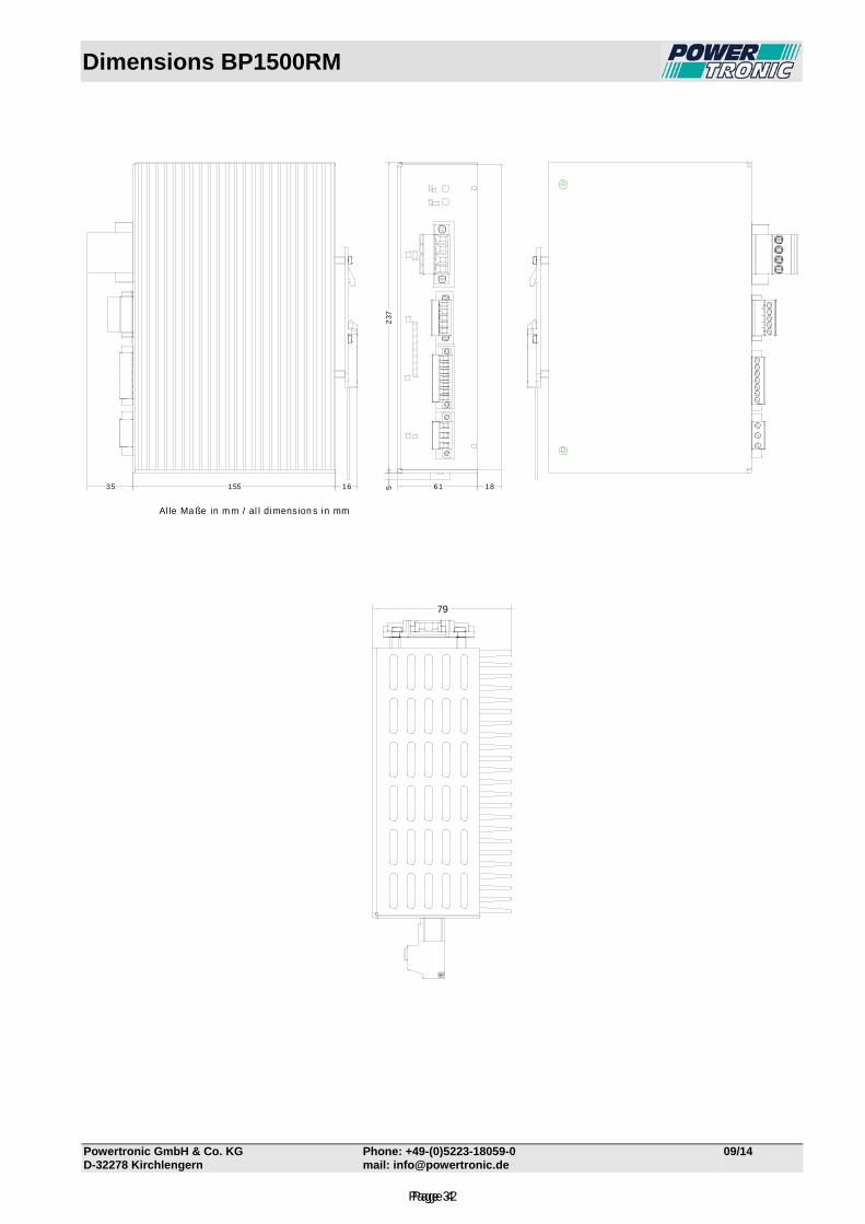
Dimensions BP1500RM
Powertronic GmbH & Co. KG Phone: +49-(0)5223-18059-0 09/14 D-32278 Kirchlengern mail: [email protected]
155 1635 61 18
237
5
Al le Ma ße in mm / al l dimension s in mm
79
Page 4Page 32

Connection Diagram
Powertronic GmbH & Co. KG Phone: +49-(0)5223-18059-0 11/15 D-32278 Kirchlengern mail: [email protected]
Series BP1500
Page 5Page 33

Technical Data BP1584RM
Powertronic GmbH & Co. KG Phone: +49-(0)5223-18059-0 12/14 D-32278 Kirchlengern mail: [email protected]
Input Input voltage range 175-264VAC Frequency 40-70Hz (16-400Hz possible on request) Inrush current max. 35ADC limited by NTC 10Ω Fuse 10 AT externally No-load input current app. 30mA at 230VAC Switch-on time typ. 2s Hold-up time typ. 15ms at 230VAC Turn on/off ≤ 166VAC / ≥ 277VAC Spikes acc. EN 61000-4-5, Class 3 Bursts acc. EN 61000-4-4, Level 3 Output Output voltage for 24VDC battery (adjustable by factory from 24VDC to 30VDC depending on battery type) Output current 14ADC Overload Protection I-V curve Line regulation 0,2%, measured directly at the connection terminal Load regulation 0,3%, measured directly at the connection terminal Ripple <100mV p-p typ Response time typ. 2ms Load transient 10-100-10% typ. 6% On/off overshoot none Overload protection electronically Over voltage protection > 33 VDC switch off, not automatic return, no effect on external over voltage Sense lines Externally, on connector (function without connected Sense possible) Parallel-/redundant active ORing decoupling. The ORing FET can be monitored Connection the current sharing for 2 units will be approx. 30/70% Active current sharing using the active current sharing in a parallel connection, the communication between the
units is done by the use of a current share bus. Thereby a current symmetry off < 1.5A can be achieved. It’s possible to connect up to 4 units in parallel. The length of the interconnec-tion wire does not exceed 1m.
Alarm Signals over potential free contacts, when Uout is <20VDC (NOC=open, NCC=closed). Charging characteristic I-V curve Temperature-controlled charging characteristic via external NTC Boost charge via external remote control voltage General Operating temperature -25°C to +55°C Derating 2,5% /°C for temperature +55°C up to max. 75°C necessary. Over temperature protection unit switch off if internally temperature is too high, automatically switch on after cooling Storage temperature -40°C to +85°C Humidity 75% without condensation, Efficiency at full load ˃90%, Power dissipation app. 88W Over temperature protection shut off, at hot spot off about 100°C. Automatically restart after cooling down. Construction acc. EN 50178, EN 60950, Class I Isolation acc. EN 50178, EN 60950 SELV RFI-interference acc. EN 55011Class "A EMC / CE EN 61000-6-4, EN 61000-6-2
Grounding of input and/or output potentials and/or connecting input to output may cause changes of EMC and/or ripple values.
Protection class I acc. EN 61140 Visual Indications green LED Uin = Input voltage on green LED Uout = Output voltage ok (DC ok.) Case for rail mount, 35mm rail EN50022, Alu varnished, RAL7035 Connection plug-in terminals on front panel Weight app. 2,5kg
Page 6Page 34

Technical Data BP1589RM
Powertronic GmbH & Co. KG Phone: +49-(0)5223-18059-0 12/14 D-32278 Kirchlengern mail: [email protected]
Input Input voltage range 175-264VAC Frequency 40-70Hz (16-400Hz possible on request) Inrush current max. 35ADC limited by NTC 10Ω Fuse 10 AT externally No-load input current app. 30mA at 230VAC Switch-on time typ. 2s Hold-up time typ. 15ms at 230VAC Turn on/off ≤ 166VAC / ≥ 277VAC Spikes acc. EN 61000-4-5, Class 3 Bursts acc. EN 61000-4-4, Level 3 Output Output voltage for 48VDC battery (adjustable by factory from 48VDC to 60VDC depending on battery type) Output current 8,0ADC Overload Protection I-V curve Line regulation 0,2%, measured directly at the connection terminal Load regulation 0,3%, measured directly at the connection terminal Ripple <100mV p-p typ Response time typ. 2ms Load transient 10-100-10% typ. 6% On/off overshoot none Overload protection electronically Over voltage protection > 62VDC switch off, not automatic return, no effect on external over voltage Sense lines Externally, on connector (function without connected Sense possible) Parallel-/redundant active ORing decoupling. The ORing FET can be monitored Connection the current sharing for 2 units will be approx. 30/70% Active current sharing using the active current sharing in a parallel connection, the communication between the
units is done by the use of a current share bus. Thereby a current symmetry off < 1.5A can be achieved. It’s possible to connect up to 4 units in parallel. The length of the interconnec-tion wire does not exceed 1m.
Alarm Signals over potential free contacts, when Uout is <40VDC (NOC=open, NCC=closed). Charging characteristic I-V curve Temperature-controlled charging characteristic via external NTC Boost charge via external remote control voltage General Operating temperature -25°C to +55°C Derating 2,5% /°C for temperature +55°C up to max. 75°C necessary. Over temperature protection unit switch off if internally temperature is too high, automatically switch on after cooling Storage temperature -40°C to +85°C Humidity 75% without condensation, Efficiency at full load ˃90%, Power dissipation app. 88W Over temperature protection shut off, at hot spot off about 100°C. Automatically restart after cooling down. Construction acc. EN 50178, EN 60950, Class I Isolation acc. EN 50178, EN 60950 SELV RFI-interference acc. EN 55011Class "A EMC / CE EN 61000-6-4, EN 61000-6-2
Grounding of input and/or output potentials and/or connecting input to output may cause changes of EMC and/or ripple values.
Protection class I acc. EN 61140 Visual Indications green LED Uin = Input voltage on green LED Uout = Output voltage ok (DC ok.) Case for rail mount, 35mm rail EN50022, Alu varnished, RAL7035 Connection plug-in terminals on front panel Weight app. 2,5kg
Page 7Page 35

Technical Data BP1586RM
Powertronic GmbH & Co. KG Phone: +49-(0)5223-18059-0 09/14 D-32278 Kirchlengern mail: [email protected]
Input Input voltage range 175-264VAC Frequency 40-70Hz (16-400Hz possible on request) Inrush current max. 35ADC limited by NTC 10Ω Fuse 10 AT externally No-load input current app. 30mA at 230VAC Switch-on time typ. 2s Hold-up time typ. 15ms at 230VAC Turn on/off ≤ 166VAC / ≥ 277VAC Spikes acc. EN 61000-4-5, Class 3 Bursts acc. EN 61000-4-4, Level 3 Output Output voltage for 60VDC battery (adjustable by factory from 60VDC to 75VDC depending on battery type) Output current 6,5ADC Overload Protection I-V curve Line regulation 0,2%, measured directly at the connection terminal Load regulation 0,3%, measured directly at the connection terminal Ripple <100mV p-p typ Response time typ. 2ms Load transient 10-100-10% typ. 6% On/off overshoot none Overload protection electronically Over voltage protection > 78VDC switch off, not automatic return, no effect on external over voltage Sense lines Externally, on connector (function without connected Sense possible) Parallel-/redundant active ORing decoupling. The ORing FET can be monitored Connection the current sharing for 2 units will be approx. 30/70% Active current sharing using the active current sharing in a parallel connection, the communication between the
units is done by the use of a current share bus. Thereby a current symmetry off < 1.5A can be achieved. It’s possible to connect up to 4 units in parallel. The length of the interconnec-tion wire does not exceed 1m.
Alarm Signals over potential free contacts, when Uout is <50VDC (NOC=open, NCC=closed). Charging characteristic I-V curve Temperature-controlled charging characteristic via external NTC Boost charge via external remote control voltage General Operating temperature -25°C to +55°C Derating 2,5% /°C for temperature +55°C up to max. 75°C necessary. Over temperature protection unit switch off if internally temperature is too high, automatically switch on after cooling Storage temperature -40°C to +85°C Humidity 75% without condensation, Efficiency at full load ˃90%, Power dissipation app. 88W Over temperature protection shut off, at hot spot off about 100°C. Automatically restart after cooling down. Construction acc. EN 50178, EN 60950, Class I Isolation acc. EN 50178, EN 60950 SELV RFI-interference acc. EN 55011Class "A EMC / CE EN 61000-6-4, EN 61000-6-2
Grounding of input and/or output potentials and/or connecting input to output may cause changes of EMC and/or ripple values.
Protection class I acc. EN 61140 Visual Indications green LED Uin = Input voltage on green LED Uout = Output voltage ok (DC ok.) Case for rail mount, 35mm rail EN50022, Alu varnished, RAL7035 Connection plug-in terminals on front panel Weight app. 2,5kg
Page 8Page 36
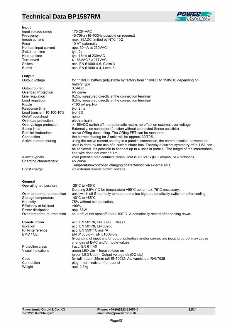
Technical Data BP1587RM
Powertronic GmbH & Co. KG Phone: +49-(0)5223-18059-0 12/14 D-32278 Kirchlengern mail: [email protected]
Input Input voltage range 175-264VAC Frequency 40-70Hz (16-400Hz possible on request) Inrush current max. 35ADC limited by NTC 10Ω Fuse 10 AT externally No-load input current app. 30mA at 230VAC Switch-on time typ. 2s Hold-up time typ. 15ms at 230VAC Turn on/off ≤ 166VAC / ≥ 277VAC Spikes acc. EN 61000-4-5, Class 3 Bursts acc. EN 61000-4-4, Level 3 Output Output voltage for 110VDC battery (adjustable by factory from 110VDC to 150VDC depending on battery type) Output current 3,5ADC Overload Protection I-V curve Line regulation 0,2%, measured directly at the connection terminal Load regulation 0,3%, measured directly at the connection terminal Ripple <100mV p-p typ Response time typ. 2ms Load transient 10-100-10% typ. 6% On/off overshoot none Overload protection electronically Over voltage protection > 155VDC switch off, not automatic return, no effect on external over voltage Sense lines Externally, on connector (function without connected Sense possible) Parallel-/redundant active ORing decoupling. The ORing FET can be monitored Connection the current sharing for 2 units will be approx. 30/70% Active current sharing using the active current sharing in a parallel connection, the communication between the
units is done by the use of a current share bus. Thereby a current symmetry off < 1.5A can be achieved. It’s possible to connect up to 4 units in parallel. The length of the interconnec-tion wire does not exceed 1m.
Alarm Signals over potential free contacts, when Uout is <90VDC (NOC=open, NCC=closed). Charging characteristic I-V curve Temperature-controlled charging characteristic via external NTC Boost charge via external remote control voltage General Operating temperature -25°C to +55°C Derating 2,5% /°C for temperature +55°C up to max. 75°C necessary. Over temperature protection unit switch off if internally temperature is too high, automatically switch on after cooling Storage temperature -40°C to +85°C Humidity 75% without condensation, Efficiency at full load ˃90%, Power dissipation app. 88W Over temperature protection shut off, at hot spot off about 100°C. Automatically restart after cooling down. Construction acc. EN 50178, EN 60950, Class I Isolation acc. EN 50178, EN 60950 RFI-interference acc. EN 55011Class "A EMC / CE EN 61000-6-4, EN 61000-6-2
Grounding of input and/or output potentials and/or connecting input to output may cause changes of EMC and/or ripple values.
Protection class I acc. EN 61140 Visual Indications green LED Uin = Input voltage on green LED Uout = Output voltage ok (DC ok.) Case for rail mount, 35mm rail EN50022, Alu varnished, RAL7035 Connection plug-in terminals on front panel Weight app. 2,5kg
Page 9Page 37
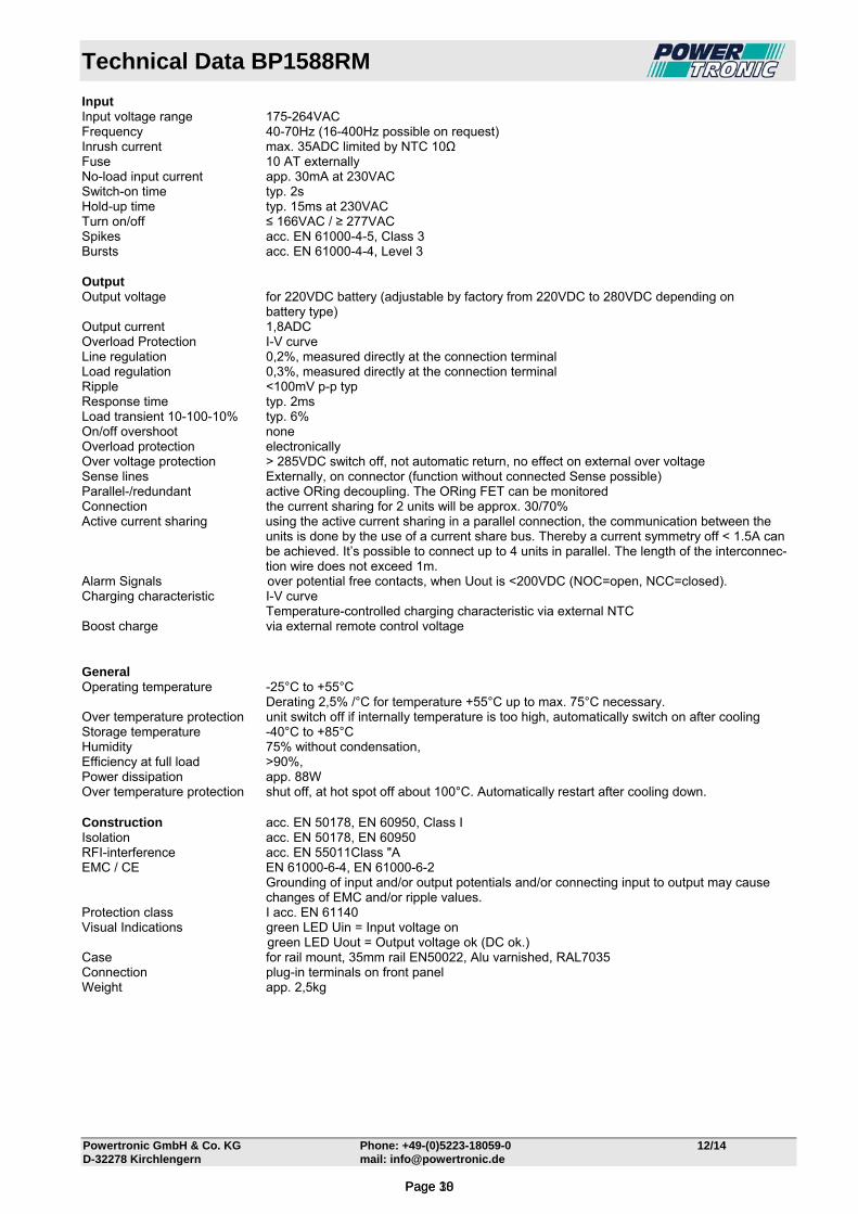
Technical Data BP1588RM
Powertronic GmbH & Co. KG Phone: +49-(0)5223-18059-0 12/14 D-32278 Kirchlengern mail: [email protected]
Input Input voltage range 175-264VAC Frequency 40-70Hz (16-400Hz possible on request) Inrush current max. 35ADC limited by NTC 10Ω Fuse 10 AT externally No-load input current app. 30mA at 230VAC Switch-on time typ. 2s Hold-up time typ. 15ms at 230VAC Turn on/off ≤ 166VAC / ≥ 277VAC Spikes acc. EN 61000-4-5, Class 3 Bursts acc. EN 61000-4-4, Level 3 Output Output voltage for 220VDC battery (adjustable by factory from 220VDC to 280VDC depending on battery type) Output current 1,8ADC Overload Protection I-V curve Line regulation 0,2%, measured directly at the connection terminal Load regulation 0,3%, measured directly at the connection terminal Ripple <100mV p-p typ Response time typ. 2ms Load transient 10-100-10% typ. 6% On/off overshoot none Overload protection electronically Over voltage protection > 285VDC switch off, not automatic return, no effect on external over voltage Sense lines Externally, on connector (function without connected Sense possible) Parallel-/redundant active ORing decoupling. The ORing FET can be monitored Connection the current sharing for 2 units will be approx. 30/70% Active current sharing using the active current sharing in a parallel connection, the communication between the
units is done by the use of a current share bus. Thereby a current symmetry off < 1.5A can be achieved. It’s possible to connect up to 4 units in parallel. The length of the interconnec-tion wire does not exceed 1m.
Alarm Signals over potential free contacts, when Uout is <200VDC (NOC=open, NCC=closed). Charging characteristic I-V curve Temperature-controlled charging characteristic via external NTC Boost charge via external remote control voltage General Operating temperature -25°C to +55°C Derating 2,5% /°C for temperature +55°C up to max. 75°C necessary. Over temperature protection unit switch off if internally temperature is too high, automatically switch on after cooling Storage temperature -40°C to +85°C Humidity 75% without condensation, Efficiency at full load ˃90%, Power dissipation app. 88W Over temperature protection shut off, at hot spot off about 100°C. Automatically restart after cooling down. Construction acc. EN 50178, EN 60950, Class I Isolation acc. EN 50178, EN 60950 RFI-interference acc. EN 55011Class "A EMC / CE EN 61000-6-4, EN 61000-6-2
Grounding of input and/or output potentials and/or connecting input to output may cause changes of EMC and/or ripple values.
Protection class I acc. EN 61140 Visual Indications green LED Uin = Input voltage on green LED Uout = Output voltage ok (DC ok.) Case for rail mount, 35mm rail EN50022, Alu varnished, RAL7035 Connection plug-in terminals on front panel Weight app. 2,5kg
Page 10Page 38
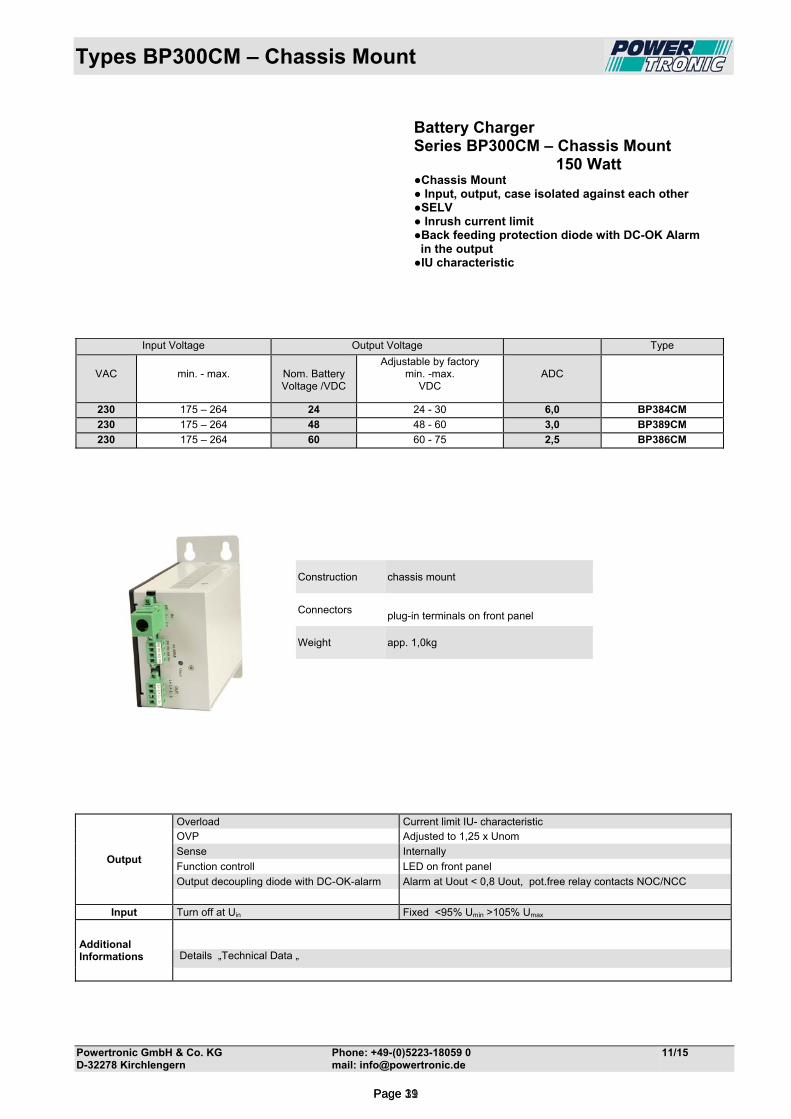
Types BP300CM – Chassis Mount
Powertronic GmbH & Co. KG Phone: +49-(0)5223-18059 0 11/15 D-32278 Kirchlengern mail: [email protected]
Battery Charger Series BP300CM – Chassis Mount 150 Watt Chassis Mount Input, output, case isolated against each other SELV Inrush current limit Back feeding protection diode with DC-OK Alarm in the output IU characteristic
Construction chassis mount
Connectors plug-in terminals on front panel
Weight app. 1,0kg
Output
Overload Current limit IU- characteristic OVP Adjusted to 1,25 x Unom
Sense Internally
Function controll LED on front panel
Output decoupling diode with DC-OK-alarm Alarm at Uout < 0,8 Uout, pot.free relay contacts NOC/NCC
Input Turn off at Uin Fixed <95% Umin >105% Umax
Additional Informations
Details „Technical Data „
Input Voltage Output Voltage Type
VAC
min. - max.
Nom. Battery Voltage /VDC
Adjustable by factory min. -max.
VDC
ADC
230 175 – 264 24 24 - 30 6,0 BP384CM
230 175 – 264 48 48 - 60 3,0 BP389CM
230 175 – 264 60 60 - 75 2,5 BP386CM
Page 11Page 39
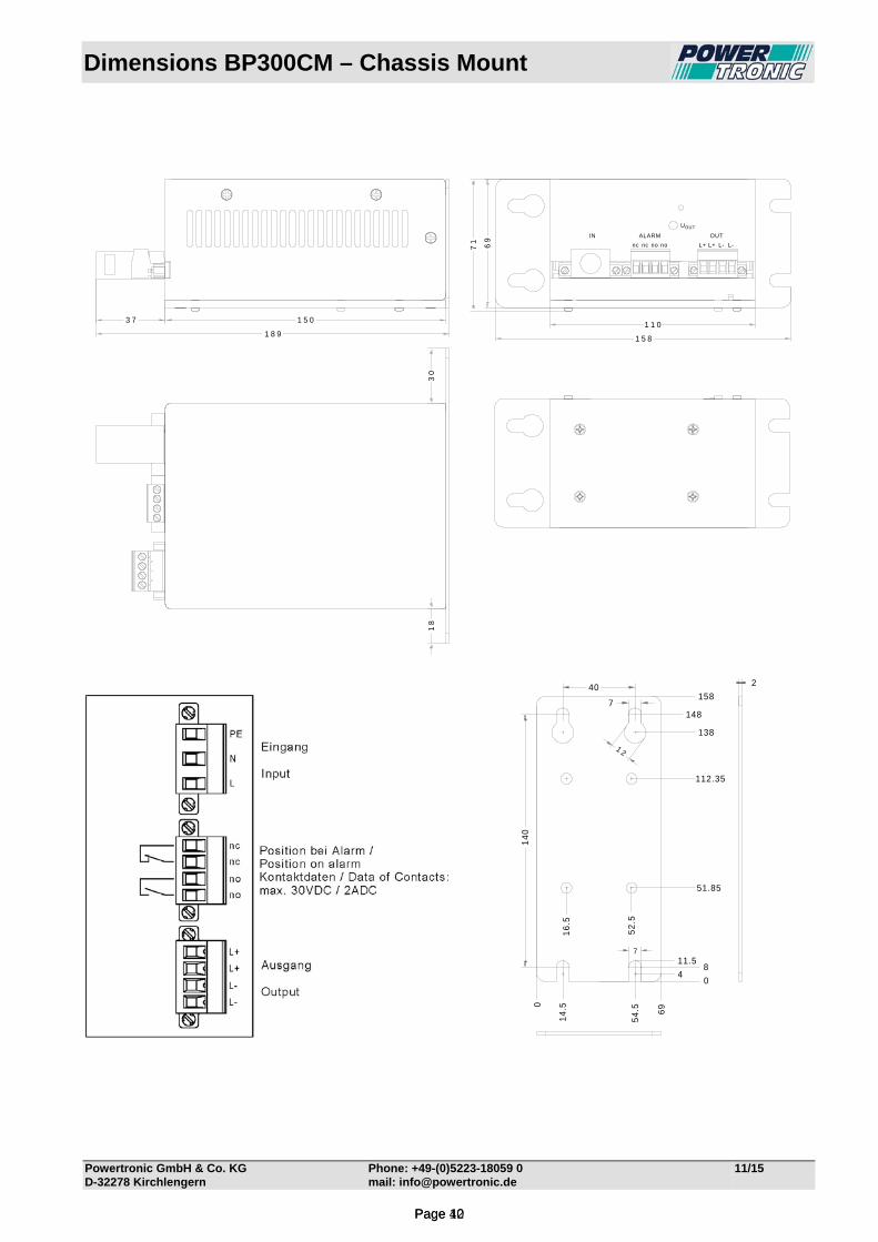
Dimensions BP300CM – Chassis Mount
Powertronic GmbH & Co. KG Phone: +49-(0)5223-18059 0 11/15 D-32278 Kirchlengern mail: [email protected]
nc nc no no L+ L+ L- L-
IN ALARM OUT
UOUT
1 1 01 5 03 7
69
71
1 5 8
30
18
1 8 9
2
7
14
0
40
7
0
54
.5
14
.5
52
.5
16
.5
0
158
138
112.35
51.85
4
148
8
69
1 2
11.5
Page 12Page 40

Technical Data BP384CM
Powertronic GmbH & Co. KG Phone: +49-(0)5223-18059-0 12/14 D-32278 Kirchlengern mail: [email protected]
Input Input voltage range 175-264VAC Frequency 40-70Hz (16-400Hz possible on request) Inrush current max. 35ADC limited by NTC 10Ω Fuse 2 AT externally No-load input current app. 20mA at 230VAC Switch-on time typ. 2s Hold-up time typ. 15ms at 230VAC Turn on/off ≤ 166VAC / ≥ 277VAC Spikes acc. EN 61000-4-5, Class 3 Bursts acc. EN 61000-4-4, Level 3 Output Output voltage for 24VDC battery (adjustable by factory from 24VDC to 30VDC depending on battery type) Output current 6ADC Overload Protection I-V curve Line regulation 0,2%, measured directly at the connection terminal Load regulation 0,3%, measured directly at the connection terminal Ripple <100mV p-p typ Response time typ. 2ms Load transient 10-100-10% typ. 6% On/off overshoot none Overload protection electronically Over voltage protection > 33 VDC switch off, not automatic return, no effect on external over voltage Back feeding protection diode in the output Alarm Signals over potential free contacts, when Uout is <20VDC (NOC=open, NCC=closed). Charging characteristic I-V curve Temperature-controlled charging characteristic via external NTC General Operating temperature -25°C to +55°C Derating 2,5% /°C for temperature +55°C up to max. 75°C necessary. Storage temperature -40°C to +85°C Humidity 75% without condensation, Efficiency at full load ˃90%, Power dissipation app. 25W Construction acc. EN 50178, EN 60950, Class I Isolation acc. EN 50178, EN 60950 SELV RFI-interference acc. EN 55011Class "A EMC / CE EN 61000-6-4, EN 61000-6-2
Grounding of input and/or output potentials and/or connecting input to output may cause changes of EMC and/or ripple values.
Protection class I acc. EN 61140 Visual Indications green LED Uout = Output voltage ok (DC ok.) Case for chassis mount, Alu varnished, RAL7035 Connection plug-in terminals on front panel Weight app. 1kg
Page 13Page 41

Technical Data BP389CM
Powertronic GmbH & Co. KG Phone: +49-(0)5223-18059-0 12/14 D-32278 Kirchlengern mail: [email protected]
Input Input voltage range 175-264VAC Frequency 40-70Hz (16-400Hz possible on request) Inrush current max. 35ADC limited by NTC 10Ω Fuse 2 AT externally No-load input current app. 20mA at 230VAC Switch-on time typ. 2s Hold-up time typ. 15ms at 230VAC Turn on/off ≤ 166VAC / ≥ 277VAC Spikes acc. EN 61000-4-5, Class 3 Bursts acc. EN 61000-4-4, Level 3 Output Output voltage for 48VDC battery (adjustable by factory from 48VDC to 60VDC depending on battery type) Output current 3ADC Overload Protection I-V curve Line regulation 0,2%, measured directly at the connection terminal Load regulation 0,3%, measured directly at the connection terminal Ripple <100mV p-p typ Response time typ. 2ms Load transient 10-100-10% typ. 6% On/off overshoot none Overload protection electronically Over voltage protection > 62VDC switch off, not automatic return, no effect on external over voltage Back feeding protection diode in the output Alarm Signals over potential free contacts, when Uout is <40VDC (NOC=open, NCC=closed). Charging characteristic I-V curve Temperature-controlled charging characteristic via external NTC General Operating temperature -25°C to +55°C Derating 2,5% /°C for temperature +55°C up to max. 75°C necessary. Storage temperature -40°C to +85°C Humidity 75% without condensation, Efficiency at full load ˃90%, Power dissipation app. 25W Construction acc. EN 50178, EN 60950, Class I Isolation acc. EN 50178, EN 60950 SELV RFI-interference acc. EN 55011Class "A EMC / CE EN 61000-6-4, EN 61000-6-2
Grounding of input and/or output potentials and/or connecting input to output may cause changes of EMC and/or ripple values.
Protection class I acc. EN 61140 Visual Indications green LED Uout = Output voltage ok (DC ok.) Case for chassis mount, Alu varnished, RAL7035 Connection plug-in terminals on front panel Weight app. 1kg
Page 14Page 42

Technical Data BP386CM
Powertronic GmbH & Co. KG Phone: +49-(0)5223-18059-0 12/14 D-32278 Kirchlengern mail: [email protected]
Input Input voltage range 175-264VAC Frequency 40-70Hz (16-400Hz possible on request) Inrush current max. 35ADC limited by NTC 10Ω Fuse 2 AT externally No-load input current app. 20mA at 230VAC Switch-on time typ. 2s Hold-up time typ. 15ms at 230VAC Turn on/off ≤ 166VAC / ≥ 277VAC Spikes acc. EN 61000-4-5, Class 3 Bursts acc. EN 61000-4-4, Level 3 Output Output voltage for 60VDC battery (adjustable by factory from 60VDC to 75VDC depending on battery type) Output current 2,5ADC Overload Protection I-V curve Line regulation 0,2%, measured directly at the connection terminal Load regulation 0,3%, measured directly at the connection terminal Ripple <100mV p-p typ Response time typ. 2ms Load transient 10-100-10% typ. 6% On/off overshoot none Overload protection electronically Over voltage protection > 78VDC switch off, not automatic return, no effect on external over voltage Back feeding protection diode in the output Alarm Signals over potential free contacts, when Uout is <50VDC (NOC=open, NCC=closed). Charging characteristic I-V curve Temperature-controlled charging characteristic via external NTC General Operating temperature -25°C to +55°C Derating 2,5% /°C for temperature +55°C up to max. 75°C necessary. Storage temperature -40°C to +85°C Humidity 75% without condensation, Efficiency at full load ˃90%, Power dissipation app. 25W Construction acc. EN 50178, EN 60950, Class I Isolation acc. EN 50178, EN 60950 SELV RFI-interference acc. EN 55011Class "A EMC / CE EN 61000-6-4, EN 61000-6-2
Grounding of input and/or output potentials and/or connecting input to output may cause changes of EMC and/or ripple values.
Protection class I acc. EN 61140 Visual Indications green LED Uout = Output voltage ok (DC ok.) Case for chassis mount, Alu varnished, RAL7035 Connection plug-in terminals on front panel Weight app. 1kg
Page 15Page 43
Types BP400CM – Chassis Mount
Powertronic GmbH & Co. KG Phone: +49-(0)5223-18059 0 11/15 D-32278 Kirchlengern mail: [email protected]
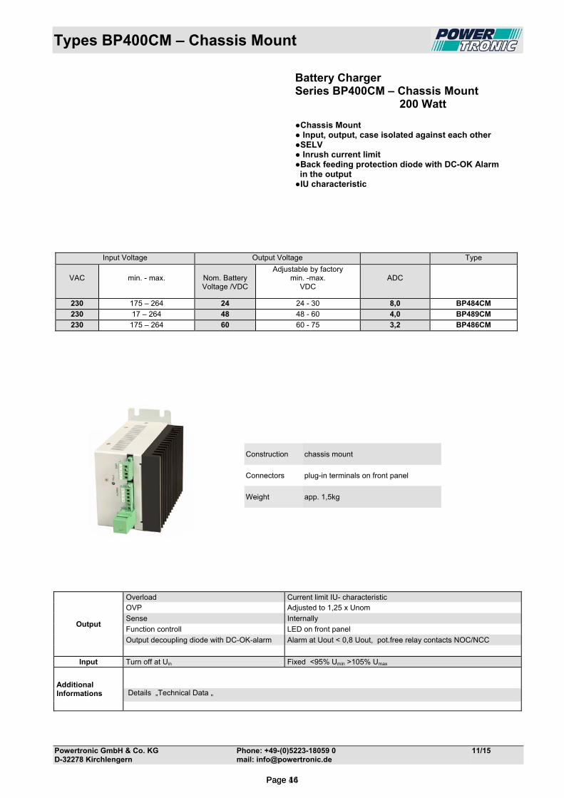
Battery Charger Series BP400CM – Chassis Mount 200 Watt Chassis Mount Input, output, case isolated against each other SELV Inrush current limit Back feeding protection diode with DC-OK Alarm in the output IU characteristic
Construction chassis mount
Connectors plug-in terminals on front panel
Weight app. 1,5kg
Output
Overload Current limit IU- characteristic OVP Adjusted to 1,25 x Unom
Sense Internally
Function controll LED on front panel
Output decoupling diode with DC-OK-alarm Alarm at Uout < 0,8 Uout, pot.free relay contacts NOC/NCC
Input Turn off at Uin Fixed <95% Umin >105% Umax
Additional Informations
Details „Technical Data „
Input Voltage Output Voltage Type
VAC
min. - max.
Nom. Battery Voltage /VDC
Adjustable by factory min. -max.
VDC
ADC
230 175 – 264 24 24 - 30 8,0 BP484CM
230 17 – 264 48 48 - 60 4,0 BP489CM
230 175 – 264 60 60 - 75 3,2 BP486CM
Page 16Page 44
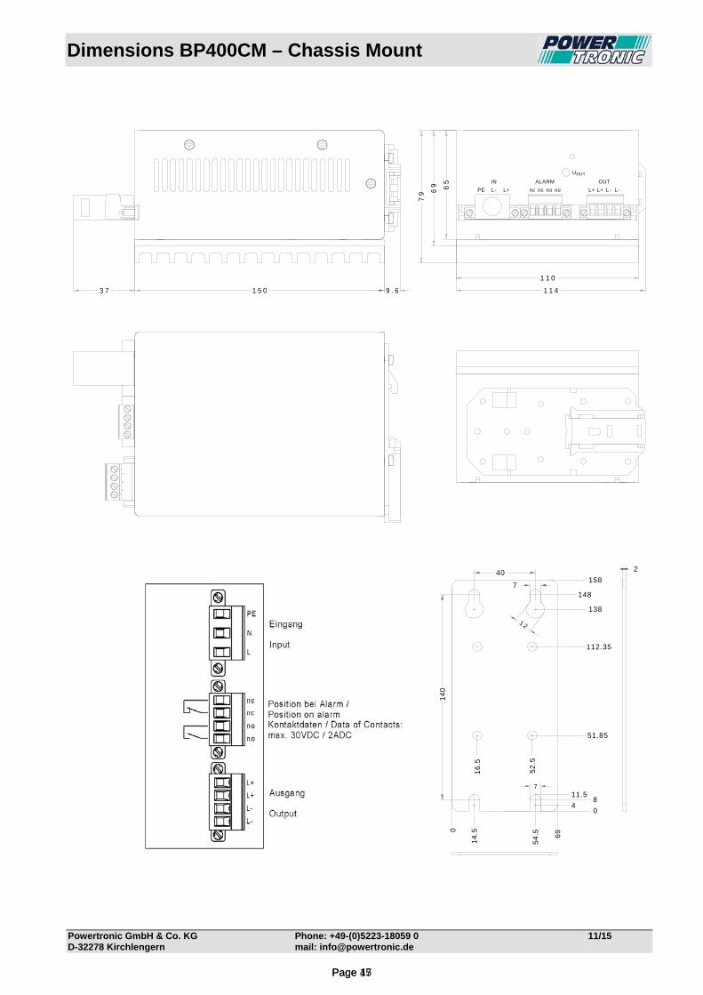
Dimensions BP400CM – Chassis Mount
Powertronic GmbH & Co. KG Phone: +49-(0)5223-18059 0 11/15 D-32278 Kirchlengern mail: [email protected]
PE L- L+ nc nc no no L+ L+ L- L-
IN ALARM OUT
UOUT
1 1 41 5 0 9 . 63 7
65
79
1 1 0
69
2
7
14
0
40
7
0
54
.5
14
.5
52
.5
16
.5
0
158
138
112.35
51.85
4
148
8
69
1 2
11.5
Page 17Page 45

Technical Data BP484CM
Powertronic GmbH & Co. KG Phone: +49-(0)5223-18059-0 12/14 D-32278 Kirchlengern mail: [email protected]
Input Input voltage range 175-264VAC Frequency 40-70Hz (16-400Hz possible on request) Inrush current max. 35ADC limited by NTC 10Ω Fuse 2 AT externally No-load input current app. 20mA at 230VAC Switch-on time typ. 2s Hold-up time typ. 15ms at 230VAC Turn on/off ≤ 166VAC / ≥ 277VAC Spikes acc. EN 61000-4-5, Class 3 Bursts acc. EN 61000-4-4, Level 3 Output Output voltage for 24VDC battery (adjustable by factory from 24VDC to 30VDC depending on battery type) Output current 8ADC Overload Protection I-V curve Line regulation 0,2%, measured directly at the connection terminal Load regulation 0,3%, measured directly at the connection terminal Ripple <100mV p-p typ Response time typ. 2ms Load transient 10-100-10% typ. 6% On/off overshoot none Overload protection electronically Over voltage protection > 33 VDC switch off, not automatic return, no effect on external over voltage Back feeding protection diode in the output Alarm Signals over potential free contacts, when Uout is <20VDC (NOC=open, NCC=closed). Charging characteristic I-V curve Temperature-controlled charging characteristic via external NTC General Operating temperature -25°C to +55°C Derating 2,5% /°C for temperature +55°C up to max. 75°C necessary. Storage temperature -40°C to +85°C Humidity 75% without condensation, Efficiency at full load ˃90%, Power dissipation app. 28W Construction acc. EN 50178, EN 60950, Class I Isolation acc. EN 50178, EN 60950 SELV RFI-interference acc. EN 55011Class "A EMC / CE EN 61000-6-4, EN 61000-6-2
Grounding of input and/or output potentials and/or connecting input to output may cause changes of EMC and/or ripple values.
Protection class I acc. EN 61140 Visual Indications green LED Uout = Output voltage ok (DC ok.) Case for chassis mount, Alu varnished RAL7035 Connection plug-in terminals on front panel Weight app. 1,5kg
Page 18Page 46

Technical Data BP489CM
Powertronic GmbH & Co. KG Phone: +49-(0)5223-18059-0 12/14 D-32278 Kirchlengern mail: [email protected]
Input Input voltage range 175-264VAC Frequency 40-70Hz (16-400Hz possible on request) Inrush current max. 35ADC limited by NTC 10Ω Fuse 2 AT externally No-load input current app. 20mA at 230VAC Switch-on time typ. 2s Hold-up time typ. 15ms at 230VAC Turn on/off ≤ 166VAC / ≥ 277VAC Spikes acc. EN 61000-4-5, Class 3 Bursts acc. EN 61000-4-4, Level 3 Output Output voltage for 48VDC battery (adjustable by factory from 48VDC to 60VDC depending on battery type) Output current 4ADC Overload Protection I-V curve Line regulation 0,2%, measured directly at the connection terminal Load regulation 0,3%, measured directly at the connection terminal Ripple <100mV p-p typ Response time typ. 2ms Load transient 10-100-10% typ. 6% On/off overshoot none Overload protection electronically Over voltage protection > 62VDC switch off, not automatic return, no effect on external over voltage Back feeding protection diode in the output Alarm Signals over potential free contacts, when Uout is <40VDC (NOC=open, NCC=closed). Charging characteristic I-V curve Temperature-controlled charging characteristic via external NTC General Operating temperature -25°C to +55°C Derating 2,5% /°C for temperature +55°C up to max. 75°C necessary. Storage temperature -40°C to +85°C Humidity 75% without condensation, Efficiency at full load ˃90%, Power dissipation app. 28W Construction acc. EN 50178, EN 60950, Class I Isolation acc. EN 50178, EN 60950 SELV RFI-interference acc. EN 55011Class "A EMC / CE EN 61000-6-4, EN 61000-6-2
Grounding of input and/or output potentials and/or connecting input to output may cause changes of EMC and/or ripple values.
Protection class I acc. EN 61140 Visual Indications green LED Uout = Output voltage ok (DC ok.) Case for chassis mount, Alu varnished, RAL7035 Connection plug-in terminals on front panel Weight app. 1,5kg
Page 19Page 47

Technical Data BP486CM
Powertronic GmbH & Co. KG Phone: +49-(0)5223-18059-0 12/14 D-32278 Kirchlengern mail: [email protected]
Input Input voltage range 175-264VAC Frequency 40-70Hz (16-400Hz possible on request) Inrush current max. 35ADC limited by NTC 10Ω Fuse 2 AT externally No-load input current app. 20mA at 230VAC Switch-on time typ. 2s Hold-up time typ. 15ms at 230VAC Turn on/off ≤ 166VAC / ≥ 277VAC Spikes acc. EN 61000-4-5, Class 3 Bursts acc. EN 61000-4-4, Level 3 Output Output voltage for 60VDC battery (adjustable by factory from 60VDC to 75VDC depending on battery type) Output current 3,2ADC Overload Protection I-V curve Line regulation 0,2%, measured directly at the connection terminal Load regulation 0,3%, measured directly at the connection terminal Ripple <100mV p-p typ Response time typ. 2ms Load transient 10-100-10% typ. 6% On/off overshoot none Overload protection electronically Over voltage protection > 78VDC switch off, not automatic return, no effect on external over voltage Back feeding protection diode in the output Alarm Signals over potential free contacts, when Uout is <50VDC (NOC=open, NCC=closed). Charging characteristic I-V curve Temperature-controlled charging characteristic via external NTC General Operating temperature -25°C to +55°C Derating 2,5% /°C for temperature +55°C up to max. 75°C necessary. Storage temperature -40°C to +85°C Humidity 75% without condensation, Efficiency at full load ˃90%, Power dissipation app. 28W Construction acc. EN 50178, EN 60950, Class I Isolation acc. EN 50178, EN 60950 SELV RFI-interference acc. EN 55011Class "A EMC / CE EN 61000-6-4, EN 61000-6-2
Grounding of input and/or output potentials and/or connecting input to output may cause changes of EMC and/or ripple values.
Protection class I acc. EN 61140 Visual Indications green LED Uout = Output voltage ok (DC ok.) Case for chassis mount, Alu varnished, RAL7035 Connection plug-in terminals on front panel Weight app. 1,5kg
Page 20Page 48
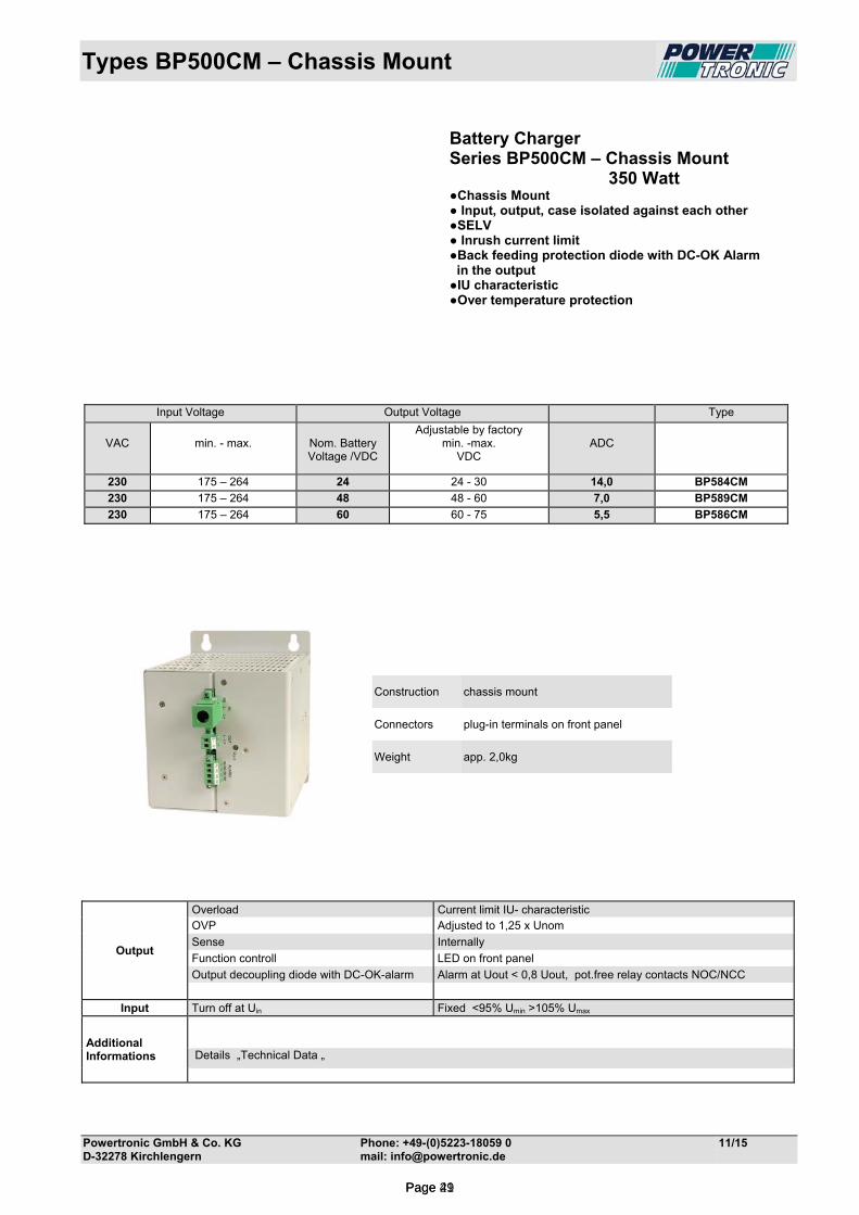
Types BP500CM – Chassis Mount
Powertronic GmbH & Co. KG Phone: +49-(0)5223-18059 0 11/15 D-32278 Kirchlengern mail: [email protected]
Battery Charger Series BP500CM – Chassis Mount 350 Watt Chassis Mount Input, output, case isolated against each other SELV Inrush current limit Back feeding protection diode with DC-OK Alarm in the output IU characteristic Over temperature protection
Construction chassis mount
Connectors plug-in terminals on front panel
Weight app. 2,0kg
Output
Overload Current limit IU- characteristic OVP Adjusted to 1,25 x Unom
Sense Internally
Function controll LED on front panel
Output decoupling diode with DC-OK-alarm Alarm at Uout < 0,8 Uout, pot.free relay contacts NOC/NCC
Input Turn off at Uin Fixed <95% Umin >105% Umax
Additional Informations
Details „Technical Data „
Input Voltage Output Voltage Type
VAC
min. - max.
Nom. Battery Voltage /VDC
Adjustable by factory min. -max.
VDC
ADC
230 175 – 264 24 24 - 30 14,0 BP584CM
230 175 – 264 48 48 - 60 7,0 BP589CM
230 175 – 264 60 60 - 75 5,5 BP586CM
Page 21Page 49
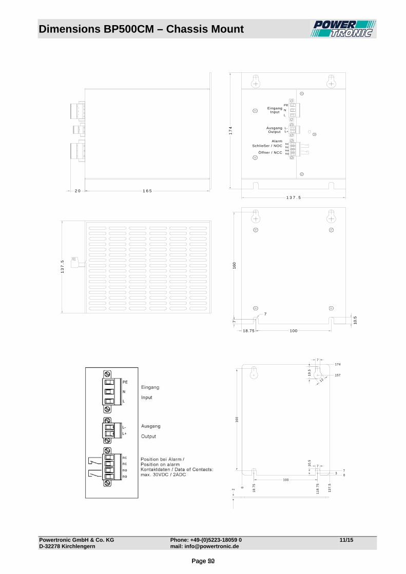
Dimensions BP500CM – Chassis Mount
Powertronic GmbH & Co. KG Phone: +49-(0)5223-18059 0 11/15 D-32278 Kirchlengern mail: [email protected]
21
60
100
7
7
0
18
.75
13
7.5
11
8.7
5
0
174
157
37
12
19
.51
0.5
nono
AusgangOutput
EingangInput
Schließer / NOC
Öffner / NCC
Alarm
ncnc
L+L-
L
N
PE
1 3 7 . 5
17
4
18.75 100
71
60
7
10
.5
13
7.5
1 6 52 0
Page 22Page 50
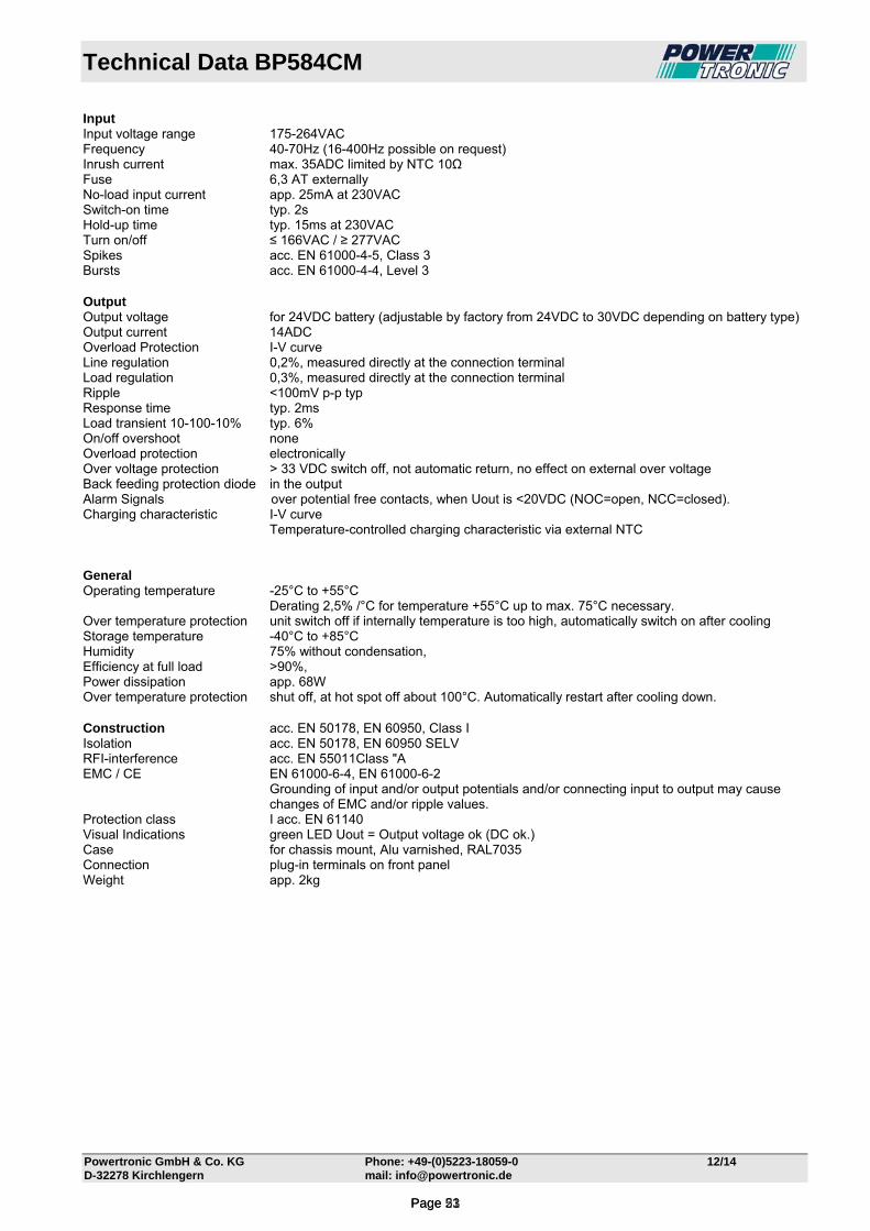
Technical Data BP584CM
Powertronic GmbH & Co. KG Phone: +49-(0)5223-18059-0 12/14 D-32278 Kirchlengern mail: [email protected]
Input Input voltage range 175-264VAC Frequency 40-70Hz (16-400Hz possible on request) Inrush current max. 35ADC limited by NTC 10Ω Fuse 6,3 AT externally No-load input current app. 25mA at 230VAC Switch-on time typ. 2s Hold-up time typ. 15ms at 230VAC Turn on/off ≤ 166VAC / ≥ 277VAC Spikes acc. EN 61000-4-5, Class 3 Bursts acc. EN 61000-4-4, Level 3 Output Output voltage for 24VDC battery (adjustable by factory from 24VDC to 30VDC depending on battery type) Output current 14ADC Overload Protection I-V curve Line regulation 0,2%, measured directly at the connection terminal Load regulation 0,3%, measured directly at the connection terminal Ripple <100mV p-p typ Response time typ. 2ms Load transient 10-100-10% typ. 6% On/off overshoot none Overload protection electronically Over voltage protection > 33 VDC switch off, not automatic return, no effect on external over voltage Back feeding protection diode in the output Alarm Signals over potential free contacts, when Uout is <20VDC (NOC=open, NCC=closed). Charging characteristic I-V curve Temperature-controlled charging characteristic via external NTC General Operating temperature -25°C to +55°C Derating 2,5% /°C for temperature +55°C up to max. 75°C necessary. Over temperature protection unit switch off if internally temperature is too high, automatically switch on after cooling Storage temperature -40°C to +85°C Humidity 75% without condensation, Efficiency at full load ˃90%, Power dissipation app. 68W Over temperature protection shut off, at hot spot off about 100°C. Automatically restart after cooling down. Construction acc. EN 50178, EN 60950, Class I Isolation acc. EN 50178, EN 60950 SELV RFI-interference acc. EN 55011Class "A EMC / CE EN 61000-6-4, EN 61000-6-2
Grounding of input and/or output potentials and/or connecting input to output may cause changes of EMC and/or ripple values.
Protection class I acc. EN 61140 Visual Indications green LED Uout = Output voltage ok (DC ok.) Case for chassis mount, Alu varnished, RAL7035 Connection plug-in terminals on front panel Weight app. 2kg
Page 23Page 51

Technical Data BP589CM
Powertronic GmbH & Co. KG Phone: +49-(0)5223-18059-0 12/14 D-32278 Kirchlengern mail: [email protected]
Input Input voltage range 175-264VAC Frequency 40-70Hz (16-400Hz possible on request) Inrush current max. 35ADC limited by NTC 10Ω Fuse 6,3 AT externally No-load input current app. 25mA at 230VAC Switch-on time typ. 2s Hold-up time typ. 15ms at 230VAC Turn on/off ≤ 166VAC / ≥ 277VAC Spikes acc. EN 61000-4-5, Class 3 Bursts acc. EN 61000-4-4, Level 3 Output Output voltage for 48VDC battery (adjustable by factory from 48VDC to 60VDC depending on battery type) Output current 7ADC Overload Protection I-V curve Line regulation 0,2%, measured directly at the connection terminal Load regulation 0,3%, measured directly at the connection terminal Ripple <100mV p-p typ Response time typ. 2ms Load transient 10-100-10% typ. 6% On/off overshoot none Overload protection electronically Over voltage protection > 62VDC switch off, not automatic return, no effect on external over voltage Back feeding protection diode in the output Alarm Signals over potential free contacts, when Uout is <40VDC (NOC=open, NCC=closed). Charging characteristic I-V curve Temperature-controlled charging characteristic via external NTC General Operating temperature -25°C to +55°C Derating 2,5% /°C for temperature +55°C up to max. 75°C necessary. Over temperature protection unit switch off if internally temperature is too high, automatically switch on after cooling Storage temperature -40°C to +85°C Humidity 75% without condensation, Efficiency at full load ˃90%, Power dissipation app. 68W Over temperature protection shut off, at hot spot off about 100°C. Automatically restart after cooling down. Construction acc. EN 50178, EN 60950, Class I Isolation acc. EN 50178, EN 60950 SELV RFI-interference acc. EN 55011Class "A EMC / CE EN 61000-6-4, EN 61000-6-2
Grounding of input and/or output potentials and/or connecting input to output may cause changes of EMC and/or ripple values.
Protection class I acc. EN 61140 Visual Indications green LED Uout = Output voltage ok (DC ok.) Case for chassis mount, Alu varnished, RAL7035 Connection plug-in terminals on front panel Weight app. 2kg
Page 24Page 52

Technical Data BP586CM
Powertronic GmbH & Co. KG Phone: +49-(0)5223-18059-0 12/14 D-32278 Kirchlengern mail: [email protected]
Input Input voltage range 175-264VAC Frequency 40-70Hz (16-400Hz possible on request) Inrush current max. 35ADC limited by NTC 10Ω Fuse 6,3 AT externally No-load input current app. 25mA at 230VAC Switch-on time typ. 2s Hold-up time typ. 15ms at 230VAC Turn on/off ≤ 166VAC / ≥ 277VAC Spikes acc. EN 61000-4-5, Class 3 Bursts acc. EN 61000-4-4, Level 3 Output Output voltage for 60VDC battery (adjustable by factory from 60VDC to 75VDC depending on battery type) Output current 5,5ADC Overload Protection I-V curve Line regulation 0,2%, measured directly at the connection terminal Load regulation 0,3%, measured directly at the connection terminal Ripple <100mV p-p typ Response time typ. 2ms Load transient 10-100-10% typ. 6% On/off overshoot none Overload protection electronically Over voltage protection > 78VDC switch off, not automatic return, no effect on external over voltage Back feeding protection diode in the output Alarm Signals over potential free contacts, when Uout is <50VDC (NOC=open, NCC=closed). Charging characteristic I-V curve Temperature-controlled charging characteristic via external NTC General Operating temperature -25°C to +55°C Derating 2,5% /°C for temperature +55°C up to max. 75°C necessary. Over temperature protection unit switch off if internally temperature is too high, automatically switch on after cooling Storage temperature -40°C to +85°C Humidity 75% without condensation, Efficiency at full load ˃90%, Power dissipation app. 68W Over temperature protection shut off, at hot spot off about 100°C. Automatically restart after cooling down. Construction acc. EN 50178, EN 60950, Class I Isolation acc. EN 50178, EN 60950 SELV RFI-interference acc. EN 55011Class "A EMC / CE EN 61000-6-4, EN 61000-6-2
Grounding of input and/or output potentials and/or connecting input to output may cause changes of EMC and/or ripple values.
Protection class I acc. EN 61140 Visual Indications green LED Uout = Output voltage ok (DC ok.) Case for chassis mount, Alu varnished, RAL7035 Connection plug-in terminals on front panel Weight app. 2kg
Page 25Page 53
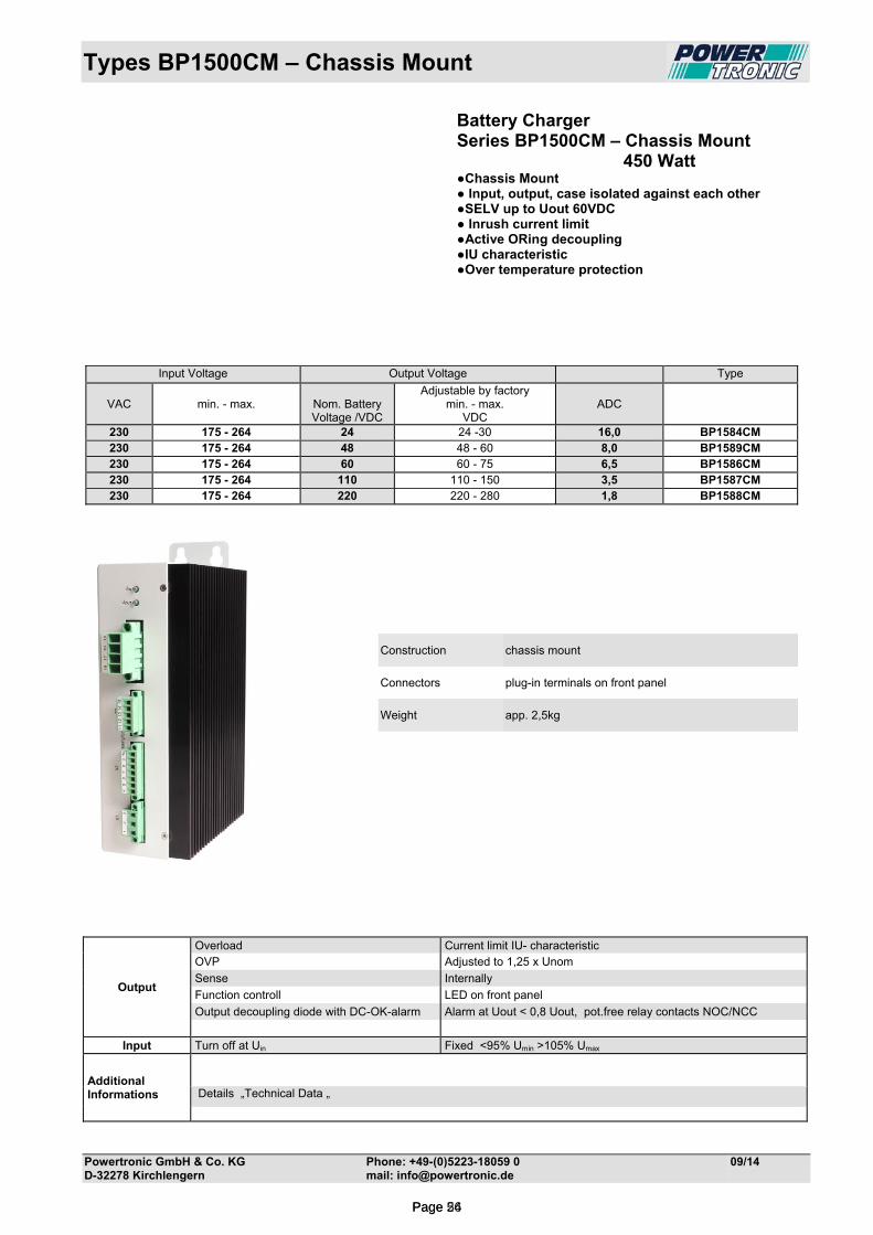
Types BP1500CM – Chassis Mount
Powertronic GmbH & Co. KG Phone: +49-(0)5223-18059 0 09/14 D-32278 Kirchlengern mail: [email protected]
Battery Charger Series BP1500CM – Chassis Mount 450 Watt Chassis Mount Input, output, case isolated against each other SELV up to Uout 60VDC Inrush current limit Active ORing decoupling IU characteristic Over temperature protection
Construction chassis mount
Connectors plug-in terminals on front panel
Weight app. 2,5kg
Output
Overload Current limit IU- characteristic OVP Adjusted to 1,25 x Unom
Sense Internally
Function controll LED on front panel
Output decoupling diode with DC-OK-alarm Alarm at Uout < 0,8 Uout, pot.free relay contacts NOC/NCC
Input Turn off at Uin Fixed <95% Umin >105% Umax
Additional Informations
Details „Technical Data „
Input Voltage Output Voltage Type
VAC
min. - max.
Nom. Battery Voltage /VDC
Adjustable by factory min. - max.
VDC
ADC
230 175 - 264 24 24 -30 16,0 BP1584CM 230 175 - 264 48 48 - 60 8,0 BP1589CM 230 175 - 264 60 60 - 75 6,5 BP1586CM 230 175 - 264 110 110 - 150 3,5 BP1587CM 230 175 - 264 220 220 - 280 1,8 BP1588CM
Page 26Page 54
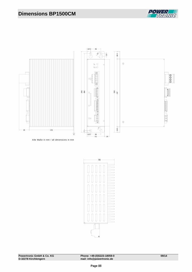
Dimensions BP1500CM
Powertronic GmbH & Co. KG Phone: +49-(0)5223-18059-0 09/14 D-32278 Kirchlengern mail: [email protected]
15535
61 182 3612.5
7
7
12.5 36
268
12
10
283
237283
19.5
26.5
A lle Maße in mm / all dim ensions in mm
79
Page 27Page 55
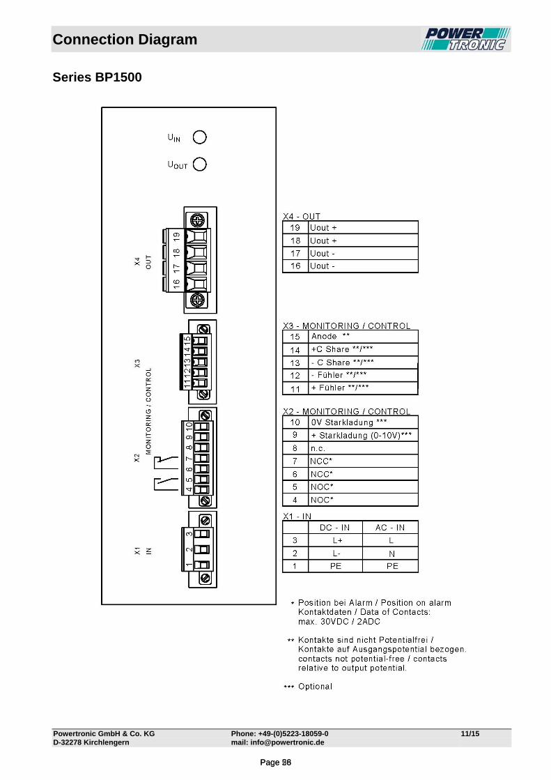
Connection Diagram
Powertronic GmbH & Co. KG Phone: +49-(0)5223-18059-0 11/15 D-32278 Kirchlengern mail: [email protected]
Series BP1500
Page 28Page 56

Technical Data BP1584CM
Powertronic GmbH & Co. KG Phone: +49-(0)5223-18059-0 12/14 D-32278 Kirchlengern mail: [email protected]
Input Input voltage range 175-264VAC Frequency 40-70Hz (16-400Hz possible on request) Inrush current max. 35ADC limited by NTC 10Ω Fuse 10 AT externally No-load input current app. 30mA at 230VAC Switch-on time typ. 2s Hold-up time typ. 15ms at 230VAC Turn on/off ≤ 166VAC / ≥ 277VAC Spikes acc. EN 61000-4-5, Class 3 Bursts acc. EN 61000-4-4, Level 3 Output Output voltage for 24VDC battery (adjustable by factory from 24VDC to 30VDC depending on battery type) Output current 14ADC Overload Protection I-V curve Line regulation 0,2%, measured directly at the connection terminal Load regulation 0,3%, measured directly at the connection terminal Ripple <100mV p-p typ Response time typ. 2ms Load transient 10-100-10% typ. 6% On/off overshoot none Overload protection electronically Over voltage protection > 33 VDC switch off, not automatic return, no effect on external over voltage Sense lines Externally, on connector (function without connected Sense possible) Parallel-/redundant active ORing decoupling. The ORing FET can be monitored Connection the current sharing for 2 units will be approx. 30/70% Active current sharing using the active current sharing in a parallel connection, the communication between the
units is done by the use of a current share bus. Thereby a current symmetry off < 1.5A can be achieved. It’s possible to connect up to 4 units in parallel. The length of the interconnec-tion wire does not exceed 1m.
Alarm Signals over potential free contacts, when Uout is <20VDC (NOC=open, NCC=closed). Charging characteristic I-V curve Temperature-controlled charging characteristic via external NTC Boost charge via external remote control voltage General Operating temperature -25°C to +55°C Derating 2,5% /°C for temperature +55°C up to max. 75°C necessary. Over temperature protection unit switch off if internally temperature is too high, automatically switch on after cooling Storage temperature -40°C to +85°C Humidity 75% without condensation, Efficiency at full load ˃90%, Power dissipation app. 88W Over temperature protection shut off, at hot spot off about 100°C. Automatically restart after cooling down. Construction acc. EN 50178, EN 60950, Class I Isolation acc. EN 50178, EN 60950 SELV RFI-interference acc. EN 55011Class "A EMC / CE EN 61000-6-4, EN 61000-6-2
Grounding of input and/or output potentials and/or connecting input to output may cause changes of EMC and/or ripple values.
Protection class I acc. EN 61140 Visual Indications green LED Uin = Input voltage on green LED Uout = Output voltage ok (DC ok.) Case for chassis mount, Alu varnished, RAL7035 Connection plug-in terminals on front panel Weight app. 2,5kg
Page 29Page 57

Technical Data BP1589CM
Powertronic GmbH & Co. KG Phone: +49-(0)5223-18059-0 12/14 D-32278 Kirchlengern mail: [email protected]
Input Input voltage range 175-264VAC Frequency 40-70Hz (16-400Hz possible on request) Inrush current max. 35ADC limited by NTC 10Ω Fuse 10 AT externally No-load input current app. 30mA at 230VAC Switch-on time typ. 2s Hold-up time typ. 15ms at 230VAC Turn on/off ≤ 166VAC / ≥ 277VAC Spikes acc. EN 61000-4-5, Class 3 Bursts acc. EN 61000-4-4, Level 3 Output Output voltage for 48VDC battery (adjustable by factory from 48VDC to 60VDC depending on battery type) Output current 8,0ADC Overload Protection I-V curve Line regulation 0,2%, measured directly at the connection terminal Load regulation 0,3%, measured directly at the connection terminal Ripple <100mV p-p typ Response time typ. 2ms Load transient 10-100-10% typ. 6% On/off overshoot none Overload protection electronically Over voltage protection > 62VDC switch off, not automatic return, no effect on external over voltage Sense lines Externally, on connector (function without connected Sense possible) Parallel-/redundant active ORing decoupling. The ORing FET can be monitored Connection the current sharing for 2 units will be approx. 30/70% Active current sharing using the active current sharing in a parallel connection, the communication between the
units is done by the use of a current share bus. Thereby a current symmetry off < 1.5A can be achieved. It’s possible to connect up to 4 units in parallel. The length of the interconnec-tion wire does not exceed 1m.
Alarm Signals over potential free contacts, when Uout is <40VDC (NOC=open, NCC=closed). Charging characteristic I-V curve Temperature-controlled charging characteristic via external NTC Boost charge via external remote control voltage General Operating temperature -25°C to +55°C Derating 2,5% /°C for temperature +55°C up to max. 75°C necessary. Over temperature protection unit switch off if internally temperature is too high, automatically switch on after cooling Storage temperature -40°C to +85°C Humidity 75% without condensation, Efficiency at full load ˃90%, Power dissipation app. 88W Over temperature protection shut off, at hot spot off about 100°C. Automatically restart after cooling down. Construction acc. EN 50178, EN 60950, Class I Isolation acc. EN 50178, EN 60950 SELV RFI-interference acc. EN 55011Class "A EMC / CE EN 61000-6-4, EN 61000-6-2
Grounding of input and/or output potentials and/or connecting input to output may cause changes of EMC and/or ripple values.
Protection class I acc. EN 61140 Visual Indications green LED Uin = Input voltage on green LED Uout = Output voltage ok (DC ok.) Case for chassis mount, Alu varnished, RAL7035 Connection plug-in terminals on front panel Weight app. 2,5kg
Page 30Page 58

Technical Data BP1586CM
Powertronic GmbH & Co. KG Phone: +49-(0)5223-18059-0 12/14 D-32278 Kirchlengern mail: [email protected]
Input Input voltage range 175-264VAC Frequency 40-70Hz (16-400Hz possible on request) Inrush current max. 35ADC limited by NTC 10Ω Fuse 10 AT externally No-load input current app. 30mA at 230VAC Switch-on time typ. 2s Hold-up time typ. 15ms at 230VAC Turn on/off ≤ 166VAC / ≥ 277VAC Spikes acc. EN 61000-4-5, Class 3 Bursts acc. EN 61000-4-4, Level 3 Output Output voltage for 60VDC battery (adjustable by factory from 60VDC to 75VDC depending on battery type) Output current 6,5ADC Overload Protection I-V curve Line regulation 0,2%, measured directly at the connection terminal Load regulation 0,3%, measured directly at the connection terminal Ripple <100mV p-p typ Response time typ. 2ms Load transient 10-100-10% typ. 6% On/off overshoot none Overload protection electronically Over voltage protection > 78VDC switch off, not automatic return, no effect on external over voltage Sense lines Externally, on connector (function without connected Sense possible) Parallel-/redundant active ORing decoupling. The ORing FET can be monitored Connection the current sharing for 2 units will be approx. 30/70% Active current sharing using the active current sharing in a parallel connection, the communication between the
units is done by the use of a current share bus. Thereby a current symmetry off < 1.5A can be achieved. It’s possible to connect up to 4 units in parallel. The length of the interconnec-tion wire does not exceed 1m.
Alarm Signals over potential free contacts, when Uout is <50VDC (NOC=open, NCC=closed). Charging characteristic I-V curve Temperature-controlled charging characteristic via external NTC Boost charge via external remote control voltage General Operating temperature -25°C to +55°C Derating 2,5% /°C for temperature +55°C up to max. 75°C necessary. Over temperature protection unit switch off if internally temperature is too high, automatically switch on after cooling Storage temperature -40°C to +85°C Humidity 75% without condensation, Efficiency at full load ˃90%, Power dissipation app. 88W Over temperature protection shut off, at hot spot off about 100°C. Automatically restart after cooling down. Construction acc. EN 50178, EN 60950, Class I Isolation acc. EN 50178, EN 60950 SELV RFI-interference acc. EN 55011Class "A EMC / CE EN 61000-6-4, EN 61000-6-2
Grounding of input and/or output potentials and/or connecting input to output may cause changes of EMC and/or ripple values.
Protection class I acc. EN 61140 Visual Indications green LED Uin = Input voltage on green LED Uout = Output voltage ok (DC ok.) Case for chassis mount, Alu varnished, RAL7035 Connection plug-in terminals on front panel Weight app. 2,5kg
Page 31Page 59
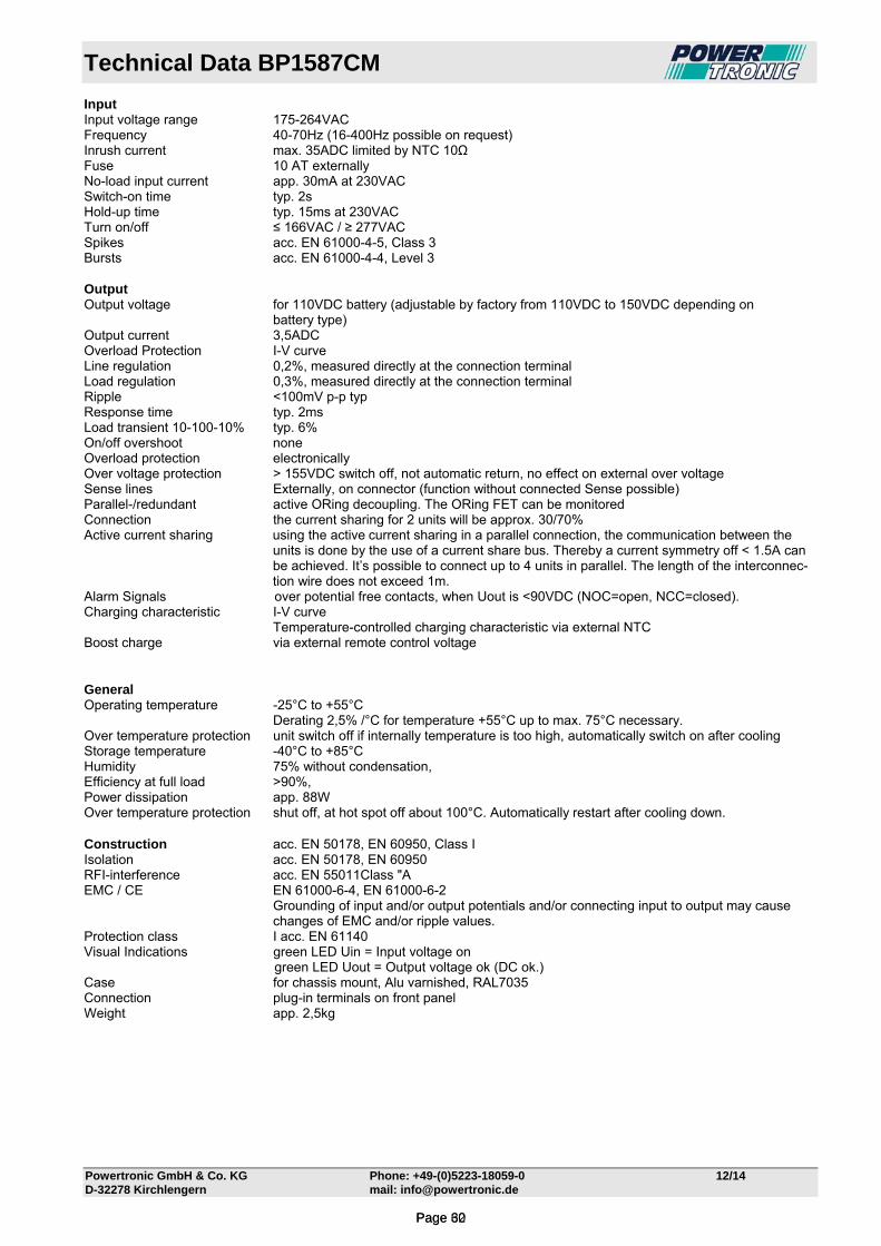
Technical Data BP1587CM
Powertronic GmbH & Co. KG Phone: +49-(0)5223-18059-0 12/14 D-32278 Kirchlengern mail: [email protected]
Input Input voltage range 175-264VAC Frequency 40-70Hz (16-400Hz possible on request) Inrush current max. 35ADC limited by NTC 10Ω Fuse 10 AT externally No-load input current app. 30mA at 230VAC Switch-on time typ. 2s Hold-up time typ. 15ms at 230VAC Turn on/off ≤ 166VAC / ≥ 277VAC Spikes acc. EN 61000-4-5, Class 3 Bursts acc. EN 61000-4-4, Level 3 Output Output voltage for 110VDC battery (adjustable by factory from 110VDC to 150VDC depending on battery type) Output current 3,5ADC Overload Protection I-V curve Line regulation 0,2%, measured directly at the connection terminal Load regulation 0,3%, measured directly at the connection terminal Ripple <100mV p-p typ Response time typ. 2ms Load transient 10-100-10% typ. 6% On/off overshoot none Overload protection electronically Over voltage protection > 155VDC switch off, not automatic return, no effect on external over voltage Sense lines Externally, on connector (function without connected Sense possible) Parallel-/redundant active ORing decoupling. The ORing FET can be monitored Connection the current sharing for 2 units will be approx. 30/70% Active current sharing using the active current sharing in a parallel connection, the communication between the
units is done by the use of a current share bus. Thereby a current symmetry off < 1.5A can be achieved. It’s possible to connect up to 4 units in parallel. The length of the interconnec-tion wire does not exceed 1m.
Alarm Signals over potential free contacts, when Uout is <90VDC (NOC=open, NCC=closed). Charging characteristic I-V curve Temperature-controlled charging characteristic via external NTC Boost charge via external remote control voltage General Operating temperature -25°C to +55°C Derating 2,5% /°C for temperature +55°C up to max. 75°C necessary. Over temperature protection unit switch off if internally temperature is too high, automatically switch on after cooling Storage temperature -40°C to +85°C Humidity 75% without condensation, Efficiency at full load ˃90%, Power dissipation app. 88W Over temperature protection shut off, at hot spot off about 100°C. Automatically restart after cooling down. Construction acc. EN 50178, EN 60950, Class I Isolation acc. EN 50178, EN 60950 RFI-interference acc. EN 55011Class "A EMC / CE EN 61000-6-4, EN 61000-6-2
Grounding of input and/or output potentials and/or connecting input to output may cause changes of EMC and/or ripple values.
Protection class I acc. EN 61140 Visual Indications green LED Uin = Input voltage on green LED Uout = Output voltage ok (DC ok.) Case for chassis mount, Alu varnished, RAL7035 Connection plug-in terminals on front panel Weight app. 2,5kg
Page 32Page 60

Technical Data BP1588CM
Powertronic GmbH & Co. KG Phone: +49-(0)5223-18059-0 12/14 D-32278 Kirchlengern mail: [email protected]
Input Input voltage range 175-264VAC Frequency 40-70Hz (16-400Hz possible on request) Inrush current max. 35ADC limited by NTC 10Ω Fuse 10 AT externally No-load input current app. 30mA at 230VAC Switch-on time typ. 2s Hold-up time typ. 15ms at 230VAC Turn on/off ≤ 166VAC / ≥ 277VAC Spikes acc. EN 61000-4-5, Class 3 Bursts acc. EN 61000-4-4, Level 3 Output Output voltage for 220VDC battery (adjustable by factory from 220VDC to 280VDC depending on battery type) Output current 1,8ADC Overload Protection I-V curve Line regulation 0,2%, measured directly at the connection terminal Load regulation 0,3%, measured directly at the connection terminal Ripple <100mV p-p typ Response time typ. 2ms Load transient 10-100-10% typ. 6% On/off overshoot none Overload protection electronically Over voltage protection > 285VDC switch off, not automatic return, no effect on external over voltage Sense lines Externally, on connector (function without connected Sense possible) Parallel-/redundant active ORing decoupling. The ORing FET can be monitored Connection the current sharing for 2 units will be approx. 30/70% Active current sharing using the active current sharing in a parallel connection, the communication between the
units is done by the use of a current share bus. Thereby a current symmetry off < 1.5A can be achieved. It’s possible to connect up to 4 units in parallel. The length of the interconnec-tion wire does not exceed 1m.
Alarm Signals over potential free contacts, when Uout is <200VDC (NOC=open, NCC=closed). Charging characteristic I-V curve Temperature-controlled charging characteristic via external NTC Boost charge via external remote control voltage General Operating temperature -25°C to +55°C Derating 2,5% /°C for temperature +55°C up to max. 75°C necessary. Over temperature protection unit switch off if internally temperature is too high, automatically switch on after cooling Storage temperature -40°C to +85°C Humidity 75% without condensation, Efficiency at full load ˃90%, Power dissipation app. 88W Over temperature protection shut off, at hot spot off about 100°C. Automatically restart after cooling down. Construction acc. EN 50178, EN 60950, Class I Isolation acc. EN 50178, EN 60950 RFI-interference acc. EN 55011Class "A EMC / CE EN 61000-6-4, EN 61000-6-2
Grounding of input and/or output potentials and/or connecting input to output may cause changes of EMC and/or ripple values.
Protection class I acc. EN 61140 Visual Indications green LED Uin = Input voltage on green LED Uout = Output voltage ok (DC ok.) Case for chassis mount, Alu varnished, RAL7035 Connection plug-in terminals on front panel Weight app. 2,5kg
Page 33Page 61
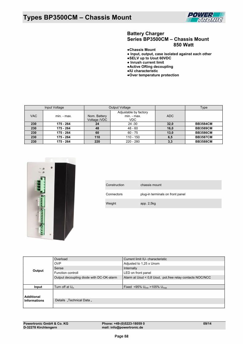
Types BP3500CM – Chassis Mount
Powertronic GmbH & Co. KG Phone: +49-(0)5223-18059 0 09/14 D-32278 Kirchlengern mail: [email protected]
Battery Charger Series BP3500CM – Chassis Mount 850 Watt Chassis Mount Input, output, case isolated against each other SELV up to Uout 60VDC Inrush current limit Active ORing decoupling IU characteristic Over temperature protection
Construction chassis mount
Connectors plug-in terminals on front panel
Weight app. 2,5kg
Output
Overload Current limit IU- characteristic OVP Adjusted to 1,25 x Unom
Sense Internally
Function controll LED on front panel
Output decoupling diode with DC-OK-alarm Alarm at Uout < 0,8 Uout, pot.free relay contacts NOC/NCC
Input Turn off at Uin Fixed <95% Umin >105% Umax
Additional Informations
Details „Technical Data „
Input Voltage Output Voltage Type
VAC
min. - max.
Nom. Battery Voltage /VDC
Adjustable by factory min. - max.
VDC
ADC
230 175 - 264 24 24 -30 32,0 BB3584CM 230 175 - 264 48 48 - 60 16,0 BB3589CM 230 175 - 264 60 60 - 75 13,0 BB3586CM 230 175 - 264 110 110 - 150 6,5 BB3587CM 230 175 - 264 220 220 - 280 3,3 BB3588CM
Page 34Page 62
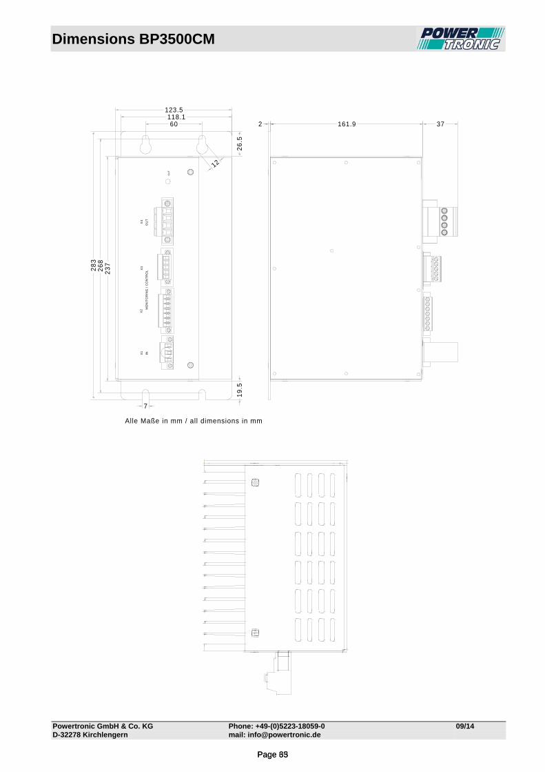
Dimensions BP3500CM
Powertronic GmbH & Co. KG Phone: +49-(0)5223-18059-0 09/14 D-32278 Kirchlengern mail: [email protected]
60118.1
123.5
161.9 372
23
72
68
28
3
OU
T
7
12
19
.52
6.5
X2
X1
X3
X4
MO
NIT
OR
ING
/C
ON
TR
OL
INO
UT
Alle Maße in mm / all dimensions in mm
Page 35Page 63
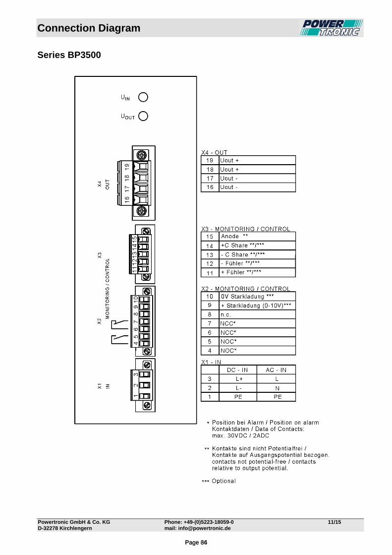
Connection Diagram
Powertronic GmbH & Co. KG Phone: +49-(0)5223-18059-0 11/15 D-32278 Kirchlengern mail: [email protected]
Series BP3500
Page 36Page 64
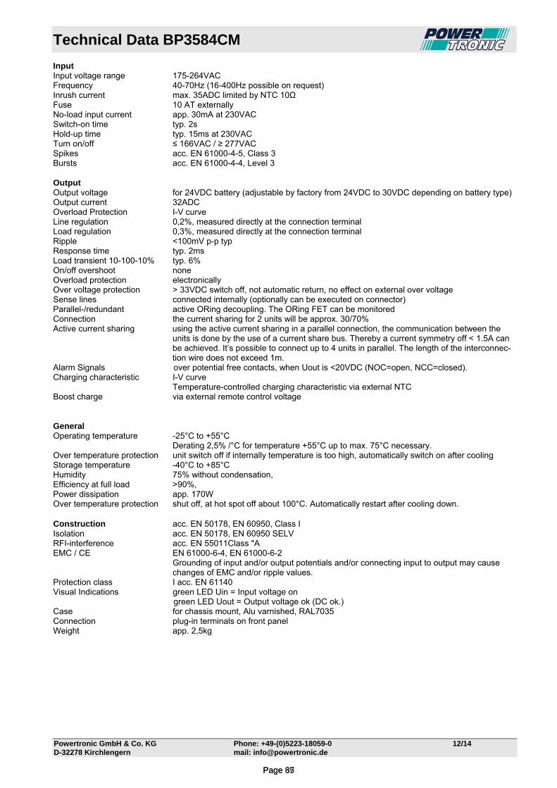
Technical Data BP3584CM
Powertronic GmbH & Co. KG Phone: +49-(0)5223-18059-0 12/14 D-32278 Kirchlengern mail: [email protected]
Input Input voltage range 175-264VAC Frequency 40-70Hz (16-400Hz possible on request) Inrush current max. 35ADC limited by NTC 10Ω Fuse 10 AT externally No-load input current app. 30mA at 230VAC Switch-on time typ. 2s Hold-up time typ. 15ms at 230VAC Turn on/off ≤ 166VAC / ≥ 277VAC Spikes acc. EN 61000-4-5, Class 3 Bursts acc. EN 61000-4-4, Level 3 Output Output voltage for 24VDC battery (adjustable by factory from 24VDC to 30VDC depending on battery type) Output current 32ADC Overload Protection I-V curve Line regulation 0,2%, measured directly at the connection terminal Load regulation 0,3%, measured directly at the connection terminal Ripple <100mV p-p typ Response time typ. 2ms Load transient 10-100-10% typ. 6% On/off overshoot none Overload protection electronically Over voltage protection > 33VDC switch off, not automatic return, no effect on external over voltage Sense lines connected internally (optionally can be executed on connector) Parallel-/redundant active ORing decoupling. The ORing FET can be monitored Connection the current sharing for 2 units will be approx. 30/70% Active current sharing using the active current sharing in a parallel connection, the communication between the
units is done by the use of a current share bus. Thereby a current symmetry off < 1.5A can be achieved. It’s possible to connect up to 4 units in parallel. The length of the interconnec-tion wire does not exceed 1m.
Alarm Signals over potential free contacts, when Uout is <20VDC (NOC=open, NCC=closed). Charging characteristic I-V curve Temperature-controlled charging characteristic via external NTC Boost charge via external remote control voltage General Operating temperature -25°C to +55°C Derating 2,5% /°C for temperature +55°C up to max. 75°C necessary. Over temperature protection unit switch off if internally temperature is too high, automatically switch on after cooling Storage temperature -40°C to +85°C Humidity 75% without condensation, Efficiency at full load ˃90%, Power dissipation app. 170W Over temperature protection shut off, at hot spot off about 100°C. Automatically restart after cooling down. Construction acc. EN 50178, EN 60950, Class I Isolation acc. EN 50178, EN 60950 SELV RFI-interference acc. EN 55011Class "A EMC / CE EN 61000-6-4, EN 61000-6-2
Grounding of input and/or output potentials and/or connecting input to output may cause changes of EMC and/or ripple values.
Protection class I acc. EN 61140 Visual Indications green LED Uin = Input voltage on green LED Uout = Output voltage ok (DC ok.) Case for chassis mount, Alu varnished, RAL7035 Connection plug-in terminals on front panel Weight app. 2,5kg
Page 37Page 65

Technical Data BP3589CM
Powertronic GmbH & Co. KG Phone: +49-(0)5223-18059-0 12/14 D-32278 Kirchlengern mail: [email protected]
Input Input voltage range 175-264VAC Frequency 40-70Hz (16-400Hz possible on request) Inrush current max. 35ADC limited by NTC 10Ω Fuse 10 AT externally No-load input current app. 30mA at 230VAC Switch-on time typ. 2s Hold-up time typ. 15ms at 230VAC Turn on/off ≤ 166VAC / ≥ 277VAC Spikes acc. EN 61000-4-5, Class 3 Bursts acc. EN 61000-4-4, Level 3 Output Output voltage for 48VDC battery (adjustable by factory from 48VDC to 60VDC depending on battery type) Output current 16ADC Overload Protection I-V curve Line regulation 0,2%, measured directly at the connection terminal Load regulation 0,3%, measured directly at the connection terminal Ripple <100mV p-p typ Response time typ. 2ms Load transient 10-100-10% typ. 6% On/off overshoot none Overload protection electronically Over voltage protection > 63VDC switch off, not automatic return, no effect on external over voltage Sense lines Externally, on connector (function without connected Sense possible) Parallel-/redundant active ORing decoupling. The ORing FET can be monitored Connection the current sharing for 2 units will be approx. 30/70% Active current sharing using the active current sharing in a parallel connection, the communication between the
units is done by the use of a current share bus. Thereby a current symmetry off < 1.5A can be achieved. It’s possible to connect up to 4 units in parallel. The length of the interconnec-tion wire does not exceed 1m.
Alarm Signals over potential free contacts, when Uout is <40VDC (NOC=open, NCC=closed). Charging characteristic I-V curve Temperature-controlled charging characteristic via external NTC Boost charge via external remote control voltage General Operating temperature -25°C to +55°C Derating 2,5% /°C for temperature +55°C up to max. 75°C necessary. Over temperature protection unit switch off if internally temperature is too high, automatically switch on after cooling Storage temperature -40°C to +85°C Humidity 75% without condensation, Efficiency at full load ˃90%, Power dissipation app. 170W Over temperature protection shut off, at hot spot off about 100°C. Automatically restart after cooling down. Construction acc. EN 50178, EN 60950, Class I Isolation acc. EN 50178, EN 60950 SELV RFI-interference acc. EN 55011Class "A EMC / CE EN 61000-6-4, EN 61000-6-2
Grounding of input and/or output potentials and/or connecting input to output may cause changes of EMC and/or ripple values.
Protection class I acc. EN 61140 Visual Indications green LED Uin = Input voltage on green LED Uout = Output voltage ok (DC ok.) Case for chassis mount, Alu varnished, RAL7035 Connection plug-in terminals on front panel Weight app. 2,5kg
Page 38Page 66
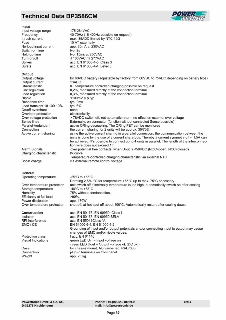
Technical Data BP3586CM
Powertronic GmbH & Co. KG Phone: +49-(0)5223-18059-0 12/14 D-32278 Kirchlengern mail: [email protected]
Input Input voltage range 175-264VAC Frequency 40-70Hz (16-400Hz possible on request) Inrush current max. 35ADC limited by NTC 10Ω Fuse 10 AT externally No-load input current app. 30mA at 230VAC Switch-on time typ. 2s Hold-up time typ. 15ms at 230VAC Turn on/off ≤ 166VAC / ≥ 277VAC Spikes acc. EN 61000-4-5, Class 3 Bursts acc. EN 61000-4-4, Level 3 Output Output voltage for 60VDC battery (adjustable by factory from 60VDC to 75VDC depending on battery type) Output current 13ADC Characteristic IU, temperature controlled charging possible on request Line regulation 0,2%, measured directly at the connection terminal Load regulation 0,3%, measured directly at the connection terminal Ripple <100mV p-p typ Response time typ. 2ms Load transient 10-100-10% typ. 6% On/off overshoot none Overload protection electronically Over voltage protection > 78VDC switch off, not automatic return, no effect on external over voltage Sense lines Externally, on connector (function without connected Sense possible) Parallel-/redundant active ORing decoupling. The ORing FET can be monitored Connection the current sharing for 2 units will be approx. 30/70% Active current sharing using the active current sharing in a parallel connection, the communication between the
units is done by the use of a current share bus. Thereby a current symmetry off < 1.5A can be achieved. It’s possible to connect up to 4 units in parallel. The length of the interconnec-tion wire does not exceed 1m.
Alarm Signals over potential free contacts, when Uout is <50VDC (NOC=open, NCC=closed). Charging characteristic IV curve Temperature-controlled charging characteristic via external NTC Boost charge via external remote control voltage General Operating temperature -25°C to +55°C Derating 2,5% /°C for temperature +55°C up to max. 75°C necessary. Over temperature protection unit switch off if internally temperature is too high, automatically switch on after cooling Storage temperature -40°C to +85°C Humidity 75% without condensation, Efficiency at full load ˃90%, Power dissipation app. 170W Over temperature protection shut off, at hot spot off about 100°C. Automatically restart after cooling down. Construction acc. EN 50178, EN 60950, Class I Isolation acc. EN 50178, EN 60950 SELV RFI-interference acc. EN 55011Class "A EMC / CE EN 61000-6-4, EN 61000-6-2
Grounding of input and/or output potentials and/or connecting input to output may cause changes of EMC and/or ripple values.
Protection class I acc. EN 61140 Visual Indications green LED Uin = Input voltage on green LED Uout = Output voltage ok (DC ok.) Case for chassis mount, Alu varnished, RAL7035 Connection plug-in terminals on front panel Weight app. 2,5kg
Page 39Page 67

Technical Data BP3587CM
Powertronic GmbH & Co. KG Phone: +49-(0)5223-18059-0 12/14 D-32278 Kirchlengern mail: [email protected]
Input Input voltage range 175-264VAC Frequency 40-70Hz (16-400Hz possible on request) Inrush current max. 35ADC limited by NTC 10Ω Fuse 10 AT externally No-load input current app. 30mA at 230VAC Switch-on time typ. 2s Hold-up time typ. 15ms at 230VAC Turn on/off ≤ 166VAC / ≥ 277VAC Spikes acc. EN 61000-4-5, Class 3 Bursts acc. EN 61000-4-4, Level 3 Output Output voltage for 110VDC battery (adjustable by factory from 110VDC to 150VDC depending on battery type) Output current 6,5ADC Overload Protection I-V curve Line regulation 0,2%, measured directly at the connection terminal Load regulation 0,3%, measured directly at the connection terminal Ripple <100mV p-p typ Response time typ. 2ms Load transient 10-100-10% typ. 6% On/off overshoot none Overload protection electronically Over voltage protection > 155VDC switch off, not automatic return, no effect on external over voltage Sense lines Externally, on connector (function without connected Sense possible) Parallel-/redundant active ORing decoupling. The ORing FET can be monitored Connection the current sharing for 2 units will be approx. 30/70% Active current sharing using the active current sharing in a parallel connection, the communication between the
units is done by the use of a current share bus. Thereby a current symmetry off < 1.5A can be achieved. It’s possible to connect up to 4 units in parallel. The length of the interconnec-tion wire does not exceed 1m.
Alarm Signals over potential free contacts, when Uout is <90VDC (NOC=open, NCC=closed). Charging characteristic I-V curve Temperature-controlled charging characteristic via external NTC Boost charge via external remote control voltage General Operating temperature -25°C to +55°C Derating 2,5% /°C for temperature +55°C up to max. 75°C necessary. Over temperature protection unit switch off if internally temperature is too high, automatically switch on after cooling Storage temperature -40°C to +85°C Humidity 75% without condensation, Efficiency at full load ˃90%, Power dissipation app. 170W Over temperature protection shut off, at hot spot off about 100°C. Automatically restart after cooling down. Construction acc. EN 50178, EN 60950, Class I Isolation acc. EN 50178, EN 60950 RFI-interference acc. EN 55011Class "A EMC / CE EN 61000-6-4, EN 61000-6-2
Grounding of input and/or output potentials and/or connecting input to output may cause changes of EMC and/or ripple values.
Protection class I acc. EN 61140 Visual Indications green LED Uin = Input voltage on green LED Uout = Output voltage ok (DC ok.) Case for chassis mount, Alu varnished, RAL7035 Connection plug-in terminals on front panel Weight app. 2,5kg
Page 40Page 68

Technical Data BP3588CM
Powertronic GmbH & Co. KG Phone: +49-(0)5223-18059-0 12/14 D-32278 Kirchlengern mail: [email protected]
Input Input voltage range 175-264VAC Frequency 40-70Hz (16-400Hz possible on request) Inrush current max. 35ADC limited by NTC 10Ω Fuse 10 AT externally No-load input current app. 30mA at 230VAC Switch-on time typ. 2s Hold-up time typ. 15ms at 230VAC Turn on/off ≤ 166VAC / ≥ 277VAC Spikes acc. EN 61000-4-5, Class 3 Bursts acc. EN 61000-4-4, Level 3 Output Output voltage for 220VDC battery (adjustable by factory from 220VDC to 280VDC depending on battery type) Output current 3,3ADC Overload Protection I-V curve Line regulation 0,2%, measured directly at the connection terminal Load regulation 0,3%, measured directly at the connection terminal Ripple <100mV p-p typ Response time typ. 2ms Load transient 10-100-10% typ. 6% On/off overshoot none Overload protection electronically Over voltage protection > 285VDC switch off, not automatic return, no effect on external over voltage Sense lines Externally, on connector (function without connected Sense possible) Parallel-/redundant active ORing decoupling. The ORing FET can be monitored Connection the current sharing for 2 units will be approx. 30/70% Active current sharing using the active current sharing in a parallel connection, the communication between the
units is done by the use of a current share bus. Thereby a current symmetry off < 1.5A can be achieved. It’s possible to connect up to 4 units in parallel. The length of the interconnec-tion wire does not exceed 1m.
Alarm Signals over potential free contacts, when Uout is <200VDC (NOC=open, NCC=closed). Charging characteristic I-V curve Temperature-controlled charging characteristic via external NTC Boost charge via external remote control voltage General Operating temperature -25°C to +55°C Derating 2,5% /°C for temperature +55°C up to max. 75°C necessary. Over temperature protection unit switch off if internally temperature is too high, automatically switch on after cooling Storage temperature -40°C to +85°C Humidity 75% without condensation, Efficiency at full load ˃90%, Power dissipation app. 170W Over temperature protection shut off, at hot spot off about 100°C. Automatically restart after cooling down. Construction acc. EN 50178, EN 60950, Class I Isolation acc. EN 50178, EN 60950 RFI-interference acc. EN 55011Class "A EMC / CE EN 61000-6-4, EN 61000-6-2
Grounding of input and/or output potentials and/or connecting input to output may cause changes of EMC and/or ripple values.
Protection class I acc. EN 61140 Visual Indications green LED Uin = Input voltage on green LED Uout = Output voltage ok (DC ok.) Case for chassis mount, Alu varnished, RAL7035 Connection plug-in terminals on front panel Weight app. 2,5kg
Page 41Page 69
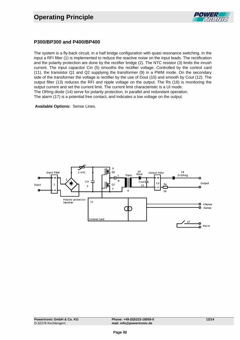
Operating Principle
Powertronic GmbH & Co. KG Phone: +49-(0)5223-18059-0 12/14 D-32278 Kirchlengern mail: [email protected]
P300/BP300 and P400/BP400 The system is a fly-back circuit, in a half bridge configuration with quasi resonance switching. In the input a RFI filter (1) is implemented to reduce the reactive noise on the input leads. The rectification and the polarity protection are done by the rectifier bridge (2). The NTC resistor (3) limits the inrush current. The input capacitor Cin (5) smooths the rectifier voltage. Controlled by the control card (11), the transistor Q1 and Q2 supplying the transformer (9) in a PWM mode. On the secondary side of the transformer the voltage is rectifier by the use of Dout (10) and smooth by Cout (12). The output filter (13) reduces the RFI and ripple voltage on the output. The Rs (16) is monitoring the output current and set the current limit. The current limit characteristic is a UI mode. The ORing diode (14) serve for polarity protection, in parallel and redundant operation. The alarm (17) is a potential free contact, and indicates a low voltage on the output. Available Options: Sense Lines.
Page 42Page 70
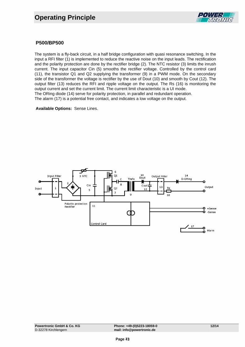
Operating Principle
Powertronic GmbH & Co. KG Phone: +49-(0)5223-18059-0 12/14 D-32278 Kirchlengern mail: [email protected]
P500/BP500 The system is a fly-back circuit, in a half bridge configuration with quasi resonance switching. In the input a RFI filter (1) is implemented to reduce the reactive noise on the input leads. The rectification and the polarity protection are done by the rectifier bridge (2). The NTC resistor (3) limits the inrush current. The input capacitor Cin (5) smooths the rectifier voltage. Controlled by the control card (11), the transistor Q1 and Q2 supplying the transformer (9) in a PWM mode. On the secondary side of the transformer the voltage is rectifier by the use of Dout (10) and smooth by Cout (12). The output filter (13) reduces the RFI and ripple voltage on the output. The Rs (16) is monitoring the output current and set the current limit. The current limit characteristic is a UI mode. The ORing diode (14) serve for polarity protection, in parallel and redundant operation. The alarm (17) is a potential free contact, and indicates a low voltage on the output. Available Options: Sense Lines.
Page 43Page 71
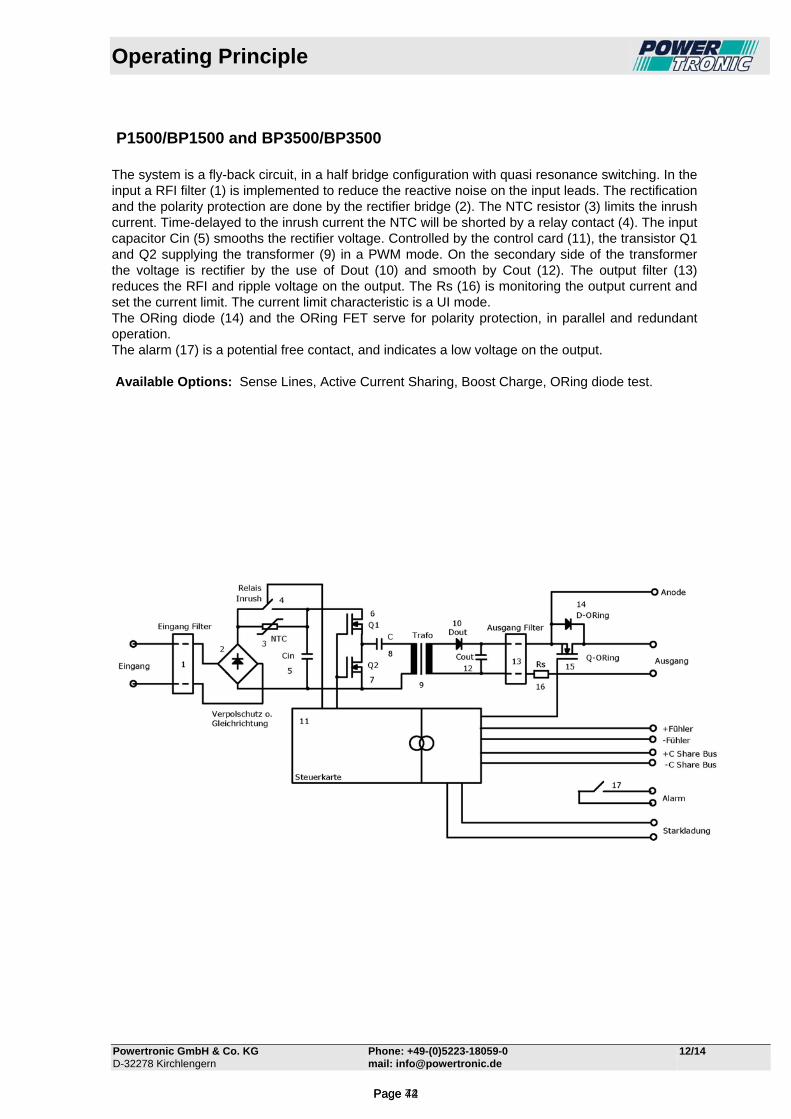
Operating Principle
Powertronic GmbH & Co. KG Phone: +49-(0)5223-18059-0 12/14 D-32278 Kirchlengern mail: [email protected]
P1500/BP1500 and BP3500/BP3500 The system is a fly-back circuit, in a half bridge configuration with quasi resonance switching. In the input a RFI filter (1) is implemented to reduce the reactive noise on the input leads. The rectification and the polarity protection are done by the rectifier bridge (2). The NTC resistor (3) limits the inrush current. Time-delayed to the inrush current the NTC will be shorted by a relay contact (4). The input capacitor Cin (5) smooths the rectifier voltage. Controlled by the control card (11), the transistor Q1 and Q2 supplying the transformer (9) in a PWM mode. On the secondary side of the transformer the voltage is rectifier by the use of Dout (10) and smooth by Cout (12). The output filter (13) reduces the RFI and ripple voltage on the output. The Rs (16) is monitoring the output current and set the current limit. The current limit characteristic is a UI mode. The ORing diode (14) and the ORing FET serve for polarity protection, in parallel and redundant operation. The alarm (17) is a potential free contact, and indicates a low voltage on the output. Available Options: Sense Lines, Active Current Sharing, Boost Charge, ORing diode test.
Page 44Page 72
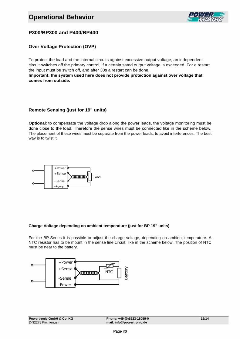
Operational Behavior
Powertronic GmbH & Co. KG Phone: +49-(0)5223-18059-0 12/14 D-32278 Kirchlengern mail: [email protected]
P300/BP300 and P400/BP400
Over Voltage Protection (OVP)
To protect the load and the internal circuits against excessive output voltage, an independent circuit switches off the primary control, if a certain sated output voltage is exceeded. For a restart the input must be switch off, and after 30s a restart can be done. Important: the system used here does not provide protection against over voltage that comes from outside.
Remote Sensing (just for 19” units)
Optional: to compensate the voltage drop along the power leads, the voltage monitoring must be done close to the load. Therefore the sense wires must be connected like in the scheme below. The placement of these wires must be separate from the power leads, to avoid interferences. The best way is to twist it.
Charge Voltage depending on ambient temperature (just for BP 19” units)
For the BP-Series it is possible to adjust the charge voltage, depending on ambient temperature. A NTC resistor has to be mount in the sense line circuit, like in the scheme below. The position of NTC must be near to the battery.
Page 45Page 73
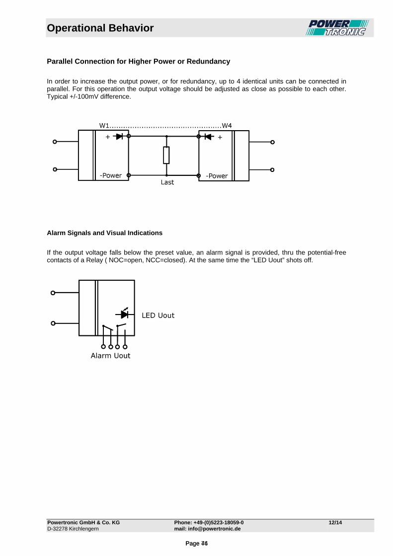
Operational Behavior
Powertronic GmbH & Co. KG Phone: +49-(0)5223-18059-0 12/14 D-32278 Kirchlengern mail: [email protected]
Parallel Connection for Higher Power or Redundancy
In order to increase the output power, or for redundancy, up to 4 identical units can be connected in parallel. For this operation the output voltage should be adjusted as close as possible to each other. Typical +/-100mV difference.
Alarm Signals and Visual Indications
If the output voltage falls below the preset value, an alarm signal is provided, thru the potential-free contacts of a Relay ( NOC=open, NCC=closed). At the same time the “LED Uout” shots off.
Page 46Page 74
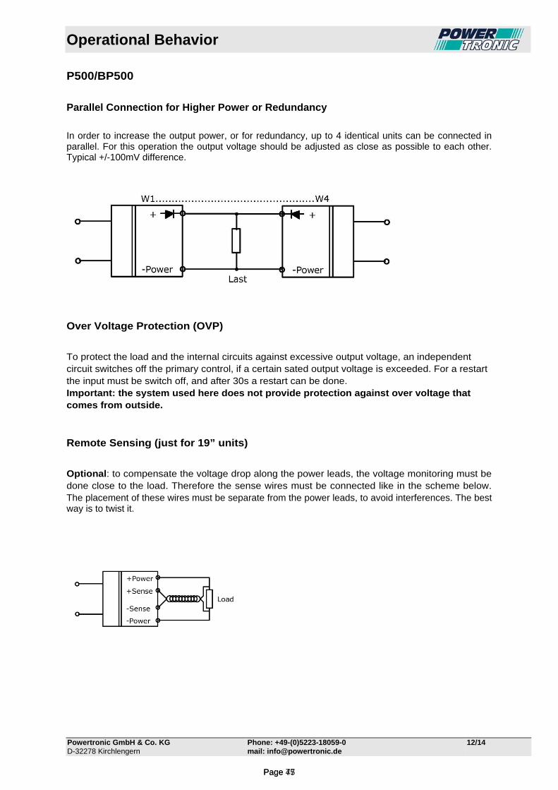
Operational Behavior
Powertronic GmbH & Co. KG Phone: +49-(0)5223-18059-0 12/14 D-32278 Kirchlengern mail: [email protected]
P500/BP500
Parallel Connection for Higher Power or Redundancy
In order to increase the output power, or for redundancy, up to 4 identical units can be connected in parallel. For this operation the output voltage should be adjusted as close as possible to each other. Typical +/-100mV difference.
Over Voltage Protection (OVP)
To protect the load and the internal circuits against excessive output voltage, an independent circuit switches off the primary control, if a certain sated output voltage is exceeded. For a restart the input must be switch off, and after 30s a restart can be done. Important: the system used here does not provide protection against over voltage that comes from outside. Remote Sensing (just for 19” units)
Optional: to compensate the voltage drop along the power leads, the voltage monitoring must be done close to the load. Therefore the sense wires must be connected like in the scheme below. The placement of these wires must be separate from the power leads, to avoid interferences. The best way is to twist it.
Page 47Page 75
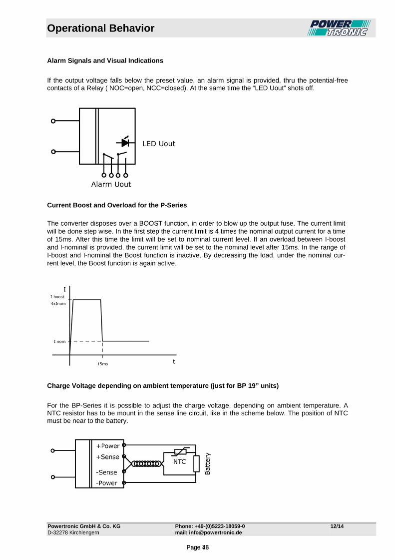
Operational Behavior
Powertronic GmbH & Co. KG Phone: +49-(0)5223-18059-0 12/14 D-32278 Kirchlengern mail: [email protected]
Alarm Signals and Visual Indications
If the output voltage falls below the preset value, an alarm signal is provided, thru the potential-free contacts of a Relay ( NOC=open, NCC=closed). At the same time the “LED Uout” shots off.
Current Boost and Overload for the P-Series
The converter disposes over a BOOST function, in order to blow up the output fuse. The current limit will be done step wise. In the first step the current limit is 4 times the nominal output current for a time of 15ms. After this time the limit will be set to nominal current level. If an overload between I-boost and I-nominal is provided, the current limit will be set to the nominal level after 15ms. In the range of I-boost and I-nominal the Boost function is inactive. By decreasing the load, under the nominal cur-rent level, the Boost function is again active.
Charge Voltage depending on ambient temperature (just for BP 19” units)
For the BP-Series it is possible to adjust the charge voltage, depending on ambient temperature. A NTC resistor has to be mount in the sense line circuit, like in the scheme below. The position of NTC must be near to the battery.
Page 48Page 76
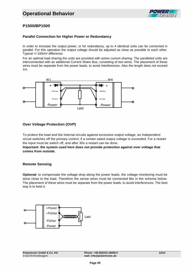
Operational Behavior
Powertronic GmbH & Co. KG Phone: +49-(0)5223-18059-0 12/14 D-32278 Kirchlengern mail: [email protected]
P1500/BP1500
Parallel Connection for Higher Power or Redundancy
In order to increase the output power, or for redundancy, up to 4 identical units can be connected in parallel. For this operation the output voltage should be adjusted as close as possible to each other. Typical +/-100mV difference.
For an optimal load sharing the units are provided with active current sharing. The paralleled units are interconnected with an additional Current Share Bus, consisting of two wires. The placement of these wires must be separate from the power leads, to avoid interferences. Also the length does not exceed 1m.
Over Voltage Protection (OVP)
To protect the load and the internal circuits against excessive output voltage, an independent circuit switches off the primary control, if a certain sated output voltage is exceeded. For a restart the input must be switch off, and after 30s a restart can be done. Important: the system used here does not provide protection against over voltage that comes from outside. Remote Sensing
Optional: to compensate the voltage drop along the power leads, the voltage monitoring must be done close to the load. Therefore the sense wires must be connected like in the scheme below. The placement of these wires must be separate from the power leads, to avoid interferences. The best way is to twist it.
Page 49Page 77
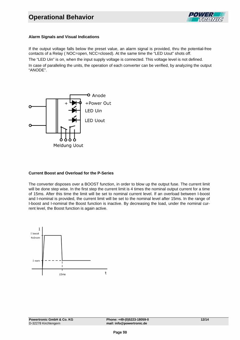
Operational Behavior
Powertronic GmbH & Co. KG Phone: +49-(0)5223-18059-0 12/14 D-32278 Kirchlengern mail: [email protected]
Alarm Signals and Visual Indications
If the output voltage falls below the preset value, an alarm signal is provided, thru the potential-free contacts of a Relay ( NOC=open, NCC=closed). At the same time the “LED Uout” shots off.
The “LED Uin” is on, when the input supply voltage is connected. This voltage level is not defined.
In case of paralleling the units, the operation of each converter can be verified, by analyzing the output “ANODE”.
Current Boost and Overload for the P-Series
The converter disposes over a BOOST function, in order to blow up the output fuse. The current limit will be done step wise. In the first step the current limit is 4 times the nominal output current for a time of 15ms. After this time the limit will be set to nominal current level. If an overload between I-boost and I-nominal is provided, the current limit will be set to the nominal level after 15ms. In the range of I-boost and I-nominal the Boost function is inactive. By decreasing the load, under the nominal cur-rent level, the Boost function is again active.
Page 50Page 78

Operational Behavior
Powertronic GmbH & Co. KG Phone: +49-(0)5223-18059-0 12/14 D-32278 Kirchlengern mail: [email protected]
Charge Voltage depending on ambient temperature (just for BP-Series)
For the BP-Series it is possible to adjust the charge voltage, depending on ambient temperature. A NTC resistor has to be mount in the sense line circuit, like in the scheme below. The position of NTC must be near to the battery.
Boost Charge (just for BP-Series)
For the BP-Series the setting of the charge voltage can be done with an external remote control volt-age. This input is potential free, and is controlled by an optocoupler. The function can be used for boost charge, or trickle charge.
Page 51Page 79

Operational Behavior
Powertronic GmbH & Co. KG Phone: +49-(0)5223-18059-0 12/14 D-32278 Kirchlengern mail: [email protected]
P3500/BP3500
Parallel Connection for Higher Power or Redundancy
In order to increase the output power, or for redundancy, up to 4 identical units can be connected in parallel. For this operation the output voltage should be adjusted as close as possible to each other. Typical +/-100mV difference.
For an optimal load sharing the units are provided with active current sharing. The paralleled units are interconnected with an additional Current Share Bus, consisting of two wires. The placement of these wires must be separate from the power leads, to avoid interferences. Also the length does not exceed 1m.
Over Voltage Protection (OVP)
To protect the load and the internal circuits against excessive output voltage, an independent circuit switches off the primary control, if a certain sated output voltage is exceeded. For a restart the input must be switch off, and after 30s a restart can be done. Important: the system used here does not provide protection against over voltage that comes from outside. Remote Sensing
Optional: to compensate the voltage drop along the power leads, the voltage monitoring must be done close to the load. Therefore the sense wires must be connected like in the scheme below. The placement of these wires must be separate from the power leads, to avoid interferences. The best way is to twist it.
Page 52Page 80

Operational Behavior
Powertronic GmbH & Co. KG Phone: +49-(0)5223-18059-0 12/14 D-32278 Kirchlengern mail: [email protected]
Alarm Signals and Visual Indications
If the output voltage falls below the preset value, an alarm signal is provided, thru the potential-free contacts of a Relay ( NOC=open, NCC=closed). At the same time the “LED Uout” shots off.
The “LED Uin” is on, when the input supply voltage is connected. This voltage level is not defined.
In case of paralleling the units, the operation of each converter can be verified, by analyzing the output “ANODE”.
Current Boost and Overload for the P-Series
The converter disposes over a BOOST function, in order to blow up the output fuse. The current limit will be done step wise. In the first step the current limit is 4 times the nominal output current for a time of 15ms. After this time the limit will be set to nominal current level. If an overload between I-boost and I-nominal is provided, the current limit will be set to the nominal level after 15ms. In the range of I-boost and I-nominal the Boost function is inactive. By decreasing the load, under the nominal cur-rent level, the Boost function is again active.
Page 53Page 81
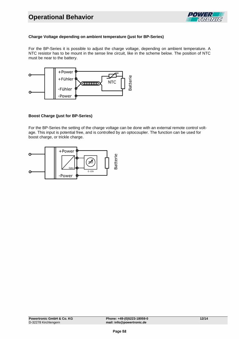
Operational Behavior
Powertronic GmbH & Co. KG Phone: +49-(0)5223-18059-0 12/14 D-32278 Kirchlengern mail: [email protected]
Charge Voltage depending on ambient temperature (just for BP-Series)
For the BP-Series it is possible to adjust the charge voltage, depending on ambient temperature. A NTC resistor has to be mount in the sense line circuit, like in the scheme below. The position of NTC must be near to the battery.
Boost Charge (just for BP-Series)
For the BP-Series the setting of the charge voltage can be done with an external remote control volt-age. This input is potential free, and is controlled by an optocoupler. The function can be used for boost charge, or trickle charge.
Page 54Page 82
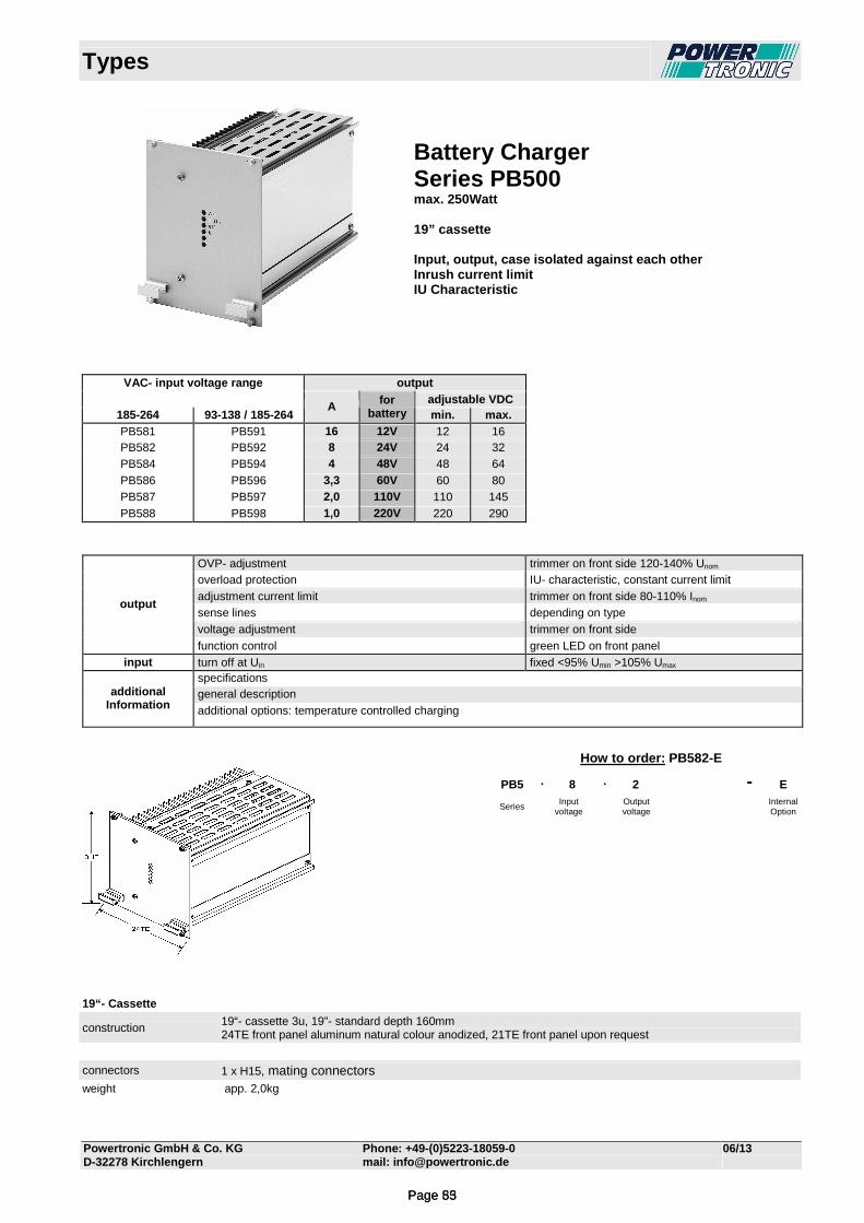
Types
Powertronic GmbH & Co. KG Phone: +49-(0)5223-18059-0 06/13 D-32278 Kirchlengern mail: [email protected]
Battery Charger Series PB500 max. 250Watt 19” cassette Input, output, case isolated against each other Inrush current limit IU Characteristic
VAC- input voltage range output adjustable VDC
185-264 93-138 / 185-264 A for
battery min. max.
PB581 PB591 16 12V 12 16 PB582 PB592 8 24V 24 32 PB584 PB594 4 48V 48 64 PB586 PB596 3,3 60V 60 80 PB587 PB597 2,0 110V 110 145 PB588 PB598 1,0 220V 220 290
OVP- adjustment trimmer on front side 120-140% Unom overload protection IU- characteristic, constant current limit adjustment current limit trimmer on front side 80-110% Inom sense lines depending on type voltage adjustment trimmer on front side
output
function control green LED on front panel input turn off at Uin fixed <95% Umin >105% Umax
specifications general description additional
Information additional options: temperature controlled charging
19“- Cassette
construction 19“- cassette 3u, 19”- standard depth 160mm 24TE front panel aluminum natural colour anodized, 21TE front panel upon request
connectors 1 x H15, mating connectors
weight app. 2,0kg
How to order: PB582-E
PB5 . 8 . 2 - E
Series Input
voltage Output voltage
Internal Option
Page 55Page 83
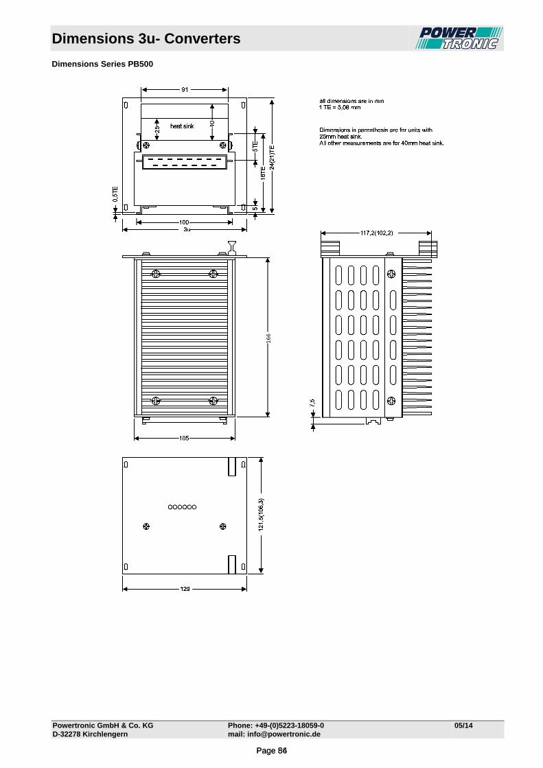
Dimensions 3u- Converters
Powertronic GmbH & Co. KG Phone: +49-(0)5223-18059-0 05/14
D-32278 Kirchlengern mail: [email protected]
Dimensions Series PB500
166
Page 56Page 84
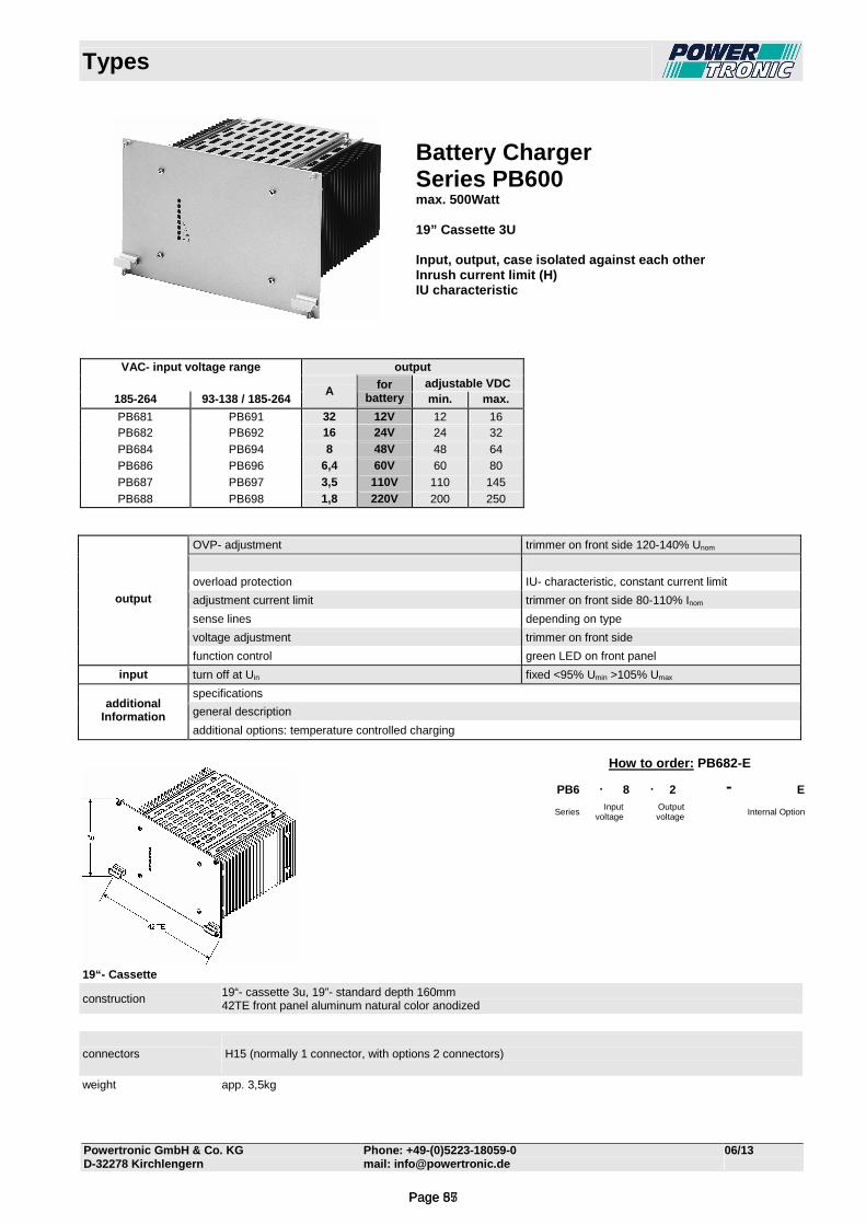
Types
Powertronic GmbH & Co. KG Phone: +49-(0)5223-18059-0 06/13 D-32278 Kirchlengern mail: [email protected]
Battery Charger Series PB600 max. 500Watt 19” Cassette 3U Input, output, case isolated against each other Inrush current limit (H) IU characteristic
VAC- input voltage range output adjustable VDC
185-264 93-138 / 185-264 A for
battery min. max.
PB681 PB691 32 12V 12 16 PB682 PB692 16 24V 24 32 PB684 PB694 8 48V 48 64 PB686 PB696 6,4 60V 60 80 PB687 PB697 3,5 110V 110 145 PB688 PB698 1,8 220V 200 250
OVP- adjustment trimmer on front side 120-140% Unom
overload protection IU- characteristic, constant current limit
adjustment current limit trimmer on front side 80-110% Inom
sense lines depending on type
voltage adjustment trimmer on front side
output
function control green LED on front panel
input turn off at Uin fixed <95% Umin >105% Umax
specifications
general description additional
Information additional options: temperature controlled charging
19“- Cassette
construction 19“- cassette 3u, 19”- standard depth 160mm 42TE front panel aluminum natural color anodized
connectors H15 (normally 1 connector, with options 2 connectors)
weight app. 3,5kg
How to order: PB682-E
PB6 . 8 . 2 - E
Series Input
voltage Output
voltage Internal Option
Page 57Page 85

Dimensions 3u- Converters
Powertronic GmbH & Co. KG Phone: +49-(0)5223-18059-0 05/14
D-32278 Kirchlengern mail: [email protected]
Dimensions Series PB600
166
Page 58Page 86
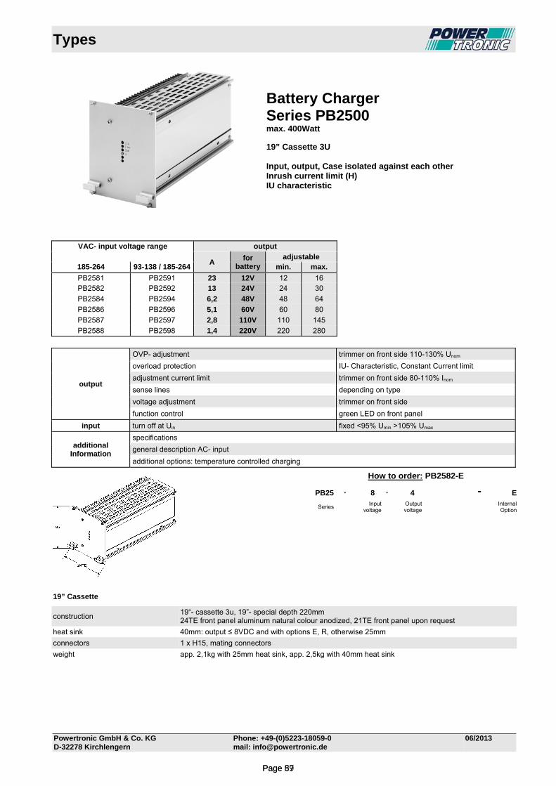
Types
Powertronic GmbH & Co. KG Phone: +49-(0)5223-18059-0 06/2013 D-32278 Kirchlengern mail: [email protected]
Battery Charger Series PB2500 max. 400Watt 19” Cassette 3U Input, output, Case isolated against each other Inrush current limit (H) IU characteristic
VAC- input voltage range output
A
for battery
adjustable 185-264 93-138 / 185-264 min. max.
PB2581 PB2591 23 12V 12 16 PB2582 PB2592 13 24V 24 30
PB2584 PB2594 6,2 48V 48 64
PB2586 PB2596 5,1 60V 60 80
PB2587 PB2597 2,8 110V 110 145
PB2588 PB2598 1,4 220V 220 280
output
OVP- adjustment trimmer on front side 110-130% Unom
overload protection IU- Characteristic, Constant Current limit
adjustment current limit trimmer on front side 80-110% Inom
sense lines depending on type
voltage adjustment trimmer on front side
function control green LED on front panel
input turn off at Uin fixed <95% Umin >105% Umax
additional Information
specifications
general description AC- input
additional options: temperature controlled charging
19” Cassette
construction 19“- cassette 3u, 19”- special depth 220mm 24TE front panel aluminum natural colour anodized, 21TE front panel upon request
heat sink 40mm: output ≤ 8VDC and with options E, R, otherwise 25mm
connectors 1 x H15, mating connectors
weight app. 2,1kg with 25mm heat sink, app. 2,5kg with 40mm heat sink
How to order: PB2582-E
PB25 . 8 . 4 - E
Series Input
voltage Output voltage
Internal Option
Page 59Page 87
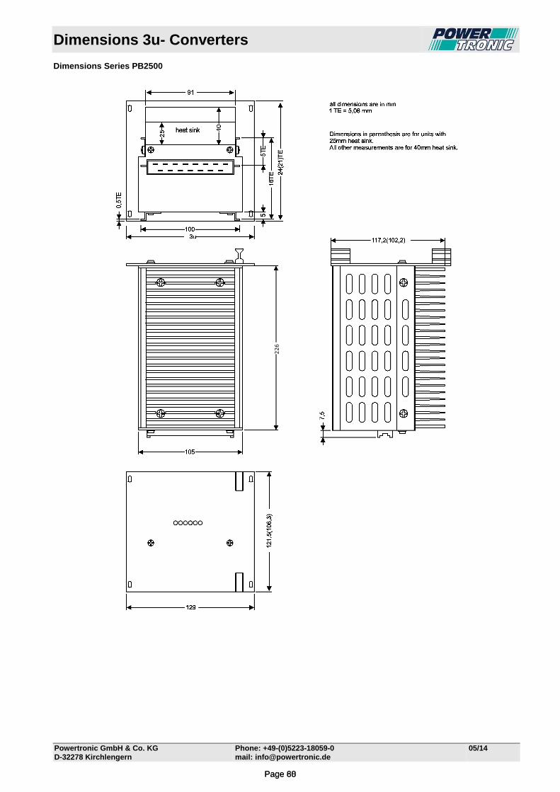
Dimensions 3u- Converters
Powertronic GmbH & Co. KG Phone: +49-(0)5223-18059-0 05/14
D-32278 Kirchlengern mail: [email protected]
Dimensions Series PB2500
226
Page 60Page 88
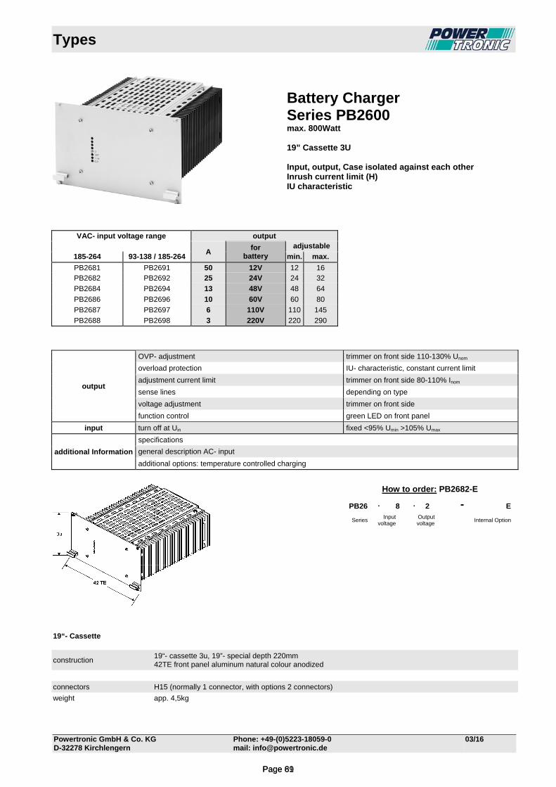
Types
Powertronic GmbH & Co. KG Phone: +49-(0)5223-18059-0 03/16 D-32278 Kirchlengern mail: [email protected]
Battery Charger Series PB2600 max. 800Watt 19” Cassette 3U Input, output, Case isolated against each other Inrush current limit (H) IU characteristic
VAC- input voltage range output
A
for battery
adjustable
185-264 93-138 / 185-264 min. max.
PB2681 PB2691 50 12V 12 16 PB2682 PB2692 25 24V 24 32
PB2684 PB2694 13 48V 48 64
PB2686 PB2696 10 60V 60 80
PB2687 PB2697 6 110V 110 145
PB2688 PB2698 3 220V 220 290
output
OVP- adjustment trimmer on front side 110-130% Unom
overload protection IU- characteristic, constant current limit
adjustment current limit trimmer on front side 80-110% Inom
sense lines depending on type
voltage adjustment trimmer on front side
function control green LED on front panel
input turn off at Uin fixed <95% Umin >105% Umax
additional Information
specifications
general description AC- input
additional options: temperature controlled charging
19“- Cassette
How to order: PB2682-E
PB26 . 8 . 2 - E
Series Input
voltage Output
voltage Internal Option
construction 19“- cassette 3u, 19”- special depth 220mm 42TE front panel aluminum natural colour anodized
connectors H15 (normally 1 connector, with options 2 connectors)
weight app. 4,5kg
Page 61Page 89
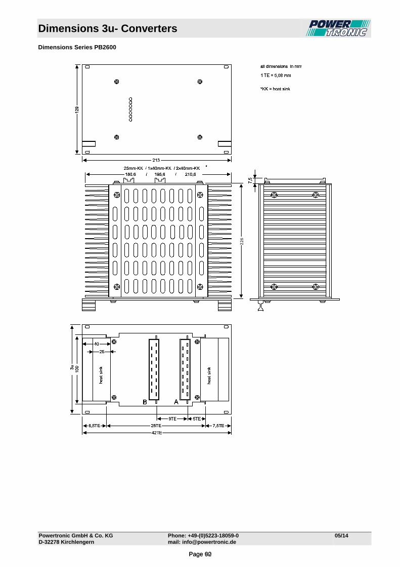
Dimensions 3u- Converters
Powertronic GmbH & Co. KG Phone: +49-(0)5223-18059-0 05/14
D-32278 Kirchlengern mail: [email protected]
Dimensions Series PB2600
226
Page 62Page 90
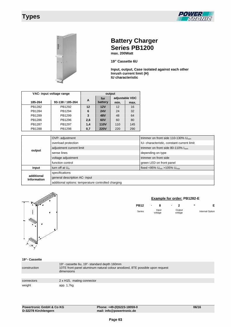
Types
Powertronic GmbH & Co KG Phone: +49-(0)5223-18059-0 06/16 D-32278 Kirchlengern mail: [email protected]
Battery Charger Series PB1200 max. 200Watt 19” Cassette 6U Input, output, Case isolated against each other Inrush current limit (H) IU characteristic
VAC- input voltage range output
A
for battery
adjustable VDC 185-264 93-138 / 185-264 min. max.
PB1282 PB1292 12 12V 12 16 PB1284 PB1294 6 24V 24 32
PB1289 PB1299 3 48V 48 64
PB1286 PB1296 2,6 60V 60 80
PB1287 PB1297 1,4 110V 110 145
PB1288 PB1298 0,7 220V 220 290
output
OVP- adjustment trimmer on front side 110-130% Unom
overload protection IU- characteristic, constant current limit
adjustment current limit trimmer on front side 80-110% Inom
sense lines depending on type
voltage adjustment trimmer on front side
function control green LED on front panel
input turn off at Uin fixed <95% Umin >105% Umax
additional Information
specifications
general description AC- input
additional options: temperature controlled charging
19“- Cassette
construction 19“- cassette 6u, 19”- standard depth 160mm 10TE front panel aluminum natural colour anodized, 8TE possible upon request dimensions
connectors 2 x H15, mating connector
weight app. 1,7kg
Example for order: PB1282-E
PB12 . 8 . 2 - E
Series Input
voltage Output voltage
Internal Option
Page 63Page 91
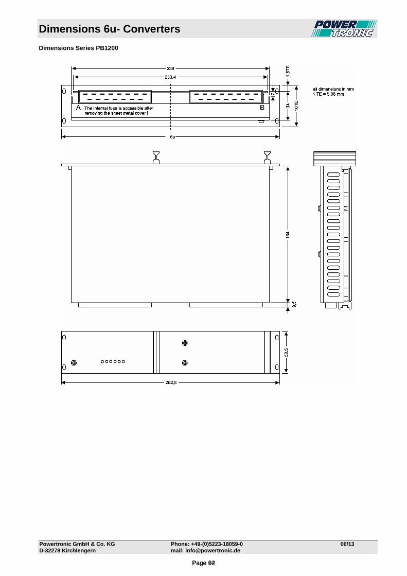
Dimensions 6u- Converters
Powertronic GmbH & Co. KG Phone: +49-(0)5223-18059-0 06/13 D-32278 Kirchlengern mail: [email protected]
Dimensions Series PB1200
Page 64Page 92
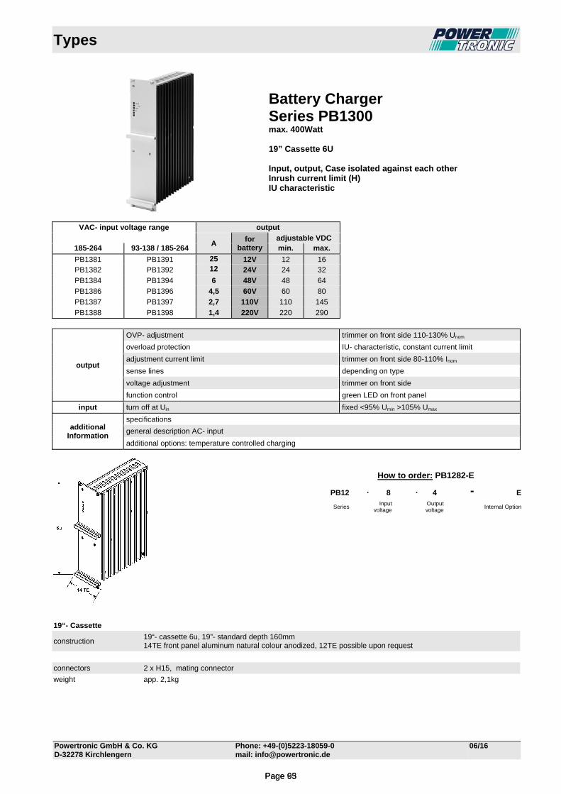
Types
Powertronic GmbH & Co. KG Phone: +49-(0)5223-18059-0 06/16 D-32278 Kirchlengern mail: [email protected]
Battery Charger Series PB1300 max. 400Watt 19” Cassette 6U Input, output, Case isolated against each other Inrush current limit (H) IU characteristic
VAC- input voltage range output
A
for battery
adjustable VDC 185-264 93-138 / 185-264 min. max.
PB1381 PB1391 25 12V 12 16 PB1382 PB1392 12 24V 24 32
PB1384 PB1394 6 48V 48 64
PB1386 PB1396 4,5 60V 60 80
PB1387 PB1397 2,7 110V 110 145
PB1388 PB1398 1,4 220V 220 290
output
OVP- adjustment trimmer on front side 110-130% Unom
overload protection IU- characteristic, constant current limit
adjustment current limit trimmer on front side 80-110% Inom
sense lines depending on type
voltage adjustment trimmer on front side
function control green LED on front panel
input turn off at Uin fixed <95% Umin >105% Umax
additional Information
specifications
general description AC- input
additional options: temperature controlled charging
19“- Cassette
construction 19“- cassette 6u, 19”- standard depth 160mm 14TE front panel aluminum natural colour anodized, 12TE possible upon request
connectors 2 x H15, mating connector
weight app. 2,1kg
How to order: PB1282-E
PB12 . 8 . 4 - E
Series Input
voltage Output
voltage Internal Option
Page 65Page 93
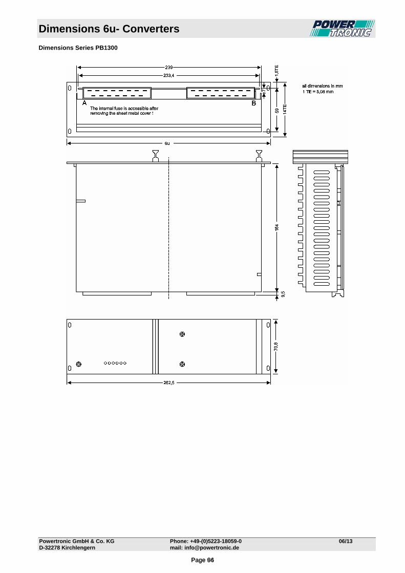
Dimensions 6u- Converters
Powertronic GmbH & Co. KG Phone: +49-(0)5223-18059-0 06/13 D-32278 Kirchlengern mail: [email protected]
Dimensions Series PB1300
Page 66Page 94
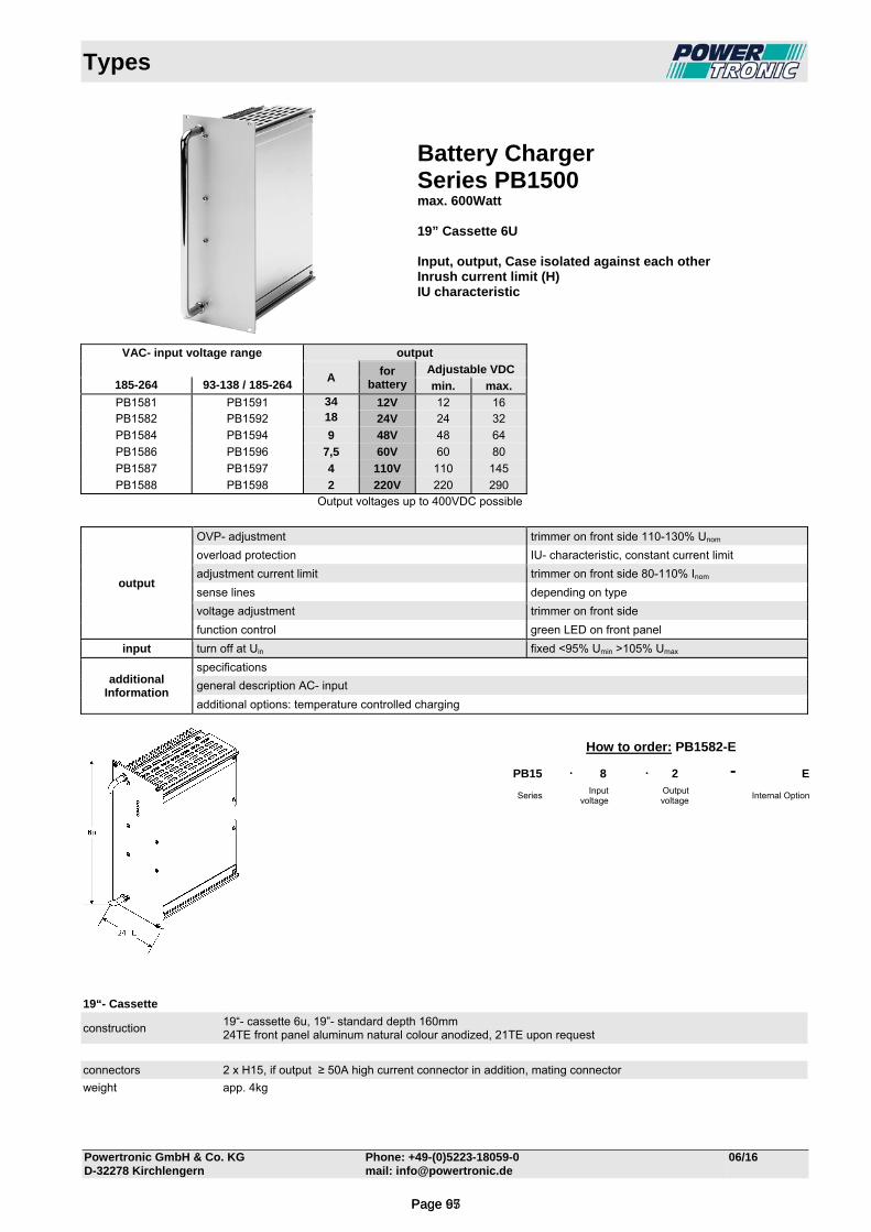
Types
Powertronic GmbH & Co. KG Phone: +49-(0)5223-18059-0 06/16 D-32278 Kirchlengern mail: [email protected]
Battery Charger Series PB1500 max. 600Watt 19” Cassette 6U Input, output, Case isolated against each other Inrush current limit (H) IU characteristic
VAC- input voltage range output
A
for battery
Adjustable VDC 185-264 93-138 / 185-264 min. max.
PB1581 PB1591 34 12V 12 16 PB1582 PB1592 18 24V 24 32
PB1584 PB1594 9 48V 48 64
PB1586 PB1596 7,5 60V 60 80
PB1587 PB1597 4 110V 110 145
PB1588 PB1598 2 220V 220 290 Output voltages up to 400VDC possible
output
OVP- adjustment trimmer on front side 110-130% Unom
overload protection IU- characteristic, constant current limit
adjustment current limit trimmer on front side 80-110% Inom
sense lines depending on type
voltage adjustment trimmer on front side
function control green LED on front panel
input turn off at Uin fixed <95% Umin >105% Umax
additional Information
specifications
general description AC- input
additional options: temperature controlled charging
19“- Cassette
construction 19“- cassette 6u, 19”- standard depth 160mm 24TE front panel aluminum natural colour anodized, 21TE upon request
connectors 2 x H15, if output ≥ 50A high current connector in addition, mating connector
weight app. 4kg
How to order: PB1582-E
PB15 . 8 . 2 - E
Series Input
voltage Output voltage
Internal Option
Page 67Page 95

Dimensions 6u- Converters
Powertronic GmbH & Co. KG Phone: +49-(0)5223-18059-0 05/14
D-32278 Kirchlengern mail: [email protected]
Dimensions Series PB1500
166
Page 68Page 96
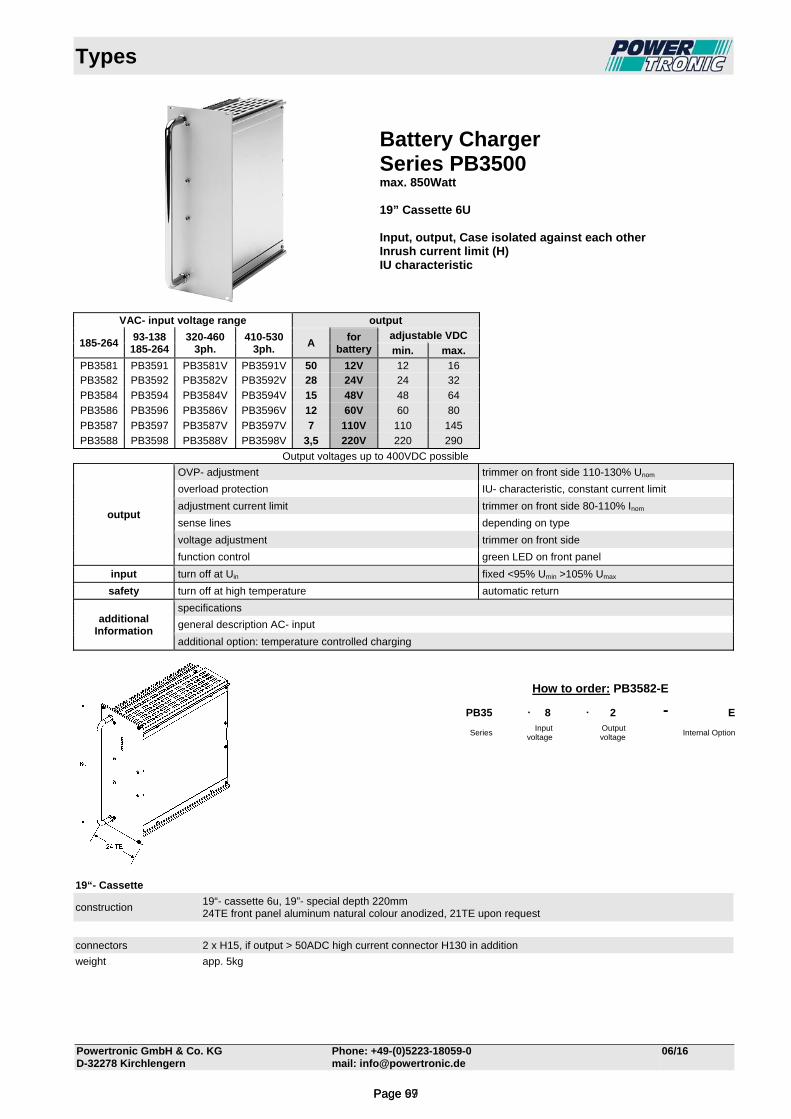
Types
Powertronic GmbH & Co. KG Phone: +49-(0)5223-18059-0 06/16 D-32278 Kirchlengern mail: [email protected]
Battery Charger Series PB3500 max. 850Watt 19” Cassette 6U Input, output, Case isolated against each other Inrush current limit (H) IU characteristic
VAC- input voltage range output
185-264
93-138 185-264
320-460 3ph.
410-530 3ph.
A for
batteryadjustable VDC
min. max.
PB3581 PB3591 PB3581V PB3591V 50 12V 12 16 PB3582 PB3592 PB3582V PB3592V 28 24V 24 32
PB3584 PB3594 PB3584V PB3594V 15 48V 48 64
PB3586 PB3596 PB3586V PB3596V 12 60V 60 80
PB3587 PB3597 PB3587V PB3597V 7 110V 110 145
PB3588 PB3598 PB3588V PB3598V 3,5 220V 220 290
Output voltages up to 400VDC possible
output
OVP- adjustment trimmer on front side 110-130% Unom
overload protection IU- characteristic, constant current limit
adjustment current limit trimmer on front side 80-110% Inom
sense lines depending on type
voltage adjustment trimmer on front side
function control green LED on front panel
input turn off at Uin fixed <95% Umin >105% Umax
safety turn off at high temperature automatic return
additional Information
specifications
general description AC- input
additional option: temperature controlled charging
19“- Cassette
construction 19“- cassette 6u, 19”- special depth 220mm 24TE front panel aluminum natural colour anodized, 21TE upon request
connectors 2 x H15, if output > 50ADC high current connector H130 in addition
weight app. 5kg
How to order: PB3582-E
PB35 . 8 . 2 - E
Series Input
voltage Output voltage
Internal Option
Page 69Page 97

Dimensions 6u- Converters
Powertronic GmbH & Co. KG Phone: +49-(0)5223-18059-0 05/14
D-32278 Kirchlengern mail: [email protected]
Dimensions Series PB3500
226
Page 70Page 98
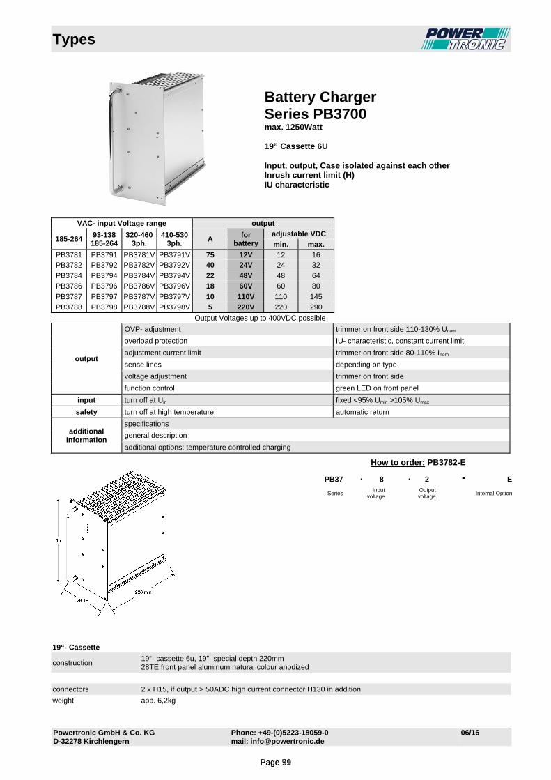
Types
Powertronic GmbH & Co. KG Phone: +49-(0)5223-18059-0 06/16 D-32278 Kirchlengern mail: [email protected]
Battery Charger Series PB3700 max. 1250Watt 19” Cassette 6U Input, output, Case isolated against each other Inrush current limit (H) IU characteristic
VAC- input Voltage range output
185-264
93-138 185-264
320-460 3ph.
410-530 3ph.
A for
battery adjustable VDC
min. max.
PB3781 PB3791 PB3781V PB3791V 75 12V 12 16 PB3782 PB3792 PB3782V PB3792V 40 24V 24 32
PB3784 PB3794 PB3784V PB3794V 22 48V 48 64
PB3786 PB3796 PB3786V PB3796V 18 60V 60 80
PB3787 PB3797 PB3787V PB3797V 10 110V 110 145
PB3788 PB3798 PB3788V PB3798V 5 220V 220 290
Output Voltages up to 400VDC possible
output
OVP- adjustment trimmer on front side 110-130% Unom
overload protection IU- characteristic, constant current limit
adjustment current limit trimmer on front side 80-110% Inom
sense lines depending on type
voltage adjustment trimmer on front side
function control green LED on front panel
input turn off at Uin fixed <95% Umin >105% Umax
safety turn off at high temperature automatic return
additional Information
specifications
general description
additional options: temperature controlled charging
19“- Cassette
construction 19“- cassette 6u, 19”- special depth 220mm 28TE front panel aluminum natural colour anodized
connectors 2 x H15, if output > 50ADC high current connector H130 in addition
weight app. 6,2kg
How to order: PB3782-E
PB37 . 8 . 2 - E
Series Input
voltage Output voltage
Internal Option
Page 71Page 99

Dimensions 6u- Converters
Powertronic GmbH & Co. KG Phone: +49-(0)5223-18059-0 05/14
D-32278 Kirchlengern mail: [email protected]
Dimensions Series PB3700
226
Page 72Page 100
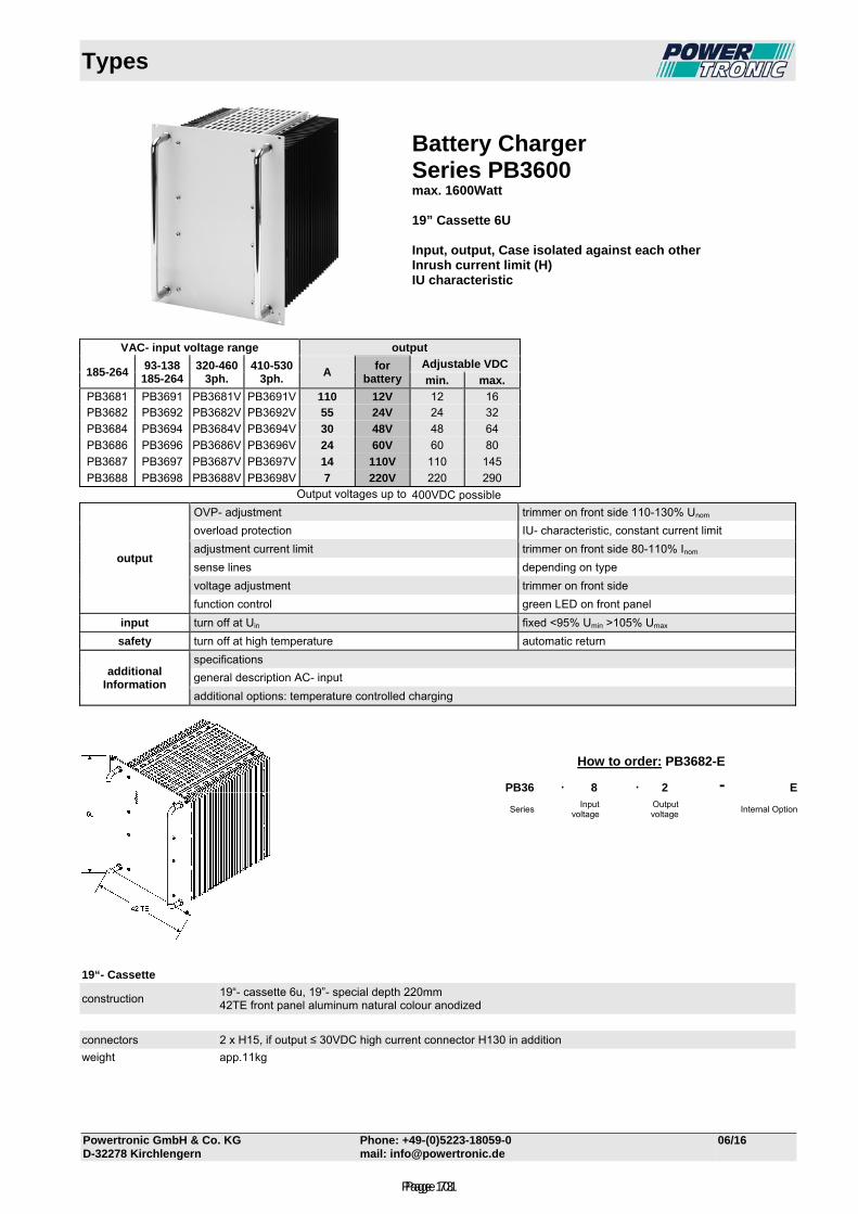
Types
Powertronic GmbH & Co. KG Phone: +49-(0)5223-18059-0 06/16 D-32278 Kirchlengern mail: [email protected]
Battery Charger Series PB3600 max. 1600Watt 19” Cassette 6U Input, output, Case isolated against each other Inrush current limit (H) IU characteristic
VAC- input voltage range output
185-264
93-138 185-264
320-460 3ph.
410-530 3ph.
A for
battery Adjustable VDC
min. max.
PB3681 PB3691 PB3681V PB3691V 110 12V 12 16 PB3682 PB3692 PB3682V PB3692V 55 24V 24 32
PB3684 PB3694 PB3684V PB3694V 30 48V 48 64
PB3686 PB3696 PB3686V PB3696V 24 60V 60 80
PB3687 PB3697 PB3687V PB3697V 14 110V 110 145
PB3688 PB3698 PB3688V PB3698V 7 220V 220 290 Output voltages up to 400VDC possible
output
OVP- adjustment trimmer on front side 110-130% Unom
overload protection IU- characteristic, constant current limit
adjustment current limit trimmer on front side 80-110% Inom
sense lines depending on type
voltage adjustment trimmer on front side
function control green LED on front panel
input turn off at Uin fixed <95% Umin >105% Umax
safety turn off at high temperature automatic return
additional Information
specifications
general description AC- input
additional options: temperature controlled charging
19“- Cassette
construction 19“- cassette 6u, 19”- special depth 220mm 42TE front panel aluminum natural colour anodized
connectors 2 x H15, if output ≤ 30VDC high current connector H130 in addition
weight app.11kg
How to order: PB3682-E
PB36 . 8 . 2 - E
Series Input
voltage Output voltage
Internal Option
Page 73Page 101
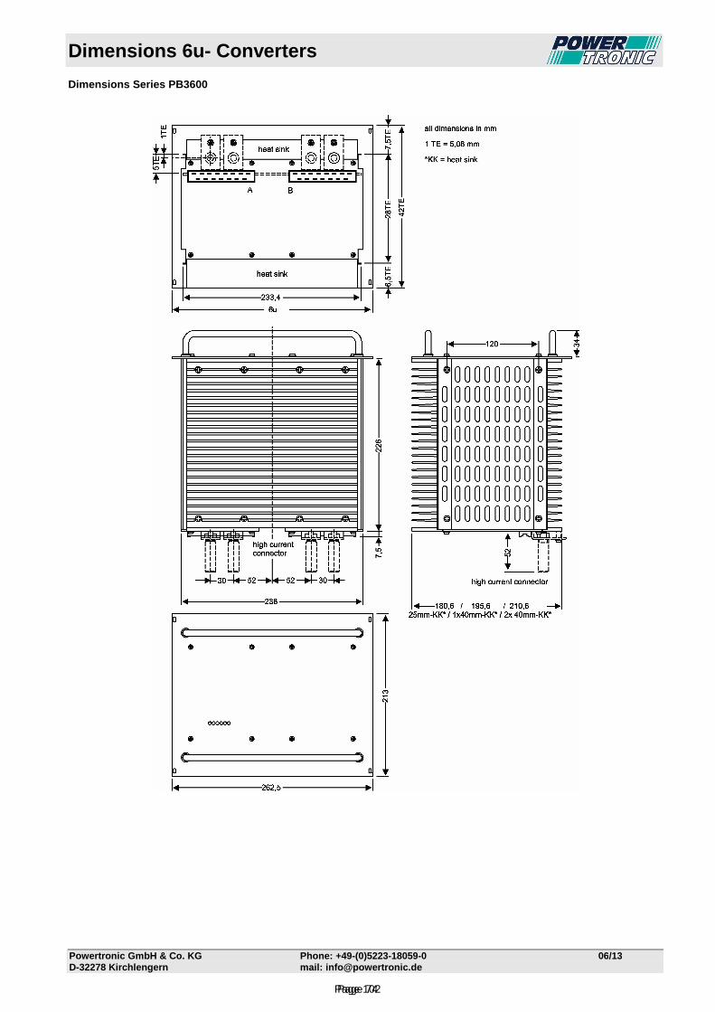
Dimensions 6u- Converters
Powertronic GmbH & Co. KG Phone: +49-(0)5223-18059-0 06/13 D-32278 Kirchlengern mail: [email protected]
Dimensions Series PB3600
Page 74Page 102
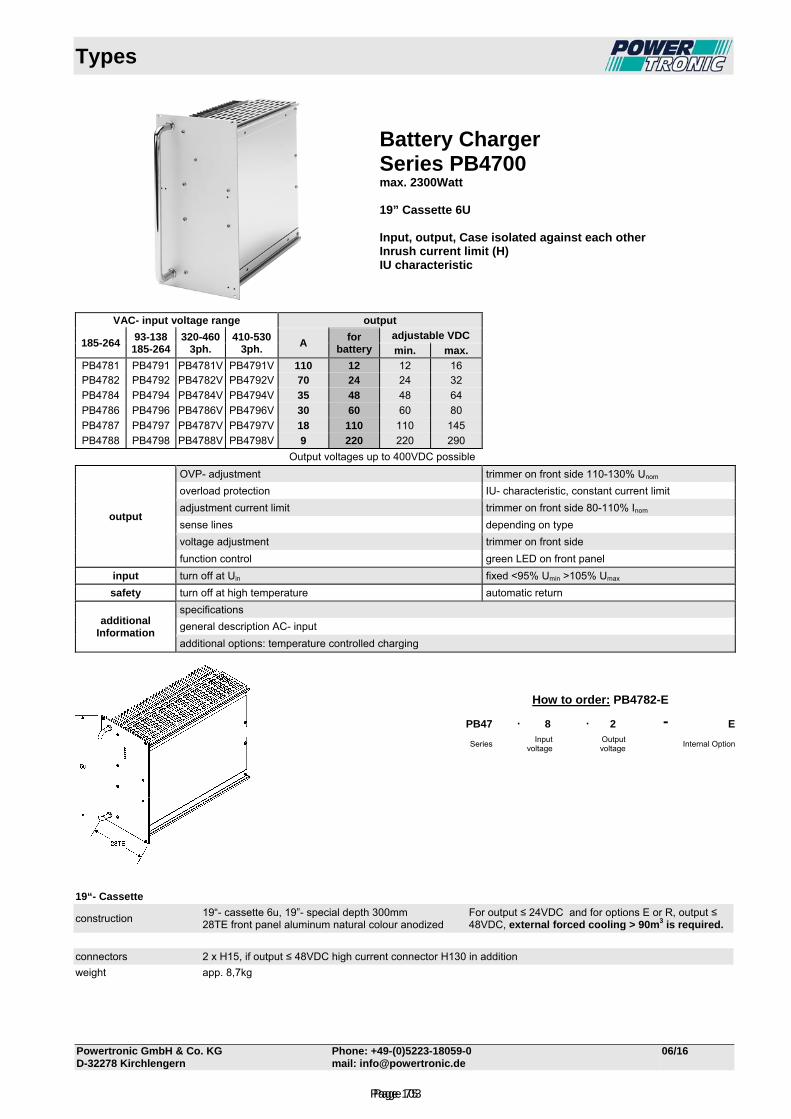
Types
Powertronic GmbH & Co. KG Phone: +49-(0)5223-18059-0 06/16 D-32278 Kirchlengern mail: [email protected]
Battery Charger Series PB4700 max. 2300Watt 19” Cassette 6U Input, output, Case isolated against each other Inrush current limit (H) IU characteristic
VAC- input voltage range output
185-264
93-138 185-264
320-460 3ph.
410-530 3ph.
A for
battery adjustable VDC
min. max.
PB4781 PB4791 PB4781V PB4791V 110 12 12 16 PB4782 PB4792 PB4782V PB4792V 70 24 24 32
PB4784 PB4794 PB4784V PB4794V 35 48 48 64
PB4786 PB4796 PB4786V PB4796V 30 60 60 80
PB4787 PB4797 PB4787V PB4797V 18 110 110 145
PB4788 PB4798 PB4788V PB4798V 9 220 220 290
Output voltages up to 400VDC possible
output
OVP- adjustment trimmer on front side 110-130% Unom
overload protection IU- characteristic, constant current limit
adjustment current limit trimmer on front side 80-110% Inom
sense lines depending on type
voltage adjustment trimmer on front side
function control green LED on front panel
input turn off at Uin fixed <95% Umin >105% Umax
safety turn off at high temperature automatic return
additional Information
specifications
general description AC- input
additional options: temperature controlled charging
19“- Cassette
construction 19“- cassette 6u, 19”- special depth 300mm 28TE front panel aluminum natural colour anodized
For output ≤ 24VDC and for options E or R, output ≤ 48VDC, external forced cooling > 90m3 is required.
connectors 2 x H15, if output ≤ 48VDC high current connector H130 in addition
weight app. 8,7kg
How to order: PB4782-E
PB47 . 8 . 2 - E
Series Input
voltage Output voltage
Internal Option
Page 75Page 103
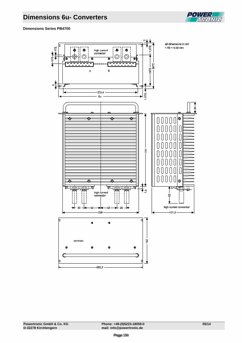
Dimensions 6u- Converters
Powertronic GmbH & Co. KG Phone: +49-(0)5223-18059-0 05/14
D-32278 Kirchlengern mail: [email protected]
Dimensions Series PB4700
306
Page 76Page 104
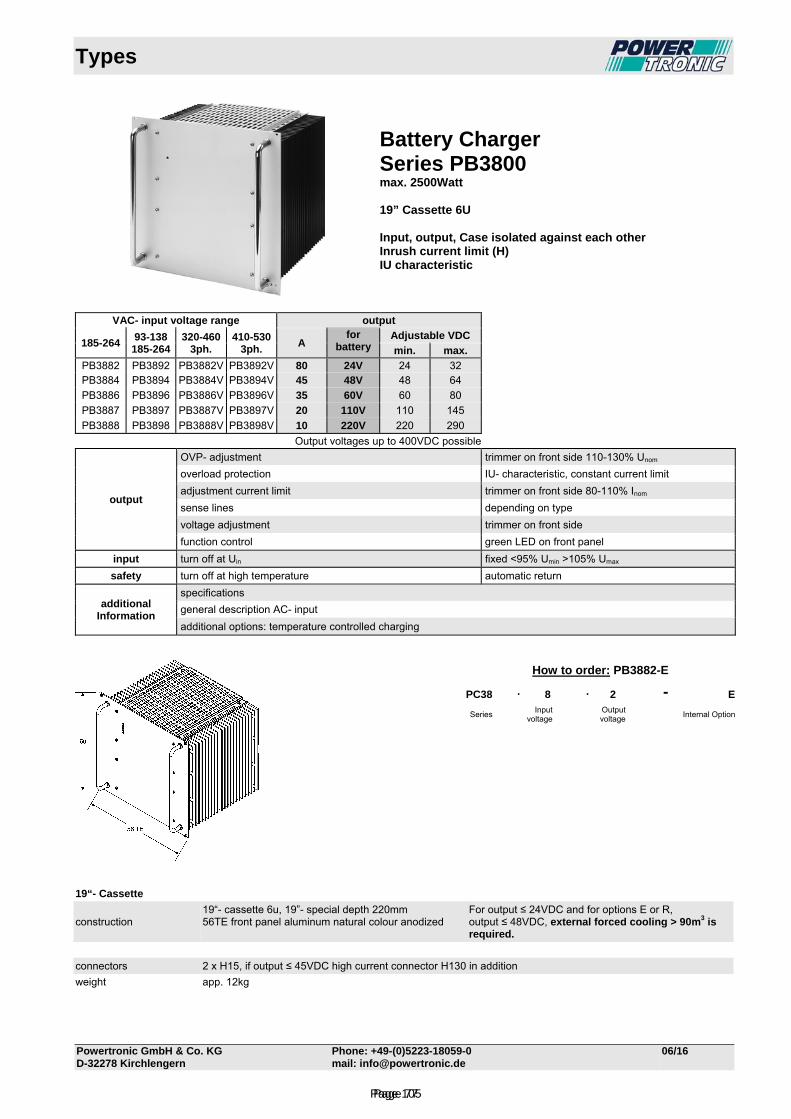
Types
Powertronic GmbH & Co. KG Phone: +49-(0)5223-18059-0 06/16 D-32278 Kirchlengern mail: [email protected]
Battery Charger Series PB3800 max. 2500Watt 19” Cassette 6U Input, output, Case isolated against each other Inrush current limit (H) IU characteristic
VAC- input voltage range output
185-264
93-138 185-264
320-460 3ph.
410-530 3ph.
A for
battery Adjustable VDC
min. max.
PB3882 PB3892 PB3882V PB3892V 80 24V 24 32 PB3884 PB3894 PB3884V PB3894V 45 48V 48 64
PB3886 PB3896 PB3886V PB3896V 35 60V 60 80
PB3887 PB3897 PB3887V PB3897V 20 110V 110 145
PB3888 PB3898 PB3888V PB3898V 10 220V 220 290
Output voltages up to 400VDC possible
output
OVP- adjustment trimmer on front side 110-130% Unom
overload protection IU- characteristic, constant current limit
adjustment current limit trimmer on front side 80-110% Inom
sense lines depending on type
voltage adjustment trimmer on front side
function control green LED on front panel
input turn off at Uin fixed <95% Umin >105% Umax
safety turn off at high temperature automatic return
additional Information
specifications
general description AC- input
additional options: temperature controlled charging
19“- Cassette
construction 19“- cassette 6u, 19”- special depth 220mm 56TE front panel aluminum natural colour anodized
For output ≤ 24VDC and for options E or R, output ≤ 48VDC, external forced cooling > 90m3 is required.
connectors 2 x H15, if output ≤ 45VDC high current connector H130 in addition
weight app. 12kg
How to order: PB3882-E
PC38 . 8 . 2 - E
Series Input
voltage Output voltage
Internal Option
Page 77Page 105

Dimensions 6u- Converters
Powertronic GmbH & Co. KG Phone: +49-(0)5223-18059-0 05/14
D-32278 Kirchlengern mail: [email protected]
Dimensions Series PB3800
226
Page 78Page 106
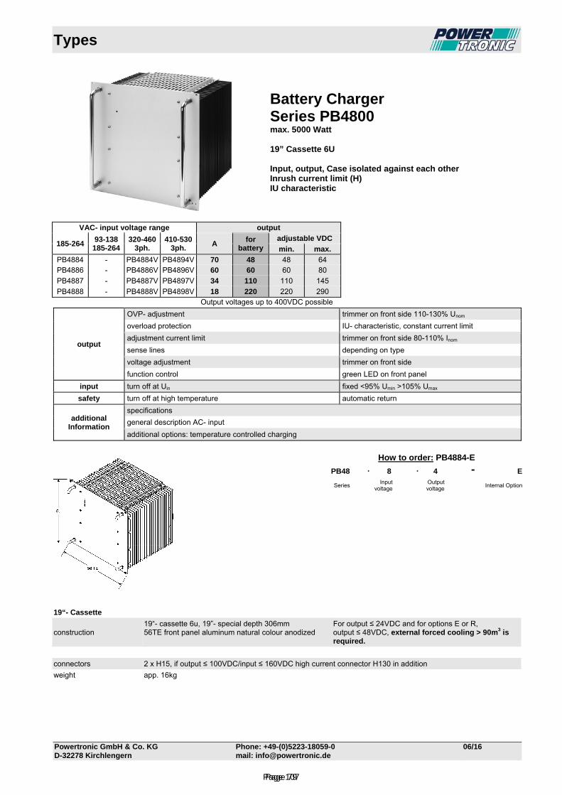
Types
Powertronic GmbH & Co. KG Phone: +49-(0)5223-18059-0 06/16 D-32278 Kirchlengern mail: [email protected]
Battery Charger Series PB4800 max. 5000 Watt 19” Cassette 6U Input, output, Case isolated against each other Inrush current limit (H) IU characteristic
VAC- input voltage range output
185-264
93-138 185-264
320-460 3ph.
410-530 3ph.
A for
battery adjustable VDC
min. max.
PB4884 - PB4884V PB4894V 70 48 48 64 PB4886 - PB4886V PB4896V 60 60 60 80
PB4887 - PB4887V PB4897V 34 110 110 145
PB4888 - PB4888V PB4898V 18 220 220 290 Output voltages up to 400VDC possible
output
OVP- adjustment trimmer on front side 110-130% Unom
overload protection IU- characteristic, constant current limit
adjustment current limit trimmer on front side 80-110% Inom
sense lines depending on type
voltage adjustment trimmer on front side
function control green LED on front panel
input turn off at Uin fixed <95% Umin >105% Umax
safety turn off at high temperature automatic return
additional Information
specifications
general description AC- input
additional options: temperature controlled charging
19“- Cassette
construction 19“- cassette 6u, 19”- special depth 306mm 56TE front panel aluminum natural colour anodized
For output ≤ 24VDC and for options E or R, output ≤ 48VDC, external forced cooling > 90m3 is required.
connectors 2 x H15, if output ≤ 100VDC/input ≤ 160VDC high current connector H130 in addition
weight app. 16kg
How to order: PB4884-E
PB48 . 8 . 4 - E
Series Input
voltage Output voltage
Internal Option
Page 79Page 107
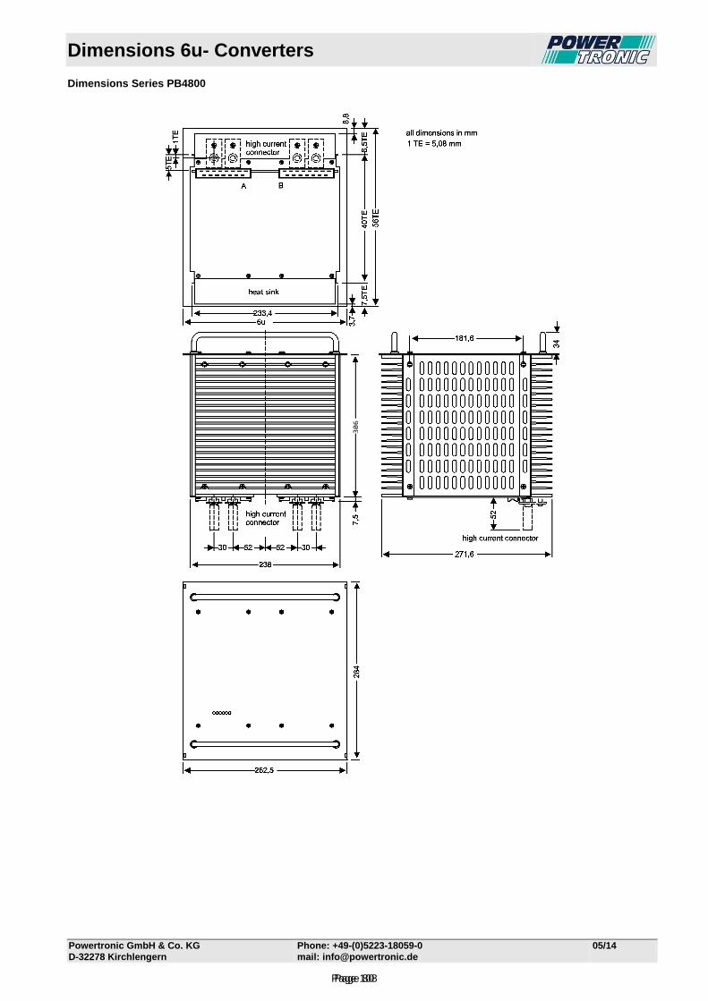
Dimensions 6u- Converters
Powertronic GmbH & Co. KG Phone: +49-(0)5223-18059-0 05/14
D-32278 Kirchlengern mail: [email protected]
Dimensions Series PB4800
306
Page 80Page 108
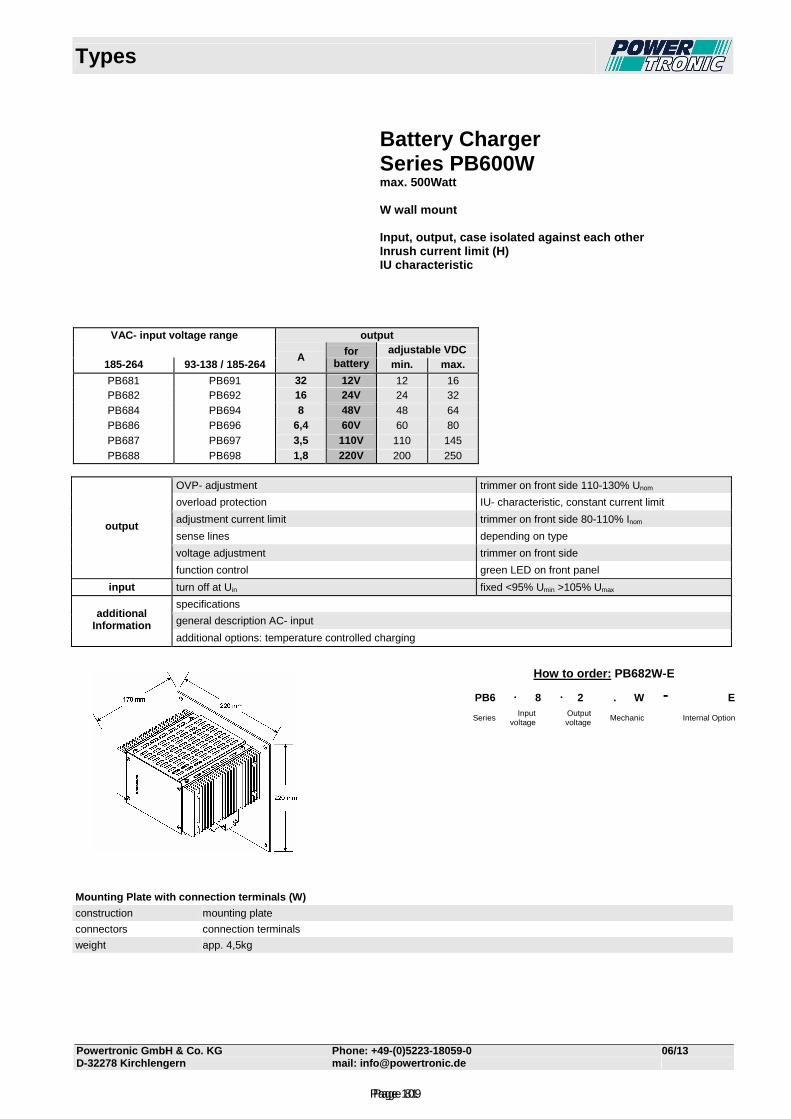
Types
Powertronic GmbH & Co. KG Phone: +49-(0)5223-18059-0 06/13 D-32278 Kirchlengern mail: [email protected]
Battery Charger Series PB600W max. 500Watt W wall mount Input, output, case isolated against each other Inrush current limit (H) IU characteristic
VAC- input voltage range output adjustable VDC
185-264 93-138 / 185-264 A for
battery min. max.
PB681 PB691 32 12V 12 16 PB682 PB692 16 24V 24 32 PB684 PB694 8 48V 48 64 PB686 PB696 6,4 60V 60 80 PB687 PB697 3,5 110V 110 145 PB688 PB698 1,8 220V 200 250
OVP- adjustment trimmer on front side 110-130% Unom
overload protection IU- characteristic, constant current limit
adjustment current limit trimmer on front side 80-110% Inom
sense lines depending on type
voltage adjustment trimmer on front side
output
function control green LED on front panel
input turn off at Uin fixed <95% Umin >105% Umax
specifications
general description AC- input additional
Information additional options: temperature controlled charging
Mounting Plate with connection terminals (W)
construction mounting plate
connectors connection terminals
weight app. 4,5kg
How to order: PB682W-E
PB6 . 8 . 2 . W - E
Series Input
voltage Output
voltage Mechanic Internal Option
Page 81Page 109
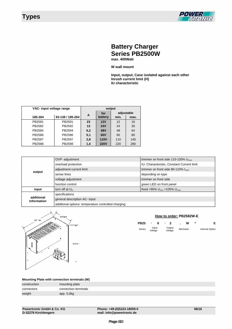
Types
Powertronic GmbH & Co. KG Phone: +49-(0)5223-18059-0 06/16 D-32278 Kirchlengern mail: [email protected]
Battery Charger Series PB2500W max. 400Watt W wall mount Input, output, Case isolated against each other Inrush current limit (H) IU characteristic
VAC- input voltage range output
A
for battery
adjustable 185-264 93-138 / 185-264 min. max.
PB2581 PB2591 23 12V 12 16 PB2582 PB2592 13 24V 24 30
PB2584 PB2594 6,2 48V 48 64
PB2586 PB2596 5,1 60V 60 80
PB2587 PB2597 2,8 110V 110 145
PB2588 PB2598 1,4 220V 220 280
output
OVP- adjustment trimmer on front side 110-130% Unom
overload protection IU- Characteristic, Constant Current limit
adjustment current limit trimmer on front side 80-110% Inom
sense lines depending on type
voltage adjustment trimmer on front side
function control green LED on front panel
input turn off at Uin fixed <95% Umin >105% Umax
additional Information
specifications
general description AC- input
additional options: temperature controlled charging
Mounting Plate with connection terminals (W)
construction mounting plate
connectors connection terminals
weight app. 5,0kg
How to order: PB2582W-E
PB25 . 8 . 2 . W - E
Series Input
voltage Output
voltage Mechanic Internal Option
Page 82Page 110
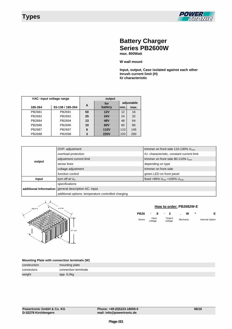
Types
Powertronic GmbH & Co. KG Phone: +49-(0)5223-18059-0 06/16 D-32278 Kirchlengern mail: [email protected]
Battery Charger Series PB2600W max. 800Watt W wall mount Input, output, Case isolated against each other Inrush current limit (H) IU characteristic
VAC- input voltage range output
A
for battery
adjustable
185-264 93-138 / 185-264 min. max.
PB2681 PB2691 50 12V 12 16 PB2682 PB2692 25 24V 24 32
PB2684 PB2694 13 48V 48 64
PB2686 PB2696 10 60V 60 80
PB2687 PB2697 6 110V 110 145
PB2688 PB2698 3 220V 220 290
output
OVP- adjustment trimmer on front side 110-130% Unom
overload protection IU- characteristic, constant current limit
adjustment current limit trimmer on front side 80-110% Inom
sense lines depending on type
voltage adjustment trimmer on front side
function control green LED on front panel
input turn off at Uin fixed <95% Umin >105% Umax
additional Information
specifications
general description AC- input
additional options: temperature controlled charging
Mounting Plate with connection terminals (W)
construction mounting plate
connectors connection terminals
weight app. 6,0kg
How to order: PB2682W-E
PB26 . 8 . 2 . W - E
Series Input
voltage Output
voltage Mechanic Internal Option
Page 83Page 111
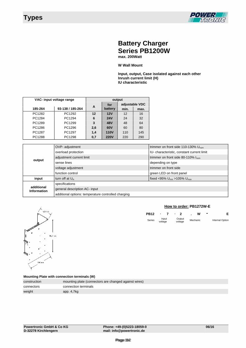
Types
Powertronic GmbH & Co KG Phone: +49-(0)5223-18059-0 06/16 D-32278 Kirchlengern mail: [email protected]
Battery Charger Series PB1200W max. 200Watt W Wall Mount Input, output, Case isolated against each other Inrush current limit (H) IU characteristic
VAC- input voltage range output
A
for battery
adjustable VDC 185-264 93-138 / 185-264 min. max.
PC1282 PC1292 12 12V 12 16 PC1284 PC1294 6 24V 24 32
PC1289 PC1299 3 48V 48 64
PC1286 PC1296 2,6 60V 60 80
PC1287 PC1297 1,4 110V 110 145
PC1288 PC1298 0,7 220V 220 290
output
OVP- adjustment trimmer on front side 110-130% Unom
overload protection IU- characteristic, constant current limit
adjustment current limit trimmer on front side 80-110% Inom
sense lines depending on type
voltage adjustment trimmer on front side
function control green LED on front panel
input turn off at Uin fixed <95% Umin >105% Umax
additional Information
specifications
general description AC- input
additional options: temperature controlled charging
Mounting Plate with connection terminals (W)
construction mounting plate (connectors are changed against wires)
connectors connection terminals
weight app. 4,7kg
How to order: PB1272W-E
PB12 . 7 . 2 . W - E
Series Input
voltage Output
voltage Mechanic Internal Option
Page 84Page 112
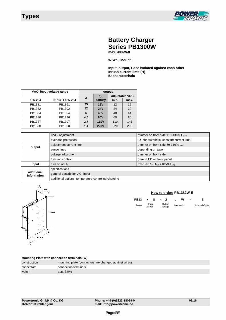
Types
Powertronic GmbH & Co. KG Phone: +49-(0)5223-18059-0 06/16 D-32278 Kirchlengern mail: [email protected]
Battery Charger Series PB1300W max. 400Watt W Wall Mount Input, output, Case isolated against each other Inrush current limit (H) IU characteristic
VAC- input voltage range output
A
for battery
adjustable VDC 185-264 93-138 / 185-264 min. max.
PB1381 PB1391 25 12V 12 16 PB1382 PB1392 12 24V 24 32
PB1384 PB1394 6 48V 48 64
PB1386 PB1396 4,5 60V 60 80
PB1387 PB1397 2,7 110V 110 145
PB1388 PB1398 1,4 220V 220 290
output
OVP- adjustment trimmer on front side 110-130% Unom
overload protection IU- characteristic, constant current limit
adjustment current limit trimmer on front side 80-110% Inom
sense lines depending on type
voltage adjustment trimmer on front side
function control green LED on front panel
input turn off at Uin fixed <95% Umin >105% Umax
additional Information
specifications
general description AC- input
additional options: temperature controlled charging
Mounting Plate with connection terminals (W)
construction mounting plate (connectors are changed against wires)
connectors connection terminals
weight app. 5,0kg
How to order: PB1382W-E
PB13 . 8 . 2 . W - E
Series Input
voltage Output
voltage Mechanic Internal Option
Page 85Page 113
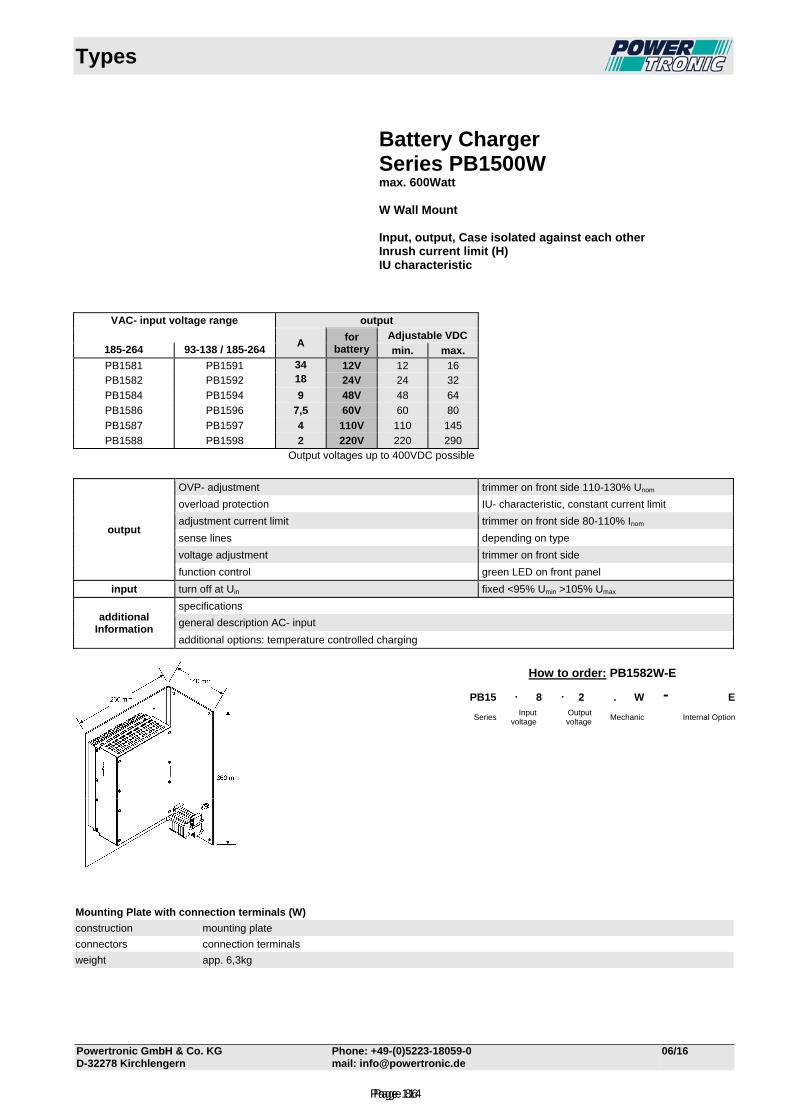
Types
Powertronic GmbH & Co. KG Phone: +49-(0)5223-18059-0 06/16 D-32278 Kirchlengern mail: [email protected]
Battery Charger Series PB1500W max. 600Watt W Wall Mount Input, output, Case isolated against each other Inrush current limit (H) IU characteristic
VAC- input voltage range output
A
for battery
Adjustable VDC 185-264 93-138 / 185-264 min. max.
PB1581 PB1591 34 12V 12 16 PB1582 PB1592 18 24V 24 32
PB1584 PB1594 9 48V 48 64
PB1586 PB1596 7,5 60V 60 80
PB1587 PB1597 4 110V 110 145
PB1588 PB1598 2 220V 220 290 Output voltages up to 400VDC possible
output
OVP- adjustment trimmer on front side 110-130% Unom
overload protection IU- characteristic, constant current limit
adjustment current limit trimmer on front side 80-110% Inom
sense lines depending on type
voltage adjustment trimmer on front side
function control green LED on front panel
input turn off at Uin fixed <95% Umin >105% Umax
additional Information
specifications
general description AC- input
additional options: temperature controlled charging
Mounting Plate with connection terminals (W)
construction mounting plate
connectors connection terminals
weight app. 6,3kg
How to order: PB1582W-E
PB15 . 8 . 2 . W - E
Series Input
voltage Output
voltage Mechanic Internal Option
Page 86Page 114
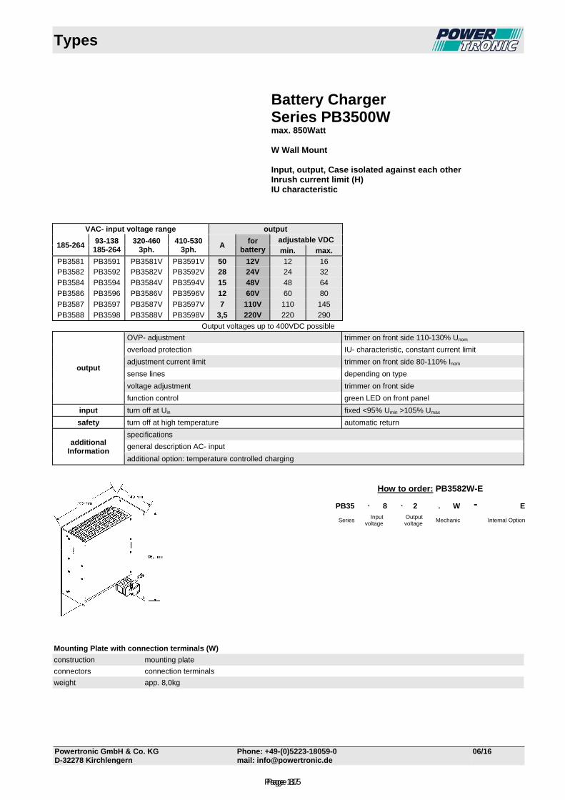
Types
Powertronic GmbH & Co. KG Phone: +49-(0)5223-18059-0 06/16 D-32278 Kirchlengern mail: [email protected]
Battery Charger Series PB3500W max. 850Watt W Wall Mount Input, output, Case isolated against each other Inrush current limit (H) IU characteristic
VAC- input voltage range output
185-264
93-138 185-264
320-460 3ph.
410-530 3ph.
A for
batteryadjustable VDC
min. max.
PB3581 PB3591 PB3581V PB3591V 50 12V 12 16 PB3582 PB3592 PB3582V PB3592V 28 24V 24 32
PB3584 PB3594 PB3584V PB3594V 15 48V 48 64
PB3586 PB3596 PB3586V PB3596V 12 60V 60 80
PB3587 PB3597 PB3587V PB3597V 7 110V 110 145
PB3588 PB3598 PB3588V PB3598V 3,5 220V 220 290
Output voltages up to 400VDC possible
output
OVP- adjustment trimmer on front side 110-130% Unom
overload protection IU- characteristic, constant current limit
adjustment current limit trimmer on front side 80-110% Inom
sense lines depending on type
voltage adjustment trimmer on front side
function control green LED on front panel
input turn off at Uin fixed <95% Umin >105% Umax
safety turn off at high temperature automatic return
additional Information
specifications
general description AC- input
additional option: temperature controlled charging
Mounting Plate with connection terminals (W)
construction mounting plate
connectors connection terminals
weight app. 8,0kg
How to order: PB3582W-E
PB35 . 8 . 2 . W - E
Series Input
voltage Output
voltage Mechanic Internal Option
Page 87Page 115
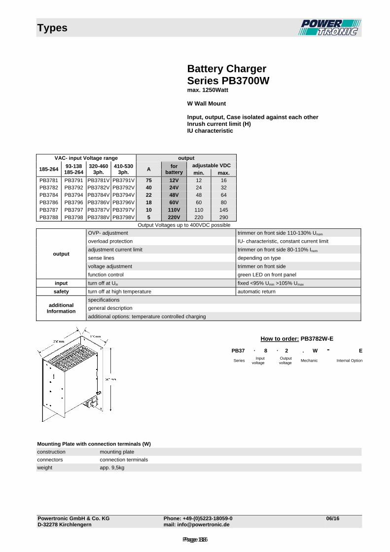
Types
Powertronic GmbH & Co. KG Phone: +49-(0)5223-18059-0 06/16 D-32278 Kirchlengern mail: [email protected]
Battery Charger Series PB3700W max. 1250Watt W Wall Mount Input, output, Case isolated against each other Inrush current limit (H) IU characteristic
VAC- input Voltage range output
185-264
93-138 185-264
320-460 3ph.
410-530 3ph.
A for
battery adjustable VDC
min. max.
PB3781 PB3791 PB3781V PB3791V 75 12V 12 16 PB3782 PB3792 PB3782V PB3792V 40 24V 24 32
PB3784 PB3794 PB3784V PB3794V 22 48V 48 64
PB3786 PB3796 PB3786V PB3796V 18 60V 60 80
PB3787 PB3797 PB3787V PB3797V 10 110V 110 145
PB3788 PB3798 PB3788V PB3798V 5 220V 220 290
Output Voltages up to 400VDC possible
output
OVP- adjustment trimmer on front side 110-130% Unom
overload protection IU- characteristic, constant current limit
adjustment current limit trimmer on front side 80-110% Inom
sense lines depending on type
voltage adjustment trimmer on front side
function control green LED on front panel
input turn off at Uin fixed <95% Umin >105% Umax
safety turn off at high temperature automatic return
additional Information
specifications
general description
additional options: temperature controlled charging
Mounting Plate with connection terminals (W)
construction mounting plate
connectors connection terminals
weight app. 9,5kg
How to order: PB3782W-E
PB37 . 8 . 2 . W - E
Series Input
voltage Output
voltage Mechanic Internal Option
Page 88Page 116
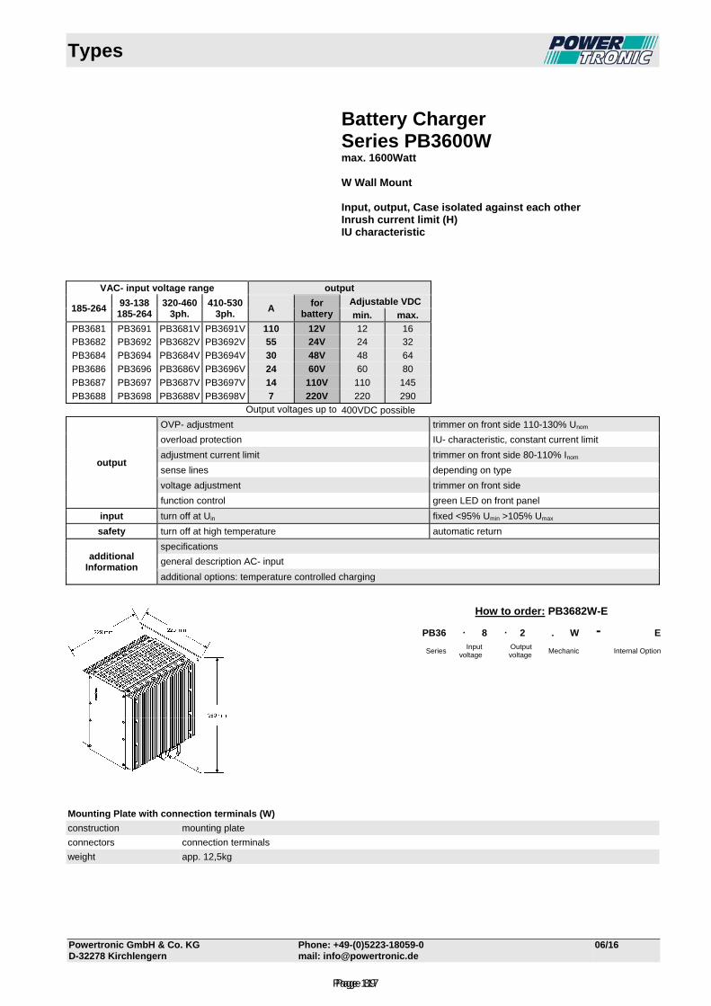
Types
Powertronic GmbH & Co. KG Phone: +49-(0)5223-18059-0 06/16 D-32278 Kirchlengern mail: [email protected]
Battery Charger Series PB3600W max. 1600Watt W Wall Mount Input, output, Case isolated against each other Inrush current limit (H) IU characteristic
VAC- input voltage range output
185-264
93-138 185-264
320-460 3ph.
410-530 3ph.
A for
battery Adjustable VDC
min. max.
PB3681 PB3691 PB3681V PB3691V 110 12V 12 16 PB3682 PB3692 PB3682V PB3692V 55 24V 24 32
PB3684 PB3694 PB3684V PB3694V 30 48V 48 64
PB3686 PB3696 PB3686V PB3696V 24 60V 60 80
PB3687 PB3697 PB3687V PB3697V 14 110V 110 145
PB3688 PB3698 PB3688V PB3698V 7 220V 220 290 Output voltages up to 400VDC possible
output
OVP- adjustment trimmer on front side 110-130% Unom
overload protection IU- characteristic, constant current limit
adjustment current limit trimmer on front side 80-110% Inom
sense lines depending on type
voltage adjustment trimmer on front side
function control green LED on front panel
input turn off at Uin fixed <95% Umin >105% Umax
safety turn off at high temperature automatic return
additional Information
specifications
general description AC- input
additional options: temperature controlled charging
Mounting Plate with connection terminals (W)
construction mounting plate
connectors connection terminals
weight app. 12,5kg
How to order: PB3682W-E
PB36 . 8 . 2 . W - E
Series Input
voltage Output
voltage Mechanic Internal Option
Page 89Page 117
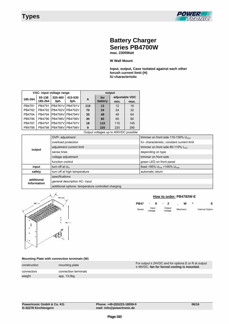
Types
Powertronic GmbH & Co. KG Phone: +49-(0)5223-18059-0 06/16 D-32278 Kirchlengern mail: [email protected]
Battery Charger Series PB4700W max. 2300Watt W Wall Mount Input, output, Case isolated against each other Inrush current limit (H) IU characteristic
VAC- input voltage range output
185-264
93-138 185-264
320-460 3ph.
410-530 3ph.
A for
battery adjustable VDC
min. max.
PB4781 PB4791 PB4781V PB4791V 110 12 12 16 PB4782 PB4792 PB4782V PB4792V 70 24 24 32
PB4784 PB4794 PB4784V PB4794V 35 48 48 64
PB4786 PB4796 PB4786V PB4796V 30 60 60 80
PB4787 PB4797 PB4787V PB4797V 18 110 110 145
PB4788 PB4798 PB4788V PB4798V 9 220 220 290
Output voltages up to 400VDC possible
output
OVP- adjustment trimmer on front side 110-130% Unom
overload protection IU- characteristic, constant current limit
adjustment current limit trimmer on front side 80-110% Inom
sense lines depending on type
voltage adjustment trimmer on front side
function control green LED on front panel
input turn off at Uin fixed <95% Umin >105% Umax
safety turn off at high temperature automatic return
additional Information
specifications
general description AC- input
additional options: temperature controlled charging
Mounting Plate with connection terminals (W)
construction mounting plate For output ≤ 24VDC and for options E or R at output ≤ 48VDC, fan for forced cooling is mounted.
connectors connection terminals
weight app. 13,0kg
How to order: PB4782W-E
PB47 . 8 . 2 . W - E
Series Input
voltage Output
voltage Mechanic Internal Option
Page 90Page 118
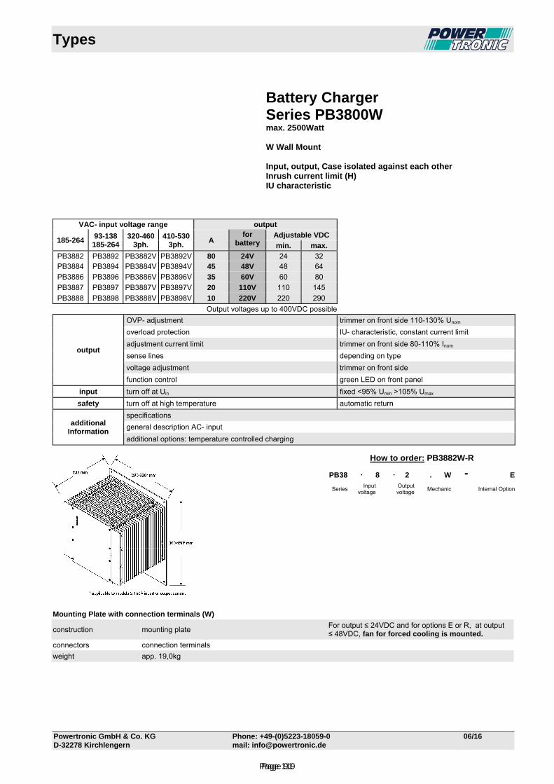
Types
Powertronic GmbH & Co. KG Phone: +49-(0)5223-18059-0 06/16 D-32278 Kirchlengern mail: [email protected]
Battery Charger Series PB3800W max. 2500Watt W Wall Mount Input, output, Case isolated against each other Inrush current limit (H) IU characteristic
VAC- input voltage range output
185-264
93-138 185-264
320-460 3ph.
410-530 3ph.
A for
battery Adjustable VDC
min. max.
PB3882 PB3892 PB3882V PB3892V 80 24V 24 32 PB3884 PB3894 PB3884V PB3894V 45 48V 48 64
PB3886 PB3896 PB3886V PB3896V 35 60V 60 80
PB3887 PB3897 PB3887V PB3897V 20 110V 110 145
PB3888 PB3898 PB3888V PB3898V 10 220V 220 290
Output voltages up to 400VDC possible
output
OVP- adjustment trimmer on front side 110-130% Unom
overload protection IU- characteristic, constant current limit
adjustment current limit trimmer on front side 80-110% Inom
sense lines depending on type
voltage adjustment trimmer on front side
function control green LED on front panel
input turn off at Uin fixed <95% Umin >105% Umax
safety turn off at high temperature automatic return
additional Information
specifications
general description AC- input
additional options: temperature controlled charging
Mounting Plate with connection terminals (W)
construction mounting plate For output ≤ 24VDC and for options E or R, at output ≤ 48VDC, fan for forced cooling is mounted.
connectors connection terminals
weight app. 19,0kg
How to order: PB3882W-R
PB38 . 8 . 2 . W - E
Series Input
voltage Output
voltage Mechanic Internal Option
Page 91Page 119
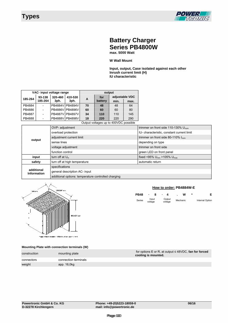
Types
Powertronic GmbH & Co. KG Phone: +49-(0)5223-18059-0 06/16 D-32278 Kirchlengern mail: [email protected]
Battery Charger Series PB4800W max. 5000 Watt W Wall Mount Input, output, Case isolated against each other Inrush current limit (H) IU characteristic
VAC- input voltage range output
185-264
93-138 185-264
320-460 3ph.
410-530 3ph.
A for
battery adjustable VDC
min. max.
PB4884 - PB4884V PB4894V 70 48 48 64 PB4886 - PB4886V PB4896V 60 60 60 80
PB4887 - PB4887V PB4897V 34 110 110 145
PB4888 - PB4888V PB4898V 18 220 220 290 Output voltages up to 400VDC possible
output
OVP- adjustment trimmer on front side 110-130% Unom
overload protection IU- characteristic, constant current limit
adjustment current limit trimmer on front side 80-110% Inom
sense lines depending on type
voltage adjustment trimmer on front side
function control green LED on front panel
input turn off at Uin fixed <95% Umin >105% Umax
safety turn off at high temperature automatic return
additional Information
specifications
general description AC- input
additional options: temperature controlled charging
Mounting Plate with connection terminals (W)
construction mounting plate for options E or R, at output ≤ 48VDC, fan for forced cooling is mounted.
connectors connection terminals
weight app. 16,0kg
How to order: PB4884W-E
PB48 . 8 . 4 . W - E
Series Input
voltage Output
voltage Mechanic Internal Option
Page 92Page 120
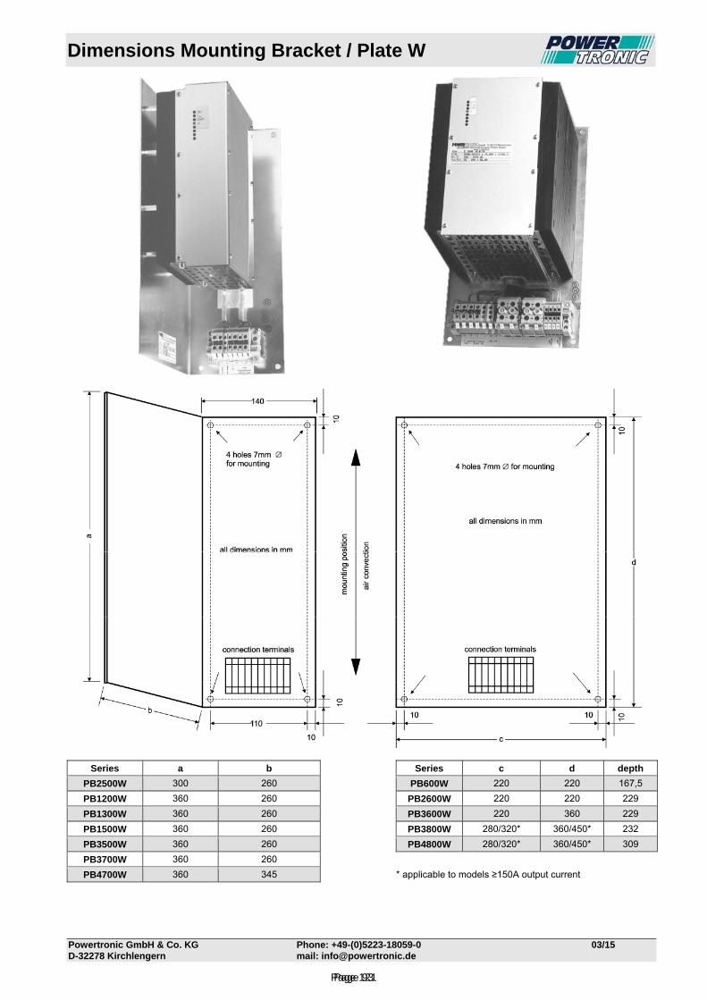
Dimensions Mounting Bracket / Plate W
Powertronic GmbH & Co. KG Phone: +49-(0)5223-18059-0 03/15 D-32278 Kirchlengern mail: [email protected]
Series a b Series c d depth
PB2500W 300 260 PB600W 220 220 167,5
PB1200W 360 260 PB2600W 220 220 229
PB1300W 360 260 PB3600W 220 360 229
PB1500W 360 260 PB3800W 280/320* 360/450* 232
PB3500W 360 260 PB4800W 280/320* 360/450* 309
PB3700W 360 260
PB4700W 360 345 * applicable to models ≥150A output current
Page 93Page 121
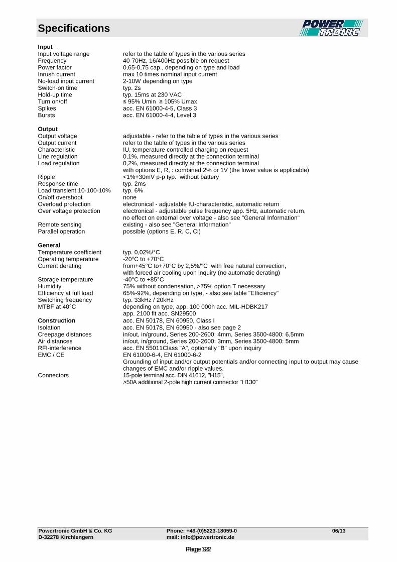
Specifications
Powertronic GmbH & Co. KG Phone: +49-(0)5223-18059-0 06/13 D-32278 Kirchlengern mail: [email protected]
Input Input voltage range refer to the table of types in the various series Frequency 40-70Hz, 16/400Hz possible on request Power factor 0,65-0,75 cap., depending on type and load Inrush current max 10 times nominal input current No-load input current 2-10W depending on type Switch-on time typ. 2s Hold-up time typ. 15ms at 230 VAC Turn on/off ≤ 95% Umin ≥ 105% Umax Spikes acc. EN 61000-4-5, Class 3 Bursts acc. EN 61000-4-4, Level 3 Output Output voltage adjustable - refer to the table of types in the various series Output current refer to the table of types in the various series Characteristic IU, temperature controlled charging on request Line regulation 0,1%, measured directly at the connection terminal Load regulation 0,2%, measured directly at the connection terminal with options E, R, : combined 2% or 1V (the lower value is applicable) Ripple <1%+30mV p-p typ. without battery Response time typ. 2ms Load transient 10-100-10% typ. 6% On/off overshoot none Overload protection electronical - adjustable IU-characteristic, automatic return Over voltage protection electronical - adjustable pulse frequency app. 5Hz, automatic return, no effect on external over voltage - also see "General Information" Remote sensing existing - also see "General Information" Parallel operation possible (options E, R, C, Ci) General Temperature coefficient typ. 0,02%/°C Operating temperature -20°C to +70°C Current derating from+45°C to+70°C by 2,5%/°C with free natural convection, with forced air cooling upon inquiry (no automatic derating) Storage temperature -40°C to +85°C Humidity 75% without condensation, >75% option T necessary Efficiency at full load 65%-92%, depending on type, - also see table "Efficiency" Switching frequency typ. 33kHz / 20kHz MTBF at 40°C depending on type, app. 100 000h acc. MIL-HDBK217 app. 2100 fit acc. SN29500 Construction acc. EN 50178, EN 60950, Class I Isolation acc. EN 50178, EN 60950 - also see page 2 Creepage distances in/out, in/ground, Series 200-2600: 4mm, Series 3500-4800: 6,5mm Air distances in/out, in/ground, Series 200-2600: 3mm, Series 3500-4800: 5mm RFI-interference acc. EN 55011Class "A", optionally "B" upon inquiry EMC / CE EN 61000-6-4, EN 61000-6-2
Grounding of input and/or output potentials and/or connecting input to output may cause changes of EMC and/or ripple values.
Connectors 15-pole terminal acc. DIN 41612, "H15", >50A additional 2-pole high current connector "H130"
Page 94Page 122
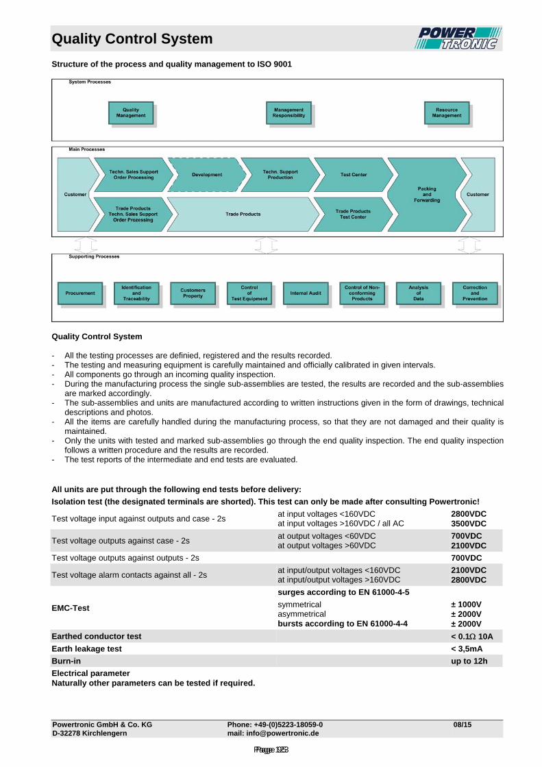
Quality Control System
Powertronic GmbH & Co. KG Phone: +49-(0)5223-18059-0 08/15 D-32278 Kirchlengern mail: [email protected]
Structure of the process and quality management to ISO 9001
Quality Control System - All the testing processes are definied, registered and the results recorded. - The testing and measuring equipment is carefully maintained and officially calibrated in given intervals. - All components go through an incoming quality inspection. - During the manufacturing process the single sub-assemblies are tested, the results are recorded and the sub-assemblies
are marked accordingly. - The sub-assemblies and units are manufactured according to written instructions given in the form of drawings, technical
descriptions and photos. - All the items are carefully handled during the manufacturing process, so that they are not damaged and their quality is
maintained. - Only the units with tested and marked sub-assemblies go through the end quality inspection. The end quality inspection
follows a written procedure and the results are recorded. - The test reports of the intermediate and end tests are evaluated. All units are put through the following end tests before delivery:
Isolation test (the designated terminals are shorted). This test can only be made after consulting Powertronic!
Test voltage input against outputs and case - 2s at input voltages <160VDC at input voltages >160VDC / all AC
2800VDC 3500VDC
Test voltage outputs against case - 2s at output voltages <60VDC at output voltages >60VDC
700VDC 2100VDC
Test voltage outputs against outputs - 2s 700VDC
Test voltage alarm contacts against all - 2s at input/output voltages <160VDC at input/output voltages >160VDC
2100VDC 2800VDC
EMC-Test
surges according to EN 61000-4-5
symmetrical asymmetrical bursts according to EN 61000-4-4
± 1000V ± 2000V ± 2000V
Earthed conductor test < 0.1 10A
Earth leakage test < 3,5mA
Burn-in up to 12h
Electrical parameter Naturally other parameters can be tested if required.
Page 95Page 123
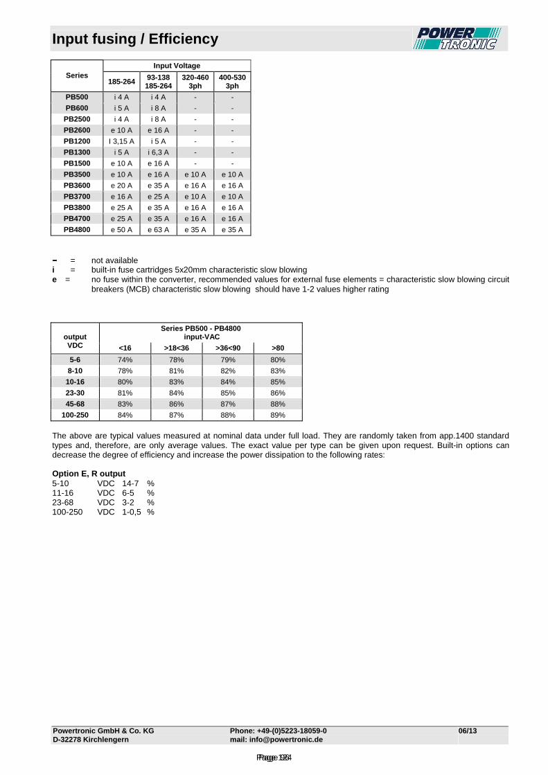
Input fusing / Efficiency
Powertronic GmbH & Co. KG Phone: +49-(0)5223-18059-0 06/13 D-32278 Kirchlengern mail: [email protected]
Input Voltage Series
185-264 93-138 185-264
320-460 3ph
400-530 3ph
PB500 i 4 A i 4 A - -
PB600 i 5 A i 8 A - -
PB2500 i 4 A i 8 A - -
PB2600 e 10 A e 16 A - -
PB1200 I 3,15 A i 5 A - -
PB1300 i 5 A i 6,3 A - -
PB1500 e 10 A e 16 A - -
PB3500 e 10 A e 16 A e 10 A e 10 A
PB3600 e 20 A e 35 A e 16 A e 16 A
PB3700 e 16 A e 25 A e 10 A e 10 A
PB3800 e 25 A e 35 A e 16 A e 16 A
PB4700 e 25 A e 35 A e 16 A e 16 A
PB4800 e 50 A e 63 A e 35 A e 35 A
−−−− = not available i = built-in fuse cartridges 5x20mm characteristic slow blowing e = no fuse within the converter, recommended values for external fuse elements = characteristic slow blowing circuit
breakers (MCB) characteristic slow blowing should have 1-2 values higher rating
Series PB500 - PB4800 input-VAC
output VDC <16 >18<36 >36<90 >80
5-6 74% 78% 79% 80%
8-10 78% 81% 82% 83%
10-16 80% 83% 84% 85%
23-30 81% 84% 85% 86%
45-68 83% 86% 87% 88%
100-250 84% 87% 88% 89%
The above are typical values measured at nominal data under full load. They are randomly taken from app.1400 standard types and, therefore, are only average values. The exact value per type can be given upon request. Built-in options can decrease the degree of efficiency and increase the power dissipation to the following rates: Option E, R output 5-10 VDC 14-7 % 11-16 VDC 6-5 % 23-68 VDC 3-2 % 100-250 VDC 1-0,5 %
Page 96Page 124
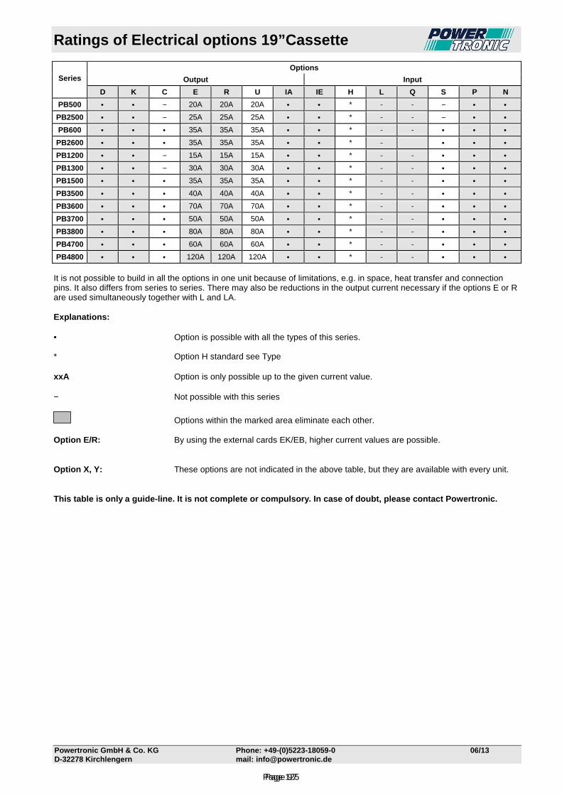
Ratings of Electrical options 19”Cassette
Powertronic GmbH & Co. KG Phone: +49 -(0)5223-18059-0 06/13 D-32278 Kirchlengern mail: [email protected]
Options
Output Input
Series D K C E R U IA IE H L Q S P N
PB500 • • − 20A 20A 20A • • * - - − • •
PB2500 • • − 25A 25A 25A • • * - - − • •
PB600 • • • 35A 35A 35A • • * - - • • •
PB2600 • • • 35A 35A 35A • • * - • • •
PB1200 • • − 15A 15A 15A • • * - - • • •
PB1300 • • − 30A 30A 30A • • * - - • • •
PB1500 • • • 35A 35A 35A • • * - - • • •
PB3500 • • • 40A 40A 40A • • * - - • • •
PB3600 • • • 70A 70A 70A • • * - - • • •
PB3700 • • • 50A 50A 50A • • * - - • • •
PB3800 • • • 80A 80A 80A • • * - - • • •
PB4700 • • • 60A 60A 60A • • * - - • • •
PB4800 • • • 120A 120A 120A • • * - - • • •
It is not possible to build in all the options in one unit because of limitations, e.g. in space, heat transfer and connection pins. It also differs from series to series. There may also be reductions in the output current necessary if the options E or R are used simultaneously together with L and LA. Explanations: • Option is possible with all the types of this series. * Option H standard see Type xxA Option is only possible up to the given current value.
− Not possible with this series
Options within the marked area eliminate each other. Option E/R: By using the external cards EK/EB, higher current values are possible. Option X, Y: These options are not indicated in the above table, but they are available with every unit. This table is only a guide-line. It is not complete or compulsory. In case of doubt, please contact Powertronic.
Page 97Page 125
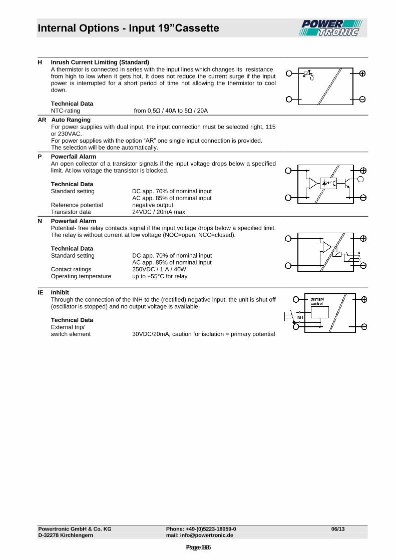
Internal Options - Input 19”Cassette
Powertronic GmbH & Co. KG Phone: +49-(0)5223-18059-0 06/13 D-32278 Kirchlengern mail: [email protected]
H Inrush Current Limiting (Standard)
A thermistor is connected in series with the input lines which changes its resistance from high to low when it gets hot. It does not reduce the current surge if the input power is interrupted for a short period of time not allowing the thermistor to cool down.
Technical Data
NTC-rating from 0,5Ω / 40A to 5Ω / 20A
AR Auto Ranging
For power supplies with dual input, the input connection must be selected right, 115 or 230VAC.
For power supplies with the option “AR” one single input connection is provided. The selection will be done automatically.
P Powerfail Alarm
An open collector of a transistor signals if the input voltage drops below a specified limit. At low voltage the transistor is blocked.
Technical Data
Standard setting DC app. 70% of nominal input AC app. 85% of nominal input Reference potential negative output Transistor data 24VDC / 20mA max.
N Powerfail Alarm
Potential- free relay contacts signal if the input voltage drops below a specified limit. The relay is without current at low voltage (NOC=open, NCC=closed).
Technical Data
Standard setting DC app. 70% of nominal input AC app. 85% of nominal input Contact ratings 250VDC / 1 A / 40W Operating temperature up to +55°C for relay
IE Inhibit
Through the connection of the INH to the (rectified) negative input, the unit is shut off (oscillator is stopped) and no output voltage is available.
Technical Data
External trip/ switch element 30VDC/20mA, caution for isolation = primary potential
Page 98Page 126
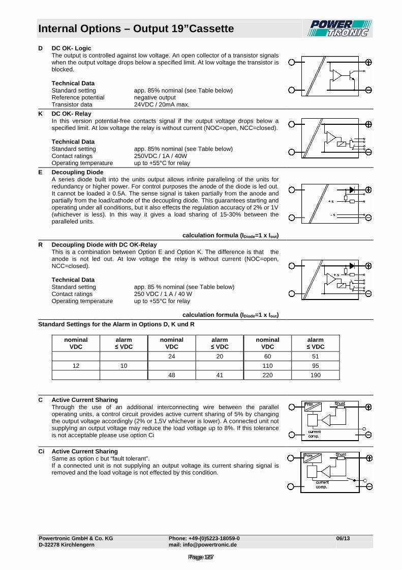
Internal Options – Output 19”Cassette
Powertronic GmbH & Co. KG Phone: +49-(0)5223-18059-0 06/13 D-32278 Kirchlengern mail: [email protected]
D DC OK- Logic The output is controlled against low voltage. An open collector of a transistor signals
when the output voltage drops below a specified limit. At low voltage the transistor is blocked.
Technical Data Standard setting app. 85% nominal (see Table below) Reference potential negative output Transistor data 24VDC / 20mA max.
K DC OK- Relay In this version potential-free contacts signal if the output voltage drops below a
specified limit. At low voltage the relay is without current (NOC=open, NCC=closed). Technical Data Standard setting app. 85% nominal (see Table below) Contact ratings 250VDC / 1A / 40W Operating temperature up to +55°C for relay
E Decoupling Diode A series diode built into the units output allows infinite paralleling of the units for
redundancy or higher power. For control purposes the anode of the diode is led out. It cannot be loaded ≥ 0.5A. The sense signal is taken partially from the anode and partially from the load/cathode of the decoupling diode. This guarantees starting and operating under all conditions, but it also effects the regulation accuracy of 2% or 1V (whichever is less). In this way it gives a load sharing of 15-30% between the paralleled units.
calculation formula (I Diode=1 x Iout )
R Decoupling Diode with DC OK-Relay This is a combination between Option E and Option K. The difference is that the
anode is not led out. At low voltage the relay is without current (NOC=open, NCC=closed).
Technical Data Standard setting app. 85 % nominal (see Table below) Contact ratings 250 VDC / 1 A / 40 W Operating temperature up to +55°C for relay
calculation formula (I Diode=1 x Iout )
Standard Settings for the Alarm in Options D, K und R
nominal VDC
alarm ≤ VDC
nominal VDC
alarm ≤ VDC
nominal VDC
alarm ≤ VDC
24 20 60 51
12 10 110 95
48 41 220 190
C Active Current Sharing Through the use of an additional interconnecting wire between the parallel
operating units, a control circuit provides active current sharing of 5% by changing the output voltage accordingly (2% or 1,5V whichever is lower). A connected unit not supplying an output voltage may reduce the load voltage up to 8%. If this tolerance is not acceptable please use option Ci
Ci Active Current Sharing Same as option c but “fault tolerant”. If a connected unit is not supplying an output voltage its current sharing signal is
removed and the load voltage is not effected by this condition.
Page 99Page 127
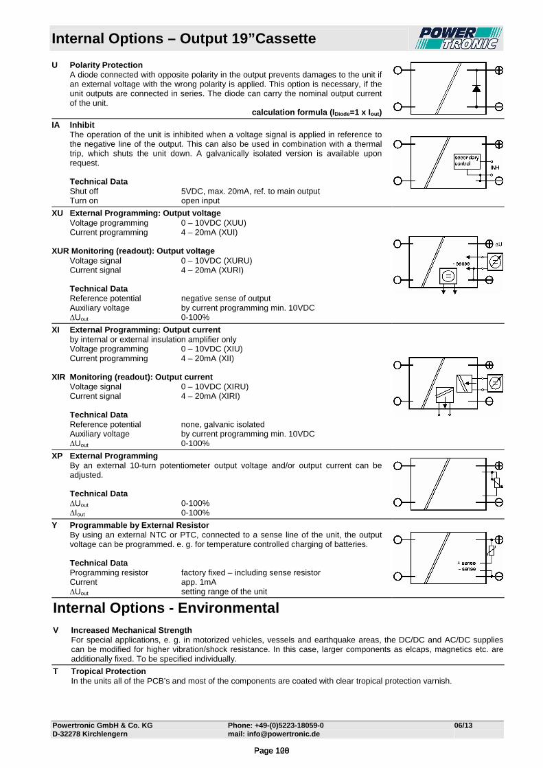
Internal Options – Output 19”Cassette
Powertronic GmbH & Co. KG Phone: +49-(0)5223-18059-0 06/13 D-32278 Kirchlengern mail: [email protected]
U Polarity Protection A diode connected with opposite polarity in the output prevents damages to the unit if
an external voltage with the wrong polarity is applied. This option is necessary, if the unit outputs are connected in series. The diode can carry the nominal output current of the unit.
calculation formula (I Diode=1 x Iout )
IA Inhibit The operation of the unit is inhibited when a voltage signal is applied in reference to
the negative line of the output. This can also be used in combination with a thermal trip, which shuts the unit down. A galvanically isolated version is available upon request.
Technical Data Shut off 5VDC, max. 20mA, ref. to main output Turn on open input
XU External Programming: Output voltage Voltage programming 0 – 10VDC (XUU) Current programming 4 – 20mA (XUI) XUR Monitoring (readout): Output voltage Voltage signal 0 – 10VDC (XURU) Current signal 4 – 20mA (XURI) Technical Data Reference potential negative sense of output Auxiliary voltage by current programming min. 10VDC ∆Uout 0-100%
XI External Programming: Output current by internal or external insulation amplifier only Voltage programming 0 – 10VDC (XIU) Current programming 4 – 20mA (XII) XIR Monitoring (readout): Output current Voltage signal 0 – 10VDC (XIRU) Current signal 4 – 20mA (XIRI) Technical Data Reference potential none, galvanic isolated Auxiliary voltage by current programming min. 10VDC ∆Uout 0-100%
XP External Programming By an external 10-turn potentiometer output voltage and/or output current can be
adjusted. Technical Data ∆Uout 0-100% ∆Iout 0-100%
Y Programmable by External Resistor By using an external NTC or PTC, connected to a sense line of the unit, the output
voltage can be programmed. e. g. for temperature controlled charging of batteries. Technical Data Programming resistor factory fixed – including sense resistor Current app. 1mA ∆Uout setting range of the unit
Internal Options - Environmental V Increased Mechanical Strength For special applications, e. g. in motorized vehicles, vessels and earthquake areas, the DC/DC and AC/DC supplies
can be modified for higher vibration/shock resistance. In this case, larger components as elcaps, magnetics etc. are additionally fixed. To be specified individually.
T Tropical Protection In the units all of the PCB’s and most of the components are coated with clear tropical protection varnish.
Page 100Page 128
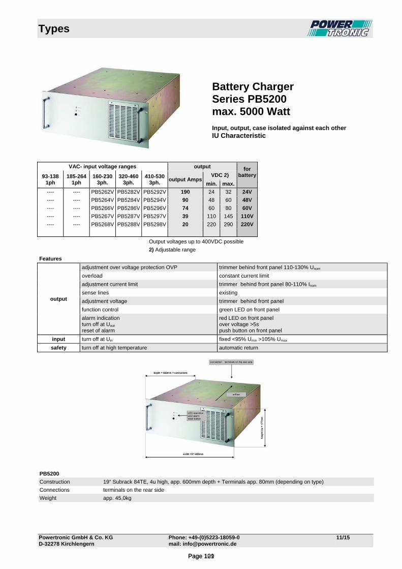
Types
Powertronic GmbH & Co. KG Phone: +49-(0)5223-18059-0 11/15 D-32278 Kirchlengern mail: [email protected]
VAC- input voltage ranges output for battery
93-138
1ph 185-264
1ph 160-230
3ph. 320-460
3ph. 410-530
3ph. output Amps
VDC 2)
min. max.
---- ---- PB5262V PB5282V PB5292V 190 24 32 24V
---- ---- PB5264V PB5284V PB5294V 90 48 60 48V
---- ---- PB5266V PB5286V PB5296V 74 60 80 60V
---- ---- PB5267V PB5287V PB5297V 39 110 145 110V
---- ---- PB5268V PB5288V PB5298V 20 220 290 220V
Output voltages up to 400VDC possible
2) Adjustable range
Features
output
adjustment over voltage protection OVP trimmer behind front panel 110-130% Unom
overload constant current limit
adjustment current limit trimmer behind front panel 80-110% Inom
sense lines existing
adjustment voltage trimmer behind front panel
function control green LED on front panel
alarm indication turn off at Uout
reset of alarm
red LED on front panel over voltage >5s push button on front panel
input turn off at Uin fixed <95% Umin >105% Umax
safety turn off at high temperature automatic return
PB5200
Construction 19“ Subrack 84TE, 4u high, app. 600mm depth + Terminals app. 80mm (depending on type)
Connections terminals on the rear side
Weight app. 45,0kg
Battery Charger Series PB5200 max. 5000 Watt Input, output, case isolated against each other IU Characteristic
Page 101Page 129

Technical Data PB52_2V
Powertronic GmbH & Co. KG Phone: +49-(0)5223-18059-0 06/13 D-32278 Kirchlengern mail: [email protected]
Input Type PB5262V Input voltage 3x 160-230VAC 3-phase Input fuse MCB- 25A, 3pol. slow-characteristic, Type PB5282V Input voltage 3x 320-460VAC 3-phase Input fuse MCB- 20A, 3pol. slow-characteristic, Type PB5292V Input voltage 3x 410-530VAC 3-phase Input fuse MCB- 20A, 3pol. slow-characteristic, Frequency (AC)-input 40-70Hz, Power factor (AC)-input 0,7 capacitive Crest factor (AC)-input <2,5 Inrush current typ. 20-30 times nominal input current No-load input current <25W Switch-on time typ. 1s Hold-up time typ.5ms Turn on/off ≤ 95% Vmin ≥ 105% Vmax Spikes acc. EN 61000-4-5, Class 3 also see "Quality Control" Bursts acc. EN 61000-4-4, Level 3 also see "Quality Control" Output Output voltage for 24VDC-Battery, adjustable 24-32VDC Output current 160ADC Characteristic IU (other characteristics and temperature controlled charging possible on request) Line regulation 0,1%, measured directly at the connection terminal Load regulation 0,2%, measured directly at the connection terminal with options E, R, C: combined 2% or 1V (the lower value is applicable) Ripple < 170mVp-p typ. without battery Response time typ. 10ms Load transient 10-90-10% typ. 6% On/off overshoot none Overload protection electronically Over voltage protection electronically – adjustable switching off after 5-10s →Reset button. no effect on external over voltage Parallel operation possible (options E, R, C, Ci) General Temperature coefficient typ. 0,02%/°C Operating temperature -20°C to +70°C Current derating from+55°C to+70°C by 2,5%/°C (no automatic derating) Cooling internal temperature-controlled fans Over-temperature protection unit switches off Storage temperature -40°C to+85°C Humidity 75% without condensation, (> 75% possible on request) Efficiency at full load >88% Switching frequency typ. 20kHz MTBF at 40°C app. 70 000h acc. MIL-HDBK217 app. 2700 fit acc. SN29500 Construction acc. EN 50178, EN 60950, Class I Isolation acc. EN 50178, EN 60950 Creepage distances in/out, in/ground: 6,5mm Air distances in/out, in/ground: 5mm RFI-interference acc. EN 55011Class "A", optionally "B" upon inquiry EMC / CE EN 61000-6-4, EN 61000-6-2
Grounding of input and/or output potentials and/or connecting input to output may cause changes of EMC and/or ripple values.
Mechanic 19“-subrack 4U high, approx. 602 mm deep + terminals Weight approx. 45kg Connection Terminals at the rear side Options on request „Y“ temperature controlled characteristic 20 to + 45°C „Ci“ current sharing or parallel operation „R“ decoupling diode in the output with monitoring the output voltage, alarm at Uout < 17VDC via relay contact „A“ measuring for output voltage and - current digital 3½ digits, 0,2 % ± 1Digit
Page 102Page 130

Technical Data PB52_4V
Powertronic GmbH & Co. KG Phone: +49-(0)5223-18059-0 06/13 D-32278 Kirchlengern mail: [email protected]
Input Type PB5264V Input voltage 3x 160-230VAC 3-phase Input fuse MCB- 25A, 3pol. slow-characteristic, Type PB5284V Input voltage 3x 320-460VAC 3-phase Input fuse MCB- 20A, 3pol. slow-characteristic, Type PB5294V Input voltage 3x 410-530VAC 3-phase Input fuse MCB- 20A, 3pol. slow-characteristic, Frequency (AC)-input 40-70Hz, Power factor (AC)-input 0,7 capacitive Crest factor (AC)-input <2,5 Inrush current typ. 20-30 times nominal input current No-load input current <25W Switch-on time typ. 1s Hold-up time typ.5ms Turn on/off ≤ 95% Vmin ≥ 105% Vmax Spikes acc. EN 61000-4-5, Class 3 also see "Quality Control" Bursts acc. EN 61000-4-4, Level 3 also see "Quality Control" Output Output voltage for 48VDC-Battery, adjustable 48-64VDC Output current 80ADC Characteristic IU (other characteristics and temperature controlled charging possible on request) Line regulation 0,1%, measured directly at the connection terminal Load regulation 0,2%, measured directly at the connection terminal with options E, R, C: combined 2% or 1V (the lower value is applicable) Ripple < 170mVp-p typ. without battery Response time typ. 10ms Load transient 10-90-10% typ. 6% On/off overshoot none Overload protection electronically Over voltage protection electronically – adjustable switching off after 5-10s →Reset button. no effect on external over voltage Parallel operation possible (options E, R, C, Ci) General Temperature coefficient typ. 0,02%/°C Operating temperature -20°C to +70°C Current derating from+55°C to+70°C by 2,5%/°C (no automatic derating) Cooling internal temperature-controlled fans Over-temperature protection unit switches off Storage temperature -40°C to+85°C Humidity 75% without condensation, (> 75% possible on request) Efficiency at full load >88% Switching frequency typ. 20kHz MTBF at 40°C app. 70 000h acc. MIL-HDBK217 app. 2700 fit acc. SN29500 Construction acc. EN 50178, EN 60950, Class I Isolation acc. EN 50178, EN 60950 Creepage distances in/out, in/ground: 6,5mm Air distances in/out, in/ground: 5mm RFI-interference acc. EN 55011Class "A", optionally "B" upon inquiry EMC / CE EN 61000-6-4, EN 61000-6-2
Grounding of input and/or output potentials and/or connecting input to output may cause changes of EMC and/or ripple values.
Mechanic 19“-subrack 4U high, approx. 602 mm deep + terminals Weight approx. 45kg Connection Terminals at the rear side Options on request „Y“ temperature controlled characteristic 20 to + 45°C „Ci“ current sharing or parallel operation „R“ decoupling diode in the output with monitoring the output voltage, alarm at Uout < 34VDC via relay contact „A“ measuring for output voltage and - current digital 3½ digits, 0,2 % ± 1Digit
Page 103Page 131

Technical Data PB52_6V
Powertronic GmbH & Co. KG Phone: +49-(0)5223-18059-0 06/13 D-32278 Kirchlengern mail: [email protected]
Input Type PB5266V Input voltage 3x 160-230VAC 3-phase Input fuse MCB- 25A, 3pol. slow-characteristic, Type PB5286V Input voltage 3x 320-460VAC 3-phase Input fuse MCB- 20A, 3pol. slow-characteristic, Type PB5296V Input voltage 3x 410-530VAC 3-phase Input fuse MCB- 20A, 3pol. slow-characteristic, Frequency (AC)-input 40-70Hz, Power factor (AC)-input 0,7 capacitive Crest factor (AC)-input <2,5 Inrush current typ. 20-30 times nominal input current No-load input current <25W Switch-on time typ. 1s Hold-up time typ.5ms Turn on/off ≤ 95% Vmin ≥ 105% Vmax Spikes acc. EN 61000-4-5, Class 3 also see "Quality Control" Bursts acc. EN 61000-4-4, Level 3 also see "Quality Control" Output Output voltage for 60VDC-Battery, adjustable 60-80VDC Output current 62ADC Characteristic IU (other characteristics and temperature controlled charging possible on request) Line regulation 0,1%, measured directly at the connection terminal Load regulation 0,2%, measured directly at the connection terminal with options E, R, C: combined 2% or 1V (the lower value is applicable) Ripple < 170mVp-p typ. without battery Response time typ. 10ms Load transient 10-90-10% typ. 6% On/off overshoot none Overload protection electronically Over voltage protection electronically – adjustable switching off after 5-10s →Reset button. no effect on external over voltage Parallel operation possible (options E, R, C, Ci) General Temperature coefficient typ. 0,02%/°C Operating temperature -20°C to +70°C Current derating from+55°C to+70°C by 2,5%/°C (no automatic derating) Cooling internal temperature-controlled fans Over-temperature protection unit switches off Storage temperature -40°C to+85°C Humidity 75% without condensation, (> 75% possible on request) Efficiency at full load >88% Switching frequency typ. 20kHz MTBF at 40°C app. 70 000h acc. MIL-HDBK217 app. 2700 fit acc. SN29500 Construction acc. EN 50178, EN 60950, Class I Isolation acc. EN 50178, EN 60950 Creepage distances in/out, in/ground: 6,5mm Air distances in/out, in/ground: 5mm RFI-interference acc. EN 55011Class "A", optionally "B" upon inquiry EMC / CE EN 61000-6-4, EN 61000-6-2
Grounding of input and/or output potentials and/or connecting input to output may cause changes of EMC and/or ripple values.
Mechanic 19“-subrack 4U high, approx. 602 mm deep + terminals Weight approx. 45kg Connection Terminals at the rear side Options on request „Y“ temperature controlled characteristic 20 to + 45°C „Ci“ current sharing or parallel operation „R“ decoupling diode in the output with monitoring the output voltage, alarm at Uout < 42VDC via relay contact „A“ measuring for output voltage and - current digital 3½ digits, 0,2 % ± 1Digit
Page 104Page 132

Technical Data PB52_7V
Powertronic GmbH & Co. KG Phone: +49-(0)5223-18059-0 06/13 D-32278 Kirchlengern mail: [email protected]
Input Type PB5267V Input voltage 3x 160-230VAC 3-phase Input fuse MCB- 25A, 3pol. slow-characteristic, Type PB5287V Input voltage 3x 320-460VAC 3-phase Input fuse MCB- 20A, 3pol. slow-characteristic, Type PB5297V Input voltage 3x 410-530VAC 3-phase Input fuse MCB- 20A, 3pol. slow-characteristic, Frequency (AC)-input 40-70Hz, Power factor (AC)-input 0,7 capacitive Crest factor (AC)-input <2,5 Inrush current typ. 20-30 times nominal input current No-load input current <25W Switch-on time typ. 1s Hold-up time typ.5ms Turn on/off ≤ 95% Vmin ≥ 105% Vmax Spikes acc. EN 61000-4-5, Class 3 also see "Quality Control" Bursts acc. EN 61000-4-4, Level 3 also see "Quality Control" Output Output voltage for 110VDC-Battery, adjustable 110-145VDC Output current 34ADC Characteristic IU (other characteristics and temperature controlled charging possible on request) Line regulation 0,1%, measured directly at the connection terminal Load regulation 0,2%, measured directly at the connection terminal with options E, R, C: combined 2% or 1V (the lower value is applicable) Ripple < 170mVp-p typ. without battery Response time typ. 10ms Load transient 10-90-10% typ. 6% On/off overshoot none Overload protection electronically Over voltage protection electronically – adjustable switching off after 5-10s →Reset button. no effect on external over voltage Parallel operation possible (options E, R, C, Ci) General Temperature coefficient typ. 0,02%/°C Operating temperature -20°C to +70°C Current derating from+55°C to+70°C by 2,5%/°C (no automatic derating) Cooling internal temperature-controlled fans Over-temperature protection unit switches off Storage temperature -40°C to+85°C Humidity 75% without condensation, (> 75% possible on request) Efficiency at full load >88% Switching frequency typ. 20kHz MTBF at 40°C app. 70 000h acc. MIL-HDBK217 app. 2700 fit acc. SN29500 Construction acc. EN 50178, EN 60950, Class I Isolation acc. EN 50178, EN 60950 Creepage distances in/out, in/ground: 6,5mm Air distances in/out, in/ground: 5mm RFI-interference acc. EN 55011Class "A", optionally "B" upon inquiry EMC / CE EN 61000-6-4, EN 61000-6-2
Grounding of input and/or output potentials and/or connecting input to output may cause changes of EMC and/or ripple values.
Mechanic 19“-subrack 4U high, approx. 602 mm deep + terminals Weight approx. 45kg Connection Terminals at the rear side Options on request „Y“ temperature controlled characteristic 20 to + 45°C „Ci“ current sharing or parallel operation „R“ decoupling diode in the output with monitoring the output voltage, alarm at Uout < 78VDC via relay contact „A“ measuring for output voltage and - current digital 3½ digits, 0,2 % ± 1Digit
Page 105Page 133

Technical Data PB52_8V
Powertronic GmbH & Co. KG Phone: +49-(0)5223-18059-0 06/13 D-32278 Kirchlengern mail: [email protected]
Input Type PB5268V Input voltage 3x 160-230VAC 3-phase Input fuse MCB- 25A, 3pol. slow-characteristic, Type PB5288V Input voltage 3x 320-460VAC 3-phase Input fuse MCB- 20A, 3pol. slow-characteristic, Type PB5298V Input voltage 3x 410-530VAC 3-phase Input fuse MCB- 20A, 3pol. slow-characteristic, Frequency (AC)-input 40-70Hz, Power factor (AC)-input 0,7 capacitive Crest factor (AC)-input <2,5 Inrush current typ. 20-30 times nominal input current No-load input current <25W Switch-on time typ. 1s Hold-up time typ.5ms Turn on/off ≤ 95% Vmin ≥ 105% Vmax Spikes acc. EN 61000-4-5, Class 3 also see "Quality Control" Bursts acc. EN 61000-4-4, Level 3 also see "Quality Control" Output Output voltage for 220VDC-Battery, adjustable 220-290VDC Output current 17ADC Characteristic IU (other characteristics and temperature controlled charging possible on request) Line regulation 0,1%, measured directly at the connection terminal Load regulation 0,2%, measured directly at the connection terminal with options E, R, C: combined 2% or 1V (the lower value is applicable) Ripple < 170mVp-p typ. without battery Response time typ. 10ms Load transient 10-90-10% typ. 6% On/off overshoot none Overload protection electronically Over voltage protection electronically – adjustable switching off after 5-10s →Reset button. no effect on external over voltage Parallel operation possible (options E, R, C, Ci) General Temperature coefficient typ. 0,02%/°C Operating temperature -20°C to +70°C Current derating from+55°C to+70°C by 2,5%/°C (no automatic derating) Cooling internal temperature-controlled fans Over-temperature protection unit switches off Storage temperature -40°C to+85°C Humidity 75% without condensation, (> 75% possible on request) Efficiency at full load >88% Switching frequency typ. 20kHz MTBF at 40°C app. 70 000h acc. MIL-HDBK217 app. 2700 fit acc. SN29500 Construction acc. EN 50178, EN 60950, Class I Isolation acc. EN 50178, EN 60950 Creepage distances in/out, in/ground: 6,5mm Air distances in/out, in/ground: 5mm RFI-interference acc. EN 55011Class "A", optionally "B" upon inquiry EMC / CE EN 61000-6-4, EN 61000-6-2
Grounding of input and/or output potentials and/or connecting input to output may cause changes of EMC and/or ripple values.
Mechanic 19“-subrack 4U high, approx. 602 mm deep + terminals Weight approx. 45kg Connection Terminals at the rear side Options on request „Y“ temperature controlled characteristic 20 to + 45°C „Ci“ current sharing or parallel operation „R“ decoupling diode in the output with monitoring the output voltage, alarm at Uout < 160VDC via relay contact „A“ measuring for output voltage and - current digital 3½ digits, 0,2 % ± 1Digit
Page 106Page 134
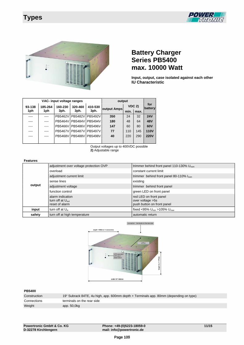
Types
Powertronic GmbH & Co. KG Phone: +49-(0)5223-18059-0 11/15 D-32278 Kirchlengern mail: [email protected]
VAC- input voltage ranges output for
battery93-138 1ph
185-264 1ph
160-230 3ph.
320-460 3ph.
410-530 3ph.
output AmpsVDC 2)
min. max.
---- ---- PB5462V PB5482V PB5492V 350 24 32 24V
---- ---- PB5464V PB5484V PB5494V 180 48 64 48V
---- ---- PB5466V PB5486V PB5496V 147 60 80 60V
---- ---- PB5467V PB5487V PB5497V 77 110 145 110V
---- ---- PB5468V PB5488V PB5498V 40 220 290 220V
Output voltages up to 400VDC possible 2) Adjustable range
Features
output
adjustment over voltage protection OVP trimmer behind front panel 110-130% Unom
overload constant current limit
adjustment current limit trimmer behind front panel 80-110% Inom
sense lines existing
adjustment voltage trimmer behind front panel
function control green LED on front panel
alarm indication turn off at Uout
reset of alarm
red LED on front panel over voltage >5s push button on front panel
input turn off at Uin fixed <95% Umin >105% Umax
safety turn off at high temperature automatic return
PB5400
Construction 19“ Subrack 84TE, 4u high, app. 600mm depth + Terminals app. 80mm (depending on type)
Connections terminals on the rear side
Weight app. 50,0kg
Battery Charger Series PB5400 max. 10000 Watt Input, output, case isolated against each other IU Characteristic
Page 107Page 135

Technical Data PB54_2V
Powertronic GmbH & Co. KG Phone: +49-(0)5223-18059-0 06/13 D-32278 Kirchlengern mail: [email protected]
Input Type PB5462V Input voltage 3x 160-230VAC 3-phase Input fuse MCB- 50A, 3pol. slow-characteristic, Type PB5482V Input voltage 3x 320-460VAC 3-phase Input fuse MCB- 20A, 3pol. slow-characteristic, Type PB5492V Input voltage 3x 410-530VAC 3-phase Input fuse MCB- 20A, 3pol. slow-characteristic, Frequency (AC)-input 40-70Hz, Power factor (AC)-input 0,7 capacitive Crest factor (AC)-input <2,5 Inrush current typ. 20-30 times nominal input current No-load input current <25W Switch-on time typ. 1s Hold-up time typ.5ms Turn on/off ≤ 95% Vmin ≥ 105% Vmax Spikes acc. EN 61000-4-5, Class 3 also see "Quality Control" Bursts acc. EN 61000-4-4, Level 3 also see "Quality Control" Output Output voltage for 24VDC-Battery, adjustable 24-32VDC Output current 320ADC Characteristic IU (other characteristics and temperature controlled charging possible on request) Line regulation 0,1%, measured directly at the connection terminal Load regulation 0,2%, measured directly at the connection terminal with options E, R, C: combined 2% or 1V (the lower value is applicable) Ripple < 170mVp-p typ. without battery Response time typ. 10ms Load transient 10-90-10% typ. 6% On/off overshoot none Overload protection electronically Over voltage protection electronically – adjustable switching off after 5-10s →Reset button. no effect on external over voltage Parallel operation possible (options E, R, C, Ci) General Temperature coefficient typ. 0,02%/°C Operating temperature -20°C to +70°C Current derating from+55°C to+70°C by 2,5%/°C (no automatic derating) Cooling internal temperature-controlled fans Over-temperature protection unit switches off Storage temperature -40°C to+85°C Humidity 75% without condensation, (> 75% possible on request) Efficiency at full load >88% Switching frequency typ. 20kHz MTBF at 40°C app. 70 000h acc. MIL-HDBK217 app. 2700 fit acc. SN29500 Construction acc. EN 50178, EN 60950, Class I Isolation acc. EN 50178, EN 60950 Creepage distances in/out, in/ground: 6,5mm Air distances in/out, in/ground: 5mm RFI-interference acc. EN 55011Class "A", optionally "B" upon inquiry EMC / CE EN 61000-6-4, EN 61000-6-2
Grounding of input and/or output potentials and/or connecting input to output may cause changes of EMC and/or ripple values.
Mechanic 19“-subrack 4U high, approx. 602 mm deep + terminals Weight approx. 50kg Connection Terminals at the rear side Options on request „Y“ temperature controlled characteristic 20 to + 45°C „Ci“ current sharing or parallel operation „R“ decoupling diode in the output with monitoring the output voltage, alarm at Uout < 17VDC via relay contact „A“ measuring for output voltage and - current digital 3½ digits, 0,2 % ± 1Digit
Page 108Page 136

Technical Data PB54_4V
Powertronic GmbH & Co. KG Phone: +49-(0)5223-18059-0 06/13 D-32278 Kirchlengern mail: [email protected]
Input Type PB5464V Input voltage 3x 160-230VAC 3-phase Input fuse MCB- 50A, 3pol. slow-characteristic, Type PB5484V Input voltage 3x 320-460VAC 3-phase Input fuse MCB- 20A, 3pol. slow-characteristic, Type PB5494V Input voltage 3x 410-530VAC 3-phase Input fuse MCB- 20A, 3pol. slow-characteristic, Frequency (AC)-input 40-70Hz, Power factor (AC)-input 0,7 capacitive Crest factor (AC)-input <2,5 Inrush current typ. 20-30 times nominal input current No-load input current <25W Switch-on time typ. 1s Hold-up time typ.5ms Turn on/off ≤ 95% Vmin ≥ 105% Vmax Spikes acc. EN 61000-4-5, Class 3 also see "Quality Control" Bursts acc. EN 61000-4-4, Level 3 also see "Quality Control" Output Output voltage for 48VDC-Battery, adjustable 48-64VDC Output current 160ADC Characteristic IU (other characteristics and temperature controlled charging possible on request) Line regulation 0,1%, measured directly at the connection terminal Load regulation 0,2%, measured directly at the connection terminal with options E, R, C: combined 2% or 1V (the lower value is applicable) Ripple < 170mVp-p typ. without battery Response time typ. 10ms Load transient 10-90-10% typ. 6% On/off overshoot none Overload protection electronically Over voltage protection electronically – adjustable switching off after 5-10s →Reset button. no effect on external over voltage Parallel operation possible (options E, R, C, Ci) General Temperature coefficient typ. 0,02%/°C Operating temperature -20°C to +70°C Current derating from+55°C to+70°C by 2,5%/°C (no automatic derating) Cooling internal temperature-controlled fans Over-temperature protection unit switches off Storage temperature -40°C to+85°C Humidity 75% without condensation, (> 75% possible on request) Efficiency at full load >88% Switching frequency typ. 20kHz MTBF at 40°C app. 70 000h acc. MIL-HDBK217 app. 2700 fit acc. SN29500 Construction acc. EN 50178, EN 60950, Class I Isolation acc. EN 50178, EN 60950 Creepage distances in/out, in/ground: 6,5mm Air distances in/out, in/ground: 5mm RFI-interference acc. EN 55011Class "A", optionally "B" upon inquiry EMC / CE EN 61000-6-4, EN 61000-6-2
Grounding of input and/or output potentials and/or connecting input to output may cause changes of EMC and/or ripple values.
Mechanic 19“-subrack 4U high, approx. 602 mm deep + terminals Weight approx. 50kg Connection Terminals at the rear side Options on request „Y“ temperature controlled characteristic 20 to + 45°C „Ci“ current sharing or parallel operation „R“ decoupling diode in the output with monitoring the output voltage, alarm at Uout < 34VDC via relay contact „A“ measuring for output voltage and - current digital 3½ digits, 0,2 % ± 1Digit
Page 109Page 137

Technical Data PB54_6V
Powertronic GmbH & Co. KG Phone: +49-(0)5223-18059-0 06/13 D-32278 Kirchlengern mail: [email protected]
Input Type PB5466V Input voltage 3x 160-230VAC 3-phase Input fuse MCB- 50A, 3pol. slow-characteristic, Type PB5486V Input voltage 3x 320-460VAC 3-phase Input fuse MCB- 20A, 3pol. slow-characteristic, Type PB5496V Input voltage 3x 410-530VAC 3-phase Input fuse MCB- 20A, 3pol. slow-characteristic, Frequency (AC)-input 40-70Hz, Power factor (AC)-input 0,7 capacitive Crest factor (AC)-input <2,5 Inrush current typ. 20-30 times nominal input current No-load input current <25W Switch-on time typ. 1s Hold-up time typ.5ms Turn on/off ≤ 95% Vmin ≥ 105% Vmax Spikes acc. EN 61000-4-5, Class 3 also see "Quality Control" Bursts acc. EN 61000-4-4, Level 3 also see "Quality Control" Output Output voltage for 60VDC-Battery, adjustable 60-80VDC Output current 130ADC Characteristic IU (other characteristics and temperature controlled charging possible on request) Line regulation 0,1%, measured directly at the connection terminal Load regulation 0,2%, measured directly at the connection terminal with options E, R, C: combined 2% or 1V (the lower value is applicable) Ripple < 170mVp-p typ. without battery Response time typ. 10ms Load transient 10-90-10% typ. 6% On/off overshoot none Overload protection electronically Over voltage protection electronically – adjustable switching off after 5-10s →Reset button. no effect on external over voltage Parallel operation possible (options E, R, C, Ci) General Temperature coefficient typ. 0,02%/°C Operating temperature -20°C to +70°C Current derating from+55°C to+70°C by 2,5%/°C (no automatic derating) Cooling internal temperature-controlled fans Over-temperature protection unit switches off Storage temperature -40°C to+85°C Humidity 75% without condensation, (> 75% possible on request) Efficiency at full load >88% Switching frequency typ. 20kHz MTBF at 40°C app. 70 000h acc. MIL-HDBK217 app. 2700 fit acc. SN29500 Construction acc. EN 50178, EN 60950, Class I Isolation acc. EN 50178, EN 60950 Creepage distances in/out, in/ground: 6,5mm Air distances in/out, in/ground: 5mm RFI-interference acc. EN 55011Class "A", optionally "B" upon inquiry EMC / CE EN 61000-6-4, EN 61000-6-2
Grounding of input and/or output potentials and/or connecting input to output may cause changes of EMC and/or ripple values.
Mechanic 19“-subrack 4U high, approx. 602 mm deep + terminals Weight approx. 50kg Connection Terminals at the rear side Options on request „Y“ temperature controlled characteristic 20 to + 45°C „Ci“ current sharing or parallel operation „R“ decoupling diode in the output with monitoring the output voltage, alarm at Uout < 42VDC via relay contact „A“ measuring for output voltage and - current digital 3½ digits, 0,2 % ± 1Digit
Page 110Page 138
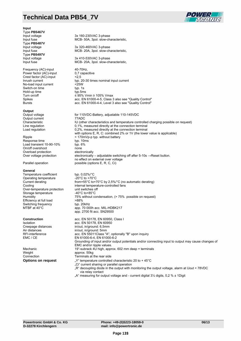
Technical Data PB54_7V
Powertronic GmbH & Co. KG Phone: +49-(0)5223-18059-0 06/13 D-32278 Kirchlengern mail: [email protected]
Input Type PB5467V Input voltage 3x 160-230VAC 3-phase Input fuse MCB- 50A, 3pol. slow-characteristic, Type PB5487V Input voltage 3x 320-460VAC 3-phase Input fuse MCB- 20A, 3pol. slow-characteristic, Type PB5497V Input voltage 3x 410-530VAC 3-phase Input fuse MCB- 20A, 3pol. slow-characteristic, Frequency (AC)-input 40-70Hz, Power factor (AC)-input 0,7 capacitive Crest factor (AC)-input <2,5 Inrush current typ. 20-30 times nominal input current No-load input current <25W Switch-on time typ. 1s Hold-up time typ.5ms Turn on/off ≤ 95% Vmin ≥ 105% Vmax Spikes acc. EN 61000-4-5, Class 3 also see "Quality Control" Bursts acc. EN 61000-4-4, Level 3 also see "Quality Control" Output Output voltage for 110VDC-Battery, adjustable 110-145VDC Output current 77ADC Characteristic IU (other characteristics and temperature controlled charging possible on request) Line regulation 0,1%, measured directly at the connection terminal Load regulation 0,2%, measured directly at the connection terminal with options E, R, C: combined 2% or 1V (the lower value is applicable) Ripple < 170mVp-p typ. without battery Response time typ. 10ms Load transient 10-90-10% typ. 6% On/off overshoot none Overload protection electronically Over voltage protection electronically – adjustable switching off after 5-10s →Reset button. no effect on external over voltage Parallel operation possible (options E, R, C, Ci) General Temperature coefficient typ. 0,02%/°C Operating temperature -20°C to +70°C Current derating from+55°C to+70°C by 2,5%/°C (no automatic derating) Cooling internal temperature-controlled fans Over-temperature protection unit switches off Storage temperature -40°C to+85°C Humidity 75% without condensation, (> 75% possible on request) Efficiency at full load >88% Switching frequency typ. 20kHz MTBF at 40°C app. 70 000h acc. MIL-HDBK217 app. 2700 fit acc. SN29500 Construction acc. EN 50178, EN 60950, Class I Isolation acc. EN 50178, EN 60950 Creepage distances in/out, in/ground: 6,5mm Air distances in/out, in/ground: 5mm RFI-interference acc. EN 55011Class "A", optionally "B" upon inquiry EMC / CE EN 61000-6-4, EN 61000-6-2
Grounding of input and/or output potentials and/or connecting input to output may cause changes of EMC and/or ripple values.
Mechanic 19“-subrack 4U high, approx. 602 mm deep + terminals Weight approx. 50kg Connection Terminals at the rear side Options on request „Y“ temperature controlled characteristic 20 to + 45°C „Ci“ current sharing or parallel operation „R“ decoupling diode in the output with monitoring the output voltage, alarm at Uout < 78VDC via relay contact „A“ measuring for output voltage and - current digital 3½ digits, 0,2 % ± 1Digit
Page 111Page 139

Technical Data PB54_8V
Powertronic GmbH & Co. KG Phone: +49-(0)5223-18059-0 06/13 D-32278 Kirchlengern mail: [email protected]
Input Type PB5468V Input voltage 3x 160-230VAC 3-phase Input fuse MCB- 50A, 3pol. slow-characteristic, Type PB5488V Input voltage 3x 320-460VAC 3-phase Input fuse MCB- 20A, 3pol. slow-characteristic, Type PB5498V Input voltage 3x 410-530VAC 3-phase Input fuse MCB- 20A, 3pol. slow-characteristic, Frequency (AC)-input 40-70Hz, Power factor (AC)-input 0,7 capacitive Crest factor (AC)-input <2,5 Inrush current typ. 20-30 times nominal input current No-load input current <25W Switch-on time typ. 1s Hold-up time typ.5ms Turn on/off ≤ 95% Vmin ≥ 105% Vmax Spikes acc. EN 61000-4-5, Class 3 also see "Quality Control" Bursts acc. EN 61000-4-4, Level 3 also see "Quality Control" Output Output voltage for 220VDC-Battery, adjustable 220-290VDC Output current 35ADC Characteristic IU (other characteristics and temperature controlled charging possible on request) Line regulation 0,1%, measured directly at the connection terminal Load regulation 0,2%, measured directly at the connection terminal with options E, R, C: combined 2% or 1V (the lower value is applicable) Ripple < 170mVp-p typ. without battery Response time typ. 10ms Load transient 10-90-10% typ. 6% On/off overshoot none Overload protection electronically Over voltage protection electronically – adjustable switching off after 5-10s →Reset button. no effect on external over voltage Parallel operation possible (options E, R, C, Ci) General Temperature coefficient typ. 0,02%/°C Operating temperature -20°C to +70°C Current derating from+55°C to+70°C by 2,5%/°C (no automatic derating) Cooling internal temperature-controlled fans Over-temperature protection unit switches off Storage temperature -40°C to+85°C Humidity 75% without condensation, (> 75% possible on request) Efficiency at full load >88% Switching frequency typ. 20kHz MTBF at 40°C app. 70 000h acc. MIL-HDBK217 app. 2700 fit acc. SN29500 Construction acc. EN 50178, EN 60950, Class I Isolation acc. EN 50178, EN 60950 Creepage distances in/out, in/ground: 6,5mm Air distances in/out, in/ground: 5mm RFI-interference acc. EN 55011Class "A", optionally "B" upon inquiry EMC / CE EN 61000-6-4, EN 61000-6-2
Grounding of input and/or output potentials and/or connecting input to output may cause changes of EMC and/or ripple values.
Mechanic 19“-subrack 4U high, approx. 602 mm deep + terminals Weight approx. 50kg Connection Terminals at the rear side Options on request „Y“ temperature controlled characteristic 20 to + 45°C „Ci“ current sharing or parallel operation „R“ decoupling diode in the output with monitoring the output voltage, alarm at Uout < 160VDC via relay contact „A“ measuring for output voltage and - current digital 3½ digits, 0,2 % ± 1Digit
Page 112Page 140
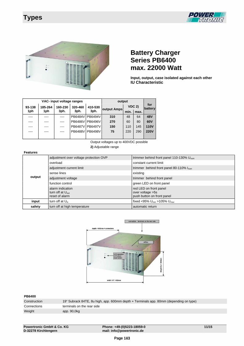
Types
Powertronic GmbH & Co. KG Phone: +49-(0)5223-18059-0 11/15 D-32278 Kirchlengern mail: [email protected]
VAC- input voltage ranges output for
battery93-138 1ph
185-264 1ph
160-230 3ph.
320-460 3ph.
410-530 3ph.
output AmpsVDC 2)
min. max.
---- ---- ---- PB6484V PB6494V 310 48 64 48V
---- ---- ---- PB6486V PB6496V 270 60 80 60V
---- ---- ---- PB6487V PB6497V 150 110 145 110V
---- ---- ---- PB6488V PB6498V 75 220 290 220V
Output voltages up to 400VDC possible
2) Adjustable range
Features
output
adjustment over voltage protection OVP trimmer behind front panel 110-130% Unom
overload constant current limit
adjustment current limit trimmer behind front panel 80-110% Inom
sense lines existing
adjustment voltage trimmer behind front panel
function control green LED on front panel
alarm indication turn off at Uout
reset of alarm
red LED on front panel over voltage >5s push button on front panel
input turn off at Uin fixed <95% Umin >105% Umax
safety turn off at high temperature automatic return
PB6400
Construction 19“ Subrack 84TE, 8u high, app. 600mm depth + Terminals app. 80mm (depending on type)
Connections terminals on the rear side
Weight app. 90,0kg
Battery Charger Series PB6400 max. 22000 Watt Input, output, case isolated against each other IU Characteristic
Page 113Page 141

Technical Data PB64_4V
Powertronic GmbH & Co. KG Phone: +49-(0)5223-18059-0 06/13 D-32278 Kirchlengern mail: [email protected]
Input Type PB6484V Input voltage 3x 320-460VAC 3-phase Input fuse MCB- 35A, 3pol. slow-characteristic, Type PB6494V Input voltage 3x 410-530VAC 3-phase Input fuse MCB- 35A, 3pol. slow-characteristic, Frequency (AC)-input 40-70Hz, Power factor (AC)-input 0,7 capacitive Crest factor (AC)-input <2,5 Inrush current typ. 20-30 times nominal input current No-load input current <25W Switch-on time typ. 1s Hold-up time typ.5ms Turn on/off ≤ 95% Vmin ≥ 105% Vmax Spikes acc. EN 61000-4-5, Class 3 also see "Quality Control" Bursts acc. EN 61000-4-4, Level 3 also see "Quality Control" Output Output voltage for 48VDC-Battery, adjustable 48-64VDC Output current 310ADC Characteristic IU (other characteristics and temperature controlled charging possible on request) Line regulation 0,1%, measured directly at the connection terminal Load regulation 0,2%, measured directly at the connection terminal with options E, R, C: combined 2% or 1V (the lower value is applicable) Ripple < 170mVp-p typ. without battery Response time typ. 10ms Load transient 10-90-10% typ. 6% On/off overshoot none Overload protection electronically Over voltage protection electronically – adjustable switching off after 5-10s →Reset button. no effect on external over voltage Parallel operation possible (options E, R, C, Ci) General Temperature coefficient typ. 0,02%/°C Operating temperature -20°C to +70°C Current derating from+55°C to+70°C by 2,5%/°C (no automatic derating) Cooling internal temperature-controlled fans Over-temperature protection unit switches off Storage temperature -40°C to+85°C Humidity 75% without condensation, (> 75% possible on request) Efficiency at full load >88% Switching frequency typ. 20kHz MTBF at 40°C app. 70 000h acc. MIL-HDBK217 app. 2700 fit acc. SN29500 Construction acc. EN 50178, EN 60950, Class I Isolation acc. EN 50178, EN 60950 Creepage distances in/out, in/ground: 6,5mm Air distances in/out, in/ground: 5mm RFI-interference acc. EN 55011Class "A", optionally "B" upon inquiry EMC / CE EN 61000-6-4, EN 61000-6-2
Grounding of input and/or output potentials and/or connecting input to output may cause changes of EMC and/or ripple values.
Mechanic 19“-subrack 8U high, approx. 602 mm deep + terminals Weight approx. 90kg Connection Terminals at the rear side Options on request „Y“ temperature controlled characteristic 20 to + 45°C „Ci“ current sharing or parallel operation „R“ decoupling diode in the output with monitoring the output voltage, alarm at Uout < 34VDC via relay contact „A“ measuring for output voltage and - current digital 3½ digits, 0,2 % ± 1Digit
Page 114Page 142

Technical Data PB64_6V
Powertronic GmbH & Co. KG Phone: +49-(0)5223-18059-0 06/13 D-32278 Kirchlengern mail: [email protected]
Input Type PB6486V Input voltage 3x 320-460VAC 3-phase Input fuse MCB- 35A, 3pol. slow-characteristic, Type PB6496V Input voltage 3x 410-530VAC 3-phase Input fuse MCB- 35A, 3pol. slow-characteristic, Frequency (AC)-input 40-70Hz, Power factor (AC)-input 0,7 capacitive Crest factor (AC)-input <2,5 Inrush current typ. 20-30 times nominal input current No-load input current <25W Switch-on time typ. 1s Hold-up time typ.5ms Turn on/off ≤ 95% Vmin ≥ 105% Vmax Spikes acc. EN 61000-4-5, Class 3 also see "Quality Control" Bursts acc. EN 61000-4-4, Level 3 also see "Quality Control" Output Output voltage for 60VDC-Battery, adjustable 60-80VDC Output current 270ADC Characteristic IU (other characteristics and temperature controlled charging possible on request) Line regulation 0,1%, measured directly at the connection terminal Load regulation 0,2%, measured directly at the connection terminal with options E, R, C: combined 2% or 1V (the lower value is applicable) Ripple < 170mVp-p typ. without battery Response time typ. 10ms Load transient 10-90-10% typ. 6% On/off overshoot none Overload protection electronically Over voltage protection electronically – adjustable switching off after 5-10s →Reset button. no effect on external over voltage Parallel operation possible (options E, R, C, Ci) General Temperature coefficient typ. 0,02%/°C Operating temperature -20°C to +70°C Current derating from+55°C to+70°C by 2,5%/°C (no automatic derating) Cooling internal temperature-controlled fans Over-temperature protection unit switches off Storage temperature -40°C to+85°C Humidity 75% without condensation, (> 75% possible on request) Efficiency at full load >88% Switching frequency typ. 20kHz MTBF at 40°C app. 70 000h acc. MIL-HDBK217 app. 2700 fit acc. SN29500 Construction acc. EN 50178, EN 60950, Class I Isolation acc. EN 50178, EN 60950 Creepage distances in/out, in/ground: 6,5mm Air distances in/out, in/ground: 5mm RFI-interference acc. EN 55011Class "A", optionally "B" upon inquiry EMC / CE EN 61000-6-4, EN 61000-6-2
Grounding of input and/or output potentials and/or connecting input to output may cause changes of EMC and/or ripple values.
Mechanic 19“-subrack 8U high, approx. 602 mm deep + terminals Weight approx. 90kg Connection Terminals at the rear side Options on request „Y“ temperature controlled characteristic 20 to + 45°C „Ci“ current sharing or parallel operation „R“ decoupling diode in the output with monitoring the output voltage, alarm at Uout < 42VDC via relay contact „A“ measuring for output voltage and - current digital 3½ digits, 0,2 % ± 1Digit
Page 115Page 143
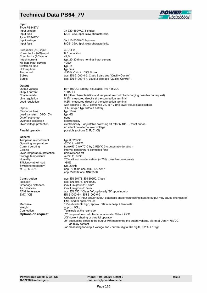
Technical Data PB64_7V
Powertronic GmbH & Co. KG Phone: +49-(0)5223-18059-0 06/13 D-32278 Kirchlengern mail: [email protected]
Input Type PB6487V Input voltage 3x 320-460VAC 3-phase Input fuse MCB- 35A, 3pol. slow-characteristic, Type PB6497V Input voltage 3x 410-530VAC 3-phase Input fuse MCB- 35A, 3pol. slow-characteristic, Frequency (AC)-input 40-70Hz, Power factor (AC)-input 0,7 capacitive Crest factor (AC)-input <2,5 Inrush current typ. 20-30 times nominal input current No-load input current <25W Switch-on time typ. 1s Hold-up time typ.5ms Turn on/off ≤ 95% Vmin ≥ 105% Vmax Spikes acc. EN 61000-4-5, Class 3 also see "Quality Control" Bursts acc. EN 61000-4-4, Level 3 also see "Quality Control" Output Output voltage for 110VDC-Battery, adjustable 110-145VDC Output current 150ADC Characteristic IU (other characteristics and temperature controlled charging possible on request) Line regulation 0,1%, measured directly at the connection terminal Load regulation 0,2%, measured directly at the connection terminal with options E, R, C: combined 2% or 1V (the lower value is applicable) Ripple < 170mVp-p typ. without battery Response time typ. 10ms Load transient 10-90-10% typ. 6% On/off overshoot none Overload protection electronically Over voltage protection electronically – adjustable switching off after 5-10s →Reset button. no effect on external over voltage Parallel operation possible (options E, R, C, Ci) General Temperature coefficient typ. 0,02%/°C Operating temperature -20°C to +70°C Current derating from+55°C to+70°C by 2,5%/°C (no automatic derating) Cooling internal temperature-controlled fans Over-temperature protection unit switches off Storage temperature -40°C to+85°C Humidity 75% without condensation, (> 75% possible on request) Efficiency at full load >88% Switching frequency typ. 20kHz MTBF at 40°C app. 70 000h acc. MIL-HDBK217 app. 2700 fit acc. SN29500 Construction acc. EN 50178, EN 60950, Class I Isolation acc. EN 50178, EN 60950 Creepage distances in/out, in/ground: 6,5mm Air distances in/out, in/ground: 5mm RFI-interference acc. EN 55011Class "A", optionally "B" upon inquiry EMC / CE EN 61000-6-4, EN 61000-6-2
Grounding of input and/or output potentials and/or connecting input to output may cause changes of EMC and/or ripple values.
Mechanic 19“-subrack 8U high, approx. 602 mm deep + terminals Weight approx. 90kg Connection Terminals at the rear side Options on request „Y“ temperature controlled characteristic 20 to + 45°C „Ci“ current sharing or parallel operation „R“ decoupling diode in the output with monitoring the output voltage, alarm at Uout < 78VDC via relay contact „A“ measuring for output voltage and - current digital 3½ digits, 0,2 % ± 1Digit
Page 116Page 144

Technical Data PB64_8V
Powertronic GmbH & Co. KG Phone: +49-(0)5223-18059-0 06/13 D-32278 Kirchlengern mail: [email protected]
Input Type PB6488V Input voltage 3x 320-460VAC 3-phase Input fuse MCB- 35A, 3pol. slow-characteristic, Type PB6498V Input voltage 3x 410-530VAC 3-phase Input fuse MCB- 35A, 3pol. slow-characteristic, Frequency (AC)-input 40-70Hz, Power factor (AC)-input 0,7 capacitive Crest factor (AC)-input <2,5 Inrush current typ. 20-30 times nominal input current No-load input current <25W Switch-on time typ. 1s Hold-up time typ.5ms Turn on/off ≤ 95% Vmin ≥ 105% Vmax Spikes acc. EN 61000-4-5, Class 3 also see "Quality Control" Bursts acc. EN 61000-4-4, Level 3 also see "Quality Control" Output Output voltage for 110VDC-Battery, adjustable 110-145VDC Output current 150ADC Characteristic IU (other characteristics and temperature controlled charging possible on request) Line regulation 0,1%, measured directly at the connection terminal Load regulation 0,2%, measured directly at the connection terminal with options E, R, C: combined 2% or 1V (the lower value is applicable) Ripple < 170mVp-p typ. without battery Response time typ. 10ms Load transient 10-90-10% typ. 6% On/off overshoot none Overload protection electronically Over voltage protection electronically – adjustable switching off after 5-10s →Reset button. no effect on external over voltage Parallel operation possible (options E, R, C, Ci) General Temperature coefficient typ. 0,02%/°C Operating temperature -20°C to +70°C Current derating from+55°C to+70°C by 2,5%/°C (no automatic derating) Cooling internal temperature-controlled fans Over-temperature protection unit switches off Storage temperature -40°C to+85°C Humidity 75% without condensation, (> 75% possible on request) Efficiency at full load >88% Switching frequency typ. 20kHz MTBF at 40°C app. 70 000h acc. MIL-HDBK217 app. 2700 fit acc. SN29500 Construction acc. EN 50178, EN 60950, Class I Isolation acc. EN 50178, EN 60950 Creepage distances in/out, in/ground: 6,5mm Air distances in/out, in/ground: 5mm RFI-interference acc. EN 55011Class "A", optionally "B" upon inquiry EMC / CE EN 61000-6-4, EN 61000-6-2
Grounding of input and/or output potentials and/or connecting input to output may cause changes of EMC and/or ripple values.
Mechanic 19“-subrack 8U high, approx. 602 mm deep + terminals Weight approx. 90kg Connection Terminals at the rear side Options on request „Y“ temperature controlled characteristic 20 to + 45°C „Ci“ current sharing or parallel operation „R“ decoupling diode in the output with monitoring the output voltage, alarm at Uout < 160VDC via relay contact „A“ measuring for output voltage and - current digital 3½ digits, 0,2 % ± 1Digit
Page 117Page 145

Types
Powertronic GmbH & Co. KG Phone: +49-(0)5223-18059-0 11/15 D-32278 Kirchlengern mail: [email protected]
VAC- input voltage ranges output for
battery 160-230 3ph.
320-460 3ph.
410-530 3ph.
size output Amps
VDC 2)
min. max.
PB5662VW PB5682VW PB5692VW O 230 24 32 24V
PB5664VW PB5684VW PB5694VW O 110 48 64 48V
PB5666VW PB5686VW PB5696VW O 88 60 80 60V
PB5667VW PB5687VW PB5697VW O 46 110 145 110V
PB5668VW PB5688VW PB5698VW O 24 220 290 220V
Output voltages up to 400VDC possible 2) Adjustable range
Features
output
adjustment over voltage protection OVP trimmer behind front panel 110-130% Unom
overload constant current limit
adjustment current limit trimmer behind front panel 80-110% Inom
sense lines existing
adjustment voltage trimmer behind front panel
function control green LED on front panel
alarm indication turn off at Uout
reset of alarm
red LED on front panel over voltage >5s push button on front panel
input turn off at Uin fixed <95% Umin >105% Umax
safety turn off at high temperature automatic return
PB5600W
Construction Mounting plate for wall mounting
Connections terminals
Weight depending on type
Battery Charger Series PB5600W max. 6000 Watt W Mounting plate with terminals Input, output, case isolated against each other IU Characteristic
Page 118Page 146

Technical Data PB56_2VW
Powertronic GmbH & Co. KG Phone: +49-(0)5223-18059-0 06/13 D-32278 Kirchlengern mail: [email protected]
Input Type PB5662VW Input voltage 3x 160-230VAC 3-phase Input fuse MCB- 35A, 3pol. slow-characteristic, Type PB5682VW Input voltage 3x 320-460VAC 3-phase Input fuse MCB- 20A, 3pol. slow-characteristic, Type PB5692VW Input voltage 3x 410-530VAC 3-phase Input fuse MCB- 20A, 3pol. slow-characteristic, Frequency (AC)-input 40-70Hz, Power factor (AC)-input 0,7 capacitive Crest factor (AC)-input <2,5 Inrush current typ. 20-30 times nominal input current No-load input current <25W Switch-on time typ. 1s Hold-up time typ.5ms Turn on/off ≤ 95% Vmin ≥ 105% Vmax Spikes acc. EN 61000-4-5, Class 3 also see "Quality Control" Bursts acc. EN 61000-4-4, Level 3 also see "Quality Control" Output Output voltage for 24VDC-Battery, adjustable 24-32VDC Output current 190ADC Characteristic IU (other characteristics and temperature controlled charging possible on request) Line regulation 0,1%, measured directly at the connection terminal Load regulation 0,2%, measured directly at the connection terminal with options E, R, C: combined 2% or 1V (the lower value is applicable) Ripple < 170mVp-p typ. without battery Response time typ. 10ms Load transient 10-90-10% typ. 6% On/off overshoot none Overload protection electronically Over voltage protection electronically – adjustable switching off after 5-10s →Reset button. no effect on external over voltage Parallel operation possible (options E, R, C, Ci) General Temperature coefficient typ. 0,02%/°C Operating temperature -20°C to +70°C Current derating from+55°C to+70°C by 2,5%/°C (no automatic derating) Cooling internal temperature-controlled fans Over-temperature protection unit switches off Storage temperature -40°C to+85°C Humidity 75% without condensation, (> 75% possible on request) Efficiency at full load >88% Switching frequency typ. 20kHz MTBF at 40°C app. 70 000h acc. MIL-HDBK217 app. 2700 fit acc. SN29500 Construction acc. EN 50178, EN 60950, Class I Isolation acc. EN 50178, EN 60950 Creepage distances in/out, in/ground: 6,5mm Air distances in/out, in/ground: 5mm RFI-interference acc. EN 55011Class "A", optionally "B" upon inquiry EMC / CE EN 61000-6-4, EN 61000-6-2
Grounding of input and/or output potentials and/or connecting input to output may cause changes of EMC and/or ripple values.
Mechanic Mounting Plate Dimensions approx. 800mm high x 500mm wide x 310 mm deep Weight approx. 70kg Connection Terminals Options on request „Y“ temperature controlled characteristic 20 to + 45°C „Ci“ current sharing or parallel operation „R“ decoupling diode in the output with monitoring the output voltage, alarm at Uout < 17VDC via relay contact „A“ measuring for output voltage and - current digital 3½ digits, 0,2 % ± 1Digit
Page 119Page 147

Technical Data PB56_4VW
Powertronic GmbH & Co. KG Phone: +49-(0)5223-18059-0 06/13 D-32278 Kirchlengern mail: [email protected]
Input Type PB5664VW Input voltage 3x 160-230VAC 3-phase Input fuse MCB- 35A, 3pol. slow-characteristic, Type PB5684VW Input voltage 3x 320-460VAC 3-phase Input fuse MCB- 20A, 3pol. slow-characteristic, Type PB5694VW Input voltage 3x 410-530VAC 3-phase Input fuse MCB- 20A, 3pol. slow-characteristic, Frequency (AC)-input 40-70Hz, Power factor (AC)-input 0,7 capacitive Crest factor (AC)-input <2,5 Inrush current typ. 20-30 times nominal input current No-load input current <25W Switch-on time typ. 1s Hold-up time typ.5ms Turn on/off ≤ 95% Vmin ≥ 105% Vmax Spikes acc. EN 61000-4-5, Class 3 also see "Quality Control" Bursts acc. EN 61000-4-4, Level 3 also see "Quality Control" Output Output voltage for 48VDC-Battery, adjustable 48-64VDC Output current 95ADC Characteristic IU (other characteristics and temperature controlled charging possible on request) Line regulation 0,1%, measured directly at the connection terminal Load regulation 0,2%, measured directly at the connection terminal with options E, R, C: combined 2% or 1V (the lower value is applicable) Ripple < 170mVp-p typ. without battery Response time typ. 10ms Load transient 10-90-10% typ. 6% On/off overshoot none Overload protection electronically Over voltage protection electronically – adjustable switching off after 5-10s →Reset button. no effect on external over voltage Parallel operation possible (options E, R, C, Ci) General Temperature coefficient typ. 0,02%/°C Operating temperature -20°C to +70°C Current derating from+55°C to+70°C by 2,5%/°C (no automatic derating) Cooling internal temperature-controlled fans Over-temperature protection unit switches off Storage temperature -40°C to+85°C Humidity 75% without condensation, (> 75% possible on request) Efficiency at full load >88% Switching frequency typ. 20kHz MTBF at 40°C app. 70 000h acc. MIL-HDBK217 app. 2700 fit acc. SN29500 Construction acc. EN 50178, EN 60950, Class I Isolation acc. EN 50178, EN 60950 Creepage distances in/out, in/ground: 6,5mm Air distances in/out, in/ground: 5mm RFI-interference acc. EN 55011Class "A", optionally "B" upon inquiry EMC / CE EN 61000-6-4, EN 61000-6-2
Grounding of input and/or output potentials and/or connecting input to output may cause changes of EMC and/or ripple values.
Mechanic Mounting Plate Dimensions approx. 800mm high x 500mm wide x 310 mm deep Weight approx. 70kg Connection Terminals Options on request „Y“ temperature controlled characteristic 20 to + 45°C „Ci“ current sharing or parallel operation „R“ decoupling diode in the output with monitoring the output voltage, alarm at Uout < 34VDC via relay contact „A“ measuring for output voltage and - current digital 3½ digits, 0,2 % ± 1Digit
Page 120Page 148
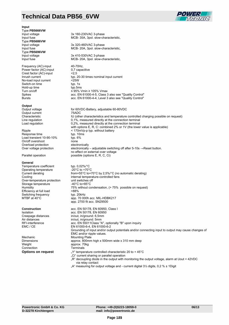
Technical Data PB56_6VW
Powertronic GmbH & Co. KG Phone: +49-(0)5223-18059-0 06/13 D-32278 Kirchlengern mail: [email protected]
Input Type PB5666VW Input voltage 3x 160-230VAC 3-phase Input fuse MCB- 35A, 3pol. slow-characteristic, Type PB5686VW Input voltage 3x 320-460VAC 3-phase Input fuse MCB- 20A, 3pol. slow-characteristic, Type PB5696VW Input voltage 3x 410-530VAC 3-phase Input fuse MCB- 20A, 3pol. slow-characteristic, Frequency (AC)-input 40-70Hz, Power factor (AC)-input 0,7 capacitive Crest factor (AC)-input <2,5 Inrush current typ. 20-30 times nominal input current No-load input current <25W Switch-on time typ. 1s Hold-up time typ.5ms Turn on/off ≤ 95% Vmin ≥ 105% Vmax Spikes acc. EN 61000-4-5, Class 3 also see "Quality Control" Bursts acc. EN 61000-4-4, Level 3 also see "Quality Control" Output Output voltage for 60VDC-Battery, adjustable 60-80VDC Output current 75ADC Characteristic IU (other characteristics and temperature controlled charging possible on request) Line regulation 0,1%, measured directly at the connection terminal Load regulation 0,2%, measured directly at the connection terminal with options E, R, C: combined 2% or 1V (the lower value is applicable) Ripple < 170mVp-p typ. without battery Response time typ. 10ms Load transient 10-90-10% typ. 6% On/off overshoot none Overload protection electronically Over voltage protection electronically – adjustable switching off after 5-10s →Reset button. no effect on external over voltage Parallel operation possible (options E, R, C, Ci) General Temperature coefficient typ. 0,02%/°C Operating temperature -20°C to +70°C Current derating from+55°C to+70°C by 2,5%/°C (no automatic derating) Cooling internal temperature-controlled fans Over-temperature protection unit switches off Storage temperature -40°C to+85°C Humidity 75% without condensation, (> 75% possible on request) Efficiency at full load >88% Switching frequency typ. 20kHz MTBF at 40°C app. 70 000h acc. MIL-HDBK217 app. 2700 fit acc. SN29500 Construction acc. EN 50178, EN 60950, Class I Isolation acc. EN 50178, EN 60950 Creepage distances in/out, in/ground: 6,5mm Air distances in/out, in/ground: 5mm RFI-interference acc. EN 55011Class "A", optionally "B" upon inquiry EMC / CE EN 61000-6-4, EN 61000-6-2
Grounding of input and/or output potentials and/or connecting input to output may cause changes of EMC and/or ripple values.
Mechanic Mounting Plate Dimensions approx. 800mm high x 500mm wide x 310 mm deep Weight approx. 70kg Connection Terminals Options on request „Y“ temperature controlled characteristic 20 to + 45°C „Ci“ current sharing or parallel operation „R“ decoupling diode in the output with monitoring the output voltage, alarm at Uout < 42VDC via relay contact „A“ measuring for output voltage and - current digital 3½ digits, 0,2 % ± 1Digit
Page 121Page 149
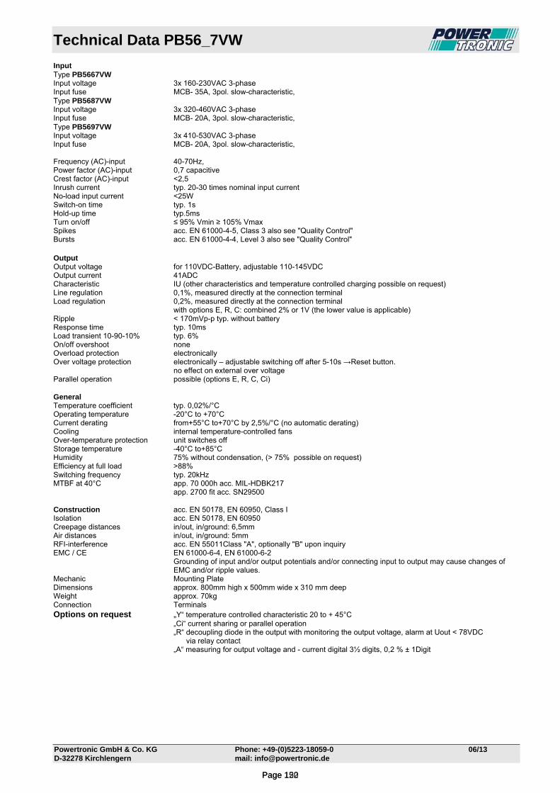
Technical Data PB56_7VW
Powertronic GmbH & Co. KG Phone: +49-(0)5223-18059-0 06/13 D-32278 Kirchlengern mail: [email protected]
Input Type PB5667VW Input voltage 3x 160-230VAC 3-phase Input fuse MCB- 35A, 3pol. slow-characteristic, Type PB5687VW Input voltage 3x 320-460VAC 3-phase Input fuse MCB- 20A, 3pol. slow-characteristic, Type PB5697VW Input voltage 3x 410-530VAC 3-phase Input fuse MCB- 20A, 3pol. slow-characteristic, Frequency (AC)-input 40-70Hz, Power factor (AC)-input 0,7 capacitive Crest factor (AC)-input <2,5 Inrush current typ. 20-30 times nominal input current No-load input current <25W Switch-on time typ. 1s Hold-up time typ.5ms Turn on/off ≤ 95% Vmin ≥ 105% Vmax Spikes acc. EN 61000-4-5, Class 3 also see "Quality Control" Bursts acc. EN 61000-4-4, Level 3 also see "Quality Control" Output Output voltage for 110VDC-Battery, adjustable 110-145VDC Output current 41ADC Characteristic IU (other characteristics and temperature controlled charging possible on request) Line regulation 0,1%, measured directly at the connection terminal Load regulation 0,2%, measured directly at the connection terminal with options E, R, C: combined 2% or 1V (the lower value is applicable) Ripple < 170mVp-p typ. without battery Response time typ. 10ms Load transient 10-90-10% typ. 6% On/off overshoot none Overload protection electronically Over voltage protection electronically – adjustable switching off after 5-10s →Reset button. no effect on external over voltage Parallel operation possible (options E, R, C, Ci) General Temperature coefficient typ. 0,02%/°C Operating temperature -20°C to +70°C Current derating from+55°C to+70°C by 2,5%/°C (no automatic derating) Cooling internal temperature-controlled fans Over-temperature protection unit switches off Storage temperature -40°C to+85°C Humidity 75% without condensation, (> 75% possible on request) Efficiency at full load >88% Switching frequency typ. 20kHz MTBF at 40°C app. 70 000h acc. MIL-HDBK217 app. 2700 fit acc. SN29500 Construction acc. EN 50178, EN 60950, Class I Isolation acc. EN 50178, EN 60950 Creepage distances in/out, in/ground: 6,5mm Air distances in/out, in/ground: 5mm RFI-interference acc. EN 55011Class "A", optionally "B" upon inquiry EMC / CE EN 61000-6-4, EN 61000-6-2
Grounding of input and/or output potentials and/or connecting input to output may cause changes of EMC and/or ripple values.
Mechanic Mounting Plate Dimensions approx. 800mm high x 500mm wide x 310 mm deep Weight approx. 70kg Connection Terminals Options on request „Y“ temperature controlled characteristic 20 to + 45°C „Ci“ current sharing or parallel operation „R“ decoupling diode in the output with monitoring the output voltage, alarm at Uout < 78VDC via relay contact „A“ measuring for output voltage and - current digital 3½ digits, 0,2 % ± 1Digit
Page 122Page 150

Technical Data PB56_8VW
Powertronic GmbH & Co. KG Phone: +49-(0)5223-18059-0 06/13 D-32278 Kirchlengern mail: [email protected]
Input Type PB5668VW Input voltage 3x 160-230VAC 3-phase Input fuse MCB- 35A, 3pol. slow-characteristic, Type PB5688VW Input voltage 3x 320-460VAC 3-phase Input fuse MCB- 20A, 3pol. slow-characteristic, Type PB5698VW Input voltage 3x 410-530VAC 3-phase Input fuse MCB- 20A, 3pol. slow-characteristic, Frequency (AC)-input 40-70Hz, Power factor (AC)-input 0,7 capacitive Crest factor (AC)-input <2,5 Inrush current typ. 20-30 times nominal input current No-load input current <25W Switch-on time typ. 1s Hold-up time typ.5ms Turn on/off ≤ 95% Vmin ≥ 105% Vmax Spikes acc. EN 61000-4-5, Class 3 also see "Quality Control" Bursts acc. EN 61000-4-4, Level 3 also see "Quality Control" Output Output voltage for 220VDC-Battery, adjustable 220-290VDC Output current 21ADC Characteristic IU (other characteristics and temperature controlled charging possible on request) Line regulation 0,1%, measured directly at the connection terminal Load regulation 0,2%, measured directly at the connection terminal with options E, R, C: combined 2% or 1V (the lower value is applicable) Ripple < 170mVp-p typ. without battery Response time typ. 10ms Load transient 10-90-10% typ. 6% On/off overshoot none Overload protection electronically Over voltage protection electronically – adjustable switching off after 5-10s →Reset button. no effect on external over voltage Parallel operation possible (options E, R, C, Ci) General Temperature coefficient typ. 0,02%/°C Operating temperature -20°C to +70°C Current derating from+55°C to+70°C by 2,5%/°C (no automatic derating) Cooling internal temperature-controlled fans Over-temperature protection unit switches off Storage temperature -40°C to+85°C Humidity 75% without condensation, (> 75% possible on request) Efficiency at full load >88% Switching frequency typ. 20kHz MTBF at 40°C app. 70 000h acc. MIL-HDBK217 app. 2700 fit acc. SN29500 Construction acc. EN 50178, EN 60950, Class I Isolation acc. EN 50178, EN 60950 Creepage distances in/out, in/ground: 6,5mm Air distances in/out, in/ground: 5mm RFI-interference acc. EN 55011Class "A", optionally "B" upon inquiry EMC / CE EN 61000-6-4, EN 61000-6-2
Grounding of input and/or output potentials and/or connecting input to output may cause changes of EMC and/or ripple values.
Mechanic Mounting Plate Dimensions approx. 800mm high x 500mm wide x 310 mm deep Weight approx. 70kg Connection Terminals Options on request „Y“ temperature controlled characteristic 20 to + 45°C „Ci“ current sharing or parallel operation „R“ decoupling diode in the output with monitoring the output voltage, alarm at Uout < 160VDC via relay contact „A“ measuring for output voltage and - current digital 3½ digits, 0,2 % ± 1Digit
Page 123Page 151
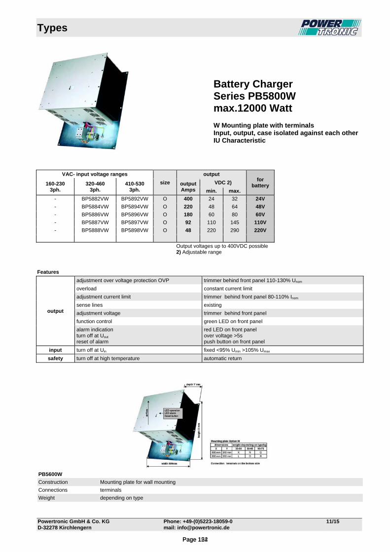
Types
Powertronic GmbH & Co. KG Phone: +49-(0)5223-18059-0 11/15 D-32278 Kirchlengern mail: [email protected]
VAC- input voltage ranges output for
battery 160-230 3ph.
320-460 3ph.
410-530 3ph.
size output Amps
VDC 2)
min. max.
- BP5882VW BP5892VW O 400 24 32 24V
- BP5884VW BP5894VW O 220 48 64 48V
- BP5886VW BP5896VW O 180 60 80 60V
- BP5887VW BP5897VW O 92 110 145 110V
- BP5888VW BP5898VW O 48 220 290 220V
Output voltages up to 400VDC possible 2) Adjustable range
Features
output
adjustment over voltage protection OVP trimmer behind front panel 110-130% Unom
overload constant current limit
adjustment current limit trimmer behind front panel 80-110% Inom
sense lines existing
adjustment voltage trimmer behind front panel
function control green LED on front panel
alarm indication turn off at Uout
reset of alarm
red LED on front panel over voltage >5s push button on front panel
input turn off at Uin fixed <95% Umin >105% Umax
safety turn off at high temperature automatic return
PB5600W
Construction Mounting plate for wall mounting
Connections terminals
Weight depending on type
Battery Charger Series PB5800W max.12000 Watt W Mounting plate with terminals Input, output, case isolated against each other IU Characteristic
Page 124Page 152

Technical Data PB58_4VW
Powertronic GmbH & Co. KG Phone: +49-(0)5223-18059-0 11/15 D-32278 Kirchlengern mail: [email protected]
Input Type PB5884VW Input voltage 3x 320-460VAC 3-phase Input fuse MCB- 20A, 3pol. slow-characteristic, Type PB5894VW Input voltage 3x 410-530VAC 3-phase Input fuse MCB- 20A, 3pol. slow-characteristic, Frequency (AC)-input 40-70Hz, Power factor (AC)-input 0,7 capacitive Crest factor (AC)-input <2,5 Inrush current typ. 20-30 times nominal input current No-load input current <25W Switch-on time typ. 1s Hold-up time typ.5ms Turn on/off ≤ 95% Vmin ≥ 105% Vmax Spikes acc. EN 61000-4-5, Class 3 also see "Quality Control" Bursts acc. EN 61000-4-4, Level 3 also see "Quality Control" Output Output voltage for 48VDC-Battery, adjustable 48-64VDC Output current 190ADC Characteristic IU (other characteristics and temperature controlled charging possible on request) Line regulation 0,1%, measured directly at the connection terminal Load regulation 0,2%, measured directly at the connection terminal with options E, R, C: combined 2% or 1V (the lower value is applicable) Ripple < 170mVp-p typ. without battery Response time typ. 10ms Load transient 10-90-10% typ. 6% On/off overshoot none Overload protection electronically Over voltage protection electronically – adjustable switching off after 5-10s →Reset button. no effect on external over voltage Parallel operation possible (options E, R, C, Ci) General Temperature coefficient typ. 0,02%/°C Operating temperature -20°C to +70°C Current derating from+55°C to+70°C by 2,5%/°C (no automatic derating) Cooling internal temperature-controlled fans Over-temperature protection unit switches off Storage temperature -40°C to+85°C Humidity 75% without condensation, (> 75% possible on request) Efficiency at full load >88% Switching frequency typ. 20kHz MTBF at 40°C app. 70 000h acc. MIL-HDBK217 app. 2700 fit acc. SN29500 Construction acc. EN 50178, EN 60950, Class I Isolation acc. EN 50178, EN 60950 Creepage distances in/out, in/ground: 6,5mm Air distances in/out, in/ground: 5mm RFI-interference acc. EN 55011Class "A", optionally "B" upon inquiry EMC / CE EN 61000-6-4, EN 61000-6-2
Grounding of input and/or output potentials and/or connecting input to output may cause changes of EMC and/or ripple values.
Mechanic Mounting Plate Dimensions approx. 800mm high x 500mm wide x 310 mm deep Weight approx. 70kg Connection Terminals Options on request „Y“ temperature controlled characteristic 20 to + 45°C „Ci“ current sharing or parallel operation „R“ decoupling diode in the output with monitoring the output voltage, alarm at Uout < 34VDC via relay contact „A“ measuring for output voltage and - current digital 3½ digits, 0,2 % ± 1Digit
Page 125Page 153

Technical Data PB58_6VW
Powertronic GmbH & Co. KG Phone: +49-(0)5223-18059-0 06/13 D-32278 Kirchlengern mail: [email protected]
Input Type PB5886VW Input voltage 3x 320-460VAC 3-phase Input fuse MCB- 20A, 3pol. slow-characteristic, Type PB5896VW Input voltage 3x 410-530VAC 3-phase Input fuse MCB- 20A, 3pol. slow-characteristic, Frequency (AC)-input 40-70Hz, Power factor (AC)-input 0,7 capacitive Crest factor (AC)-input <2,5 Inrush current typ. 20-30 times nominal input current No-load input current <25W Switch-on time typ. 1s Hold-up time typ.5ms Turn on/off ≤ 95% Vmin ≥ 105% Vmax Spikes acc. EN 61000-4-5, Class 3 also see "Quality Control" Bursts acc. EN 61000-4-4, Level 3 also see "Quality Control" Output Output voltage for 60VDC-Battery, adjustable 60-80VDC Output current 155ADC Characteristic IU (other characteristics and temperature controlled charging possible on request) Line regulation 0,1%, measured directly at the connection terminal Load regulation 0,2%, measured directly at the connection terminal with options E, R, C: combined 2% or 1V (the lower value is applicable) Ripple < 170mVp-p typ. without battery Response time typ. 10ms Load transient 10-90-10% typ. 6% On/off overshoot none Overload protection electronically Over voltage protection electronically – adjustable switching off after 5-10s →Reset button. no effect on external over voltage Parallel operation possible (options E, R, C, Ci) General Temperature coefficient typ. 0,02%/°C Operating temperature -20°C to +70°C Current derating from+55°C to+70°C by 2,5%/°C (no automatic derating) Cooling internal temperature-controlled fans Over-temperature protection unit switches off Storage temperature -40°C to+85°C Humidity 75% without condensation, (> 75% possible on request) Efficiency at full load >88% Switching frequency typ. 20kHz MTBF at 40°C app. 70 000h acc. MIL-HDBK217 app. 2700 fit acc. SN29500 Construction acc. EN 50178, EN 60950, Class I Isolation acc. EN 50178, EN 60950 Creepage distances in/out, in/ground: 6,5mm Air distances in/out, in/ground: 5mm RFI-interference acc. EN 55011Class "A", optionally "B" upon inquiry EMC / CE EN 61000-6-4, EN 61000-6-2
Grounding of input and/or output potentials and/or connecting input to output may cause changes of EMC and/or ripple values.
Mechanic Mounting Plate Dimensions approx. 800mm high x 500mm wide x 310 mm deep Weight approx. 70kg Connection Terminals Options on request „Y“ temperature controlled characteristic 20 to + 45°C „Ci“ current sharing or parallel operation „R“ decoupling diode in the output with monitoring the output voltage, alarm at Uout < 42VDC via relay contact „A“ measuring for output voltage and - current digital 3½ digits, 0,2 % ± 1Digit
Page 126Page 154
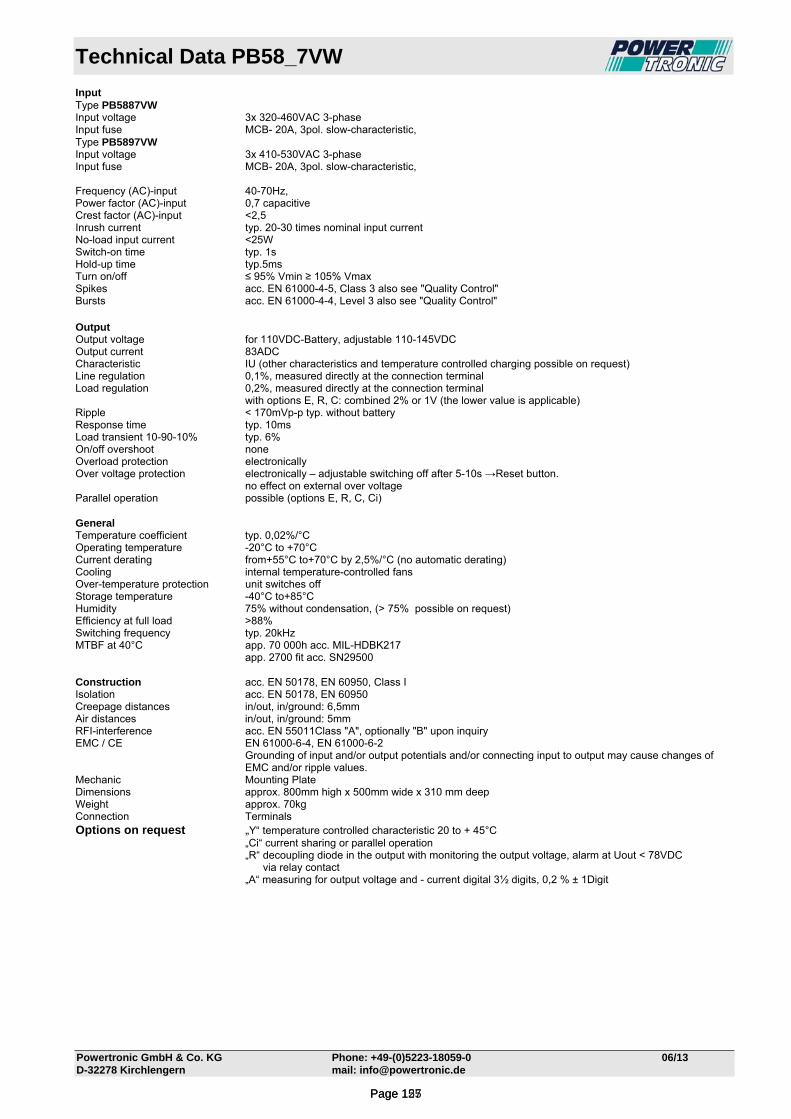
Technical Data PB58_7VW
Powertronic GmbH & Co. KG Phone: +49-(0)5223-18059-0 06/13 D-32278 Kirchlengern mail: [email protected]
Input Type PB5887VW Input voltage 3x 320-460VAC 3-phase Input fuse MCB- 20A, 3pol. slow-characteristic, Type PB5897VW Input voltage 3x 410-530VAC 3-phase Input fuse MCB- 20A, 3pol. slow-characteristic, Frequency (AC)-input 40-70Hz, Power factor (AC)-input 0,7 capacitive Crest factor (AC)-input <2,5 Inrush current typ. 20-30 times nominal input current No-load input current <25W Switch-on time typ. 1s Hold-up time typ.5ms Turn on/off ≤ 95% Vmin ≥ 105% Vmax Spikes acc. EN 61000-4-5, Class 3 also see "Quality Control" Bursts acc. EN 61000-4-4, Level 3 also see "Quality Control" Output Output voltage for 110VDC-Battery, adjustable 110-145VDC Output current 83ADC Characteristic IU (other characteristics and temperature controlled charging possible on request) Line regulation 0,1%, measured directly at the connection terminal Load regulation 0,2%, measured directly at the connection terminal with options E, R, C: combined 2% or 1V (the lower value is applicable) Ripple < 170mVp-p typ. without battery Response time typ. 10ms Load transient 10-90-10% typ. 6% On/off overshoot none Overload protection electronically Over voltage protection electronically – adjustable switching off after 5-10s →Reset button. no effect on external over voltage Parallel operation possible (options E, R, C, Ci) General Temperature coefficient typ. 0,02%/°C Operating temperature -20°C to +70°C Current derating from+55°C to+70°C by 2,5%/°C (no automatic derating) Cooling internal temperature-controlled fans Over-temperature protection unit switches off Storage temperature -40°C to+85°C Humidity 75% without condensation, (> 75% possible on request) Efficiency at full load >88% Switching frequency typ. 20kHz MTBF at 40°C app. 70 000h acc. MIL-HDBK217 app. 2700 fit acc. SN29500 Construction acc. EN 50178, EN 60950, Class I Isolation acc. EN 50178, EN 60950 Creepage distances in/out, in/ground: 6,5mm Air distances in/out, in/ground: 5mm RFI-interference acc. EN 55011Class "A", optionally "B" upon inquiry EMC / CE EN 61000-6-4, EN 61000-6-2
Grounding of input and/or output potentials and/or connecting input to output may cause changes of EMC and/or ripple values.
Mechanic Mounting Plate Dimensions approx. 800mm high x 500mm wide x 310 mm deep Weight approx. 70kg Connection Terminals Options on request „Y“ temperature controlled characteristic 20 to + 45°C „Ci“ current sharing or parallel operation „R“ decoupling diode in the output with monitoring the output voltage, alarm at Uout < 78VDC via relay contact „A“ measuring for output voltage and - current digital 3½ digits, 0,2 % ± 1Digit
Page 127Page 155
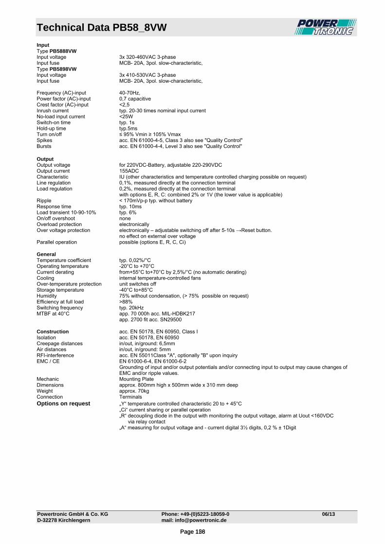
Technical Data PB58_8VW
Powertronic GmbH & Co. KG Phone: +49-(0)5223-18059-0 06/13 D-32278 Kirchlengern mail: [email protected]
Input Type PB5888VW Input voltage 3x 320-460VAC 3-phase Input fuse MCB- 20A, 3pol. slow-characteristic, Type PB5898VW Input voltage 3x 410-530VAC 3-phase Input fuse MCB- 20A, 3pol. slow-characteristic, Frequency (AC)-input 40-70Hz, Power factor (AC)-input 0,7 capacitive Crest factor (AC)-input <2,5 Inrush current typ. 20-30 times nominal input current No-load input current <25W Switch-on time typ. 1s Hold-up time typ.5ms Turn on/off ≤ 95% Vmin ≥ 105% Vmax Spikes acc. EN 61000-4-5, Class 3 also see "Quality Control" Bursts acc. EN 61000-4-4, Level 3 also see "Quality Control" Output Output voltage for 220VDC-Battery, adjustable 220-290VDC Output current 155ADC Characteristic IU (other characteristics and temperature controlled charging possible on request) Line regulation 0,1%, measured directly at the connection terminal Load regulation 0,2%, measured directly at the connection terminal with options E, R, C: combined 2% or 1V (the lower value is applicable) Ripple < 170mVp-p typ. without battery Response time typ. 10ms Load transient 10-90-10% typ. 6% On/off overshoot none Overload protection electronically Over voltage protection electronically – adjustable switching off after 5-10s →Reset button. no effect on external over voltage Parallel operation possible (options E, R, C, Ci) General Temperature coefficient typ. 0,02%/°C Operating temperature -20°C to +70°C Current derating from+55°C to+70°C by 2,5%/°C (no automatic derating) Cooling internal temperature-controlled fans Over-temperature protection unit switches off Storage temperature -40°C to+85°C Humidity 75% without condensation, (> 75% possible on request) Efficiency at full load >88% Switching frequency typ. 20kHz MTBF at 40°C app. 70 000h acc. MIL-HDBK217 app. 2700 fit acc. SN29500 Construction acc. EN 50178, EN 60950, Class I Isolation acc. EN 50178, EN 60950 Creepage distances in/out, in/ground: 6,5mm Air distances in/out, in/ground: 5mm RFI-interference acc. EN 55011Class "A", optionally "B" upon inquiry EMC / CE EN 61000-6-4, EN 61000-6-2
Grounding of input and/or output potentials and/or connecting input to output may cause changes of EMC and/or ripple values.
Mechanic Mounting Plate Dimensions approx. 800mm high x 500mm wide x 310 mm deep Weight approx. 70kg Connection Terminals Options on request „Y“ temperature controlled characteristic 20 to + 45°C „Ci“ current sharing or parallel operation „R“ decoupling diode in the output with monitoring the output voltage, alarm at Uout <160VDC via relay contact „A“ measuring for output voltage and - current digital 3½ digits, 0,2 % ± 1Digit
Page 128Page 156
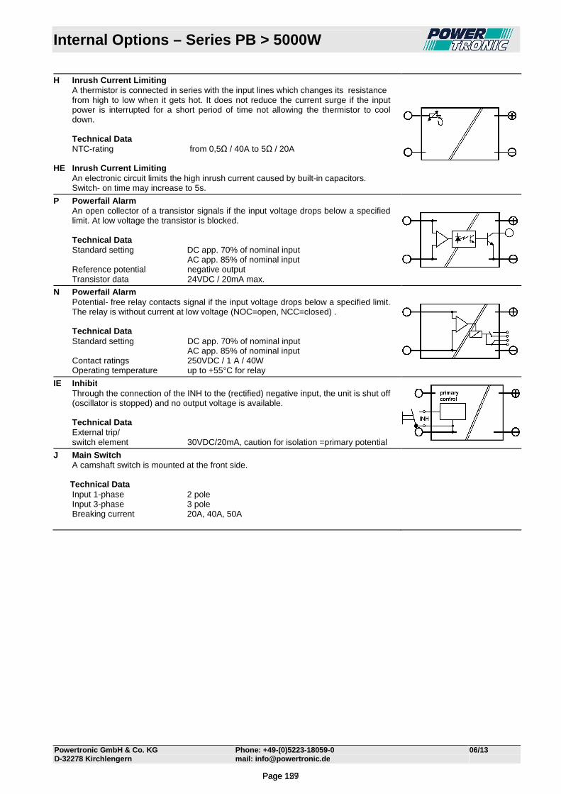
Internal Options – Series PB > 5000W
Powertronic GmbH & Co. KG Phone: +49 -(0)5223-18059-0 06/13 D-32278 Kirchlengern mail: [email protected]
H Inrush Current Limiting A thermistor is connected in series with the input lines which changes its resistance
from high to low when it gets hot. It does not reduce the current surge if the input power is interrupted for a short period of time not allowing the thermistor to cool down.
Technical Data NTC-rating from 0,5Ω / 40A to 5Ω / 20A HE Inrush Current Limiting An electronic circuit limits the high inrush current caused by built-in capacitors. Switch- on time may increase to 5s.
P Powerfail Alarm An open collector of a transistor signals if the input voltage drops below a specified
limit. At low voltage the transistor is blocked. Technical Data Standard setting DC app. 70% of nominal input AC app. 85% of nominal input Reference potential negative output Transistor data 24VDC / 20mA max.
N Powerfail Alarm Potential- free relay contacts signal if the input voltage drops below a specified limit.
The relay is without current at low voltage (NOC=open, NCC=closed) . Technical Data Standard setting DC app. 70% of nominal input AC app. 85% of nominal input Contact ratings 250VDC / 1 A / 40W Operating temperature up to +55°C for relay
IE Inhibit Through the connection of the INH to the (rectified) negative input, the unit is shut off
(oscillator is stopped) and no output voltage is available. Technical Data External trip/ switch element 30VDC/20mA, caution for isolation =primary potential
J Main Switch A camshaft switch is mounted at the front side. Technical Data Input 1-phase 2 pole Input 3-phase 3 pole Breaking current 20A, 40A, 50A
Page 129Page 157
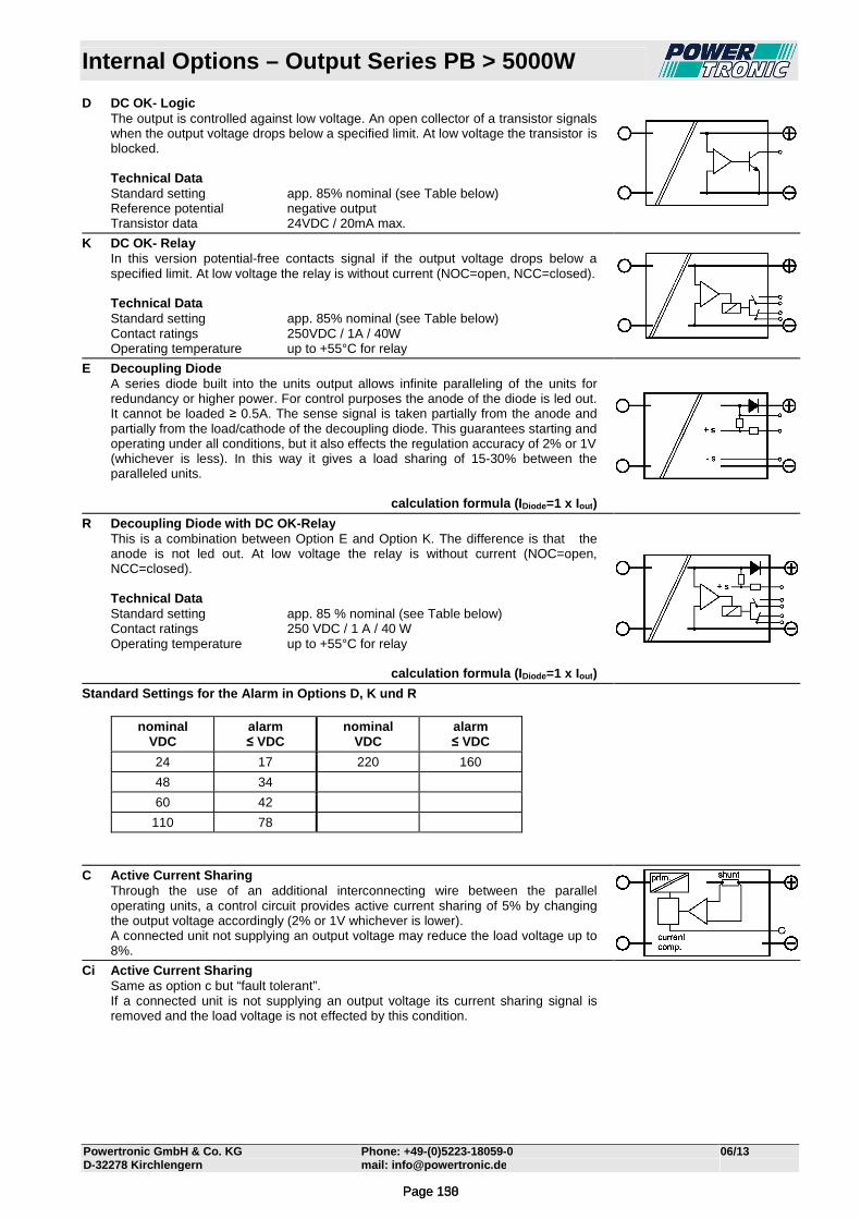
Internal Options – Output Series PB > 5000W
Powertronic GmbH & Co. KG Phone: +49 -(0)5223-18059-0 06/13 D-32278 Kirchlengern mail: [email protected]
D DC OK- Logic The output is controlled against low voltage. An open collector of a transistor signals
when the output voltage drops below a specified limit. At low voltage the transistor is blocked.
Technical Data Standard setting app. 85% nominal (see Table below) Reference potential negative output Transistor data 24VDC / 20mA max.
K DC OK- Relay In this version potential-free contacts signal if the output voltage drops below a
specified limit. At low voltage the relay is without current (NOC=open, NCC=closed). Technical Data Standard setting app. 85% nominal (see Table below) Contact ratings 250VDC / 1A / 40W Operating temperature up to +55°C for relay
E Decoupling Diode A series diode built into the units output allows infinite paralleling of the units for
redundancy or higher power. For control purposes the anode of the diode is led out. It cannot be loaded ≥ 0.5A. The sense signal is taken partially from the anode and partially from the load/cathode of the decoupling diode. This guarantees starting and operating under all conditions, but it also effects the regulation accuracy of 2% or 1V (whichever is less). In this way it gives a load sharing of 15-30% between the paralleled units.
calculation formula (I Diode=1 x Iout )
R Decoupling Diode with DC OK -Relay This is a combination between Option E and Option K. The difference is that the
anode is not led out. At low voltage the relay is without current (NOC=open, NCC=closed).
Technical Data Standard setting app. 85 % nominal (see Table below) Contact ratings 250 VDC / 1 A / 40 W Operating temperature up to +55°C for relay
calculation formula (I Diode=1 x Iout )
Standard Settings for the Alarm in Options D, K und R
nominal VDC
alarm ≤ VDC
nominal VDC
alarm ≤ VDC
24 17 220 160
48 34
60 42
110 78
C Active Current Sharing Through the use of an additional interconnecting wire between the parallel
operating units, a control circuit provides active current sharing of 5% by changing the output voltage accordingly (2% or 1V whichever is lower).
A connected unit not supplying an output voltage may reduce the load voltage up to 8%.
Ci Active Current Sharing Same as option c but “fault tolerant”. If a connected unit is not supplying an output voltage its current sharing signal is
removed and the load voltage is not effected by this condition.
Page 130Page 158
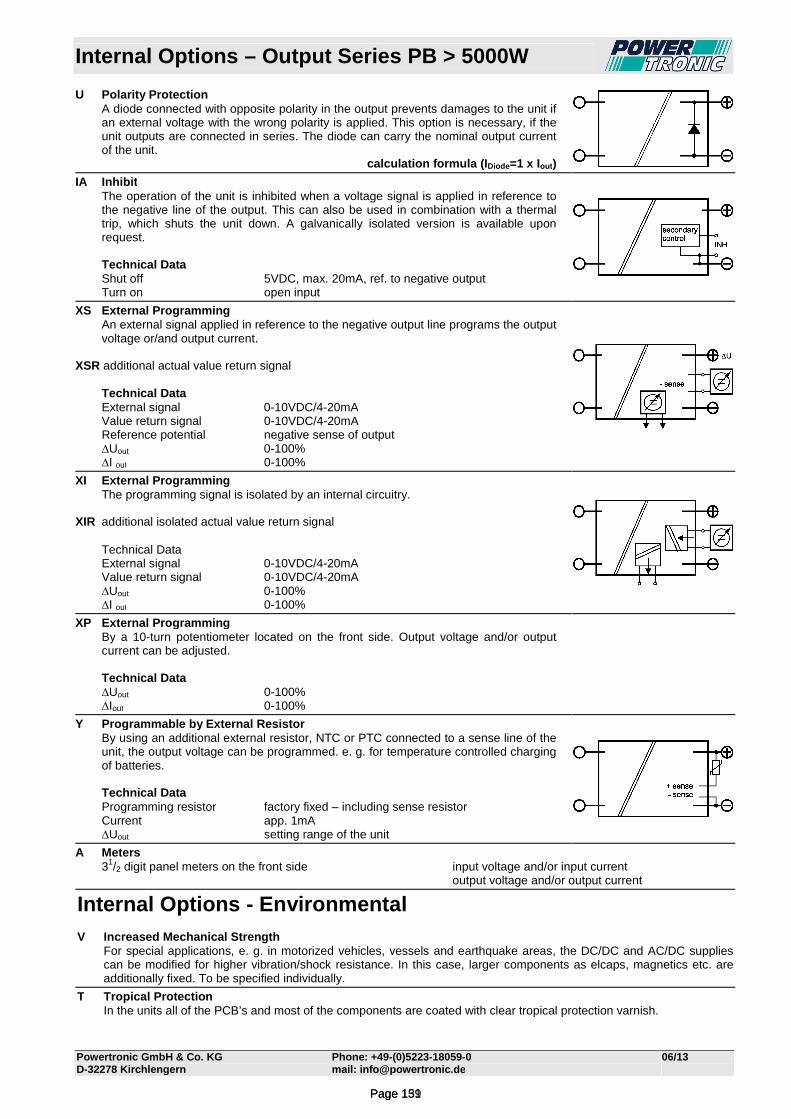
Internal Options – Output Series PB > 5000W
Powertronic GmbH & Co. KG Phone: +49 -(0)5223-18059-0 06/13 D-32278 Kirchlengern mail: [email protected]
U Polarity Protection A diode connected with opposite polarity in the output prevents damages to the unit if
an external voltage with the wrong polarity is applied. This option is necessary, if the unit outputs are connected in series. The diode can carry the nominal output current of the unit.
calculation formula (I Diode=1 x Iout )
IA Inhibit The operation of the unit is inhibited when a voltage signal is applied in reference to
the negative line of the output. This can also be used in combination with a thermal trip, which shuts the unit down. A galvanically isolated version is available upon request.
Technical Data Shut off 5VDC, max. 20mA, ref. to negative output Turn on open input
XS External Programming An external signal applied in reference to the negative output line programs the output
voltage or/and output current. XSR additional actual value return signal Technical Data External signal 0-10VDC/4-20mA Value return signal 0-10VDC/4-20mA Reference potential negative sense of output ∆Uout 0-100% ∆I out 0-100%
XI External Programming The programming signal is isolated by an internal circuitry. XIR additional isolated actual value return signal Technical Data External signal 0-10VDC/4-20mA Value return signal 0-10VDC/4-20mA ∆Uout 0-100% ∆I out 0-100%
XP External Programming By a 10-turn potentiometer located on the front side. Output voltage and/or output
current can be adjusted. Technical Data ∆Uout 0-100% ∆Iout 0-100%
Y Programmable by External Resistor By using an additional external resistor, NTC or PTC connected to a sense line of the
unit, the output voltage can be programmed. e. g. for temperature controlled charging of batteries.
Technical Data Programming resistor factory fixed – including sense resistor Current app. 1mA ∆Uout setting range of the unit
A Meters 31/2 digit panel meters on the front side input voltage and/or input current output voltage and/or output current
Internal Options - Environmental V Increased Mechanical Strength For special applications, e. g. in motorized vehicles, vessels and earthquake areas, the DC/DC and AC/DC supplies
can be modified for higher vibration/shock resistance. In this case, larger components as elcaps, magnetics etc. are additionally fixed. To be specified individually.
T Tropical Protection In the units all of the PCB’s and most of the components are coated with clear tropical protection varnish.
Page 131Page 159
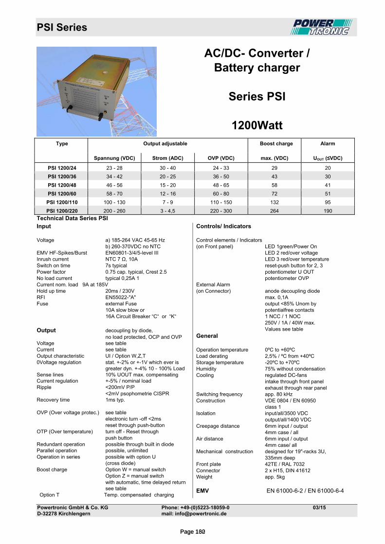
PSI Series
Powertronic GmbH & Co. KG Phone: +49-(0)5223-18059-0 03/15 D-32278 Kirchlengern mail: [email protected]
AC/DC- Converter / Battery charger
Series PSI
1200Watt
Technical Data Series PSI
Type Output adjustable Boost charge Alarm
Spannung (VDC) Strom (ADC) OVP (VDC) max. (VDC) UOUT (≤VDC)
PSI 1200/24 23 - 28 30 - 40 24 - 33 29 20
PSI 1200/36 34 - 42 20 - 25 36 - 50 43 30
PSI 1200/48 46 - 56 15 - 20 48 - 65 58 41
PSI 1200/60 58 - 70 12 - 16 60 - 80 72 51
PSI 1200/110 100 - 130 7 - 9 110 - 150 132 95
PSI 1200/220 200 - 260 3 - 4,5 220 - 300 264 190
Input Voltage a) 185-264 VAC 45-65 Hz b) 260-370VDC no NTC EMV HF-Spikes/Burst EN60801-3/4/5-level III Inrush current NTC 7 Ω, 10A Switch on time 7s typical Power factor 0.75 cap. typical, Crest 2.5 No load current typical 0,25A 1 Current nom. load 9A at 185V Hold up time 20ms / 230V RFI EN55022-"A" Fuse external Fuse 10A slow blow or 16A Circuit Breaker “C“ or “K“ Output decoupling by diode, no load protected, OCP and OVP Voltage see table Current see table Output characteristic UI / Option W,Z,T 0Voltage regulation stat. +-2% or +-1V which ever is greater dyn. +-4% 10 - 100% Load Sense lines 10% UOUT max. compensating Current regulation +-5% / nominal load Ripple <200mV P/P <2mV psophometrie CISPR Recovery time 1ms typ. OVP (Over voltage protec.) see table electronic turn -off <2ms reset through push-button OTP (Over temperature) turn off - Reset through push button Redundant operation possible through built in diode Parallel operation possible, unlimited Operation in series possible with option U (cross diode) Boost charge Option W = manual switch Option Z = manual switch with automatic, time delayed return see table Option T Temp. compensated charging
Controls/ Indicators Control elements / Indicators (on Front panel) LED 1green/Power On LED 2 red/over voltage LED 3 red/over temperature reset-push button for 2, 3 potentiometer U OUT potentiometer OVP External Alarm (on Connector) anode decoupling diode max. 0,1A output <85% Unom by potentialfree contacts 1 NCC / 1 NOC 250V / 1A / 40W max. Values see table General Operation temperature 0ºC to +60ºC Load derating 2,5% / ºC from +40ºC Storage temperature -20ºC to +70ºC Humidity 75% without condensation Cooling regulated DC-fans intake through front panel exhaust through rear panel Switching frequency app. 80 kHz Construction VDE 0804 / EN 60950 class 1 Isolation input/all/3500 VDC output/all/1400 VDC Creepage distance 6mm input / output 4mm case / all Air distance 6mm input / output 4mm case/ all Mechanical construction designed for 19"-racks 3U, 335mm deep Front plate 42TE / RAL 7032 Connector 2 x H15, DIN 41612 Weight app. 5kg EMV EN 61000-6-2 / EN 61000-6-4
Page 132Page 160
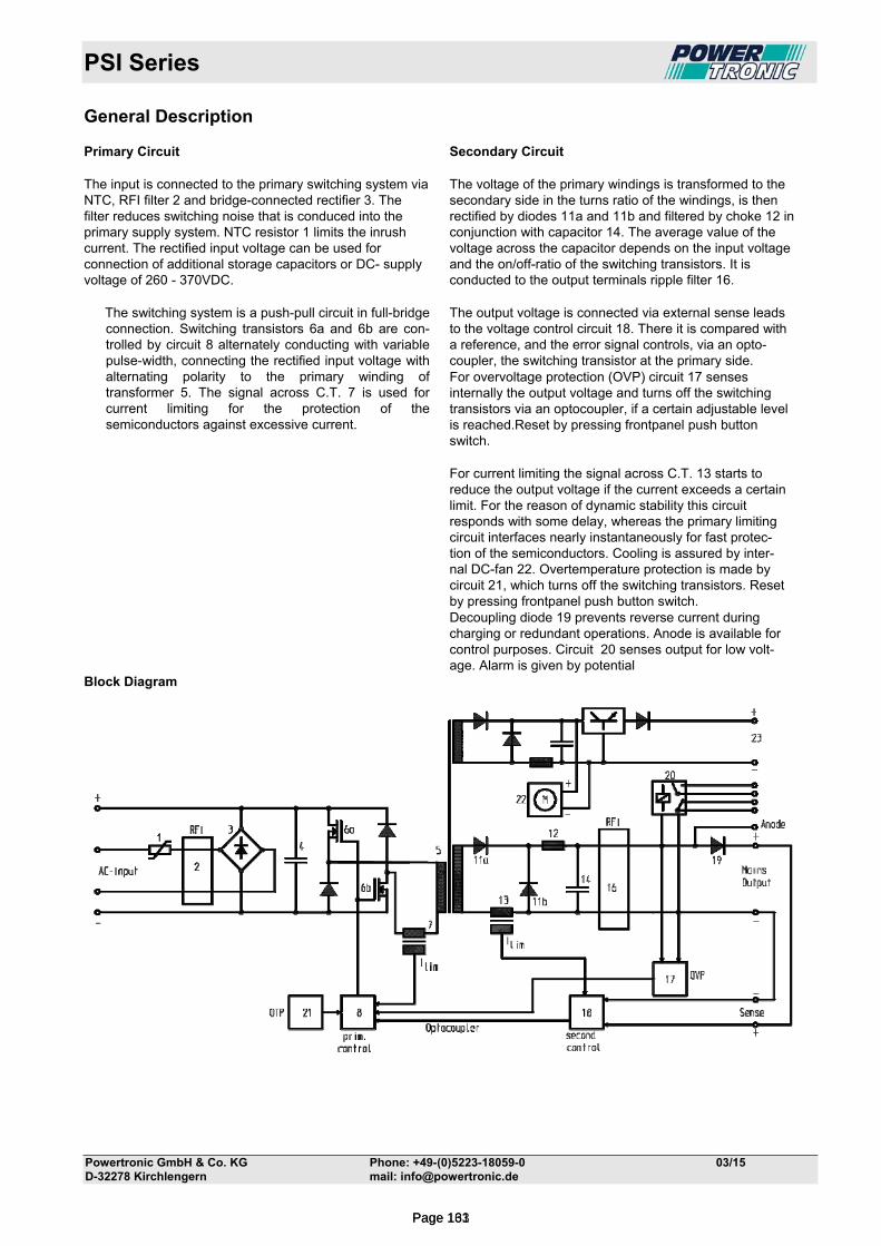
PSI Series
Powertronic GmbH & Co. KG Phone: +49-(0)5223-18059-0 03/15 D-32278 Kirchlengern mail: [email protected]
General Description Primary Circuit The input is connected to the primary switching system via NTC, RFI filter 2 and bridge-connected rectifier 3. The filter reduces switching noise that is conduced into the primary supply system. NTC resistor 1 limits the inrush current. The rectified input voltage can be used for connection of additional storage capacitors or DC- supply voltage of 260 - 370VDC.
The switching system is a push-pull circuit in full-bridge connection. Switching transistors 6a and 6b are con- trolled by circuit 8 alternately conducting with variable pulse-width, connecting the rectified input voltage with alternating polarity to the primary winding of transformer 5. The signal across C.T. 7 is used for current limiting for the protection of the semiconductors against excessive current.
Secondary Circuit The voltage of the primary windings is transformed to the secondary side in the turns ratio of the windings, is then rectified by diodes 11a and 11b and filtered by choke 12 in conjunction with capacitor 14. The average value of the voltage across the capacitor depends on the input voltage and the on/off-ratio of the switching transistors. It is conducted to the output terminals ripple filter 16. The output voltage is connected via external sense leads to the voltage control circuit 18. There it is compared with a reference, and the error signal controls, via an opto-coupler, the switching transistor at the primary side. For overvoltage protection (OVP) circuit 17 senses internally the output voltage and turns off the switching transistors via an optocoupler, if a certain adjustable level is reached.Reset by pressing frontpanel push button switch. For current limiting the signal across C.T. 13 starts to reduce the output voltage if the current exceeds a certain limit. For the reason of dynamic stability this circuit responds with some delay, whereas the primary limiting circuit interfaces nearly instantaneously for fast protec- tion of the semiconductors. Cooling is assured by inter- nal DC-fan 22. Overtemperature protection is made by circuit 21, which turns off the switching transistors. Reset by pressing frontpanel push button switch. Decoupling diode 19 prevents reverse current during charging or redundant operations. Anode is available for control purposes. Circuit 20 senses output for low volt- age. Alarm is given by potential
Block Diagram
Page 133Page 161
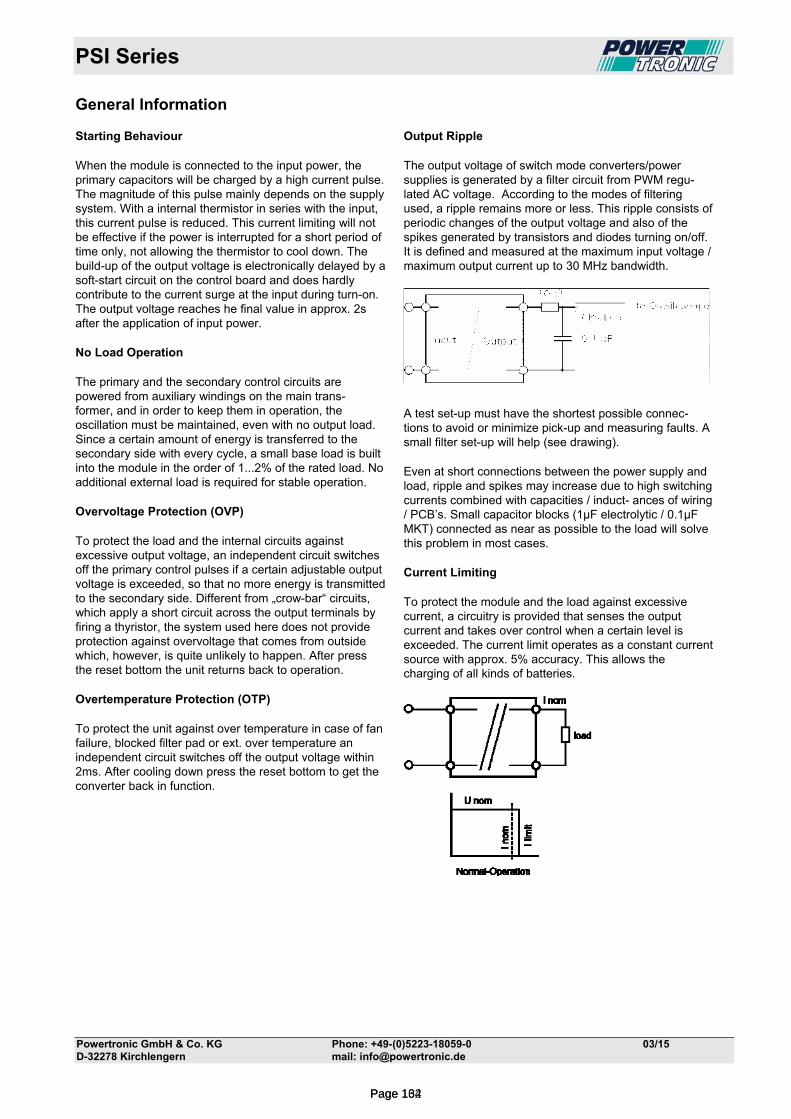
PSI Series
Powertronic GmbH & Co. KG Phone: +49-(0)5223-18059-0 03/15 D-32278 Kirchlengern mail: [email protected]
General Information Starting Behaviour When the module is connected to the input power, the primary capacitors will be charged by a high current pulse. The magnitude of this pulse mainly depends on the supply system. With a internal thermistor in series with the input, this current pulse is reduced. This current limiting will not be effective if the power is interrupted for a short period of time only, not allowing the thermistor to cool down. The build-up of the output voltage is electronically delayed by a soft-start circuit on the control board and does hardly contribute to the current surge at the input during turn-on. The output voltage reaches he final value in approx. 2s after the application of input power. No Load Operation The primary and the secondary control circuits are powered from auxiliary windings on the main trans- former, and in order to keep them in operation, the oscillation must be maintained, even with no output load. Since a certain amount of energy is transferred to the secondary side with every cycle, a small base load is built into the module in the order of 1...2% of the rated load. No additional external load is required for stable operation. Overvoltage Protection (OVP) To protect the load and the internal circuits against excessive output voltage, an independent circuit switches off the primary control pulses if a certain adjustable output voltage is exceeded, so that no more energy is transmitted to the secondary side. Different from „crow-bar“ circuits, which apply a short circuit across the output terminals by firing a thyristor, the system used here does not provide protection against overvoltage that comes from outside which, however, is quite unlikely to happen. After press the reset bottom the unit returns back to operation. Overtemperature Protection (OTP) To protect the unit against over temperature in case of fan failure, blocked filter pad or ext. over temperature an independent circuit switches off the output voltage within 2ms. After cooling down press the reset bottom to get the converter back in function.
Output Ripple The output voltage of switch mode converters/power supplies is generated by a filter circuit from PWM regu- lated AC voltage. According to the modes of filtering used, a ripple remains more or less. This ripple consists of periodic changes of the output voltage and also of the spikes generated by transistors and diodes turning on/off. It is defined and measured at the maximum input voltage / maximum output current up to 30 MHz bandwidth.
A test set-up must have the shortest possible connec- tions to avoid or minimize pick-up and measuring faults. A small filter set-up will help (see drawing). Even at short connections between the power supply and load, ripple and spikes may increase due to high switching currents combined with capacities / induct- ances of wiring / PCB’s. Small capacitor blocks (1µF electrolytic / 0.1µF MKT) connected as near as possible to the load will solve this problem in most cases. Current Limiting To protect the module and the load against excessive current, a circuitry is provided that senses the output current and takes over control when a certain level is exceeded. The current limit operates as a constant current source with approx. 5% accuracy. This allows the charging of all kinds of batteries.
Page 134Page 162
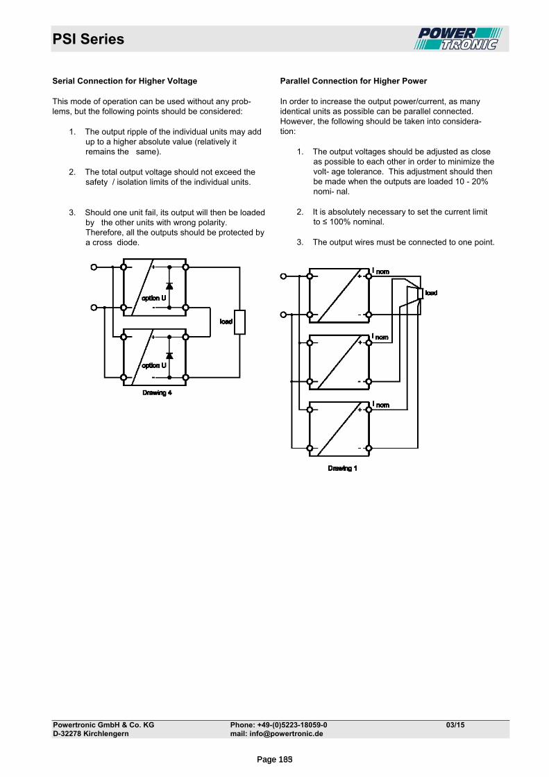
PSI Series
Powertronic GmbH & Co. KG Phone: +49-(0)5223-18059-0 03/15 D-32278 Kirchlengern mail: [email protected]
Serial Connection for Higher Voltage This mode of operation can be used without any prob- lems, but the following points should be considered:
1. The output ripple of the individual units may add up to a higher absolute value (relatively it remains the same).
2. The total output voltage should not exceed the safety / isolation limits of the individual units.
3. Should one unit fail, its output will then be loaded by the other units with wrong polarity. Therefore, all the outputs should be protected by a cross diode.
Parallel Connection for Higher Power In order to increase the output power/current, as many identical units as possible can be parallel connected. However, the following should be taken into considera- tion:
1. The output voltages should be adjusted as close as possible to each other in order to minimize the volt- age tolerance. This adjustment should then be made when the outputs are loaded 10 - 20% nomi- nal.
2. It is absolutely necessary to set the current limit to ≤ 100% nominal.
3. The output wires must be connected to one point.
Page 135Page 163
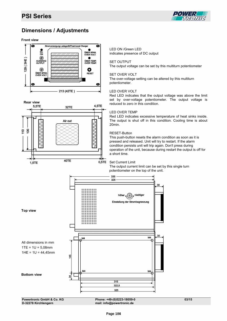
PSI Series
Powertronic GmbH & Co. KG Phone: +49-(0)5223-18059-0 03/15 D-32278 Kirchlengern mail: [email protected]
Dimensions / Adjustments Front view
LED ON /Green LED indicates presence of DC output SET OUTPUT The output voltage can be set by this multiturn potentiometer SET OVER VOLT The over-voltage setting can be altered by this multiturn potentiometer. LED OVER VOLT Red LED indicates that the output voltage was above the limit set by over-voltage potentiometer. The output voltage is reduced to zero in this condition. LED OVER TEMP Red LED indicates excessive temperature of heat sinks inside. The output is shut off in this condition. Cooling time is about 20min. RESET-Button This push-button resets the alarm condition as soon as it is pressed and released. Unit will try to restart. If the alarm condition persists unit will trip again. Don't press during operation of the unit, because during restart the output is off for a short time. Set Current Limit The output current limit can be set by this single turn potentiometer on the top of the unit.
Top view
All dimensions in mm
1TE = 1U = 5,08mm
1HE = 1U = 44,45mm
Bottom view
Rückansicht PSI
Rear view
Page 136Page 164
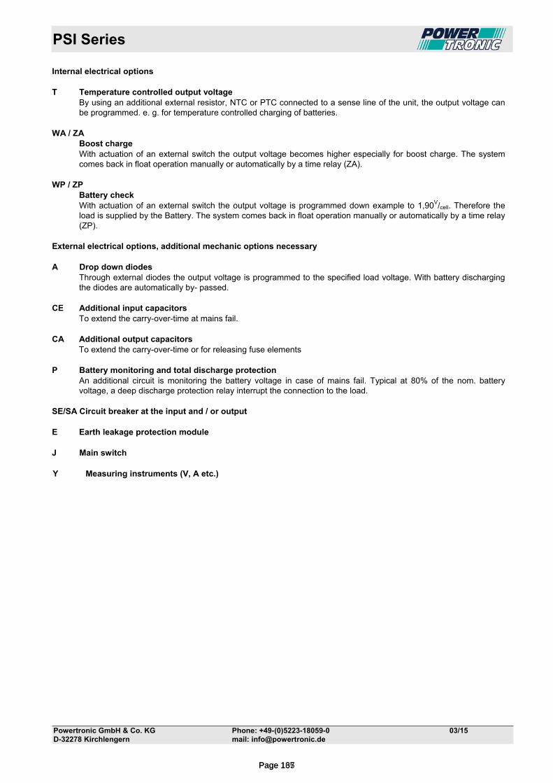
PSI Series
Powertronic GmbH & Co. KG Phone: +49-(0)5223-18059-0 03/15 D-32278 Kirchlengern mail: [email protected]
Internal electrical options T Temperature controlled output voltage By using an additional external resistor, NTC or PTC connected to a sense line of the unit, the output voltage can
be programmed. e. g. for temperature controlled charging of batteries. WA / ZA Boost charge With actuation of an external switch the output voltage becomes higher especially for boost charge. The system
comes back in float operation manually or automatically by a time relay (ZA). WP / ZP Battery check
With actuation of an external switch the output voltage is programmed down example to 1,90V/cell. Therefore the load is supplied by the Battery. The system comes back in float operation manually or automatically by a time relay (ZP).
External electrical options, additional mechanic options necessary A Drop down diodes
Through external diodes the output voltage is programmed to the specified load voltage. With battery discharging the diodes are automatically by- passed.
CE Additional input capacitors To extend the carry-over-time at mains fail. CA Additional output capacitors To extend the carry-over-time or for releasing fuse elements P Battery monitoring and total discharge protection An additional circuit is monitoring the battery voltage in case of mains fail. Typical at 80% of the nom. battery
voltage, a deep discharge protection relay interrupt the connection to the load. SE/SA Circuit breaker at the input and / or output E Earth leakage protection module J Main switch Y Measuring instruments (V, A etc.)
Page 137Page 165
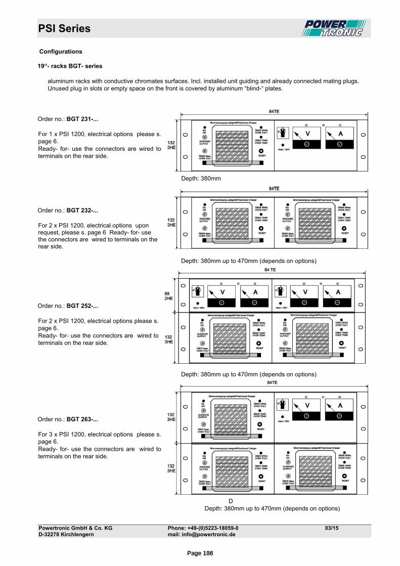
PSI Series
Powertronic GmbH & Co. KG Phone: +49-(0)5223-18059-0 03/15 D-32278 Kirchlengern mail: [email protected]
Configurations 19“- racks BGT- series
aluminum racks with conductive chromates surfaces. Incl. installed unit guiding and already connected mating plugs. Unused plug in slots or empty space on the front is covered by aluminum “blind-“ plates.
Order no.: BGT 231-... For 1 x PSI 1200, electrical options please s. page 6. Ready- for- use the connectors are wired to terminals on the rear side. Depth: 380mm
Order no.: BGT 232-... For 2 x PSI 1200, electrical options upon request, please s. page 6 Ready- for- use the connectors are wired to terminals on the rear side. Depth: 380mm up to 470mm (depends on options) Order no.: BGT 252-... For 2 x PSI 1200, electrical options please s. page 6. Ready- for- use the connectors are wired to terminals on the rear side.
Depth: 380mm up to 470mm (depends on options) Order no.: BGT 263-... For 3 x PSI 1200, electrical options please s. page 6. Ready- for- use the connectors are wired to terminals on the rear side.
DDepth: 380mm up to 470mm (depends on options)
Page 138Page 166
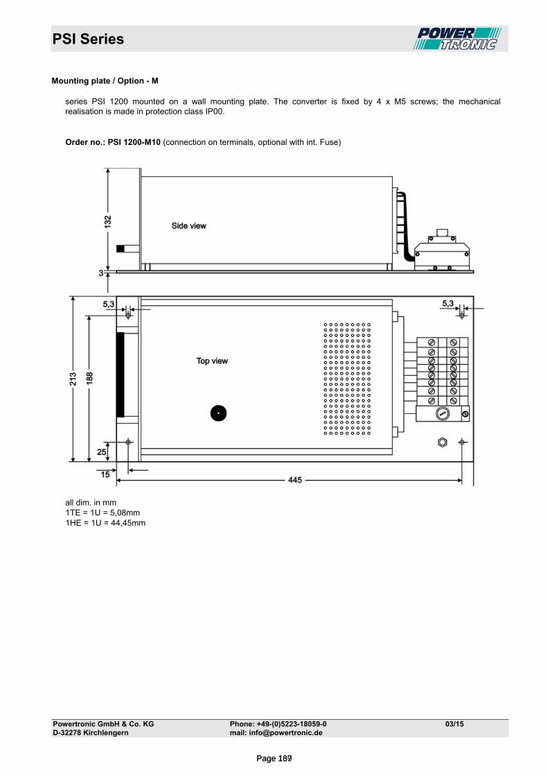
PSI Series
Powertronic GmbH & Co. KG Phone: +49-(0)5223-18059-0 03/15 D-32278 Kirchlengern mail: [email protected]
Mounting plate / Option - M
series PSI 1200 mounted on a wall mounting plate. The converter is fixed by 4 x M5 screws; the mechanical realisation is made in protection class IP00.
Order no.: PSI 1200-M10 (connection on terminals, optional with int. Fuse)
all dim. in mm 1TE = 1U = 5,08mm 1HE = 1U = 44,45mm
Page 139Page 167
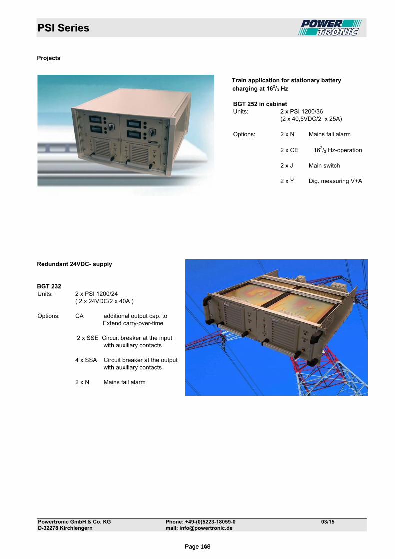
PSI Series
Powertronic GmbH & Co. KG Phone: +49-(0)5223-18059-0 03/15 D-32278 Kirchlengern mail: [email protected]
Projects Train application for stationary battery charging at 162/3 Hz BGT 252 in cabinet Units: 2 x PSI 1200/36 (2 x 40,5VDC/2 x 25A) Options: 2 x N Mains fail alarm
2 x CE 162/3 Hz-operation 2 x J Main switch 2 x Y Dig. measuring V+A Redundant 24VDC- supply BGT 232 Units: 2 x PSI 1200/24 ( 2 x 24VDC/2 x 40A ) Options: CA additional output cap. to
Extend carry-over-time
2 x SSE Circuit breaker at the input with auxiliary contacts 4 x SSA Circuit breaker at the output with auxiliary contacts 2 x N Mains fail alarm
Page 140Page 168
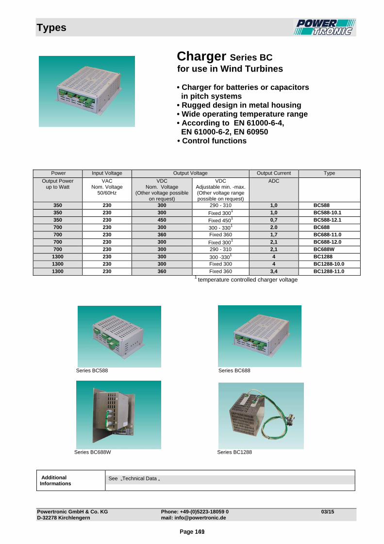
Types
Powertronic GmbH & Co. KG Phone: +49-(0)5223-18059 0 03/15 D-32278 Kirchlengern mail: [email protected]
Charger Series BC for use in Wind Turbines • Charger for batteries or capacitors in pitch systems • Rugged design in metal housing • Wide operating temperature range • According to EN 61000-6-4, EN 61000-6-2, EN 60950 • Control functions
1 temperature controlled charger voltage
Series BC588 Series BC688
Series BC688W Series BC1288
Additional Informations
See „Technical Data „
Power Input Voltage Output Voltage Output Current Type
Output Power up to Watt
VAC Nom. Voltage
50/60Hz
VDC Nom. Voltage
(Other voltage possible on request)
VDC Adjustable min. -max. (Other voltage range possible on request)
ADC
350 230 300 290 - 310 1,0 BC588
350 230 300 Fixed 3001 1,0 BC588-10.1
350 230 450 Fixed 4501 0,7 BC588-12.1
700 230 300 300 - 3301 2.0 BC688
700 230 360 Fixed 360 1,7 BC688-11.0
700 230 300 Fixed 3001 2,1 BC688-12.0
700 230 300 290 - 310 2,1 BC688W
1300 230 300 300 -3301 4 BC1288
1300 230 300 Fixed 300 4 BC1288-10.0
1300 230 360 Fixed 360 3,4 BC1288-11.0
Page 141Page 169
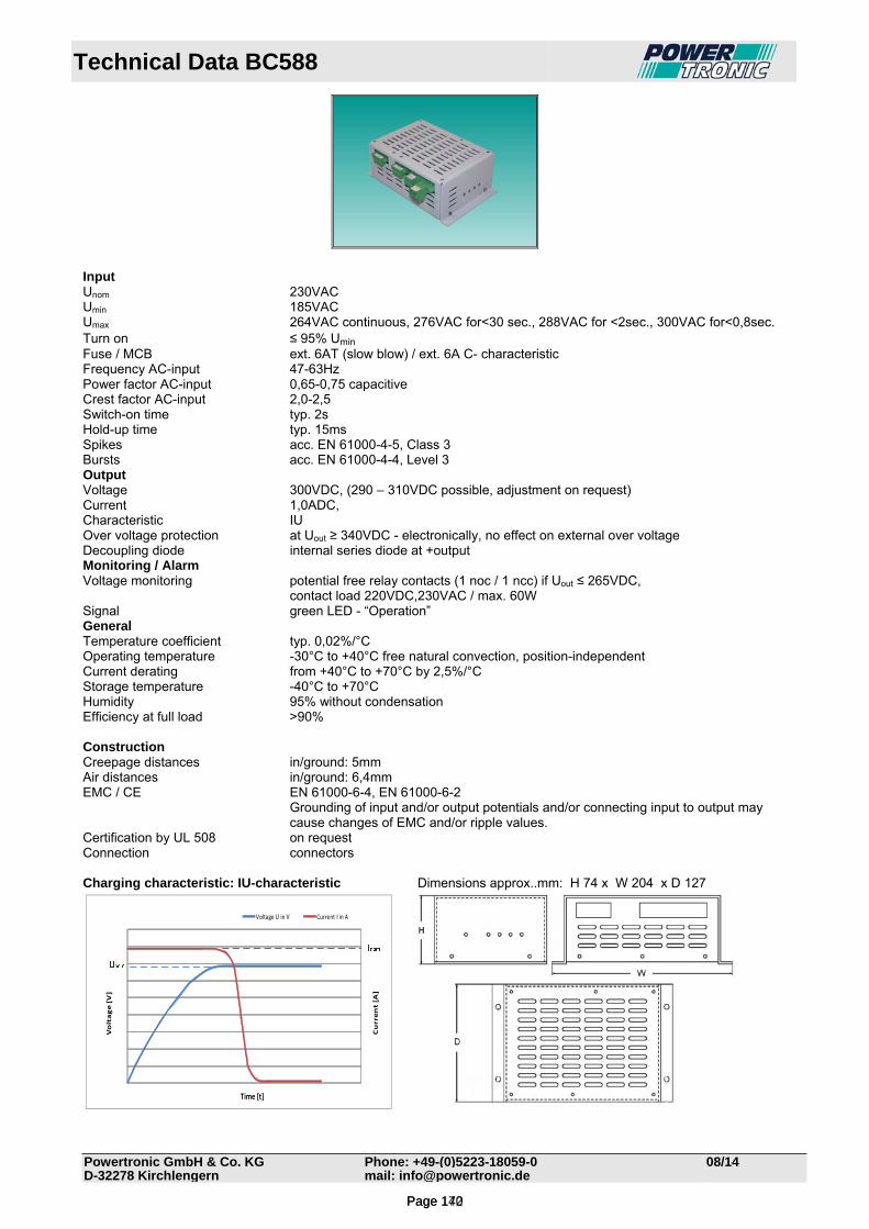
Technical Data BC588
Powertronic GmbH & Co. KG Phone: +49-(0)5223-18059-0 08/14D-32278 Kirchlengern mail: [email protected]
Input Unom 230VAC Umin 185VAC Umax 264VAC continuous, 276VAC for<30 sec., 288VAC for <2sec., 300VAC for<0,8sec. Turn on ≤ 95% Umin Fuse / MCB ext. 6AT (slow blow) / ext. 6A C- characteristic Frequency AC-input 47-63Hz Power factor AC-input 0,65-0,75 capacitive Crest factor AC-input 2,0-2,5 Switch-on time typ. 2s Hold-up time typ. 15ms Spikes acc. EN 61000-4-5, Class 3 Bursts acc. EN 61000-4-4, Level 3 Output Voltage 300VDC, (290 – 310VDC possible, adjustment on request) Current 1,0ADC, Characteristic IU Over voltage protection at Uout ≥ 340VDC - electronically, no effect on external over voltage Decoupling diode internal series diode at +output Monitoring / Alarm Voltage monitoring potential free relay contacts (1 noc / 1 ncc) if Uout ≤ 265VDC, contact load 220VDC,230VAC / max. 60W Signal green LED - “Operation” General Temperature coefficient typ. 0,02%/°C Operating temperature -30°C to +40°C free natural convection, position-independent Current derating from +40°C to +70°C by 2,5%/°C Storage temperature -40°C to +70°C Humidity 95% without condensation Efficiency at full load >90% Construction Creepage distances in/ground: 5mm Air distances in/ground: 6,4mm EMC / CE EN 61000-6-4, EN 61000-6-2
Grounding of input and/or output potentials and/or connecting input to output may cause changes of EMC and/or ripple values.
Certification by UL 508 on request Connection connectors Charging characteristic: IU-characteristic Dimensions approx..mm: H 74 x W 204 x D 127
Current [A]
Voltage [V]
Time [t]
Voltage U in V Current I in A
Page 142Page 170

Technical Data BC588-10.1
Powertronic GmbH & Co. KG Phone: +49-(0)5223-18059-0 08/14 D-32278 Kirchlengern mail: [email protected]
Input Input voltage Unom. 230VAC, voltage range: 185 – 264 VAC
max. permissible stress without destruction or loss of lifetime: 130% (299VAC) for <0,8sec.
125% (288VAC) for 0,8-2sec. 120% (276VAC) for 2- 30sec.
Galvanic isolation primary side to earth 750 VAC and 1000 VDC permanently Fuse / MCB ext. 6AT (slow blow) / ext. 6A K- or D- characteristic Frequency AC-input 47-63Hz Power factor AC-input 0,65-0,75 capacitive Crest factor (AC)-input 2,0-2,5 Turn on voltage down to 90% Umin (167 VAC) Switch-on time typ. 2s Hold-up time Output voltage typical 15ms. Hold up of CPU >2.0s Drop out recovery time Max. 2s Primary Inhibit Inhibit input Digital input, Unom. 230VAC Galvanic isolation Connected with AC - Input Connector 1-wire On / Off levels Signal “0”: pin floating; Signal “1”: shorted with L (phase) Function description Signal “0”: Charging voltage is normal.
Signal “1”: Charging voltage 0VDC Response time Stop: 150ms Start: 150ms Control Input Inhibit input Digital input, Unom. 24VDC Galvanic isolation 750 VAC and 1000 VDC permanently Connector 2-wire On / Off levels Signal “0”: 0-5VDC; Signal “1”: 15-30VDC Input impedance 9100Ω, input current max 25mA Function description Signal “0”: Charging voltage is normal.
Signal “1”: Charging voltage 0VDC Response time Stop: 25ms Start: 25ms PT-100 PT-100 input Range: -40°C to + 80°C. Accuracy: +/- 1°C. Current < 3mA. Galvanic isolation 750 VAC and 1000 VDC permanently Connector 3-wire Temperature error If temperature of battery or capacitors not in the range -20°C to +50°C.
For alarm purposes, the temperature measurement is averaged over 1 sec and with a hysteresis of 5°C.
Temperature sensor error If wire broken or shorted. Output Max charging voltage 330VDC (corresponding to -34°C). Voltage ripple <0.5% (2.25V @ 450V output). Max charging current 1A ± 2%, Voltage / Current Constant current/constant voltage charge system IU- characteristic Galvanic isolation Secondary side to primary side and secondary side to earth: 750 VAC and 1000 VDC
permanently Over voltage protection electronically 340VDC. No effect on external over voltage Feed – back protection internal series diode at +output. Polarity protection in combination with an external main circuit breaker or a fuse, full polarity protection for
the battery connection is possible LED Signal signalizations and indications according to table “alarm output functionality” Alarm output Relay contacts (1noc / 1ncc), contact load 30V / 2A Galvanic isolation 750 VAC and 1000 VDC permanently Alarm hold time min. 1 sec – except after power up.
Page 143Page 171
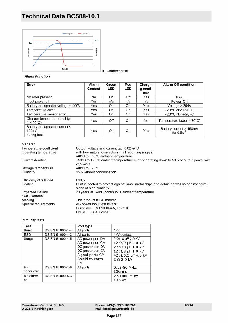
Technical Data BC588-10.1
Powertronic GmbH & Co. KG Phone: +49-(0)5223-18059-0 08/14 D-32278 Kirchlengern mail: [email protected]
Curren
t [A]
Voltage
[V]
Time [t]
Voltage U in V Current I in A
IU Characteristic
General Temperature coefficient Output voltage and current typ. 0,02%/°C Operating temperature with free natural convection in all mounting angles:
-40°C to +50°C ambient temperature Current derating +50°C to +70°C ambient temperature current derating down to 50% of output power with
-2,5%/°C Storage temperature -40°C to +70°C Humidity 95% without condensation Efficiency at full load >90% Coating PCB is coated to protect against small metal chips and debris as well as against corro-
sions at high humidity Expected lifetime 20 years at +40°C continuous ambient temperature EMC General Marking This product is CE marked. Specific requirements AC power input test levels: Surge acc. EN 61000-4-5, Level 3
EN 61000-4-4, Level 3 Immunity tests
Test Port type Burst DS/EN 61000-4-4 All ports 4kV ESD DS/EN 61000-4-2 All ports 4kV contact Surge DS/EN 61000-4-5 AC power port DM
AC power port CM DC power port DM DC power port CM Signal ports CM Shield to earth CM
2 Ω/18 μF 2.0 kV 12 Ω/9 μF 4.0 kV 2 Ω/18 μF 1.0 kV 12 Ω/9 μF 1.0 kV 42 Ω/0.5 μF 4.0 kV 2 Ω 2.0 kV
RF conducted
DS/EN 61000-4-6 All ports 0.15-80 MHz: 10Vrms
RF airbor-ne
DS/EN 61000-4-3 27-1000 MHz: 10 V/m
Alarm Function
Error Alarm Contact
Green LED
Red LED
Charging conti-
nue
Alarm Off condition
No error present No On Off Yes N/A Input power off Yes n/a n/a n/a Power On Battery or capacitor voltage < 400V Yes On On Yes Voltage > 264V Temperature error Yes On On Yes -20°C<t<+50°C Temperature sensor error Yes On On Yes -20°C<t<+50°C Charger temperature too high ( >100°C)
Yes Off On No Temperature lower (<70°C)
Battery or capacitor current < 100mA during test
Yes On On Yes Battery current > 150mA
for 0.5s(5)
Page 144Page 172
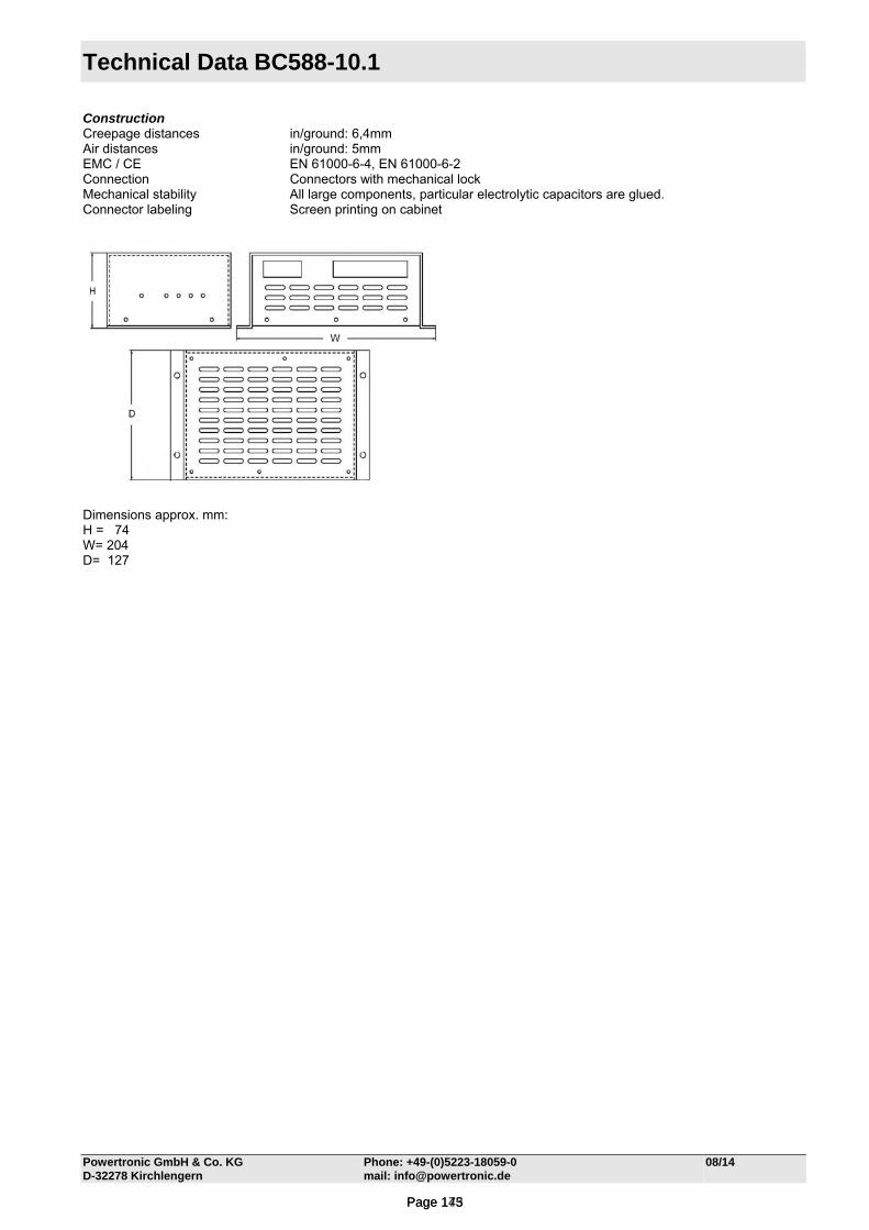
Technical Data BC588-10.1
Powertronic GmbH & Co. KG Phone: +49-(0)5223-18059-0 08/14 D-32278 Kirchlengern mail: [email protected]
Construction Creepage distances in/ground: 6,4mm Air distances in/ground: 5mm EMC / CE EN 61000-6-4, EN 61000-6-2 Connection Connectors with mechanical lock Mechanical stability All large components, particular electrolytic capacitors are glued. Connector labeling Screen printing on cabinet
Dimensions approx. mm: H = 74 W= 204 D= 127
Page 145Page 173
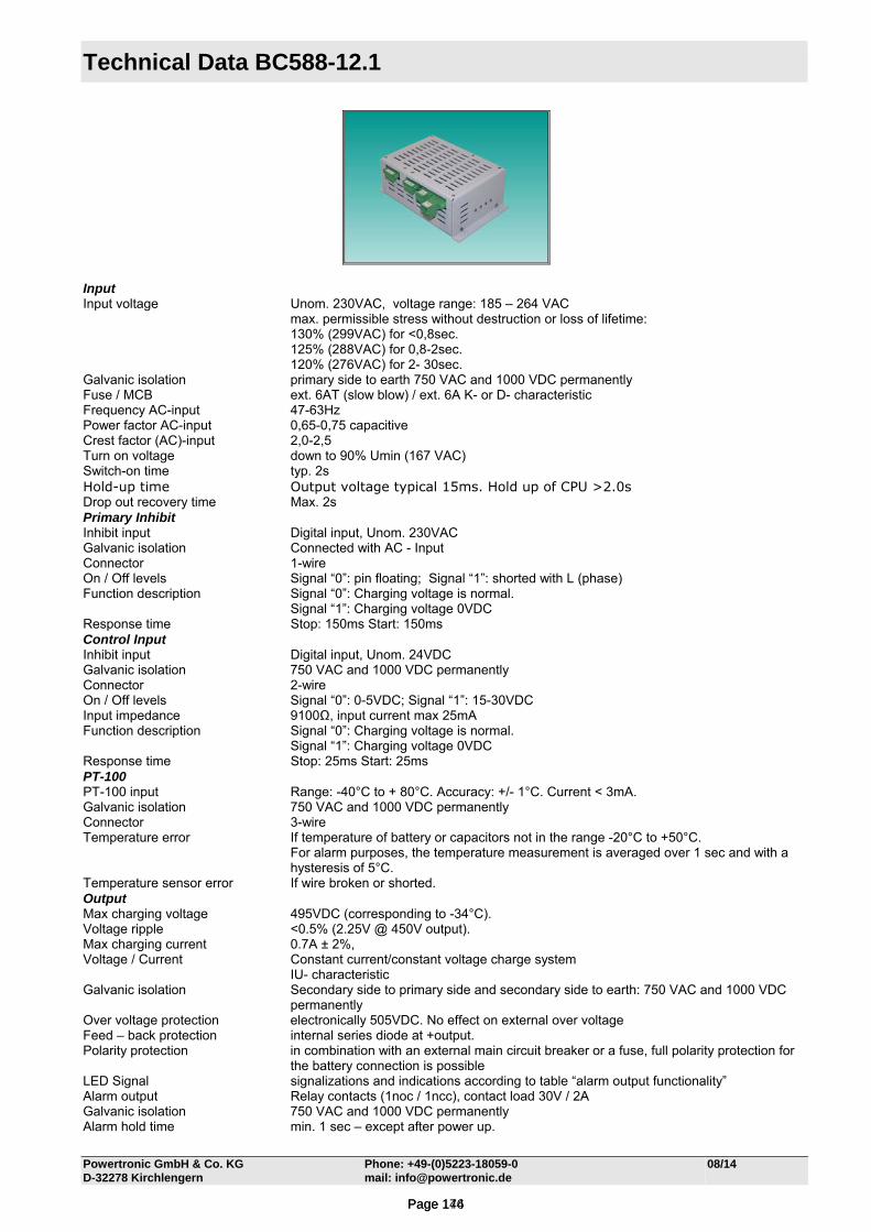
Technical Data BC588-12.1
Powertronic GmbH & Co. KG Phone: +49-(0)5223-18059-0 08/14 D-32278 Kirchlengern mail: [email protected]
Input Input voltage Unom. 230VAC, voltage range: 185 – 264 VAC
max. permissible stress without destruction or loss of lifetime: 130% (299VAC) for <0,8sec.
125% (288VAC) for 0,8-2sec. 120% (276VAC) for 2- 30sec.
Galvanic isolation primary side to earth 750 VAC and 1000 VDC permanently Fuse / MCB ext. 6AT (slow blow) / ext. 6A K- or D- characteristic Frequency AC-input 47-63Hz Power factor AC-input 0,65-0,75 capacitive Crest factor (AC)-input 2,0-2,5 Turn on voltage down to 90% Umin (167 VAC) Switch-on time typ. 2s Hold-up time Output voltage typical 15ms. Hold up of CPU >2.0s Drop out recovery time Max. 2s Primary Inhibit Inhibit input Digital input, Unom. 230VAC Galvanic isolation Connected with AC - Input Connector 1-wire On / Off levels Signal “0”: pin floating; Signal “1”: shorted with L (phase) Function description Signal “0”: Charging voltage is normal.
Signal “1”: Charging voltage 0VDC Response time Stop: 150ms Start: 150ms Control Input Inhibit input Digital input, Unom. 24VDC Galvanic isolation 750 VAC and 1000 VDC permanently Connector 2-wire On / Off levels Signal “0”: 0-5VDC; Signal “1”: 15-30VDC Input impedance 9100Ω, input current max 25mA Function description Signal “0”: Charging voltage is normal.
Signal “1”: Charging voltage 0VDC Response time Stop: 25ms Start: 25ms PT-100 PT-100 input Range: -40°C to + 80°C. Accuracy: +/- 1°C. Current < 3mA. Galvanic isolation 750 VAC and 1000 VDC permanently Connector 3-wire Temperature error If temperature of battery or capacitors not in the range -20°C to +50°C.
For alarm purposes, the temperature measurement is averaged over 1 sec and with a hysteresis of 5°C.
Temperature sensor error If wire broken or shorted. Output Max charging voltage 495VDC (corresponding to -34°C). Voltage ripple <0.5% (2.25V @ 450V output). Max charging current 0.7A ± 2%, Voltage / Current Constant current/constant voltage charge system IU- characteristic Galvanic isolation Secondary side to primary side and secondary side to earth: 750 VAC and 1000 VDC
permanently Over voltage protection electronically 505VDC. No effect on external over voltage Feed – back protection internal series diode at +output. Polarity protection in combination with an external main circuit breaker or a fuse, full polarity protection for
the battery connection is possible LED Signal signalizations and indications according to table “alarm output functionality” Alarm output Relay contacts (1noc / 1ncc), contact load 30V / 2A Galvanic isolation 750 VAC and 1000 VDC permanently Alarm hold time min. 1 sec – except after power up.
Page 146Page 174
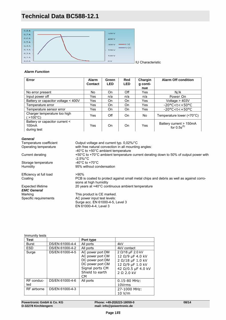
Technical Data BC588-12.1
Powertronic GmbH & Co. KG Phone: +49-(0)5223-18059-0 08/14 D-32278 Kirchlengern mail: [email protected]
IU Characteristic
General Temperature coefficient Output voltage and current typ. 0,02%/°C Operating temperature with free natural convection in all mounting angles:
-40°C to +50°C ambient temperature Current derating +50°C to +70°C ambient temperature current derating down to 50% of output power with
-2,5%/°C Storage temperature -40°C to +70°C Humidity 95% without condensation Efficiency at full load >90% Coating PCB is coated to protect against small metal chips and debris as well as against corro-
sions at high humidity Expected lifetime 20 years at +40°C continuous ambient temperature EMC General Marking This product is CE marked. Specific requirements AC power input test levels: Surge acc. EN 61000-4-5, Level 3
EN 61000-4-4, Level 3
Alarm Function
Error Alarm Contact
Green LED
Red LED
Charging conti-
nue
Alarm Off condition
No error present No On Off Yes N/A Input power off Yes n/a n/a n/a Power On Battery or capacitor voltage < 400V Yes On On Yes Voltage > 403V Temperature error Yes On On Yes -20°C<t<+50°C Temperature sensor error Yes On On Yes -20°C<t<+50°C Charger temperature too high ( >100°C)
Yes Off On No Temperature lower (<70°C)
Battery or capacitor current < 100mA during test
Yes On On Yes Battery current > 150mA
for 0.5s(5)
Immunity tests Test Port type Burst DS/EN 61000-4-4 All ports 4kV ESD DS/EN 61000-4-2 All ports 4kV contact Surge DS/EN 61000-4-5 AC power port DM
AC power port CM DC power port DM DC power port CM Signal ports CM Shield to earth CM
2 Ω/18 μF 2.0 kV 12 Ω/9 μF 4.0 kV 2 Ω/18 μF 1.0 kV 12 Ω/9 μF 1.0 kV 42 Ω/0.5 μF 4.0 kV 2 Ω 2.0 kV
RF conduc-ted
DS/EN 61000-4-6 All ports 0.15-80 MHz: 10Vrms
RF airborne DS/EN 61000-4-3 27-1000 MHz: 10 V/m
Page 147Page 175
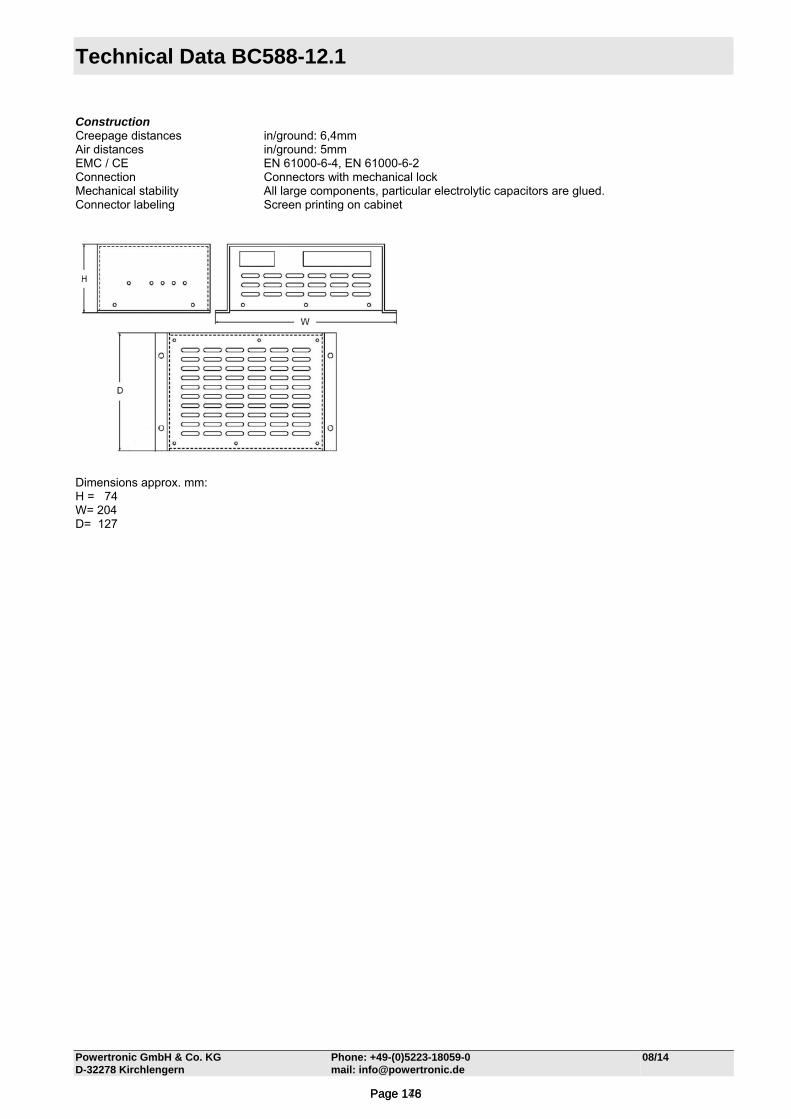
Technical Data BC588-12.1
Powertronic GmbH & Co. KG Phone: +49-(0)5223-18059-0 08/14 D-32278 Kirchlengern mail: [email protected]
Construction Creepage distances in/ground: 6,4mm Air distances in/ground: 5mm EMC / CE EN 61000-6-4, EN 61000-6-2 Connection Connectors with mechanical lock Mechanical stability All large components, particular electrolytic capacitors are glued. Connector labeling Screen printing on cabinet
Dimensions approx. mm: H = 74 W= 204 D= 127
Page 148Page 176
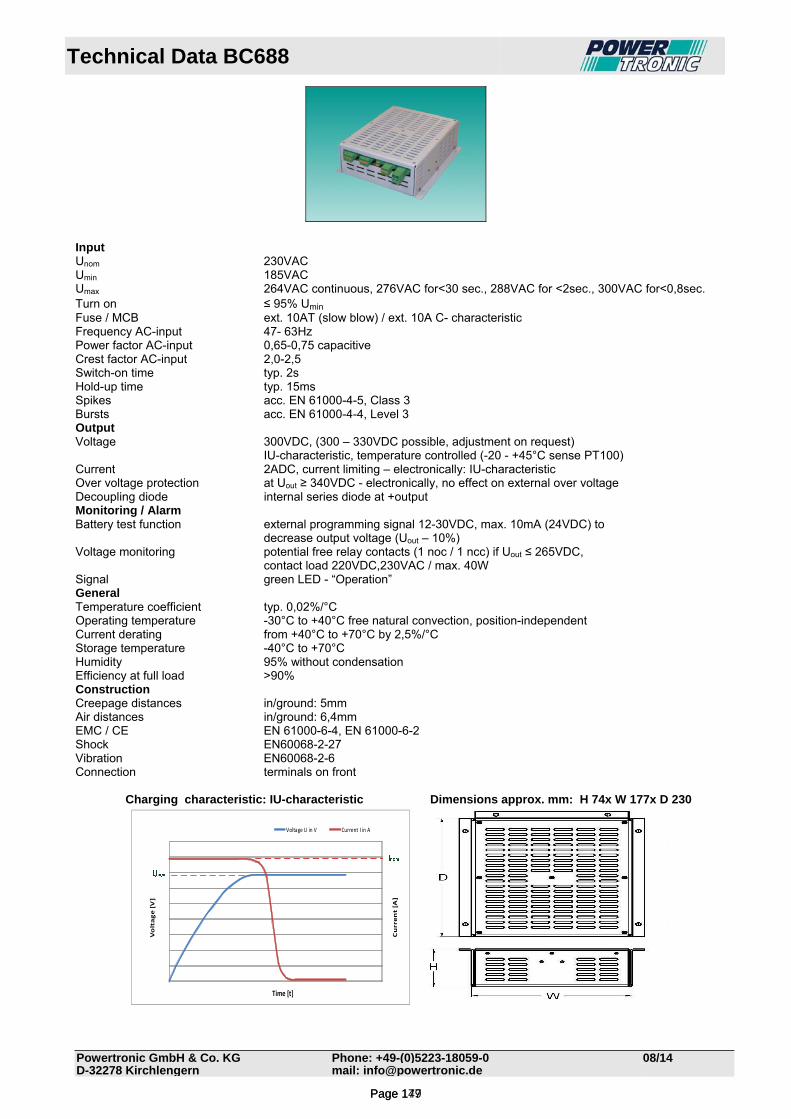
Technical Data BC688
Powertronic GmbH & Co. KG Phone: +49-(0)5223-18059-0 08/14D-32278 Kirchlengern mail: [email protected]
Input Unom 230VAC Umin 185VAC Umax 264VAC continuous, 276VAC for<30 sec., 288VAC for <2sec., 300VAC for<0,8sec. Turn on ≤ 95% Umin Fuse / MCB ext. 10AT (slow blow) / ext. 10A C- characteristic Frequency AC-input 47- 63Hz Power factor AC-input 0,65-0,75 capacitive Crest factor AC-input 2,0-2,5 Switch-on time typ. 2s Hold-up time typ. 15ms Spikes acc. EN 61000-4-5, Class 3 Bursts acc. EN 61000-4-4, Level 3 Output Voltage 300VDC, (300 – 330VDC possible, adjustment on request) IU-characteristic, temperature controlled (-20 - +45°C sense PT100) Current 2ADC, current limiting – electronically: IU-characteristic Over voltage protection at Uout ≥ 340VDC - electronically, no effect on external over voltage Decoupling diode internal series diode at +output Monitoring / Alarm Battery test function external programming signal 12-30VDC, max. 10mA (24VDC) to decrease output voltage (Uout – 10%) Voltage monitoring potential free relay contacts (1 noc / 1 ncc) if Uout ≤ 265VDC, contact load 220VDC,230VAC / max. 40W Signal green LED - “Operation” General Temperature coefficient typ. 0,02%/°C Operating temperature -30°C to +40°C free natural convection, position-independent Current derating from +40°C to +70°C by 2,5%/°C Storage temperature -40°C to +70°C Humidity 95% without condensation Efficiency at full load >90% Construction Creepage distances in/ground: 5mm Air distances in/ground: 6,4mm EMC / CE EN 61000-6-4, EN 61000-6-2 Shock EN60068-2-27 Vibration EN60068-2-6 Connection terminals on front Charging characteristic: IU-characteristic Dimensions approx. mm: H 74x W 177x D 230
Current [A]
Voltage [V]
Time [t]
Voltage U in V Current I in A
Page 149Page 177
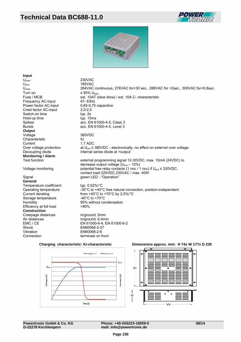
Technical Data BC688-11.0
Powertronic GmbH & Co. KG Phone: +49-(0)5223-18059-0 08/14D-32278 Kirchlengern mail: [email protected]
Input Unom 230VAC Umin 185VAC Umax 264VAC continuous, 276VAC for<30 sec., 288VAC for <2sec., 300VAC for<0,8sec. Turn on ≤ 95% Umin Fuse / MCB ext. 10AT (slow blow) / ext. 10A C- characteristic Frequency AC-input 47- 63Hz Power factor AC-input 0,65-0,75 capacitive Crest factor AC-input 2,0-2,5 Switch-on time typ. 2s Hold-up time typ. 15ms Spikes acc. EN 61000-4-5, Class 3 Bursts acc. EN 61000-4-4, Level 3 Output Voltage 360VDC Characteristic IU Current 1,7 ADC Over voltage protection at Uout ≥ 380VDC - electronically, no effect on external over voltage Decoupling diode internal series diode at +output Monitoring / Alarm Test function external programming signal 12-30VDC, max. 10mA (24VDC) to decrease output voltage (Uout – 10%) Voltage monitoring potential free relay contacts (1 noc / 1 ncc) if Uout ≤ 320VDC, contact load 220VDC,230VAC / max. 40W Signal green LED - “Operation” General Temperature coefficient typ. 0,02%/°C Operating temperature -30°C to +40°C free natural convection, position-independent Current derating from +40°C to +70°C by 2,5%/°C Storage temperature -40°C to +70°C Humidity 95% without condensation Efficiency at full load >90% Construction Creepage distances in/ground: 5mm Air distances in/ground: 6,4mm EMC / CE EN 61000-6-4, EN 61000-6-2 Shock EN60068-2-27 Vibration EN60068-2-6 Connection terminals on front Charging characteristic: IU-characteristic Dimensions approx. mm: H 74x W 177x D 230
Current [A]
Voltage [V]
Time [t]
Voltage U in V Current I in A
Page 150Page 178

Technical Data BC688-11.0
Powertronic GmbH & Co. KG Phone: +49-(0)5223-18059-0 08/14D-32278 Kirchlengern mail: [email protected]
Input Unom 230VAC Umin 185VAC Umax 264VAC continuous, 276VAC for<30 sec., 288VAC for <2sec., 300VAC for<0,8sec. Turn on ≤ 95% Umin Fuse / MCB ext. 10AT (slow blow) / ext. 10A C- characteristic Frequency AC-input 47- 63Hz Power factor AC-input 0,65-0,75 capacitive Crest factor AC-input 2,0-2,5 Switch-on time typ. 2s Hold-up time typ. 15ms Spikes acc. EN 61000-4-5, Class 3 Bursts acc. EN 61000-4-4, Level 3 Output Voltage 360VDC Characteristic IU Current 1,7 ADC Over voltage protection at Uout ≥ 380VDC - electronically, no effect on external over voltage Decoupling diode internal series diode at +output Monitoring / Alarm Test function external programming signal 12-30VDC, max. 10mA (24VDC) to decrease output voltage (Uout – 10%) Voltage monitoring potential free relay contacts (1 noc / 1 ncc) if Uout ≤ 320VDC, contact load 220VDC,230VAC / max. 40W Signal green LED - “Operation” General Temperature coefficient typ. 0,02%/°C Operating temperature -30°C to +40°C free natural convection, position-independent Current derating from +40°C to +70°C by 2,5%/°C Storage temperature -40°C to +70°C Humidity 95% without condensation Efficiency at full load >90% Construction Creepage distances in/ground: 5mm Air distances in/ground: 6,4mm EMC / CE EN 61000-6-4, EN 61000-6-2 Shock EN60068-2-27 Vibration EN60068-2-6 Connection terminals on front Charging characteristic: IU-characteristic Dimensions approx. mm: H 74x W 177x D 230
Current [A]
Voltage [V]
Time [t]
Voltage U in V Current I in A
Page 151Page 179
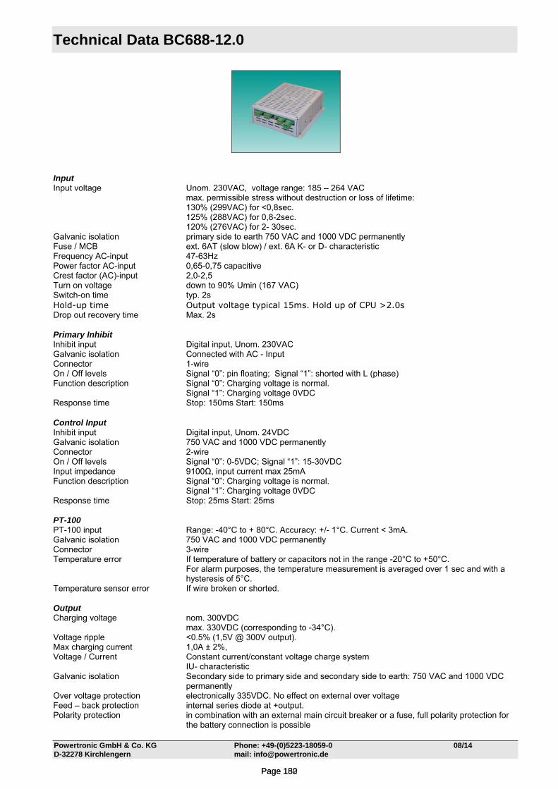
Technical Data BC688-12.0
Powertronic GmbH & Co. KG Phone: +49-(0)5223-18059-0 08/14 D-32278 Kirchlengern mail: [email protected]
Input Input voltage Unom. 230VAC, voltage range: 185 – 264 VAC
max. permissible stress without destruction or loss of lifetime: 130% (299VAC) for <0,8sec.
125% (288VAC) for 0,8-2sec. 120% (276VAC) for 2- 30sec.
Galvanic isolation primary side to earth 750 VAC and 1000 VDC permanently Fuse / MCB ext. 6AT (slow blow) / ext. 6A K- or D- characteristic Frequency AC-input 47-63Hz Power factor AC-input 0,65-0,75 capacitive Crest factor (AC)-input 2,0-2,5 Turn on voltage down to 90% Umin (167 VAC) Switch-on time typ. 2s Hold-up time Output voltage typical 15ms. Hold up of CPU >2.0s Drop out recovery time Max. 2s Primary Inhibit Inhibit input Digital input, Unom. 230VAC Galvanic isolation Connected with AC - Input Connector 1-wire On / Off levels Signal “0”: pin floating; Signal “1”: shorted with L (phase) Function description Signal “0”: Charging voltage is normal.
Signal “1”: Charging voltage 0VDC Response time Stop: 150ms Start: 150ms Control Input Inhibit input Digital input, Unom. 24VDC Galvanic isolation 750 VAC and 1000 VDC permanently Connector 2-wire On / Off levels Signal “0”: 0-5VDC; Signal “1”: 15-30VDC Input impedance 9100Ω, input current max 25mA Function description Signal “0”: Charging voltage is normal.
Signal “1”: Charging voltage 0VDC Response time Stop: 25ms Start: 25ms PT-100 PT-100 input Range: -40°C to + 80°C. Accuracy: +/- 1°C. Current < 3mA. Galvanic isolation 750 VAC and 1000 VDC permanently Connector 3-wire Temperature error If temperature of battery or capacitors not in the range -20°C to +50°C.
For alarm purposes, the temperature measurement is averaged over 1 sec and with a hysteresis of 5°C.
Temperature sensor error If wire broken or shorted. Output Charging voltage nom. 300VDC
max. 330VDC (corresponding to -34°C). Voltage ripple <0.5% (1,5V @ 300V output). Max charging current 1,0A ± 2%, Voltage / Current Constant current/constant voltage charge system IU- characteristic Galvanic isolation Secondary side to primary side and secondary side to earth: 750 VAC and 1000 VDC
permanently Over voltage protection electronically 335VDC. No effect on external over voltage Feed – back protection internal series diode at +output. Polarity protection in combination with an external main circuit breaker or a fuse, full polarity protection for
the battery connection is possible
Page 152Page 180
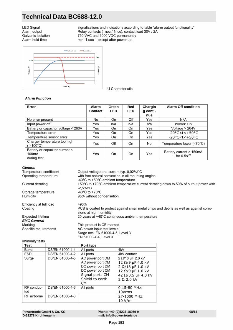
Technical Data BC688-12.0
Powertronic GmbH & Co. KG Phone: +49-(0)5223-18059-0 08/14 D-32278 Kirchlengern mail: [email protected]
LED Signal signalizations and indications according to table “alarm output functionality” Alarm output Relay contacts (1noc / 1ncc), contact load 30V / 2A Galvanic isolation 750 VAC and 1000 VDC permanently Alarm hold time min. 1 sec – except after power up.
Curren
t [A]
Voltage
[V]
Time [t]
Voltage U in V Current I in A
IU Characteristic
General Temperature coefficient Output voltage and current typ. 0,02%/°C Operating temperature with free natural convection in all mounting angles:
-40°C to +50°C ambient temperature Current derating +50°C to +70°C ambient temperature current derating down to 50% of output power with
-2,5%/°C Storage temperature -40°C to +70°C Humidity 95% without condensation Efficiency at full load >90% Coating PCB is coated to protect against small metal chips and debris as well as against corro-
sions at high humidity Expected lifetime 20 years at +40°C continuous ambient temperature EMC General Marking This product is CE marked. Specific requirements AC power input test levels:
Surge acc. EN 61000-4-5, Level 3 EN 61000-4-4, Level 3
Immunity tests Test Port type Burst DS/EN 61000-4-4 All ports 4kV ESD DS/EN 61000-4-2 All ports 4kV contact Surge DS/EN 61000-4-5 AC power port DM
AC power port CM DC power port DM DC power port CM Signal ports CM Shield to earth CM
2 Ω/18 μF 2.0 kV 12 Ω/9 μF 4.0 kV 2 Ω/18 μF 1.0 kV 12 Ω/9 μF 1.0 kV 42 Ω/0.5 μF 4.0 kV 2 Ω 2.0 kV
RF conduc-ted
DS/EN 61000-4-6 All ports 0.15-80 MHz: 10Vrms
RF airborne DS/EN 61000-4-3 27-1000 MHz: 10 V/m
Alarm Function
Error Alarm Contact
Green LED
Red LED
Charging conti-
nue
Alarm Off condition
No error present No On Off Yes N/A Input power off Yes n/a n/a n/a Power On Battery or capacitor voltage < 260V Yes On On Yes Voltage > 264V Temperature error Yes On On Yes -20°C<t<+50°C Temperature sensor error Yes On On Yes -20°C<t<+50°C Charger temperature too high ( >100°C)
Yes Off On No Temperature lower (<70°C)
Battery or capacitor current < 100mA during test
Yes On On Yes Battery current > 150mA
for 0.5s(5)
Page 153Page 181
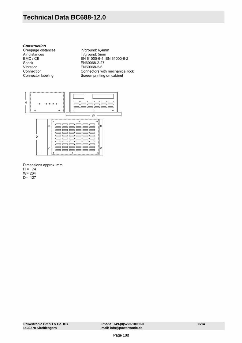
Technical Data BC688-12.0
Powertronic GmbH & Co. KG Phone: +49-(0)5223-18059-0 08/14 D-32278 Kirchlengern mail: [email protected]
Construction Creepage distances in/ground: 6,4mm Air distances in/ground: 5mm EMC / CE EN 61000-6-4, EN 61000-6-2 Shock EN60068-2-27 Vibration EN60068-2-6 Connection Connectors with mechanical lock Connector labeling Screen printing on cabinet
Dimensions approx. mm: H = 74 W= 204 D= 127
Page 154Page 182
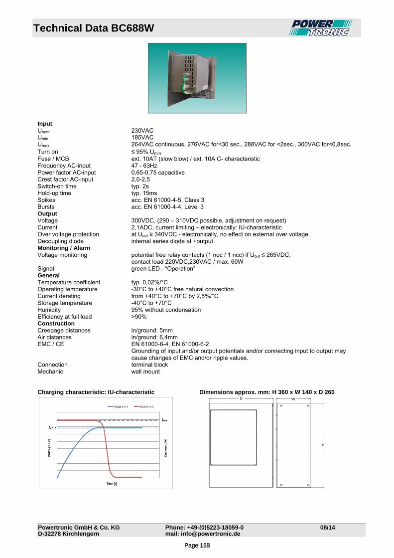
Technical Data BC688W
Powertronic GmbH & Co. KG Phone: +49-(0)5223-18059-0 08/14D-32278 Kirchlengern mail: [email protected]
Input Unom 230VAC Umin 185VAC Umax 264VAC continuous, 276VAC for<30 sec., 288VAC for <2sec., 300VAC for<0,8sec. Turn on ≤ 95% Umin Fuse / MCB ext. 10AT (slow blow) / ext. 10A C- characteristic Frequency AC-input 47 - 63Hz Power factor AC-input 0,65-0,75 capacitive Crest factor AC-input 2,0-2,5 Switch-on time typ. 2s Hold-up time typ. 15ms Spikes acc. EN 61000-4-5, Class 3 Bursts acc. EN 61000-4-4, Level 3 Output Voltage 300VDC, (290 – 310VDC possible, adjustment on request) Current 2,1ADC, current limiting – electronically: IU-characteristic Over voltage protection at Uout ≥ 340VDC - electronically, no effect on external over voltage Decoupling diode internal series diode at +output Monitoring / Alarm Voltage monitoring potential free relay contacts (1 noc / 1 ncc) if Uout ≤ 265VDC, contact load 220VDC,230VAC / max. 60W Signal green LED - “Operation” General Temperature coefficient typ. 0,02%/°C Operating temperature -30°C to +40°C free natural convection Current derating from +40°C to +70°C by 2,5%/°C Storage temperature -40°C to +70°C Humidity 95% without condensation Efficiency at full load >90% Construction Creepage distances in/ground: 5mm Air distances in/ground: 6,4mm EMC / CE EN 61000-6-4, EN 61000-6-2
Grounding of input and/or output potentials and/or connecting input to output may cause changes of EMC and/or ripple values.
Connection terminal block Mechanic wall mount Charging characteristic: IU-characteristic Dimensions approx. mm: H 360 x W 140 x D 260
Current [A]
Voltage [V]
Time [t]
Voltage U in V Current I in A
Page 155Page 183
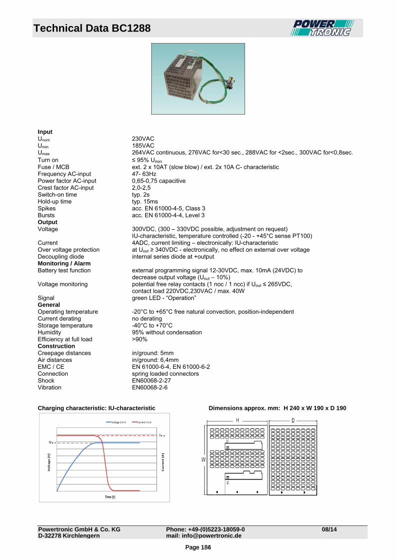
Technical Data BC1288
Powertronic GmbH & Co. KG Phone: +49-(0)5223-18059-0 08/14D-32278 Kirchlengern mail: [email protected]
Input Unom 230VAC Umin 185VAC Umax 264VAC continuous, 276VAC for<30 sec., 288VAC for <2sec., 300VAC for<0,8sec. Turn on ≤ 95% Umin Fuse / MCB ext. 2 x 10AT (slow blow) / ext. 2x 10A C- characteristic Frequency AC-input 47- 63Hz Power factor AC-input 0,65-0,75 capacitive Crest factor AC-input 2,0-2,5 Switch-on time typ. 2s Hold-up time typ. 15ms Spikes acc. EN 61000-4-5, Class 3 Bursts acc. EN 61000-4-4, Level 3 Output Voltage 300VDC, (300 – 330VDC possible, adjustment on request) IU-characteristic, temperature controlled (-20 - +45°C sense PT100) Current 4ADC, current limiting – electronically: IU-characteristic Over voltage protection at Uout ≥ 340VDC - electronically, no effect on external over voltage Decoupling diode internal series diode at +output Monitoring / Alarm Battery test function external programming signal 12-30VDC, max. 10mA (24VDC) to decrease output voltage (Uout – 10%) Voltage monitoring potential free relay contacts (1 noc / 1 ncc) if Uout ≤ 265VDC, contact load 220VDC,230VAC / max. 40W Signal green LED - “Operation” General Operating temperature -20°C to +65°C free natural convection, position-independent Current derating no derating Storage temperature -40°C to +70°C Humidity 95% without condensation Efficiency at full load >90% Construction Creepage distances in/ground: 5mm Air distances in/ground: 6,4mm EMC / CE EN 61000-6-4, EN 61000-6-2 Connection spring loaded connectors Shock EN60068-2-27 Vibration EN60068-2-6 Charging characteristic: IU-characteristic Dimensions approx. mm: H 240 x W 190 x D 190
Current [A]
Voltage [V]
Time [t]
Voltage U in V Current I in A
Page 156Page 184
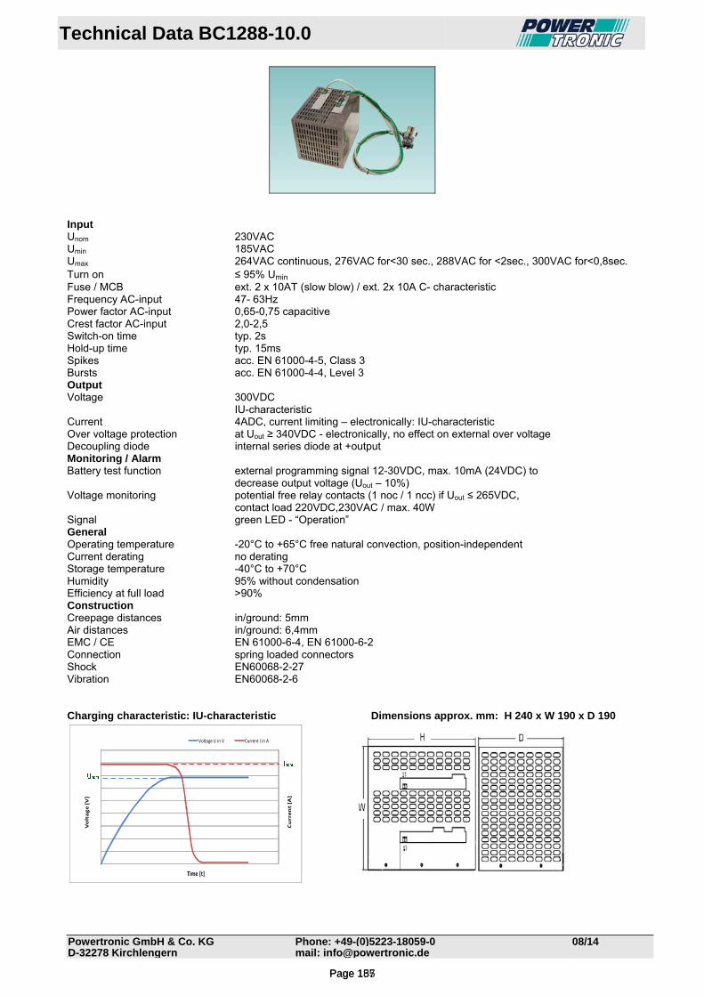
Technical Data BC1288-10.0
Powertronic GmbH & Co. KG Phone: +49-(0)5223-18059-0 08/14D-32278 Kirchlengern mail: [email protected]
Input Unom 230VAC Umin 185VAC Umax 264VAC continuous, 276VAC for<30 sec., 288VAC for <2sec., 300VAC for<0,8sec. Turn on ≤ 95% Umin Fuse / MCB ext. 2 x 10AT (slow blow) / ext. 2x 10A C- characteristic Frequency AC-input 47- 63Hz Power factor AC-input 0,65-0,75 capacitive Crest factor AC-input 2,0-2,5 Switch-on time typ. 2s Hold-up time typ. 15ms Spikes acc. EN 61000-4-5, Class 3 Bursts acc. EN 61000-4-4, Level 3 Output Voltage 300VDC IU-characteristic Current 4ADC, current limiting – electronically: IU-characteristic Over voltage protection at Uout ≥ 340VDC - electronically, no effect on external over voltage Decoupling diode internal series diode at +output Monitoring / Alarm Battery test function external programming signal 12-30VDC, max. 10mA (24VDC) to decrease output voltage (Uout – 10%) Voltage monitoring potential free relay contacts (1 noc / 1 ncc) if Uout ≤ 265VDC, contact load 220VDC,230VAC / max. 40W Signal green LED - “Operation” General Operating temperature -20°C to +65°C free natural convection, position-independent Current derating no derating Storage temperature -40°C to +70°C Humidity 95% without condensation Efficiency at full load >90% Construction Creepage distances in/ground: 5mm Air distances in/ground: 6,4mm EMC / CE EN 61000-6-4, EN 61000-6-2 Connection spring loaded connectors Shock EN60068-2-27 Vibration EN60068-2-6 Charging characteristic: IU-characteristic Dimensions approx. mm: H 240 x W 190 x D 190
Current [A]
Voltage [V]
Time [t]
Voltage U in V Current I in A
Page 157Page 185
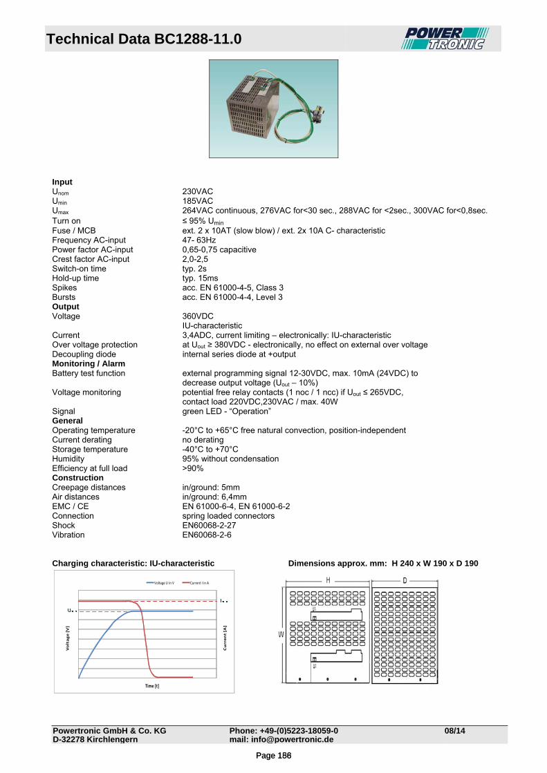
Technical Data BC1288-11.0
Powertronic GmbH & Co. KG Phone: +49-(0)5223-18059-0 08/14D-32278 Kirchlengern mail: [email protected]
Input Unom 230VAC Umin 185VAC Umax 264VAC continuous, 276VAC for<30 sec., 288VAC for <2sec., 300VAC for<0,8sec. Turn on ≤ 95% Umin Fuse / MCB ext. 2 x 10AT (slow blow) / ext. 2x 10A C- characteristic Frequency AC-input 47- 63Hz Power factor AC-input 0,65-0,75 capacitive Crest factor AC-input 2,0-2,5 Switch-on time typ. 2s Hold-up time typ. 15ms Spikes acc. EN 61000-4-5, Class 3 Bursts acc. EN 61000-4-4, Level 3 Output Voltage 360VDC IU-characteristic Current 3,4ADC, current limiting – electronically: IU-characteristic Over voltage protection at Uout ≥ 380VDC - electronically, no effect on external over voltage Decoupling diode internal series diode at +output Monitoring / Alarm Battery test function external programming signal 12-30VDC, max. 10mA (24VDC) to decrease output voltage (Uout – 10%) Voltage monitoring potential free relay contacts (1 noc / 1 ncc) if Uout ≤ 265VDC, contact load 220VDC,230VAC / max. 40W Signal green LED - “Operation” General Operating temperature -20°C to +65°C free natural convection, position-independent Current derating no derating Storage temperature -40°C to +70°C Humidity 95% without condensation Efficiency at full load >90% Construction Creepage distances in/ground: 5mm Air distances in/ground: 6,4mm EMC / CE EN 61000-6-4, EN 61000-6-2 Connection spring loaded connectors Shock EN60068-2-27 Vibration EN60068-2-6 Charging characteristic: IU-characteristic Dimensions approx. mm: H 240 x W 190 x D 190
Current [A]
Voltage [V]
Time [t]
Voltage U in V Current I in A
Page 158Page 186
POWERTRONIC
Industrielle Leistungselektronik
GmbH & Co. KG
Sülkampweg 31
D-32278 Kirchlengern
Telefon: +49 5223 18059-0
Telefax: +49 5223 18059-25
E-Mail: [email protected]
Internet: www.powertronic.de


![STATUS OF DVCS ANALYSIS FROM E1-6 DATA · 2017. 3. 30. · 18000 20000 22000-t [GeV2] 0 0.2 0.4 0.6 0 2000 4000 6000 8000 10000 12000 2 (epX) [GeV2] X M −0.05 0 0.05 0 2000 4000](https://static.fdocument.org/doc/165x107/611df3992340b5255074a0b8/status-of-dvcs-analysis-from-e1-6-data-2017-3-30-18000-20000-22000-t-gev2.jpg)