Basics of Synchrotron Radiation Beamlines and...
46
Basics of Synchrotron Radiation Beamlines and Detectors •Basics of synchrotron radiation •X-ray optics as they apply to EXAFS experiments •Detectors
Transcript of Basics of Synchrotron Radiation Beamlines and...
Basics of Synchrotron Radiation Beamlines and Detectors
•Basics of synchrotron radiation
•X-ray optics as they apply to EXAFS experiments
•Detectors
Important properties of Synchrotron Radiation
• Tunability• High flux• Collimation• Polarization• Time structure
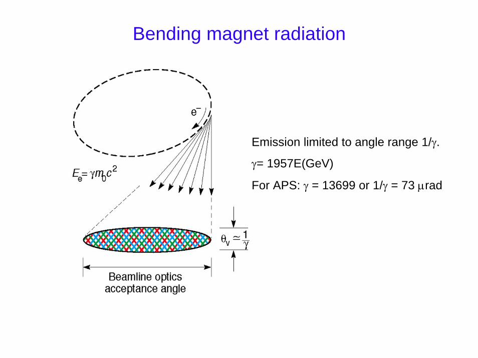
Bending magnet radiation
Emission limited to angle range 1/γ.
γ= 1957E(GeV)
For APS: γ = 13699 or 1/γ = 73 µrad
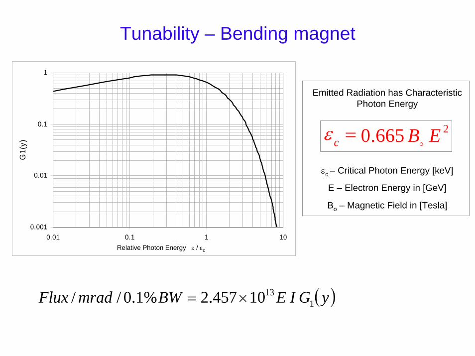
Tunability – Bending magnet
0.001
0.01
0.1
1
0.01 0.1 1 10y
G1(
y)
Emitted Radiation has Characteristic Photon Energy
εc – Critical Photon Energy [keV]
E – Electron Energy in [GeV]
Bo – Magnetic Field in [Tesla]
2665.0 EBc o=ε
Relative Photon Energy ε / εc
( )yGIEBWmradFlux 11310457.2%1.0// ×=
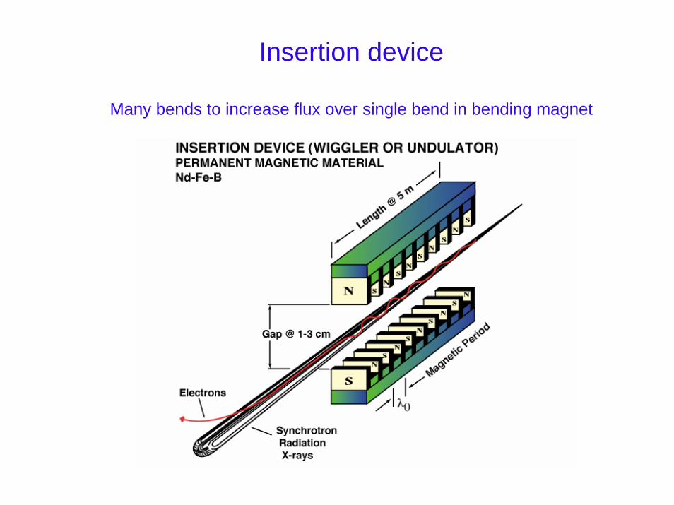
Insertion device
Many bends to increase flux over single bend in bending magnet
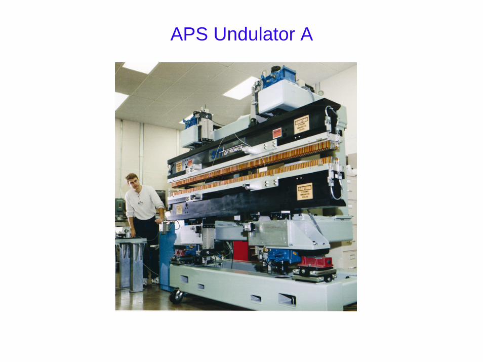
APS Undulator A
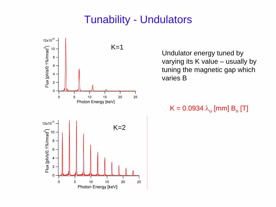
Tunability - Undulators
K=1Undulator energy tuned by varying its K value – usually by tuning the magnetic gap which varies B
K = 0.0934 λu [mm] Bo [T]
K=2
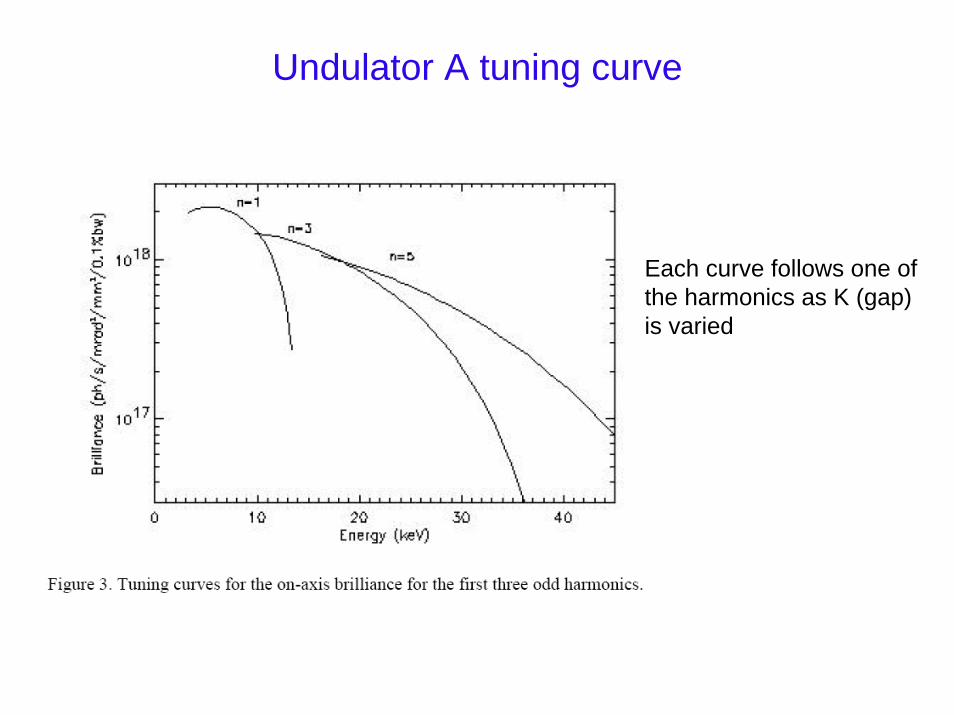
Each curve follows one of the harmonics as K (gap) is varied
Undulator A tuning curve
Source characterization
Flux – photons/sec/bandwidthBandwidth usually chosen as 0.1%Most applications use 0.01-0.02%
Spectral Brilliance - flux/source size/source divergence
Photons/sec/0.1% bandwidth/mm2/mrad2
Liouville’s theorem – brilliance is conservedOptics can’t improve brilliance of source
Higher Brilliance implies more flux on small samples
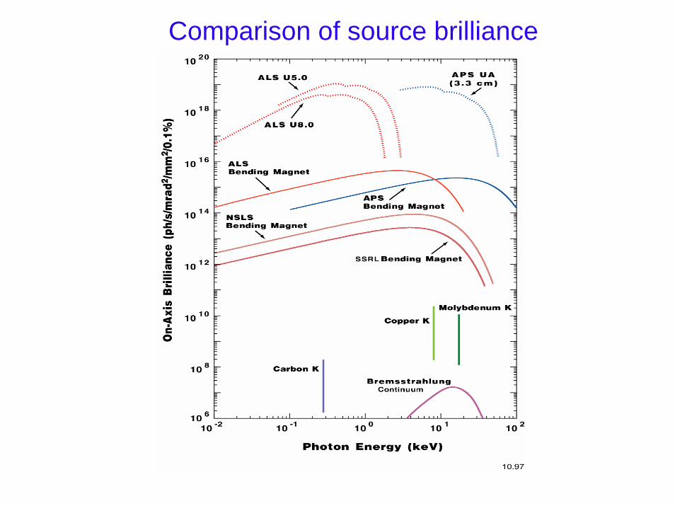
Comparison of source brilliance
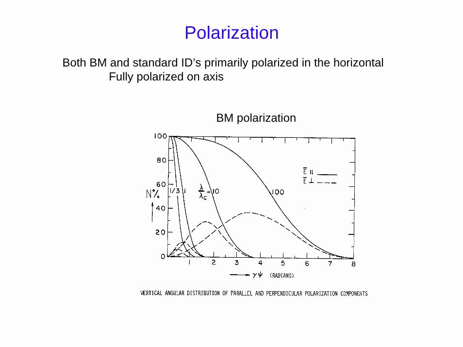
PolarizationBoth BM and standard ID’s primarily polarized in the horizontal
Fully polarized on axis
BM polarization
Time structure
Storage rings store charge in discreet bunches– Short pulses (100psec)
– 272 kHz circulation rate for an individual bunch at APS
– Many patterns possible (24, 324, 1296 bunches, hybrid fill with an isolated bunch)
– Generally not important, but can affect the deadtime of fast detectors
Current gradually decays– Close shutters to refill
– Topoff : refill with shutters open
X-ray Optics
• Mirror Optics
• Perfect crystals
• Typical beamline setups

Mirror optics
Glancing angle optics
– For small enough angles reflectivity nearly 100%
– Achromatic for energies less than critical energy
– Ultra-smooth surfaces needed (0.5 nm roughness)
– Critical energy approximately linearly related to angle
For example, for Rh,
Ec(keV) = 68/angle(mrad)
– Small angles mean mirrors need to be long
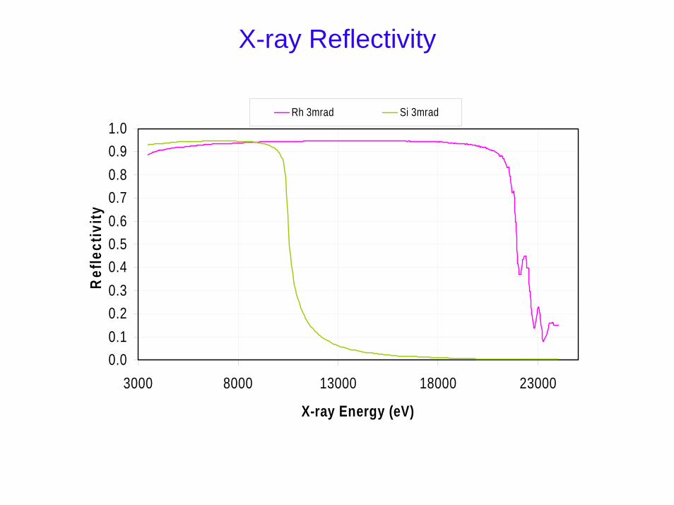
X-ray Reflectivity
0.00.10.20.30.40.50.60.70.80.91.0
3000 8000 13000 18000 23000
X-ray Energy (eV)
Ref
lect
ivity
Rh 3mrad Si 3mrad
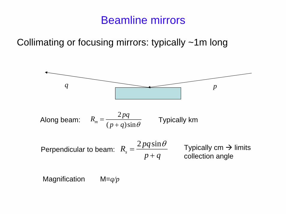
Beamline mirrors
Collimating or focusing mirrors: typically ~1m long
pq
2( )sinm
pqRp q θ
=+
Typically kmAlong beam:
2 sins
pqRp q
θ=
+Typically cm limits collection angle
Perpendicular to beam:
Magnification M=q/p
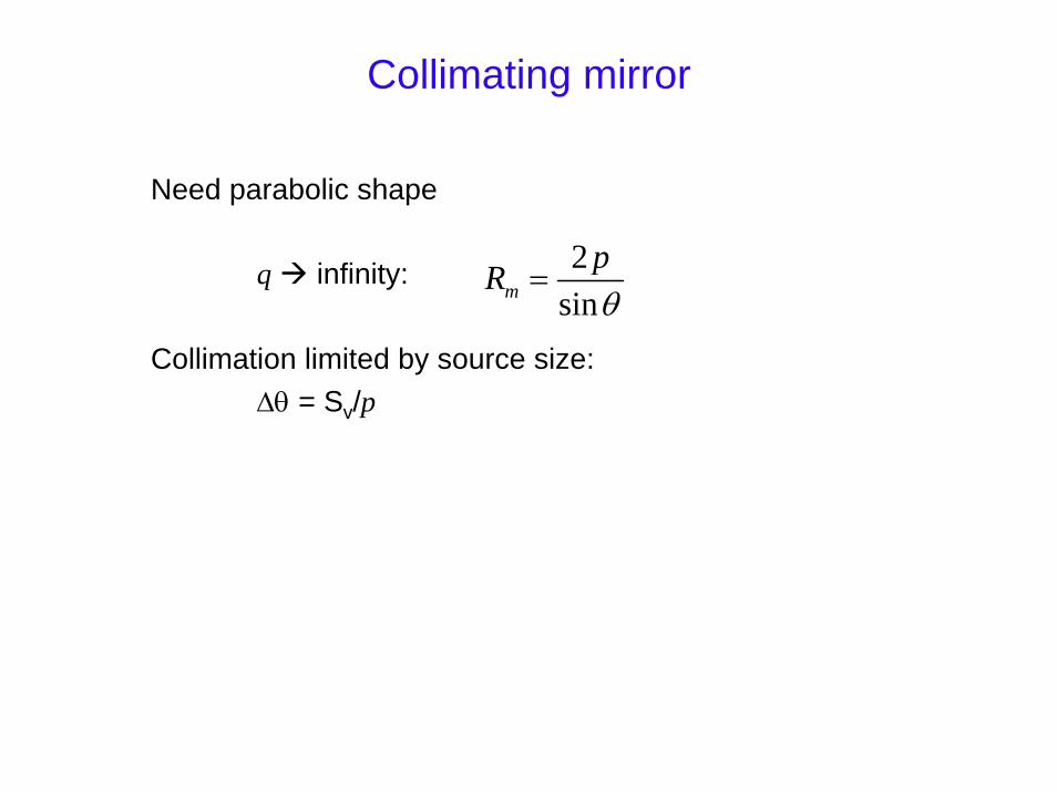
Collimating mirror
Need parabolic shape
q infinity:
Collimation limited by source size:∆θ = Sv/p
2sinm
pRθ
=
ISO 9001CERTIFIED
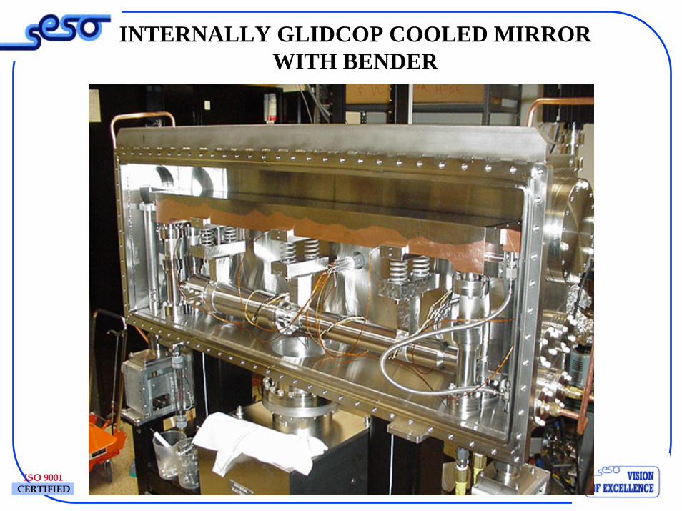
INTERNALLY GLIDCOP COOLED MIRRORWITH BENDER
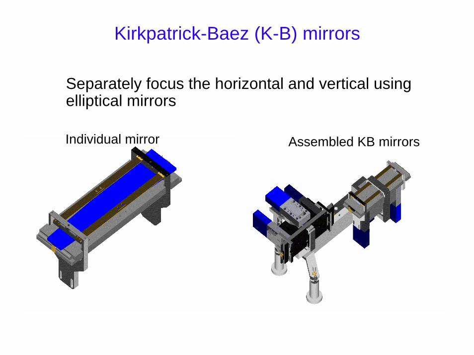
Kirkpatrick-Baez (K-B) mirrors
Separately focus the horizontal and vertical using elliptical mirrors
Individual mirror Assembled KB mirrors
X-ray Optics – perfect crystals
• Bragg reflection and energy resolution
• Monochromators
• Detuning
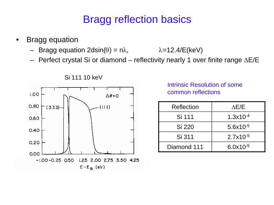
Bragg reflection basics
• Bragg equation– Bragg equation 2dsin(θ) = nλ, λ=12.4/E(keV)– Perfect crystal Si or diamond – reflectivity nearly 1 over finite range ∆E/E
Si 111 10 keVIntrinsic Resolution of some common reflections
Reflection ∆E/ESi 111 1.3x10⁻⁴
Si 220 5.6x10⁻⁵
Si 311 2.7x10⁻⁵
Diamond 111 6.0x10⁻⁵
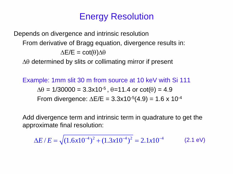
Energy Resolution
Depends on divergence and intrinsic resolutionFrom derivative of Bragg equation, divergence results in:
∆E/E = cot(θ)∆θ∆θ determined by slits or collimating mirror if present
Example: 1mm slit 30 m from source at 10 keV with Si 111∆θ = 1/30000 = 3.3x10⁻⁵ , θ=11.4 or cot(θ) = 4.9From divergence: ∆E/E = 3.3x10⁻⁵(4.9) = 1.6 x 10⁻⁴
Add divergence term and intrinsic term in quadrature to get the approximate final resolution:
4 2 4 2 4/ (1.6 10 ) (1.3 10 ) 2.1 10E E x x x− − −∆ = + = (2.1 eV)
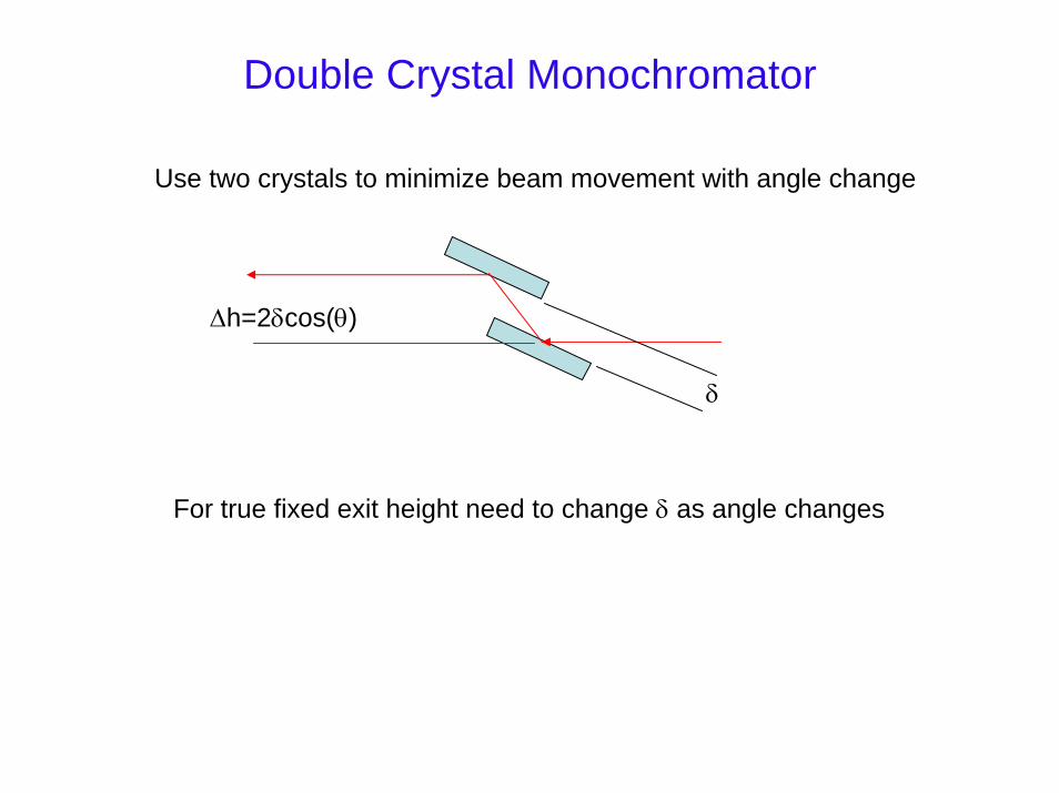
Double Crystal Monochromator
Use two crystals to minimize beam movement with angle change
∆h=2δcos(θ)
δ
For true fixed exit height need to change δ as angle changes
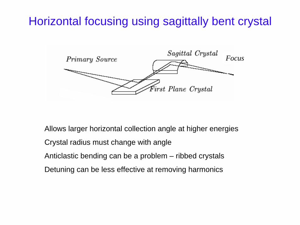
Horizontal focusing using sagittally bent crystal
Focus
Allows larger horizontal collection angle at higher energies
Crystal radius must change with angle
Anticlastic bending can be a problem – ribbed crystals
Detuning can be less effective at removing harmonics
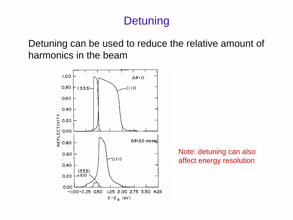
Detuning
Detuning can be used to reduce the relative amount of harmonics in the beam
Note: detuning can also affect energy resolution
Some typical beamline layouts
• Monochromator only
• Monochromator with focusing mirror
• Collimating mirror – monochromator – focusing mirror
• Collimating mirror – sagittal focusing mono – focusing
mirror
Detectors
• Signal to noise requirements• Possible performance of ideal detectors• Short description of some common detectors
– Ion chambers– Multielement and deadtime issues– Filters and slits– Diffraction based detectors
S/N requirements
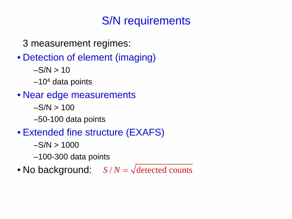
3 measurement regimes:• Detection of element (imaging)
–S/N > 10–104 data points
• Near edge measurements–S/N > 100–50-100 data points
• Extended fine structure (EXAFS)–S/N > 1000–100-300 data points
• No background: / detected countsS N =
Performance of Ideal Fluorescence Detector
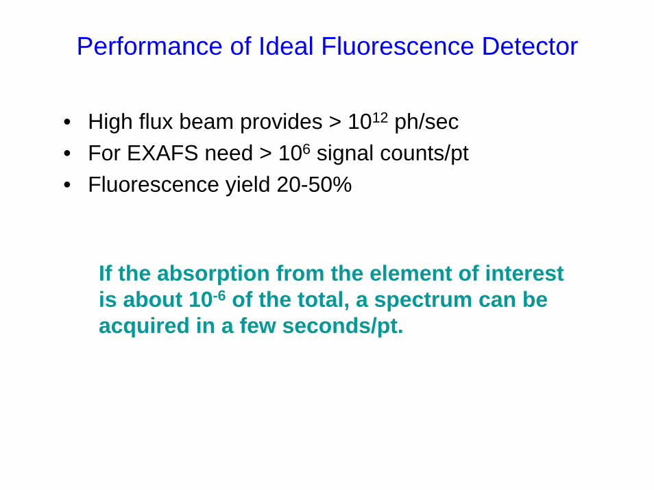
• High flux beam provides > 1012 ph/sec• For EXAFS need > 106 signal counts/pt• Fluorescence yield 20-50%
If the absorption from the element of interest is about 10-6 of the total, a spectrum can be acquired in a few seconds/pt.
Practical limitations
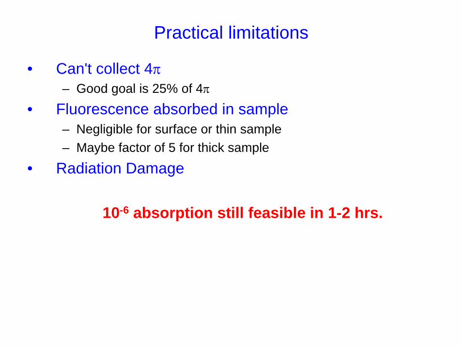
• Can't collect 4π– Good goal is 25% of 4π
• Fluorescence absorbed in sample– Negligible for surface or thin sample– Maybe factor of 5 for thick sample
• Radiation Damage
10-6 absorption still feasible in 1-2 hrs.
Example for Fe
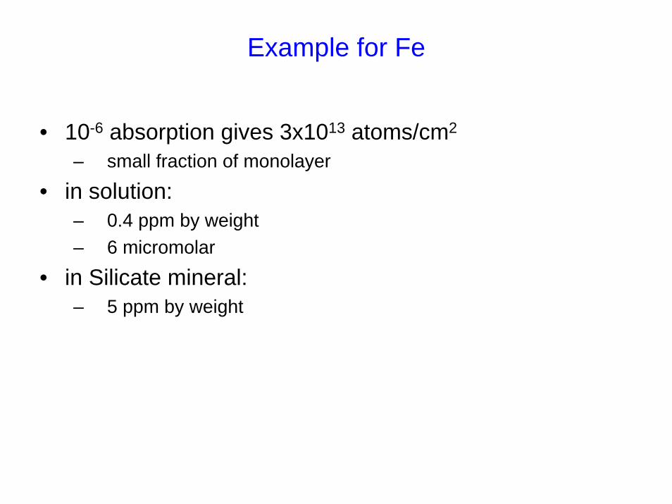
• 10-6 absorption gives 3x10¹³ atoms/cm2
– small fraction of monolayer
• in solution:– 0.4 ppm by weight– 6 micromolar
• in Silicate mineral:– 5 ppm by weight
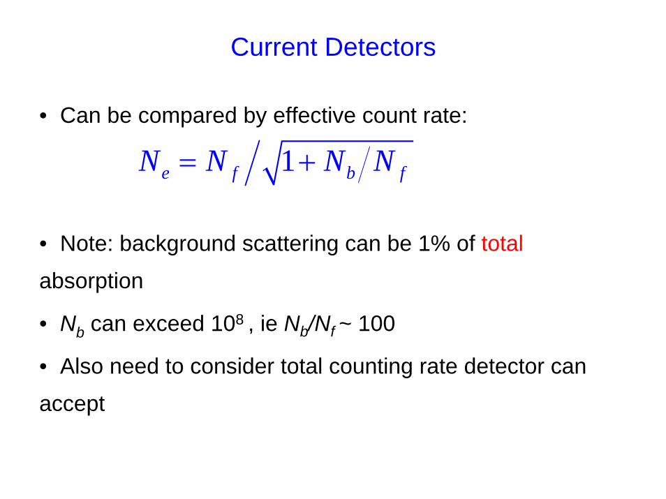
Current Detectors
• Can be compared by effective count rate:
• Note: background scattering can be 1% of total
absorption
• Nb can exceed 108 , ie Nb/Nf ~ 100
• Also need to consider total counting rate detector can
accept
1e f b fN N N N= +
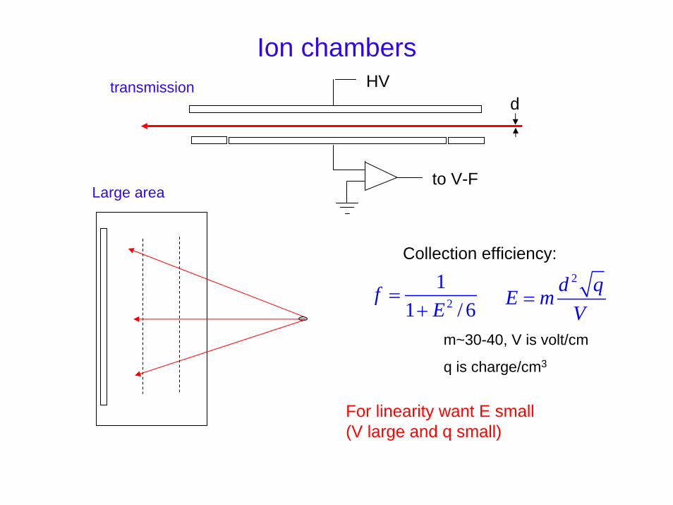
Ion chambersHVtransmission
d
to V-FLarge area
Collection efficiency:
2
11 / 6
fE
=+
2d qE mV
=
m~30-40, V is volt/cm
q is charge/cm3
For linearity want E small(V large and q small)
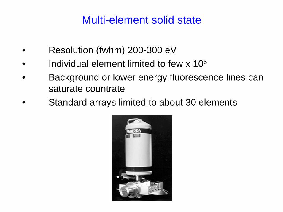
Multi-element solid state
• Resolution (fwhm) 200-300 eV• Individual element limited to few x 105
• Background or lower energy fluorescence lines can saturate countrate
• Standard arrays limited to about 30 elements
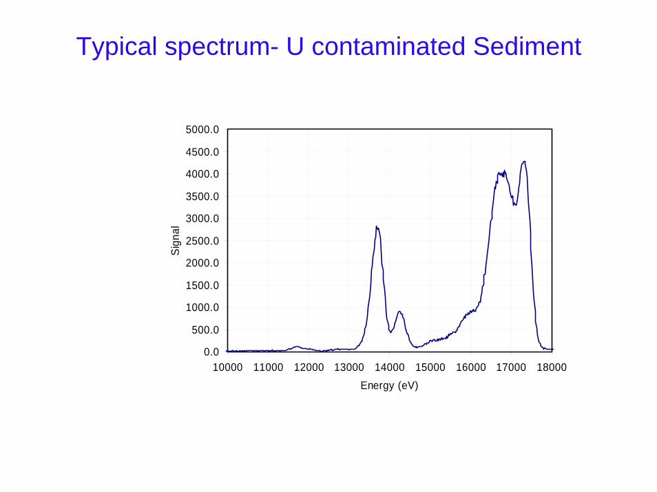
Typical spectrum- U contaminated Sediment
0.0
500.0
1000.0
1500.0
2000.0
2500.0
3000.0
3500.0
4000.0
4500.0
5000.0
10000 11000 12000 13000 14000 15000 16000 17000 18000Energy (eV)
Sign
al
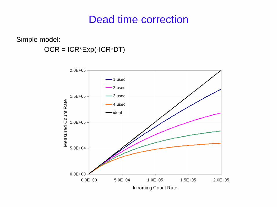
Dead time correction
Simple model:OCR = ICR*Exp(-ICR*DT)
0.0E+00
5.0E+04
1.0E+05
1.5E+05
2.0E+05
0.0E+00 5.0E+04 1.0E+05 1.5E+05 2.0E+05
Incoming Count Rate
Mea
sure
d C
ount
Rat
e
1 usec
2 usec
3 usec
4 usec
ideal
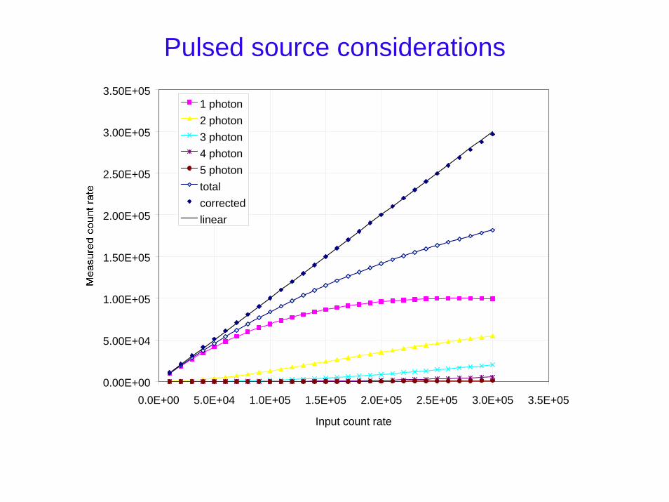
Pulsed source considerations
0.00E+00
5.00E+04
1.00E+05
1.50E+05
2.00E+05
2.50E+05
3.00E+05
3.50E+05
0.0E+00 5.0E+04 1.0E+05 1.5E+05 2.0E+05 2.5E+05 3.0E+05 3.5E+05
Input count rate
1 photon2 photon3 photon4 photon5 photontotalcorrectedlinear
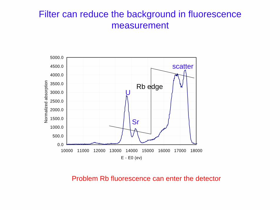
Filter can reduce the background in fluorescence measurement
0.0
500.0
1000.0
1500.0
2000.0
2500.0
3000.0
3500.0
4000.0
4500.0
5000.0
10000 11000 12000 13000 14000 15000 16000 17000 18000Energy (eV)
Sign
al
0.0
500.0
1000.0
1500.0
2000.0
2500.0
3000.0
3500.0
4000.0
4500.0
5000.0
10000 11000 12000 13000 14000 15000 16000 17000 18000E - E0 (ev)
Nor
mal
ized
abs
orpt
ion
U
Sr
scatter
Rb edge
Problem Rb fluorescence can enter the detector
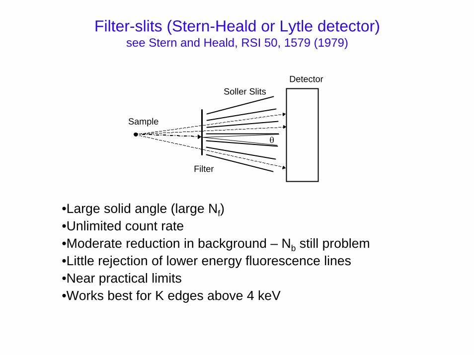
Filter-slits (Stern-Heald or Lytle detector)see Stern and Heald, RSI 50, 1579 (1979)
θ
DetectorSoller Slits
Filter
Sample
•Large solid angle (large Nf)•Unlimited count rate•Moderate reduction in background – Nb still problem•Little rejection of lower energy fluorescence lines•Near practical limits•Works best for K edges above 4 keV
Diffraction based detectors
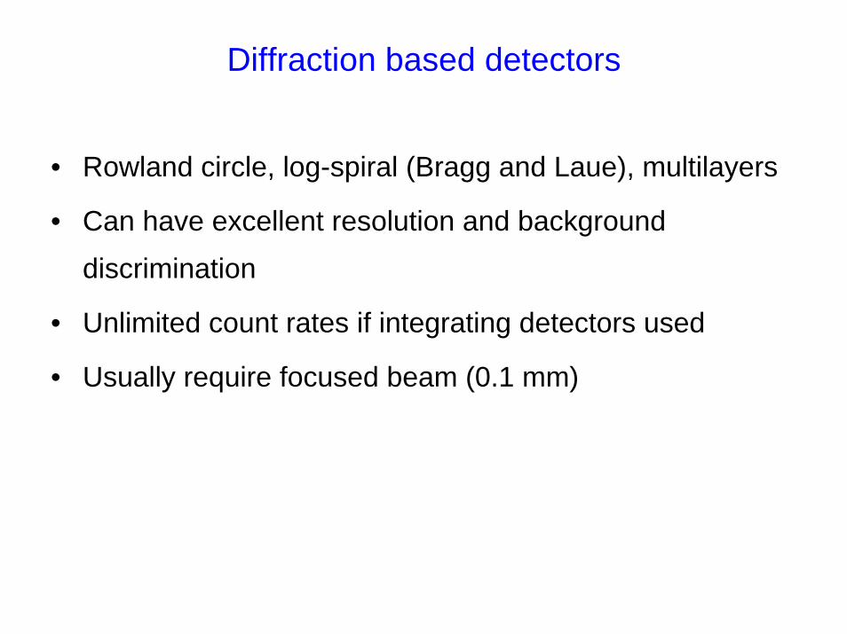
• Rowland circle, log-spiral (Bragg and Laue), multilayers
• Can have excellent resolution and background
discrimination
• Unlimited count rates if integrating detectors used
• Usually require focused beam (0.1 mm)
WDX detector (Rowland circle)
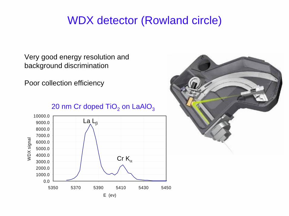
Very good energy resolution and background discrimination
Poor collection efficiency
0.01000.02000.03000.04000.05000.06000.07000.08000.09000.0
10000.0
5350 5370 5390 5410 5430 5450
E (ev)
WD
X si
gnal
La Lβ
Cr Kα
20 nm Cr doped TiO2 on LaAlO3
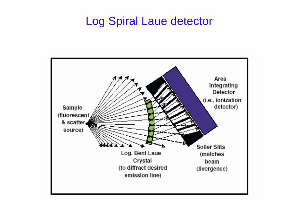
Log Spiral Laue detector
Log spiral detector (cont.)
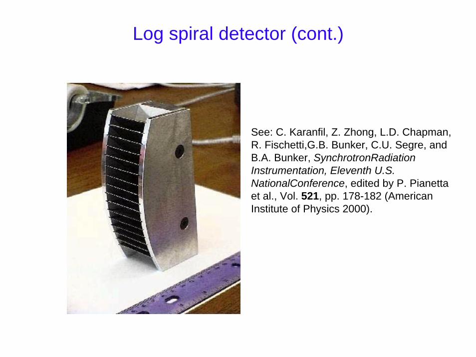
See: C. Karanfil, Z. Zhong, L.D. Chapman, R. Fischetti,G.B. Bunker, C.U. Segre, and B.A. Bunker, SynchrotronRadiationInstrumentation, Eleventh U.S. NationalConference, edited by P. Pianettaet al., Vol. 521, pp. 178-182 (American Institute of Physics 2000).
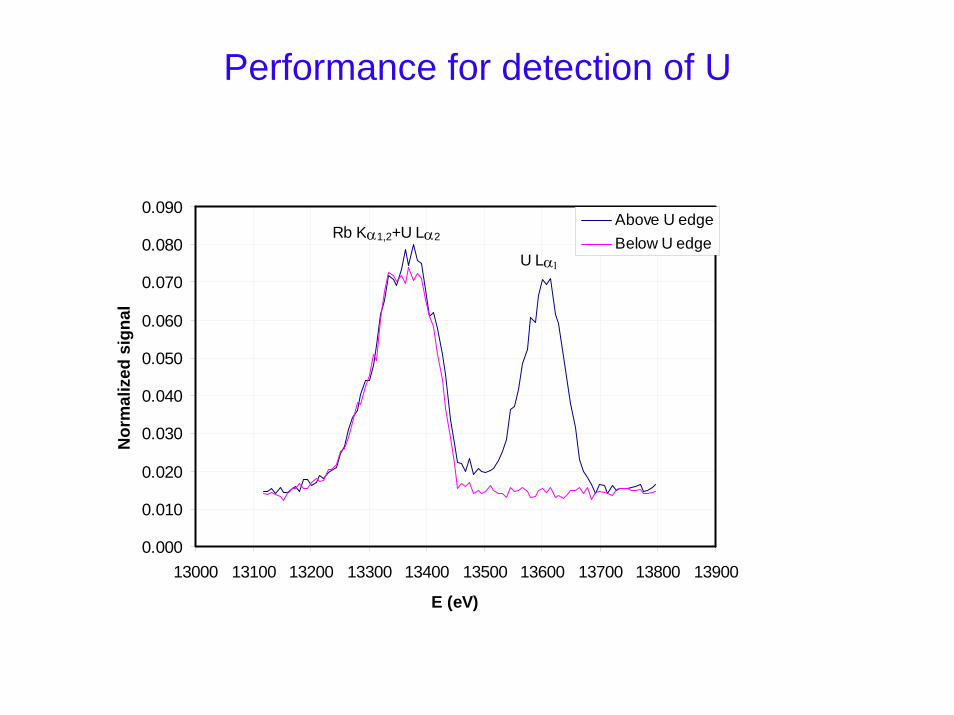
Performance for detection of U
0.000
0.010
0.020
0.030
0.040
0.050
0.060
0.070
0.080
0.090
13000 13100 13200 13300 13400 13500 13600 13700 13800 13900
E (eV)
Nor
mal
ized
sig
nal
Above U edgeBelow U edge
Rb Kα1,2+U Lα2
U Lα1
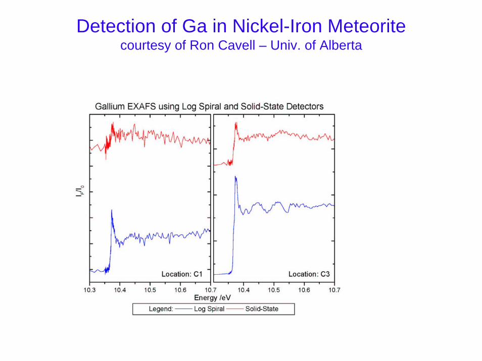
Detection of Ga in Nickel-Iron Meteoritecourtesy of Ron Cavell – Univ. of Alberta
Further development of both solid-state arrays and diffraction-based detectors warranted
• Solid state arrays:– Need to handle >108 hz– Preferable to keep resolution close to 200 eV– Si drift detectors look promising
• Diffraction based detectors:– Need to increase efficiency (multiple crystals)– Should strive for better resolution than solid state detectors– If above met, best bet for extreme diluteness– Need 0.1-0.2 mm high beam